diamond like carbon nanocomposites for optical and...
TRANSCRIPT

HORIZON 2020 EUROPEAN UNION FUNDING FOR RESEARCH & INNOVATION
Diamond like carbon nanocomposites for optical and electrical applications
S.Tamulevičius
Institute of Materials Science Kaunas University of Technology
K. Baršausko St. 59Kaunas LT-51423
Lithuania www.fei.ktu.lt
[email protected] +37037314423; Ph.:+37037327601

Acknowledgments:
Dr. Šarūnas Meškinis, Dr. Asta Tamulevičienė, Dr. Iryna Yaremchuk, Dr. Rimantas GudaitisDr. TomasTamulevičius,PhD student Tadas Juknius,PhD student Dainius VirganavičiusPhD student Arvydas Čiegis

Outline
• Introduction
�Nanoscience and nanotechnology
�What is Diamond Like Carbon (DLC) and how to produce it?
� Applications of DLC
�DLC based nanocomposites
• DLC as a functional material
�Deposition of a-C, a-C:H, a-C:SiOx, a-C:Ag films
�Optical sensors based on DLC and DLC nanocomposites
�Plasmonic properties of DLC silver nanocomposites
�Structuring of DLC nanocomposites

K. Baršausko St. 59, Kaunas, Lithuania
• Institute of Materials Science is a part of National Open Access R&D Centrewithin Kaunas University of Technology
KTU campus
Where to find us
Opened November 11, 2014

www.holtida.lt
Anti counterfeiting applicationsSpin-off
Available facilities

Technet_nano, Baltic state region programme
An alliance of public clean rooms and research facilities for companies in the Baltic Sea Region
• Technet_nano combines well-established competencies and R&D facilities for the benefit of their customers.
• We provide high-quality services, fostering innovation and new product development.
12 Partners from 7 countries
www.technet-nano.eu
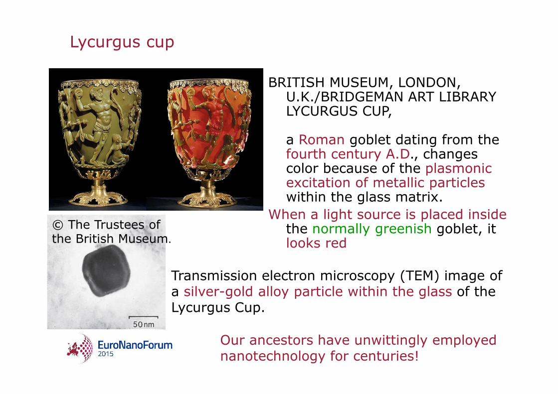
Lycurgus cup
BRITISH MUSEUM, LONDON, U.K./BRIDGEMAN ART LIBRARY LYCURGUS CUP,
a Roman goblet dating from the fourth century A.D., changes color because of the plasmonicexcitation of metallic particles within the glass matrix.
When a light source is placed inside the normally greenish goblet, it looks red
Transmission electron microscopy (TEM) image of a silver-gold alloy particle within the glass of the Lycurgus Cup.
Our ancestors have unwittingly employednanotechnology for centuries!
© The Trustees of the British Museum.

Dichroic glass
• The dichroic glass consists of a translucent glass containing colloidal gold and silver particles dispersed in the glass matrix in certain proportions
• Glass has the property of displaying a particular transmitted color and a completely different reflected color, as certain wavelengths of light either pass through or are reflected
http://www.flickr.com/photos/zygzee/324322772/
Dichroic glass pendant
Cranberry glass or 'Gold Ruby‘
http://en.wikipedia.org/wiki/File:Goldrubinglas_Schatzkammer_München.jpg
The finished, hardened glass is a type of colloid, a solid phase (gold) dispersed inside another solid phase (glass).
• Some historians believe a form of this glass was first made in the late Roman Empire.

Sustainable technologies for the next decade
http://www.scientifica.com
Sustainable investment strategies for the 21-st century• Doing More With Less (use of nanomaterials)
Stronger and lighter materials based on nanotechnologyFuel cells of high energy efficiency and performance
• Replacing scarce resourcesDeveloping of new processes that do not use rare resources (rear earths, indium etc.)Processes using carbon nanotubes, metallic nanoparticles
http://www.nims.go.jp/eng/index.html
• “Materials research for creating tomorrow”
• From fundamental research/foundational R&D on materials to research required by society
Sustainable technologies for the next decade

Nanocomposites
• A nanocomposite is a multiphase solid material where one of the phases has one, two or three dimensions of less than 100 nm, or structures having nano-scale repeat distances between the different phases that make up the material.
• The mechanical, electrical, thermal, optical, electrochemical, catalytic properties of the nanocompositediffer markedly from that of the component materials.
� Ceramic-matrix nanocomposites (oxides, nitrides, borides, silicides etc. encompassing a metal as the second component)
� Metal-matrix nanocomposites (carbon nanotube, boronnitride and carbon nitride metal matrix composites etc.)
� Polymer-matrix nanocomposites
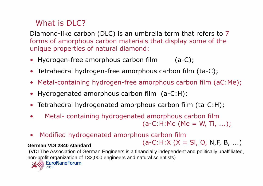
What is DLC?Diamond-like carbon (DLC) is an umbrella term that refers to 7 forms of amorphous carbon materials that display some of the unique properties of natural diamond:
• Hydrogen-free amorphous carbon film (a-C);
• Tetrahedral hydrogen-free amorphous carbon film (ta-C);
• Metal-containing hydrogen-free amorphous carbon film (aC:Me);
• Hydrogenated amorphous carbon film (a-C:H);
• Tetrahedral hydrogenated amorphous carbon film (ta-C:H);
• Metal- containing hydrogenated amorphous carbon film (a-C:H:Me (Me = W, Ti, ...);
• Modified hydrogenated amorphous carbon film (a-C:H:X (X = Si, O, N,F, B, ...)German VDI 2840 standard
(VDI The Association of German Engineers is a financially independent and politically unaffiliated, non-profit organization of 132,000 engineers and natural scientists)

What is DLC?
• Diamond is one of the best known allotropes of carbon - C atoms in diamond are arranged in a cubic lattice (cubic orientation of sp3
bonding)
• DLC coatings are a mixture of sp2 and sp3 bonded carbonatoms with a hydrogen concentration between 0 - 80%.
• C atoms in graphite are bonded in flat hexagonal lattices, which are then layered in sheets.

What is DLC?
Classification of non-crystalline carbons
• ta-C (doesn’t contain H), concentration of sp3 greater than 60%
• Hydrogenated amorphous carbons (a-C:H):
� PLCH – polymer-like a-C:H (concentration of H 40-70 at %);
�DLCH – diamond like a-C:H (H 20-40%)
� ta-C:H – hydrogenated tetrahedral amorphous carbon (sp3-70%, H-25-30%)
� GLCH – graphite-like a-C:H(glassy) (C-H<20at%, sp3 content <20%)
• Amorphous carbons (a-C).Cinzia Casiraghi, John Robertson, and Andrea C. Ferrari,Jan-Febr. 2007, vol. 10, No 1-2, Materials Today, p. 44

Why DLC?
• Low Deposition Temperature (R.T. – 200oC) No limitation of
Materials, the various forms of DLC can be applied to almost any material that is compatible with a vacuum environment• Smooth Surface (Roughness : few nm)
• Uniform Large Area Deposition (High Productivity and Low Cost)
• Wide Range of Physical Properties (Tunability of the Properties) :
� High hardness (10-80 GPa) � Low friction and high wear resist (coefficient of friction against all
other materials lower than Teflon, non-sticking characteristics)� Chemical Inertness� Optical Transmittance - transparence for visible and infrared
light (60-90 %)� high electrical resistivity (they can be tailored to have a wide
range of electrical resistivity)� thermal conductivity (4-18 W×cm-1×K-1)� radiation resistance
Matured Technology with Global Competency

DLC - applications
http://depts.washington.edu
J.Robertson, Diamond-like amorphous carbon, Materials Science and Engineering, R37, 2002, p.129-281,
• Magnetic storage - carbon coatings for magnetic disks
� The magnetic disk, head and its slider are each coated with a thin, smooth protective layer of diamond-like carbon (DLC).
• Mechanical applications� DLC Coated Sliding Tools� DLC Coated Forming Dies, CD DVD moulds,
DLC Coated Chip Carrying Tools, razor etc.
• Biomedical applications- Biological Compatibility, Chemical Compatibility, Mechanical Compatibility
� DLC coated stents, heart valves, blood pumpsare now available on the market.
� DLC Coating on Femoral Ball and DLC Coated Artificial Joints
• Optical applications� Protection offered to fragile ZnS infrared (IR)
windows by coatings of the pure DLC (ta-C)
DIAMOND AS® Stent
Cinzia Casiraghi, John Robertson, and Andrea C. Ferrari, Diamond-like carbon for data and beer storage, Jan-Febr. 2007, vol. 10, No 1-2, Materials Today, p. 44

What is DLC?Metal-doped Dylyn (Me/a-C:H/a-Si:O; DLN)
The electrical characteristics of the coatings can be tailored by the addition of metal dopants. This creates an engineered surface for specialized applications requiring a combination of wear, low friction and electrical conductivity. Typical applications include those requiring static discharge in addition to wear resistance,
such as watermanufacturing.
The mechanical properties of the hard carbon films can be improved by incorporating a small percentage of metal dopant(usually ~5% titanium) in the final carbon structure.The resulting films have excellent friction and wear properties:
• microhardness of up to 4000Hv• coefficient of friction during dry running in air against cemented WC always <0.15• a wear rate 20% that of titanium nitride• exceedingly low counterface wear.
http://www.bekaert.com/bac/Products/ http://www.azom.com/details.asp?ArticleID=623#_Applications

Deposition method:
DC hydrocarbon ion beam depositionby hollow cathode electrostatic ion source
Hydrocarbons used in the synthesis:
• Acetylene gas (C2H2) ( for undoped diamond like carbon films)
• Hexametyldisiloxane ((CH3)3SiOSi(CH3)3) vapor and hydrogen gasmixture (Silicon oxide doped diamond like carbon film)
• Hexametyldisiloxane ((CH3)3SiOSi(CH3)3) vapor and acetylene gas
• Hexametyldisiloxane ((CH3)3SiOSi(CH3)3) vapor and nitrogen gasmixture(Silicon oxide and nitrogen doped DLC)
V. Kopustinskas, Š. Meškinis, S. Tamulevičius, M. Andrulevičius, B. Čižiūte. and G. Niaura Synthesis of the silicon and silicon oxide doped a-
C:H films from hexamethyldisiloxane vapor by DC ion beamSurface and Coatings Technology, Vol. 200, Iss. 22-23, 2006, p.6240-6244
DLC deposition technology and materials

Technological conditions of deposition
Residual gas pressure (2⋅10-4) Pa
Total gas pressure (2⋅10-2) Pa
Ion beam energy (0.3÷1) keV
Ion current density 0.01 –0.1 mA/cm2
Deposition temperature 293 K
Substrate: crystalline Si, quartz, Ni, etc.
Thickness of the films 200 nm up to 1µm (for mould production)
Deposition rate (6-7) nm/min

Computer controlled DLC deposition system
1- Gas valve2- Cathode of ion source3- Solenoid4- Anode of ion source5- Sample holder
6- Samples7- Grid8- Data acquisition system9- PC Reagents
• C2H2• C2H2 + N2• (CH3)3SiOSi(CH3)3• (CH3)3SiOSi(CH3)3 + H 2• (CH3)3SiOSi(CH3)3 + C2H2
DLC deposition by direct ion beam

Chemical composition of a-C:H:SiOx films
FFiillmm ((ggaasseess uusseedd ffoorr ssyynntthheessiiss))
AAttoommiicc ccoonncceennttrraattiioonn %%
CCoommppoossiittiioonn rreellaatteedd ttoo SSii
SSii OO CC HHMMDDSS++HH22 1188..6633 2266..8877 5544..55 SSiiOO11..4444CC22..9922 HHMMDDSS++HH22 ((aaff tteerr AArr iioonn bbeeaamm cclleeaanniinngg))
2211..7766
2266..0055
5522..1199
SSiiOO11..22CC22..44
HHMMDDSS++CC22HH22 22..0066 99..5522 8888..4422 SSiiOO44..6622CC4422..9922
In the case of C2H2 the total amount of carbon is contributed by two components (both acetylene and hexamethyldisiloxane).
As a result atomic concentration of the carbon as well as C:O and C: Si ratios are increased.

Optical absorption spectra of DLC films
Š.Meškinis, V. Kopustinskas, K.Šlapikas, S.Tamulevičius, A.Guobienė, R.Gudaitis, V. Grigaliūnas, Thin Solid Films. 2006, Vol. 515, no. 2, p. 636-639.
• Optical and UV transmittance of undoped DLC films depends upon ion beam energy – the higher energy - the lower transmittance.
• Additional doping of the HMDS vapor by N2or Ar gas during the ion beam synthesis process results in increased optical transmittance in UV range.

Optical properties of DLC and SiOx doped DLC
Gas (gas mixture) used for synthesis
Ion energy
(eV)
Refractiveindex(λλλλ=632.8nm)
E04energy
(eV)
C2H2 - 400 2.3 1.58
C2H2 - 300 2.3 2.35
C2H2 - 240 2.3 4.28
(CH3)3SiOSi(CH3)3+H2 - 800 1.8 3.12
(CH3)3SiOSi(CH3)3+H2 10% Ar 800 1.8 3.21
(CH3)3SiOSi(CH3)3+H2 2.5% N2 800 1.8 3.53
(CH3)3SiOSi(CH3)3+H2 10% N2 800 1.8 3.58
(CH3)3SiOSi(CH3)3+H2 20% N2 800 1.7 3.51

DLC - applications
• Microstructures from DLC:SiOx(1200 nm DLC:SiOx on crystalline silicon)
� Bulk micromachining
� SiO2 used as a sacrificial layer
� combination of the lift-off technique and wet chemical etching.
Š. Meškinis, S. Tamulevičius, et al. Micromachining of diamond-like carbon deposited by closed drift ion source forcantileversandmembranes,Materials Science . Vol.15, no3, 2009. p.201-206

DLC mould –thick layer
DLC - applications
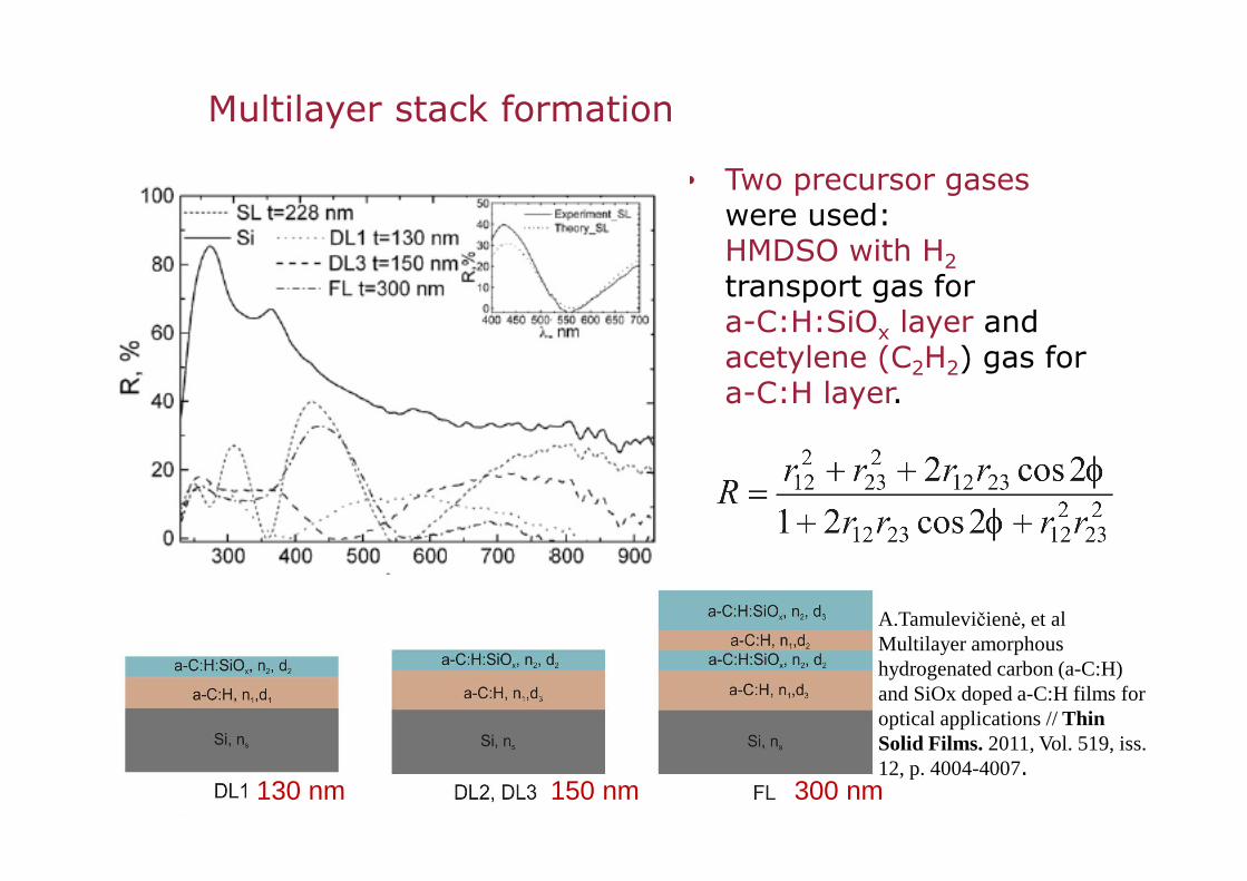
Multilayer stack formation
• Two precursor gaseswere used: HMDSO with H2transport gas for a-C:H:SiOx layer and acetylene (C2H2) gas for a-C:H layer.
130 nm 150 nm 300 nm
A.Tamulevičienė, et al Multilayer amorphous hydrogenated carbon (a-C:H) and SiOx doped a-C:H films for optical applications // Thin Solid Films. 2011, Vol. 519, iss. 12, p. 4004-4007.

Piezoresistive properties
2h b 2
l)-(L F 3=σ
EL
Lσ
∆ε ==
( )( )LL
RR
//
GF∆∆
=
Black color refers to Al, gray color—DLC; distance between the electrodes is 100 mkm
Š. Meškinis, R. Gudaitis, V. Kopustinskas, S. Tamulevičius, Electrical and piezoresistive properties of ion beam deposited DLC films, Applied Surface Science, Volume 254, Issue 16, 15 June 2008, Pages 5252-5256

Smart spacer

Origination using Laser beam Interference Lithography (LIL)
Limiting resolution:λ/2 < d < 13µm (~20)
He-Cd, λ=411.6nm
DLC – applications
( ) ϕθθλ
cossinsin 21 +=d
Tamulevičius T., Tamulevičius S, Andrulevičius M., Griškonis E., Puodžiukynas L., Janušas G., Guobienė A. Formationof periodicmicrostructuresusinginterferencelithography// Experimental Techniques. 2008 Vol. 32, no. 4, p. 23-28.
d=435 nm
Subwavelength gratings

[4]
[2]
No scattering or absorptionSome scattering or absorptionLots of scattering or absorption
Total internal reflection based grating sensor for the determination of refractive index of liquids
4. Mazen l. Hamad et all Applied Spectroscopy, 59, 2005, 16-25

DLC grating for optical biosensors
T. Tamulevičius, R. Šeperys, M. Andrulevičius, V. Kopustinskas, Š. Meškinis, S. Tamulevičius, V. Mikalayeva, R. Daugelavičius, // AppliedSurface Science, 2012, Vol. 258, iss. 23, p. 9292-9296

2008 2011
Optical measurement setup
BS
L4
T.Tamulevičius, R. Šeperys, M.Andrulevičius, S. Tamulevičius,Total internal reflection based sub-wavelength grating sensorfor the determination of refractive index of liquids // Photonics and Nanostructures - Fundamentals and Applications..
2011, Vol. 9, iss. 2, p. 140-148.

Practical applications for sensing
T. Tamulevičius, I. Gražulevičiūtė et. al. Advanced Sensors for Safety and Security, NATO Science for Peace and SecuritySeries B: Physics and Biophysics, Springe17 (2013) 199
R=f(λ) RCWA R=f(λ) Experimental
λ=f(c)

T=20 ºC saline solution 0.9 % (SS)• S. aureus in saline solution (“Control”);• Saline solution with addition of 4 x 0.1 ml of Penicilin G (“SS+BP”); • 4 x 0.1 ml addition of PenicilinG/benzylpenicillin (“BP”) into S. aureussaline solution;• 2 x 0.2 ml addition of Penicilin G into S. aureus saline solution;• 1 x 0.4 ml addition of Penicilin G into S. aureus saline solution.
In-situ measurements
0.4 ml BP
Control sample
Tamulevičius S. et all . In-situ measurements of bacteria resistance to antimicrobial agents employing leakymode sub-wavelength diffraction grating// Sensors and actuators B: Chemical. 2014, Vol. 204, p. 799-806.

Deposition of a-C:H:Ag films
• Hydrogenated silver containing DLC films were deposited by DC unbalanced magnetron sputtering of silver target.� Substrate bias 0 - -200V� U 500-700 V, I 0.1-0.2 A
• Mixture of the hydrocarbons (acetylene) and argon was used in the reactive sputtering. � Flux: Ar 70-80 sccm, C2H2 20 sccm
• Polished polycrystalline alumina, monocrystalline silicon and quartz substrates were used.� Thickness of the films in 50-300 nm range� Deposition time 3-8 min
Tamulevičius S. et al Piezoresistive properties of amorphous carbon based nanocomposite thin films deposited by plasmaassistedmethods// Thin Solid Films 2013, Vol. 538, p. 78-84

Deposition of a-C:H:Ag films
C2H2
Ag
Ag
Ag
http://www.kobelco.co.jpZoe H. Barber, J. Mater. Chem., 2006,16, 334-344Costas A. Charitidis, Lubricants 2013, 1 (2), 22-47

Deposition of a-C:H:Ag films
Sample name C2H2 flux (sccm) Ar flux (sccm) Substrate bias (V)LC0 7.8 80 0LC50 7.8 80 −50LC100 7.8 80 −100LC150 7.8 80 −150LC200 7.8 80 −200HC0 11.7 70 0HC50 11.7 70 −50HC100 11.7 70 −100HC150 11.7 70 −150HC200 11.7 70 −200
Deposition conditions, samples’ notation.
Š.Meškinis, A. Čiegis, A.Vasiliauskas, A.Tamulevičienė, K.Šlapikas, R.Juškėnas, G. Niaura, S. Tamulevičius// Applied surface science. 2014, Vol. 317, p. 1041-1046

Deposition of a-C:H:Ag films
0
10
20
30
40
50a
0 5 10 15 20 25 30 35 400
20
40
60
80 b
Num
ber
of n
anoc
lust
ers
Size (nm)
Nanoparticle size distribution for DLC:Ag films 22 at.% of Ag (a)
8 at.% of Ag (b). The histograms were calculated by using AFMimages.
TEM image (overall view”) high resolution TEM image EDS profiling across the line
I. Yaremchuk, et all Nanoscale research letters. 2015, vol. 10, iss. 1, Article no. 157, p. 1-7.

Deposition of a-C:H:Ag films
• Ratio of intensities of the surface plasmon resonancepeak and a-C:H matrix related peak at ∼215–225 nm
increased with Ag atomic concentration for the films containing higher amounts of silver (>5 at.%).
• The shift of plasmonicpeak position to the higher wavelength with the average Ag crystallite size

Deposition of a-C:H:Ag films
Samplename
λplasmonicpeak(nm) Disp(G)
Ag at. conc. (%)
O at. conc. (%)
C at. conc. (%)
LC0 Yes 0.100 22.0 11.3 66.7LC50 Yes 0.226 8.2 10.7 81.2LC100 Yes 0.196 15.2 7.4 77.5LC150 Yes 0.251 4.5 7.7 87.8LC200 Yes 0.210 2.9 7.4 89.7HC0 Yes 0.233 3.1 8.6 88.3HC50 – 0.243 3.1 8.2 88.6HC100 – 0.277 0.3 5.9 93.8HC150 – 0.266 0.3 5.7 94.0HC200 – 0.220 0.2 5.8 94.1
Structure and composition of DLC:Ag films and presence (absence) of the surface plasmon resonance peak.
Š.Meškinis et allApplied surface science. 2014, Vol. 317, p. 1041-1046

Modeling of the plasmonic properties of DLC:Ag nanocomposite film
• Surface Plasmon Resonance (localized surface plasmonresonance) condition for a single perfectly spherical metallic particle (R<< λ) embedded in a dielectric matrix considering the dipole approximation of the Mie theory:
• 02 =+ hm εε
hε
( ) ( )RiR particleparticlem ,, 21 λελεε +=
the dielectric constant of the host matrix the complex dielectric function of the metal.
http://www.numis.northwestern.edu/Research/Projects/Nanoparticles.shtml
( ) ( )
( ) ( )( )
,2
,
,,
3
3
22
11
R
V
cR
R
fpbulkparticle
bulkparticle
π
λωηλελε
λελε
+=
= pω
fV
the plasma frequency
the Fermi velocity ofthe conduction electrons
c the speed of light, η factor (between 0.6
and 1)

Modeling of the plasmonic properties of DLC:Ag nanocomposite film
• The optical properties of an arbitrary sized small plasmonicparticle can be described in terms of the dipole polarizability αp .
• The absorption Cabs and scattering Csca cross sections:
2
23
)Im(12p
hm
mabs
R
kC α
εε
επ
−=
;
24
3
8pscat kC α
π=
( ) ( )( )
+−
−++
+−
=
hm
hm
hm
hm
p
ikRikR
R
εεεε
εεεε
α
2exp1221
23
;λ
επ hk2
=
the wave vector in the surrounding medium with the
dielectric permittivity εh.
Modeling of the plasmonic properties of DLC:Ag nanocomposite film
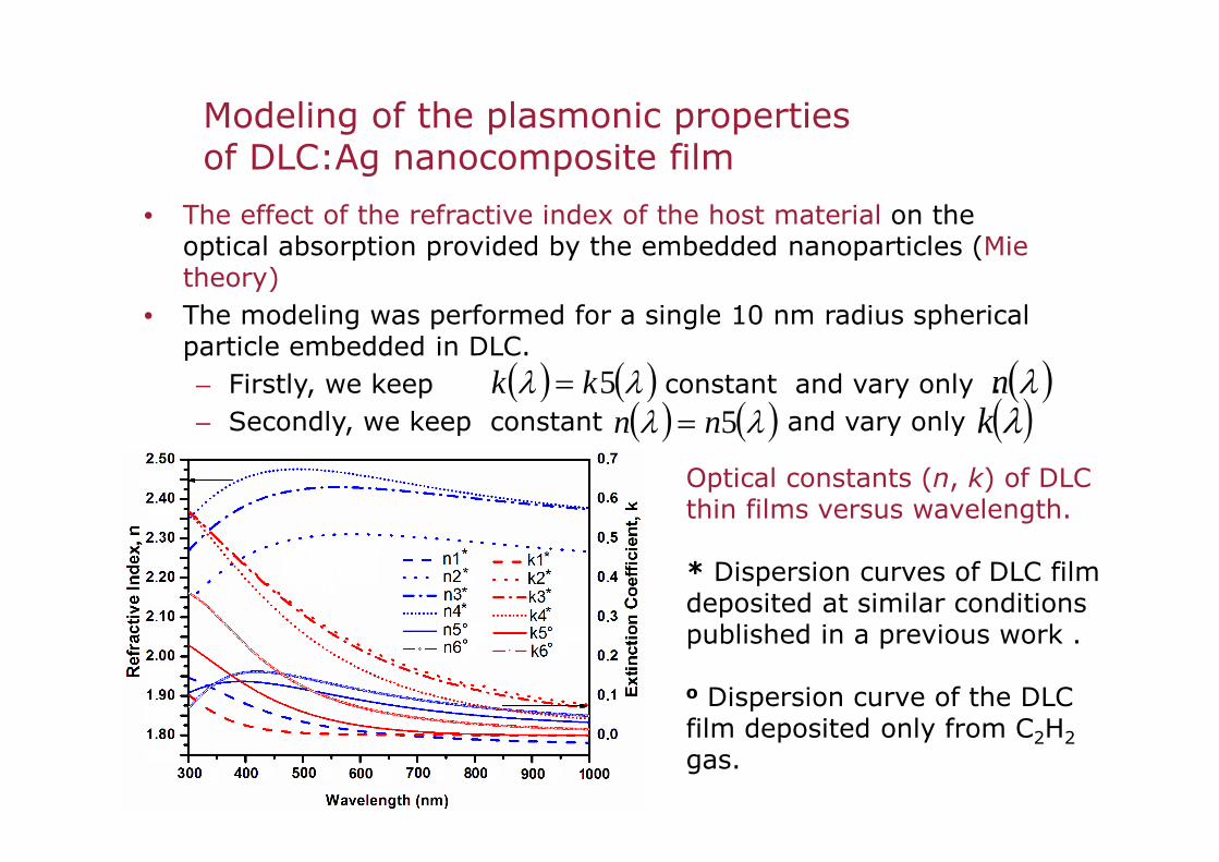
• The effect of the refractive index of the host material on the optical absorption provided by the embedded nanoparticles (Mie theory)
• The modeling was performed for a single 10 nm radius spherical particle embedded in DLC. – Firstly, we keep constant and vary only . – Secondly, we keep constant and vary only
.
( ) ( )λλ 5kk = ( )λn( ) ( )λλ 5nn = ( )λk
Optical constants (n, k) of DLC thin films versus wavelength.
* Dispersion curves of DLC film deposited at similar conditions published in a previous work .
o Dispersion curve of the DLC film deposited only from C2H2 gas.

Modeling of the plasmonic properties of DLC:Ag nanocomposite film
• Decrease of refractive index value of the host medium leads to blue shift and increase of the intensity of absorption peak that is in line with the quasi-static model of particle scattering;
• The amplitude of the absorption peak decreases as increases due to decreasing polarizability of the nanoparticlesand reduced interaction between them
k
Effect of the DLC host medium versus wavelength on the absorption cross section of 10 nm radius Ag particle (Mie th.)

Modeling of the plasmonic properties of DLC:Ag nanocomposite film
• Resonance responses of the silver nanoparticles for dielectric constants of DLC n(λ) = n5(λ) and k(λ) = k5(λ) on the radius and wavelength (Mie theory).
Spectral position of the absorption cross-section is sensitive:- to the tunable dielectric
constant of DLC and- to the radius of
nanoparticles.
Effect of the radius Ag particle (Mie theory) andwavelength on the absorption cross section

Modeling of the plasmonic properties of DLC:Ag nanocomposite film
• According to effective medium theory proposed by Maxwell–Garnett for material comprised of two or more constituents or phases effective permittivity of the composite:
• The absorption maximum occurs at the wavelength that satisfies the eq.:
• The effective permittivity for two components including the size effect:
( ) ( )( ) ( )ff
ff
hm
hmheff ++−
−++=
21
1221
εεεε
εε , f - filling factor of the medium εm
( ) ( ) 021 =++− ff hm εε
( ) ( ) ( )( )( ) ( ) ( )( )∆−−+++−
∆−−+−++=
fff
fff
mhhm
mhhmheff 121
11221
εεεεεεεε
εε
λπ
εR
x
ixx
2
,32
2
32
=
+=∆
R. Ruppin. Opt. Commun. 182, 273 (2000)

Modeling of the plasmonic properties of DLC:Ag nanocomposite film
• The Maxwell–Garnett theory has been used to describe the localized surface plasmon resonance− The inclusions are assumed to have spherical shape and uniform
size− The size is much less than the typical separation between them
and that such separation is much less than the wavelength of the probing light
• The relationship between the optical absorption coefficient αand the effective dielectric constant:
•Where and are the real and imaginary parts the effective dielectric constant, respectively .
( )2/12/122
2/1
2
14
−+
= RIR εεελπ
α
Rε Iε
I.Yaremchuk, A.Tamulevičienė, T.Tamulevičius, K. Šlapikas, Z. Balevičius, S. Tamulevičius, Physica Status Solidi (a)-Applications and Materials. 2014, Vol. 211, no. 2, p. 329-335

Modeling of the plasmonic properties of DLC:Ag nanocomposite film
• Simulated effective (a) real and (b) imaginary part of a DLC–Ag composite dielectric function employing Maxwell- Garnett theory
Experimentally optical constants were measured for DLC-Ag nanocomposite with 20 at% of silver nanoparticles(that corresponds to the filling factor f=0.20)

Modeling of the plasmonic properties of DLC:Ag nanocomposite film
• Spectra of the effective refractive index (a) and the extinction coefficient (b) of DLC-Ag film obtained by calculation for concentration of Ag 6.7% and different radius of silver nanoparticles
I. Yaremchuk, A. Tamulevičienė, T. Tamulevičius, S. TamulevičiusApplied Mechanics and Materials Vols. 490-491 (2014) pp 53-57
,

Modeling of the plasmonic properties of DLC:Ag nanocomposite film
• Spectra of effective refractive index (neff) and extinction coefficient (keff) of DLC-Ag film obtained by calculation (line) and regression analysis of experimental ellipsometrydata (points)

Modeling of the plasmonic properties of DLC:Ag nanocomposite film
SEM microgragh of DLC-Ag nanocomposite (a) and size distribution of Ag nanoparticles (b)
Experimental and calculated optical absorption spectra of DLC-Ag thin film( 20 at% of silver nanoparticles)

Structuring of DLC:Ag nanocompositethin films
• DLC:Ag films were deposited employing unbalanced reactive magnetron sputtering of silver target with Ar+ in C2H2 gas atmosphere. Films with different silver content (0.6-12.9 at.%) were analyzed.
Sample Ar gas flux
(sccm)
C2H2 gas flux
(sccm)
C2H2/Ar flux ratio
(%)
Magnetron target current,
I (A) U (V)
Deposition time
t (mm:ss) No. 1 70 21.1 30 0.07-0.12 553-625 8:40 No. 2 70 21.1 30 0.08-0.17 553-625 4:40 No. 3 70 21.1 30 0.07-0.22 568-741 3:55 No. 4 80 7.8 10 0.1-0.11 625-656 3:20
SampleConcentration (at.%)
Ag/C ratioCalculated
thickness (nm)C Ag O
No. 1 92.4 0.6 6.9 0.0065 266No. 2 88.6 2.1 9.3 0.0237 253No. 3 84.3 5.8 9.9 0.0688 222No. 4 75.2 12.9 11.9 0.1715 181
Structuring of DLC:Ag nanocompositethin films
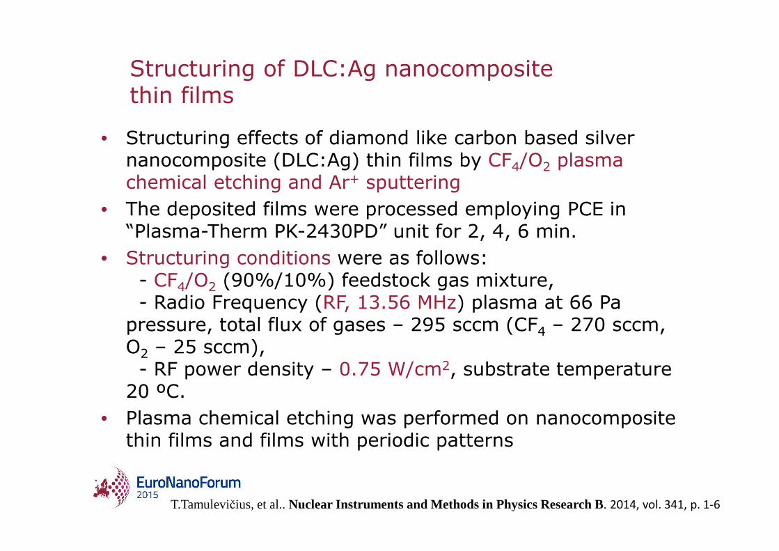
• Structuring effects of diamond like carbon based silver nanocomposite (DLC:Ag) thin films by CF4/O2 plasma chemical etching and Ar+ sputtering
• The deposited films were processed employing PCE in “Plasma-Therm PK-2430PD” unit for 2, 4, 6 min.
• Structuring conditions were as follows: - CF4/O2 (90%/10%) feedstock gas mixture, - Radio Frequency (RF, 13.56 MHz) plasma at 66 Pa
pressure, total flux of gases – 295 sccm (CF4 – 270 sccm, O2 – 25 sccm), - RF power density – 0.75 W/cm2, substrate temperature
20 ºC. • Plasma chemical etching was performed on nanocomposite
thin films and films with periodic patterns
T.Tamulevičius, et al.. Nuclear Instruments and Methods in Physics Research B. 2014, vol. 341, p. 1-6

Structuring of DLC:Ag nanocompositethin films
Normalized particle size distribution together with log normal distribution fit after different PCE processing durations (2-6 min) of the sample No. 3
SEM micrographs of different silver content films (samples No. 1-4, concentration of Ag 0.6-12.9 at.%) after different processing durations.

Structuring of DLC:Ag nanocompositethin films
Sample
Mean particle diameter d (nm) with a standard deviation after
PCE treatment
2 min 4 min 6 min
No. 1 12±7 10±2 9±1
No. 2 26±13 13±4 14±5
No. 3 14±5 25±19 30±24
No. 4 68±79 27±52 189±112
After PCE processing of the films, the samples have demonstrated different behavior depending on the silver content in the film:
Films with the lowest silver content (samples No. 1-2) demonstrated only minimal changes of the silver cluster size after different processing durations;
Samples containing more than 5 at.% of silver (No. 3-4) demonstrated different behavior. After PCE processing, silver particles/clusters tended to agglomerate into 26-190 nm diameter spheres

Structuring of DLC:Ag nanocompositethin films
a b c d e
Optical microscope (a, b) and SEM (c, d, e) micrographs of 4 µm period diffraction grating structures dry etched in DLC:Ag film (sample No. 3) employing different processing recipes depicted in the insets. Micrographs presents etched patterns with mask (a, b)and without mask (c-e). Al and PhR stands for aluminum and photoresist masks respectively. Scale bar 10 µm.

DLC:Ag based sensor fabrication roadmap
DLC:Ag coating on glass substrate (Reactive Magnetron sputtering) Spincoating of UL1 and SiPOL
NIL
RIE of SiPol residual layer with CHF3 and CF4
RIE of UL1 transfer layer and DLC:Agwith O2 plasma
Removal of remaining SiPol and UL1 isopropanol,etching the surface of DLC:Ag with O2 plasma
SIPOL is a silicon-containing thermal nanoimprint resist with a high oxygen plasma resistanceUL1 transfer layer material.
Imprints can be performed at moderate temperatures in the range of 110 – 140 °C.

Etched with RF plasma: RF=40W, p=150mTorr, t=6min
Etching of DLC:Ag nanocomposite

Reflectance spectra for the DLC:Ag based diffraction grating (RCWA)
• The geometrical parameters of the gratings:– period 428 nm; – the grating depth and waveguide thickness 75 nm and
155 nm, respectively. • The DLC-Ag thin film included spherical nanoparticles of Ag
with radius 5 nm. (0, 2 and 6.7at %Ag)
I. Yaremchuk, A. Tamulevičienė, T. Tamulevičius, S. TamulevičiusApplied Mechanics and Materials Vols. 490-491 (2014) pp 53-57
,

Summary
• DLC can be used efficiently as a functional material for optical and piezoresistive applications
• Properties of DLC (refractive index, absortion coefficient) can be tuned in a wide range using different transport gas and precursor
• Additional doping of the HMDS vapor by N2 or Ar gas during the ion beam synthesis process results in increased optical transmittance in UV range
• The extended Maxwell–Garnett effective theory, which includes size effect, can be successfully applied to describe the optical properties of actual DLC nanocomposite films with the concentration of Ag nanoparticles up to 20 at%.
• A random mixture consisting of a DLC film with embedded isolated silver inclusions is promising material for the fabrication of tunable nanocomposites that could used in different sensing platforms employing surface plasmonresonance

•
Thank you for your kind attention