diamond da 40 & da 40 f - garmin internationalstatic.garmin.com/pumac/g1000:diamond_post... ·...
TRANSCRIPT
190-00544-00 June, 2007 Revision G
G1000 Post Installation Checkout Diamond DA 40 & DA 40 F
FAA STC #SA01254WI-D
Page A G1000 Post Installation Checkout - Diamond DA 40& DA 40 F Revision G 190-00544-00
© Copyright 2007 Garmin Ltd. or its subsidiaries
All Rights Reserved Except as expressly provided herein, no part of this manual may be reproduced, copied, transmitted, disseminated, downloaded or stored in any storage medium, for any purpose without the express prior written consent of Garmin. Garmin hereby grants permission to download a single copy of this manual and of any revision to this manual onto a hard drive or other electronic storage medium to be viewed and to print one copy of this manual or of any revision hereto, provided that such electronic or printed copy of this manual or revision must contain the complete text of this copyright notice and provided further that any unauthorized commercial distribution of this manual or any revision hereto is strictly prohibited.
Garmin International, Inc. 1200 E. 151st Street
Olathe, KS 66062 USA Telephone: 913-397-8200
www.garmin.com
Garmin (Europe) Ltd. Liberty House, Bulls Copse Road
Hounsdown Business Park Southampton, SO40 9RB, UK Phone: +44 (0) 23 8052 4000
Fax: +44 (0) 23 8052 4004
RECORD OF REVISIONS
Revision Revision Date Description ECO #1 2/18/2005 Initial release for STC Configuration 1 ------- 2 3/21/2005 Final markups for STC. 30311 3 4/21/2005 Add Field Update Instructions 30826 A 6/01/2005 Update document for DA 40 F 31529 B 8/25/2005 Update for STC Configuration 2 32938 C 10/12/2005 Update for STC Configuration 3 33790 D 3/6/2006 Update for EASA Validation 36416 E 4/19/06 Update for STC Configuration 4 37385 F 10/23/2006 Add system software 0369.12 to Section 1.1 40661 G 6/4/2007 Add –D to STC Number for DAS Incorporation 44779
DOCUMENT PAGINATION
Section Pagination Table of Contents
i – iv
Section 1 1-1 – 1-10 Section 2 2-1 – 2-42 Section 3 3-1 – 3-30 Section 4 4-1 – 4-2
G1000 Post Installation Checkout - Diamond DA 40 & DA 40 F Page i 190-00544-00 Revision G
INFORMATION SUBJECT TO EXPORT CONTROL LAWS
This document may contain information which is subject to the Export Administration Regulations ("EAR") issued by the United States Department of Commerce (15 CFR, Chapter VII, Subchapter C) and which may not be exported, released, or disclosed to foreign nationals inside or outside of the United States without first obtaining an export license. A violation of the EAR may be subject to a penalty of up to 10 years imprisonment and a fine of up to $1,000,000 under Section 2410 of the Export Administration Act of 1979. Include this notice with any reproduced portion of this document.
This product, its packaging, and its components contain chemicals known to the State of California to cause cancer, birth defects, or reproductive harm. This Notice is being provided in accordance with California's Proposition 65. If you have any questions or would like additional information, please refer to our web site at www.garmin.com/prop65.
The GDU 1040s use a lens coated with a special anti-reflective coating that is very sensitive to skin oils, waxes and abrasive cleaners. CLEANERS CONTAINING AMMONIA WILL HARM THE ANTI-REFLECTIVE COATING. It is very important to clean the lens using a clean, lint-free cloth and an eyeglass lens cleaner that is specified as safe for anti-reflective coatings
All G1000 screen shots used in this document are current at the time of initial publication. Screen shots are intended to provide visual reference only. All information depicted in screen shots, including software file names, versions and part numbers, is subject to change and may not be up to date.
All references to Diamond DA 40 aircraft made in this manual equally apply to Diamond DA 40 F aircraft, unless otherwise noted.
CAUTION
WARNING
IMPORTANT
IMPORTANT

Page ii G1000 Post Installation Checkout - Diamond DA 40 & DA 40 F Revision G 190-00544-00
This page intentionally left blank
G1000 Post Installation Checkout - Diamond DA 40 & DA 40 F Page iii 190-00544-00 Revision G
TABLE OF CONTENTS PARAGRAPH PAGE
1 INTRODUCTION 1-1 1.1 Scope..................................................................................................................................................1-1 1.2 Organization.......................................................................................................................................1-1 1.3 Reference Documents ........................................................................................................................1-2 1.4 System Description ............................................................................................................................1-3 1.5 G1000 System Communication .........................................................................................................1-4 1.6 G1000 Control Interface ....................................................................................................................1-6 2 POST INSTALLATION PROCEDURES 2-1 2.1 Required Test Equipment...................................................................................................................2-1 2.2 G1000 Hardware/Software Compatibility Check ..............................................................................2-1 2.3 G1000 Software/Configuration Procedure.........................................................................................2-2 2.4 Final Configuration Items ................................................................................................................2-16 2.5 Software Load Confirmation............................................................................................................2-33 2.6 Fuel Quantity Transducer Calibration..............................................................................................2-34 2.7 Software/Configuration Troubleshooting ........................................................................................2-40 3 SYSTEM TESTING & CHECKOUT 3-1 3.1 Initial Display Testing........................................................................................................................3-1 3.2 GMA 1347 Testing ..........................................................................................................................3-10 3.3 GIA 63 Testing.................................................................................................................................3-11 3.4 GTX 33 Testing ...............................................................................................................................3-12 3.5 GDC 74A TESTING........................................................................................................................3-13 3.6 GRS 77/GMU 44 Initial Alignment .................................................................................................3-15 3.7 Engine Start......................................................................................................................................3-17 3.8 Final GRS 77/GMU 44 Calibration Procedures...............................................................................3-18 3.9 KAP 140 Alignment (optional) ........................................................................................................3-26 3.10 Final System Checkout ....................................................................................................................3-27 4 G1000 TAWS FLIGHT TEST PROCEDURE 4-1 4.1 TAWS ‘FIVE HUNDRED’ Call-out (if TAWS is activated)............................................................4-1
Page iv G1000 Post Installation Checkout - Diamond DA 40 & DA 40 F Revision G 190-00544-00
LIST OF ILLUSTRATIONS FIGURE PAGE FIGURE 1-1. G1000 SYSTEM INTERFACE .........................................................................................1-4 FIGURE 1-2. EIS INTERFACE...............................................................................................................1-4 FIGURE 1-3. FLIGHT INSTRUMENTATION INTERFACE................................................................1-5 FIGURE 1-4. GDU 1040 CONTROL INTERFACE ...............................................................................1-6 FIGURE 1-5. GDU SOFTKEYS..............................................................................................................1-7 FIGURE 1-6. CONFIGURATION MODE NAVIGATOR......................................................................1-8 FIGURE 1-7. GMA 1347 CONTROL INTERFACE...............................................................................1-9 FIGURE 2-1. SOFTWARE/CONFIGURATION OVERVIEW ..............................................................2-2 FIGURE 3-1. MFD POWER UP PAGE...................................................................................................3-1 FIGURE 3-2. PFD POWER-UP SYSTEM ANNUNCIATIONS ............................................................3-2 FIGURE 3-3. FUEL PRESSURE GAUGE CHECK................................................................................3-3 FIGURE 3-4. 3RD AUX PAGE (MFD).....................................................................................................3-9 FIGURE 3-5. MARKER BEACON SYMBOLOGY .............................................................................3-10 FIGURE 3-6. ENGINE/AIRFRAME INDICATORS (ENGINE, LEAN, & SYSTEM) .......................3-17 FIGURE 3-7. AHRS INFORMATION VALID.....................................................................................3-22 FIGURE 3-8. REVERSIONARY MODE AHRS INFORMATION......................................................3-22 FIGURE 3-9. MAGNETOMETER INTERFERENCE TEST ...............................................................3-23
LIST OF TABLES TABLE PAGE TABLE 1-1. REFERENCED DOCUMENTATION................................................................................1-2 TABLE 3-1. MAGNETOMETER INTERFERENCE TEST SEQUENCE (EXAMPLE).....................3-24
G1000 Post Installation Checkout - Diamond DA 40 & DA 40 F Page 1-1 190-00544-00 Revision G
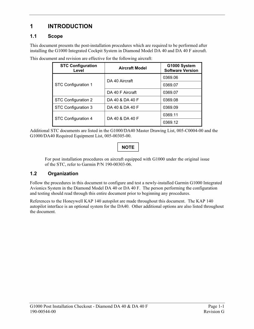
1 INTRODUCTION 1.1 Scope
This document presents the post-installation procedures which are required to be performed after installing the G1000 Integrated Cockpit System in Diamond Model DA 40 and DA 40 F aircraft.
This document and revision are effective for the following aircraft: STC Configuration
Level Aircraft Model G1000 System Software Version
0369.06 DA 40 Aircraft
0369.07 STC Configuration 1
DA 40 F Aircraft 0369.07
STC Configuration 2 DA 40 & DA 40 F 0369.08
STC Configuration 3 DA 40 & DA 40 F 0369.09
0369.11 STC Configuration 4 DA 40 & DA 40 F
0369.12
Additional STC documents are listed in the G1000/DA40 Master Drawing List, 005-C0004-00 and the G1000/DA40 Required Equipment List, 005-00305-00.
For post installation procedures on aircraft equipped with G1000 under the original issue of the STC, refer to Garmin P/N 190-00303-06.
1.2 Organization
Follow the procedures in this document to configure and test a newly-installed Garmin G1000 Integrated Avionics System in the Diamond Model DA 40 or DA 40 F. The person performing the configuration and testing should read through this entire document prior to beginning any procedures.
References to the Honeywell KAP 140 autopilot are made throughout this document. The KAP 140 autopilot interface is an optional system for the DA40. Other additional options are also listed throughout the document.
NOTE
Page 1-2 G1000 Post Installation Checkout - Diamond DA 40 & DA 40 F Revision G 190-00544-00
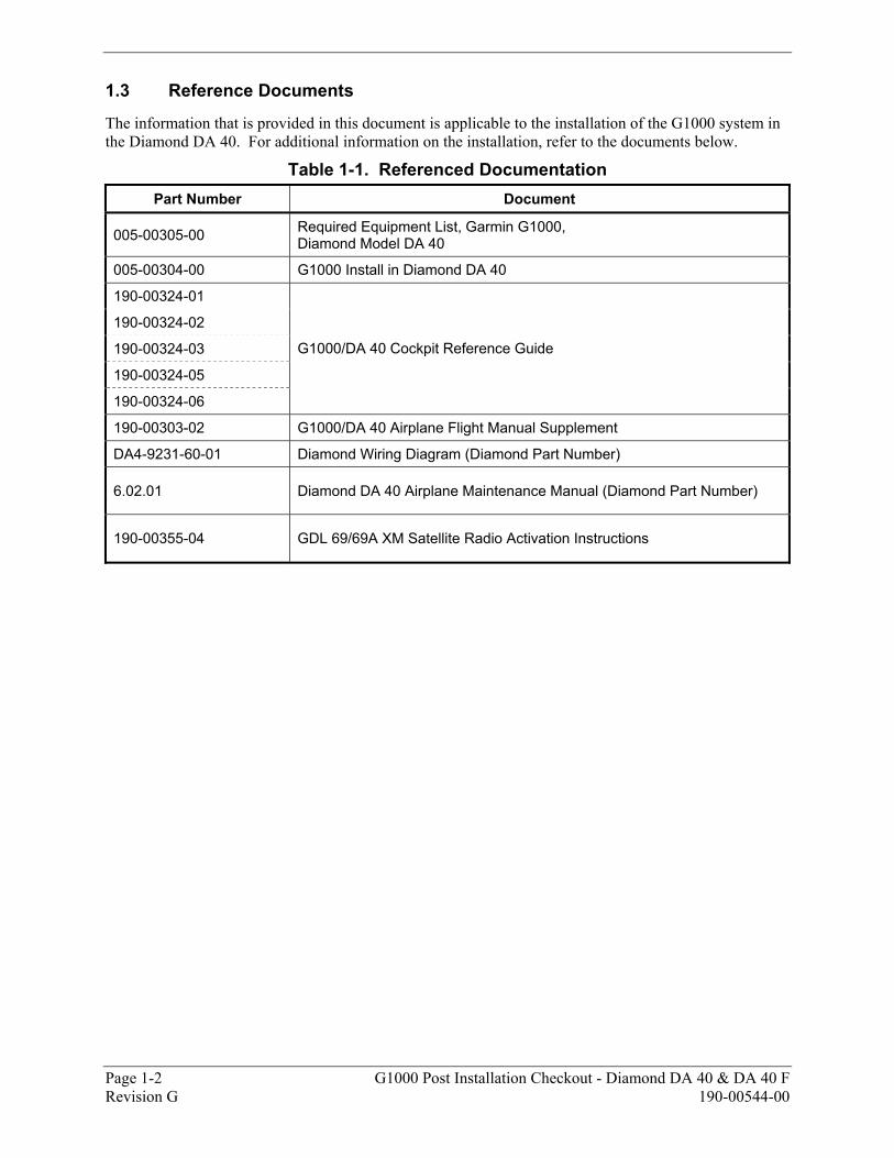
1.3 Reference Documents
The information that is provided in this document is applicable to the installation of the G1000 system in the Diamond DA 40. For additional information on the installation, refer to the documents below.
Table 1-1. Referenced Documentation Part Number Document
005-00305-00 Required Equipment List, Garmin G1000, Diamond Model DA 40
005-00304-00 G1000 Install in Diamond DA 40
190-00324-01
190-00324-02
190-00324-03
190-00324-05
190-00324-06
G1000/DA 40 Cockpit Reference Guide
190-00303-02 G1000/DA 40 Airplane Flight Manual Supplement
DA4-9231-60-01 Diamond Wiring Diagram (Diamond Part Number)
6.02.01 Diamond DA 40 Airplane Maintenance Manual (Diamond Part Number)
190-00355-04 GDL 69/69A XM Satellite Radio Activation Instructions
G1000 Post Installation Checkout - Diamond DA 40 & DA 40 F Page 1-3 190-00544-00 Revision G
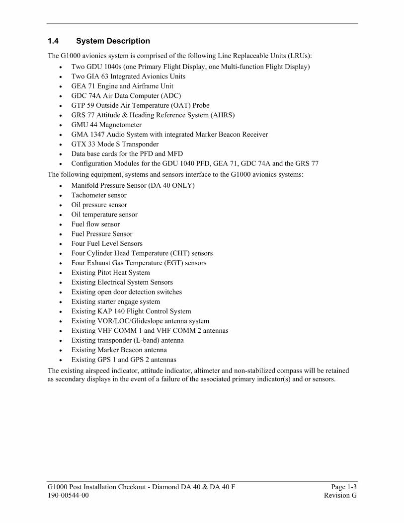
1.4 System Description
The G1000 avionics system is comprised of the following Line Replaceable Units (LRUs): • Two GDU 1040s (one Primary Flight Display, one Multi-function Flight Display) • Two GIA 63 Integrated Avionics Units • GEA 71 Engine and Airframe Unit • GDC 74A Air Data Computer (ADC) • GTP 59 Outside Air Temperature (OAT) Probe • GRS 77 Attitude & Heading Reference System (AHRS) • GMU 44 Magnetometer • GMA 1347 Audio System with integrated Marker Beacon Receiver • GTX 33 Mode S Transponder • Data base cards for the PFD and MFD • Configuration Modules for the GDU 1040 PFD, GEA 71, GDC 74A and the GRS 77
The following equipment, systems and sensors interface to the G1000 avionics systems: • Manifold Pressure Sensor (DA 40 ONLY) • Tachometer sensor • Oil pressure sensor • Oil temperature sensor • Fuel flow sensor • Fuel Pressure Sensor • Four Fuel Level Sensors • Four Cylinder Head Temperature (CHT) sensors • Four Exhaust Gas Temperature (EGT) sensors • Existing Pitot Heat System • Existing Electrical System Sensors • Existing open door detection switches • Existing starter engage system • Existing KAP 140 Flight Control System • Existing VOR/LOC/Glideslope antenna system • Existing VHF COMM 1 and VHF COMM 2 antennas • Existing transponder (L-band) antenna • Existing Marker Beacon antenna • Existing GPS 1 and GPS 2 antennas
The existing airspeed indicator, attitude indicator, altimeter and non-stabilized compass will be retained as secondary displays in the event of a failure of the associated primary indicator(s) and or sensors.
Page 1-4 G1000 Post Installation Checkout - Diamond DA 40 & DA 40 F Revision G 190-00544-00
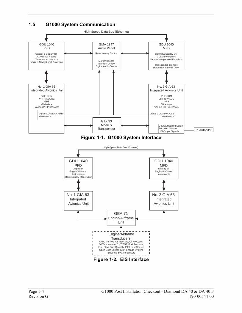
1.5 G1000 System Communication
GDU 1040PFD
Control & Display Of: COM/NAV Radios
Transponder InterfaceVarious Navigational Functions
GDU 1040MFD
Control & Display Of: COM/NAV Radios
Various Navigational Functions
Transponder Interface(Reversionar Mode Only)
GMA 1347Audio Panel
No. 1 GIA 63 Integrated Avionics Unit
VHF COMVHF NAV/LOC
GPSGlideslope
Various I/O Processors
No. 2 GIA 63 Integrated Avionics Unit
VHF COMVHF NAV/LOC
GPSGlideslope
Various I/O Processors
GTX 33Mode S
Transponder
High-Speed Data Bus (Ethernet)
To Autopilot
Reversionary Control
Course/Heading DatumEncoded AltitudeHSI Output Signals
Digital COM/NAV AudioVoice Alerts
Digital COM/NAV AudioVoice Alerts
Marker BeaconIntercom Control
Digital Audio Control
Figure 1-1. G1000 System Interface
GDU 1040PFD
Display of Engine/Airframe
Instruments(Reversionary Mode Only)
GDU 1040MFD
Display of Engine/Airframe
Instruments
No. 1 GIA 63 Integrated
Avionics Unit
No. 2 GIA 63 Integrated
Avionics Unit
GEA 71Engine/Airframe
Unit
Engine/AirframeTransducers:
RPM, Manifold Air Pressure, Oil Pressure, Oil Temperature, CHT/EGT, Fuel Pressure,Fuel Flow, Fuel Quantity, Pitot Heat Sensor,Open Door Sensor, Start Engage System,
Electrical System Sensors
High-Speed Data Bus (Ethernet)
Figure 1-2. EIS Interface
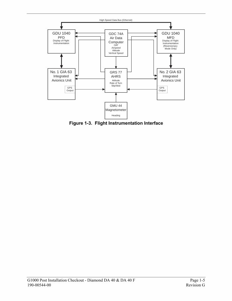
G1000 Post Installation Checkout - Diamond DA 40 & DA 40 F Page 1-5 190-00544-00 Revision G
GDU 1040PFD
Display of Flight Instrumentation
GDU 1040MFD
Display of Flight Instrumentation(Reversionary
Mode Only)
No. 1 GIA 63 Integrated
Avionics Unit
No. 2 GIA 63 Integrated
Avionics Unit
GDC 74AAir Data
ComputerOAT
AirspeedAltitude
Vertical Speed
GRS 77AHRSAttitude
Rate of TurnSlip/Skid
GMU 44Magnetometer
Heading
GPS Output
GPS Output
High-Speed Data Bus (Ethernet)
Figure 1-3. Flight Instrumentation Interface
Page 1-6 G1000 Post Installation Checkout - Diamond DA 40 & DA 40 F Revision G 190-00544-00
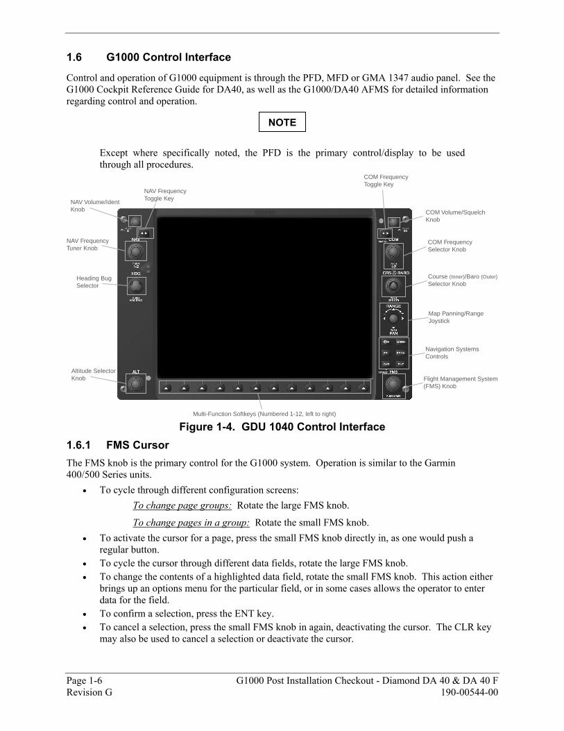
1.6 G1000 Control Interface
Control and operation of G1000 equipment is through the PFD, MFD or GMA 1347 audio panel. See the G1000 Cockpit Reference Guide for DA40, as well as the G1000/DA40 AFMS for detailed information regarding control and operation.
Except where specifically noted, the PFD is the primary control/display to be used through all procedures.
COM Frequency Toggle Key
COM Frequency Selector Knob
Course (Inner)/Baro (Outer)Selector Knob
Map Panning/RangeJoystick
Navigation SystemsControls
Flight Management System(FMS) Knob
Multi-Function Softkeys (Numbered 1-12, left to right)
NAV Frequency Toggle Key
NAV Frequency Tuner Knob
Heading Bug Selector
NAV Volume/IdentKnob
Altitude SelectorKnob
COM Volume/SquelchKnob
Figure 1-4. GDU 1040 Control Interface
1.6.1 FMS Cursor The FMS knob is the primary control for the G1000 system. Operation is similar to the Garmin 400/500 Series units.
• To cycle through different configuration screens: To change page groups: Rotate the large FMS knob.
To change pages in a group: Rotate the small FMS knob. • To activate the cursor for a page, press the small FMS knob directly in, as one would push a
regular button. • To cycle the cursor through different data fields, rotate the large FMS knob. • To change the contents of a highlighted data field, rotate the small FMS knob. This action either
brings up an options menu for the particular field, or in some cases allows the operator to enter data for the field.
• To confirm a selection, press the ENT key. • To cancel a selection, press the small FMS knob in again, deactivating the cursor. The CLR key
may also be used to cancel a selection or deactivate the cursor.
NOTE

G1000 Post Installation Checkout - Diamond DA 40 & DA 40 F Page 1-7 190-00544-00 Revision G
1.6.2 Softkeys Some configuration pages have commands or selections that are activated by the GDU 1040 softkeys. If a softkey is associated with a command, that command will be displayed directly above the key. A grayed-out softkey shows a command that is unavailable. Also, a softkey that is highlighted shows the current active selection.
Figure 1-5. GDU Softkeys
1.6.3 Starting Configuration Mode To complete this aircraft checkout, a basic understanding of the G1000 configuration mode is required. The configuration mode allows a technician to access certain areas of the system in order to carry out various configurations, calibrations, and checks.
1. To start a GDU 1040 in configuration mode, hold down the ENT key while applying power.
2. Continue to hold the ENT key until the white letters INITIALIZING SYSTEM appear in the upper left corner of the display.

Page 1-8 G1000 Post Installation Checkout - Diamond DA 40 & DA 40 F Revision G 190-00544-00
The following diagram lists the various page groups and pages shown in the G1000 configuration mode.
1. System Status Page2. Date/Time Setup page3. Main Lighting Page4. Audio Alert Configuration Page5. Software Upload Page
6. Configuration Upload Page7. System Configuration Page8. Manifest Configuration Page
1. RS-232 / ARINC 429 Config Page2. GDU Status Page3. GDU Test Page4. Serial/Ethernet I/O Page
5. Alert Configuration Page6. Airframe Configuration Page
1. RS-232 / ARINC 429 Config Page2. CAN / RS-485 Config Page3. GIA I/O Configuration Page4. COM Setup Page5. GIA Status Page
1. Engine Data Page2. GEA Status Page3. Fuel Calibration Page4. GEA Configuration Page5. Fuel Tank Configuration Page
1. RS-232 / ARINC 429 Config Page2. Transponder Configuration Page
1. AHRS / Air Data Input Page2. GRS / GMU Calibration Page
1. GDC Configuration Page
1. GMA Configuration Page
1. Stormscope Configuration Page
Figure 1-6. Configuration Mode Navigator
G1000 Post Installation Checkout - Diamond DA 40 & DA 40 F Page 1-9 190-00544-00 Revision G
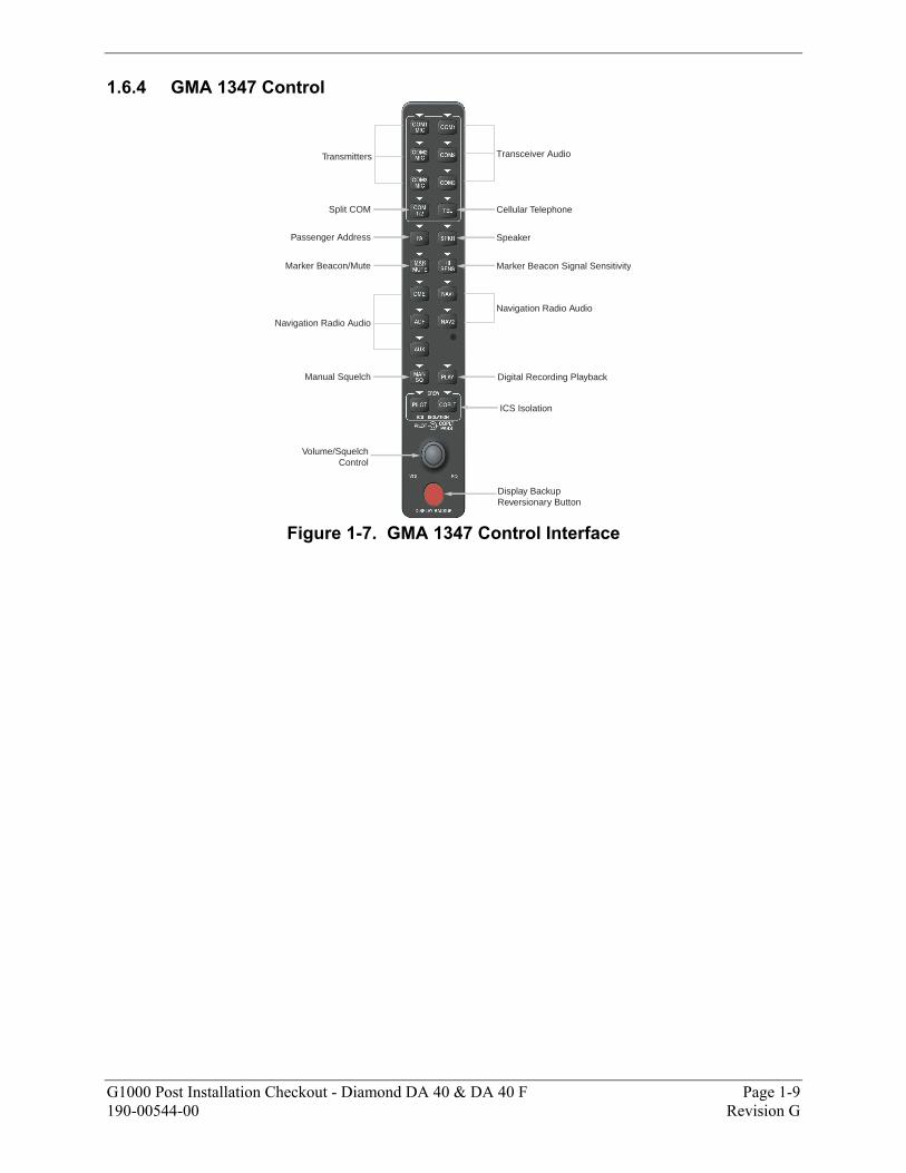
1.6.4 GMA 1347 Control
Display BackupReversionary Button
Volume/SquelchControl
ICS Isolation
Digital Recording PlaybackManual Squelch
Navigation Radio Audio
Navigation Radio Audio
Marker Beacon Signal SensitivityMarker Beacon/Mute
SpeakerPassenger Address
Split COM
Transmitters Transceiver Audio
Cellular Telephone
Figure 1-7. GMA 1347 Control Interface

Page 1-10 G1000 Post Installation Checkout - Diamond DA 40 & DA 40 F Revision G 190-00544-00
This page intentionally left blank.
G1000 Post Installation Checkout - Diamond DA 40 & DA 40 F Page 2-1 190-00544-00 Revision G
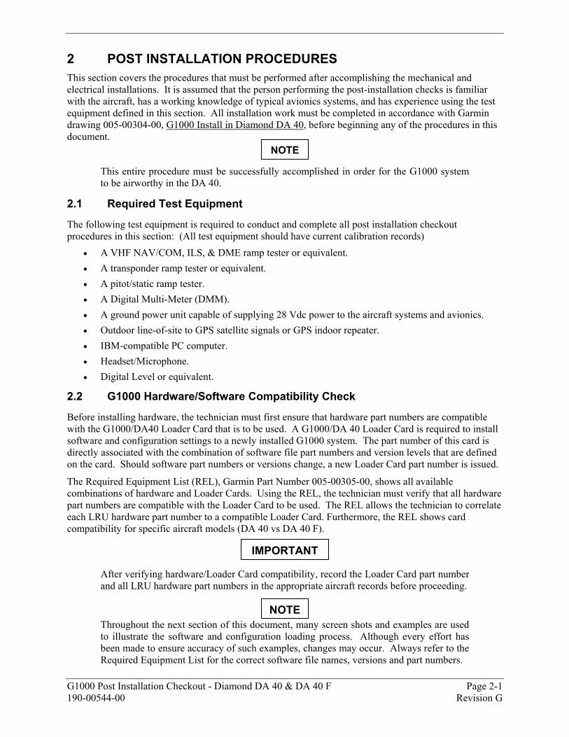
2 POST INSTALLATION PROCEDURES This section covers the procedures that must be performed after accomplishing the mechanical and electrical installations. It is assumed that the person performing the post-installation checks is familiar with the aircraft, has a working knowledge of typical avionics systems, and has experience using the test equipment defined in this section. All installation work must be completed in accordance with Garmin drawing 005-00304-00, G1000 Install in Diamond DA 40, before beginning any of the procedures in this document.
This entire procedure must be successfully accomplished in order for the G1000 system to be airworthy in the DA 40.
2.1 Required Test Equipment
The following test equipment is required to conduct and complete all post installation checkout procedures in this section: (All test equipment should have current calibration records)
• A VHF NAV/COM, ILS, & DME ramp tester or equivalent. • A transponder ramp tester or equivalent. • A pitot/static ramp tester. • A Digital Multi-Meter (DMM). • A ground power unit capable of supplying 28 Vdc power to the aircraft systems and avionics. • Outdoor line-of-site to GPS satellite signals or GPS indoor repeater. • IBM-compatible PC computer. • Headset/Microphone. • Digital Level or equivalent.
2.2 G1000 Hardware/Software Compatibility Check
Before installing hardware, the technician must first ensure that hardware part numbers are compatible with the G1000/DA40 Loader Card that is to be used. A G1000/DA 40 Loader Card is required to install software and configuration settings to a newly installed G1000 system. The part number of this card is directly associated with the combination of software file part numbers and version levels that are defined on the card. Should software part numbers or versions change, a new Loader Card part number is issued.
The Required Equipment List (REL), Garmin Part Number 005-00305-00, shows all available combinations of hardware and Loader Cards. Using the REL, the technician must verify that all hardware part numbers are compatible with the Loader Card to be used. The REL allows the technician to correlate each LRU hardware part number to a compatible Loader Card. Furthermore, the REL shows card compatibility for specific aircraft models (DA 40 vs DA 40 F).
After verifying hardware/Loader Card compatibility, record the Loader Card part number and all LRU hardware part numbers in the appropriate aircraft records before proceeding.
Throughout the next section of this document, many screen shots and examples are used to illustrate the software and configuration loading process. Although every effort has been made to ensure accuracy of such examples, changes may occur. Always refer to the Required Equipment List for the correct software file names, versions and part numbers.
NOTE
IMPORTANT
NOTE
Page 2-2 G1000 Post Installation Checkout - Diamond DA 40 & DA 40 F Revision G 190-00544-00
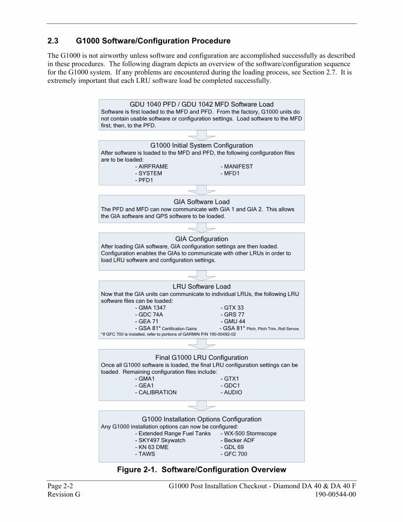
2.3 G1000 Software/Configuration Procedure
The G1000 is not airworthy unless software and configuration are accomplished successfully as described in these procedures. The following diagram depicts an overview of the software/configuration sequence for the G1000 system. If any problems are encountered during the loading process, see Section 2.7. It is extremely important that each LRU software load be completed successfully.
GDU 1040 PFD / GDU 1042 MFD Software Load
Software is first loaded to the MFD and PFD. From the factory, G1000 units do not contain usable software or configuration settings. Load software to the MFD first; then, to the PFD.
G1000 Installation Options ConfigurationAny G1000 installation options can now be configured:
- Extended Range Fuel Tanks - WX-500 Stormscope - SKY497 Skywatch - Becker ADF- KN 63 DME - GDL 69- TAWS - GFC 700
LRU Software LoadNow that the GIA units can communicate to individual LRUs, the following LRU software files can be loaded:
- GMA 1347 - GTX 33- GDC 74A - GRS 77- GEA 71 - GMU 44- GSA 81* Certification Gains - GSA 81* Pitch, Pitch Trim, Roll Servos
*If GFC 700 is installed, refer to portions of GARMIN P/N 190-00492-02
Final G1000 LRU ConfigurationOnce all G1000 software is loaded, the final LRU configuration settings can be loaded. Remaining configuration files include:
- GMA1 - GTX1- GEA1 - GDC1- CALIBRATION - AUDIO
GIA ConfigurationAfter loading GIA software, GIA configuration settings are then loaded. Configuration enables the GIAs to communicate with other LRUs in order to load LRU software and configuration settings.
G1000 Initial System ConfigurationAfter software is loaded to the MFD and PFD, the following configuration files are to be loaded:
- AIRFRAME - MANIFEST- SYSTEM - MFD1- PFD1
GIA Software LoadThe PFD and MFD can now communicate with GIA 1 and GIA 2. This allows the GIA software and GPS software to be loaded.
Figure 2-1. Software/Configuration Overview
G1000 Post Installation Checkout - Diamond DA 40 & DA 40 F Page 2-3 190-00544-00 Revision G
2.3.1 System Power Up Apply power to the G1000 by doing the following
1. Turn on the ground power unit, if utilized.
2. Turn on the BAT side master switch.
3. Turn on the AVIONICS MASTER switch. At this moment, all G1000 equipment is receiving power.
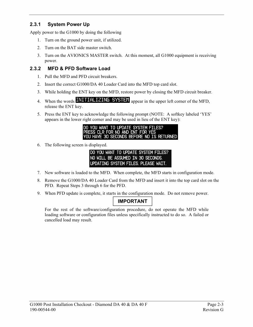
2.3.2 MFD & PFD Software Load 1. Pull the MFD and PFD circuit breakers.
2. Insert the correct G1000/DA 40 Loader Card into the MFD top card slot.
3. While holding the ENT key on the MFD, restore power by closing the MFD circuit breaker.
4. When the words appear in the upper left corner of the MFD, release the ENT key.
5. Press the ENT key to acknowledge the following prompt (NOTE: A softkey labeled ‘YES’ appears in the lower right corner and may be used in lieu of the ENT key):
6. The following screen is displayed.
7. New software is loaded to the MFD. When complete, the MFD starts in configuration mode.
8. Remove the G1000/DA 40 Loader Card from the MFD and insert it into the top card slot on the PFD. Repeat Steps 3 through 6 for the PFD.
9. When PFD update is complete, it starts in the configuration mode. Do not remove power.
For the rest of the software/configuration procedure, do not operate the MFD while loading software or configuration files unless specifically instructed to do so. A failed or cancelled load may result.
IMPORTANT
Page 2-4 G1000 Post Installation Checkout - Diamond DA 40 & DA 40 F Revision G 190-00544-00
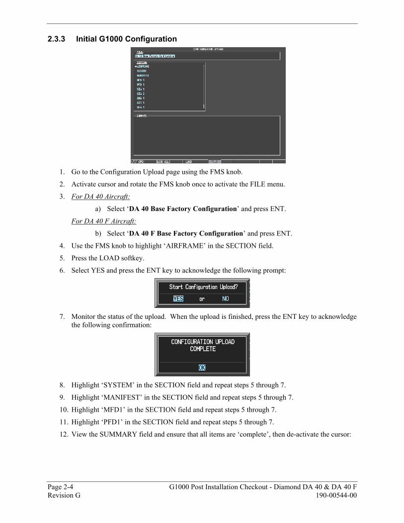
2.3.3 Initial G1000 Configuration
1. Go to the Configuration Upload page using the FMS knob.
2. Activate cursor and rotate the FMS knob once to activate the FILE menu.
3. For DA 40 Aircraft:
a) Select ‘DA 40 Base Factory Configuration’ and press ENT.
For DA 40 F Aircraft:
b) Select ‘DA 40 F Base Factory Configuration’ and press ENT.
4. Use the FMS knob to highlight ‘AIRFRAME’ in the SECTION field.
5. Press the LOAD softkey.
6. Select YES and press the ENT key to acknowledge the following prompt:
7. Monitor the status of the upload. When the upload is finished, press the ENT key to acknowledge
the following confirmation:
8. Highlight ‘SYSTEM’ in the SECTION field and repeat steps 5 through 7.
9. Highlight ‘MANIFEST’ in the SECTION field and repeat steps 5 through 7.
10. Highlight ‘MFD1’ in the SECTION field and repeat steps 5 through 7.
11. Highlight ‘PFD1’ in the SECTION field and repeat steps 5 through 7.
12. View the SUMMARY field and ensure that all items are ‘complete’, then de-activate the cursor:
G1000 Post Installation Checkout - Diamond DA 40 & DA 40 F Page 2-5 190-00544-00 Revision G
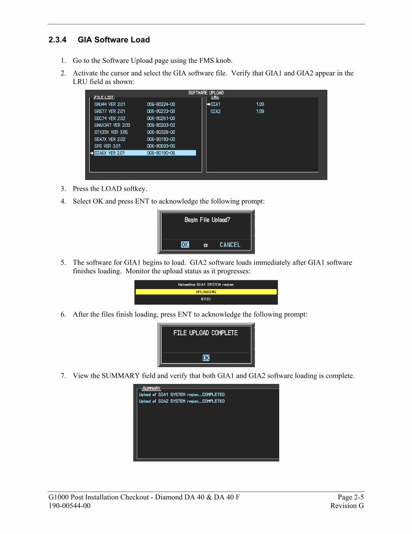
2.3.4 GIA Software Load
1. Go to the Software Upload page using the FMS knob.
2. Activate the cursor and select the GIA software file. Verify that GIA1 and GIA2 appear in the LRU field as shown:
3. Press the LOAD softkey.
4. Select OK and press ENT to acknowledge the following prompt:
5. The software for GIA1 begins to load. GIA2 software loads immediately after GIA1 software
finishes loading. Monitor the upload status as it progresses:
6. After the files finish loading, press ENT to acknowledge the following prompt:
7. View the SUMMARY field and verify that both GIA1 and GIA2 software loading is complete.
Page 2-6 G1000 Post Installation Checkout - Diamond DA 40 & DA 40 F Revision G 190-00544-00
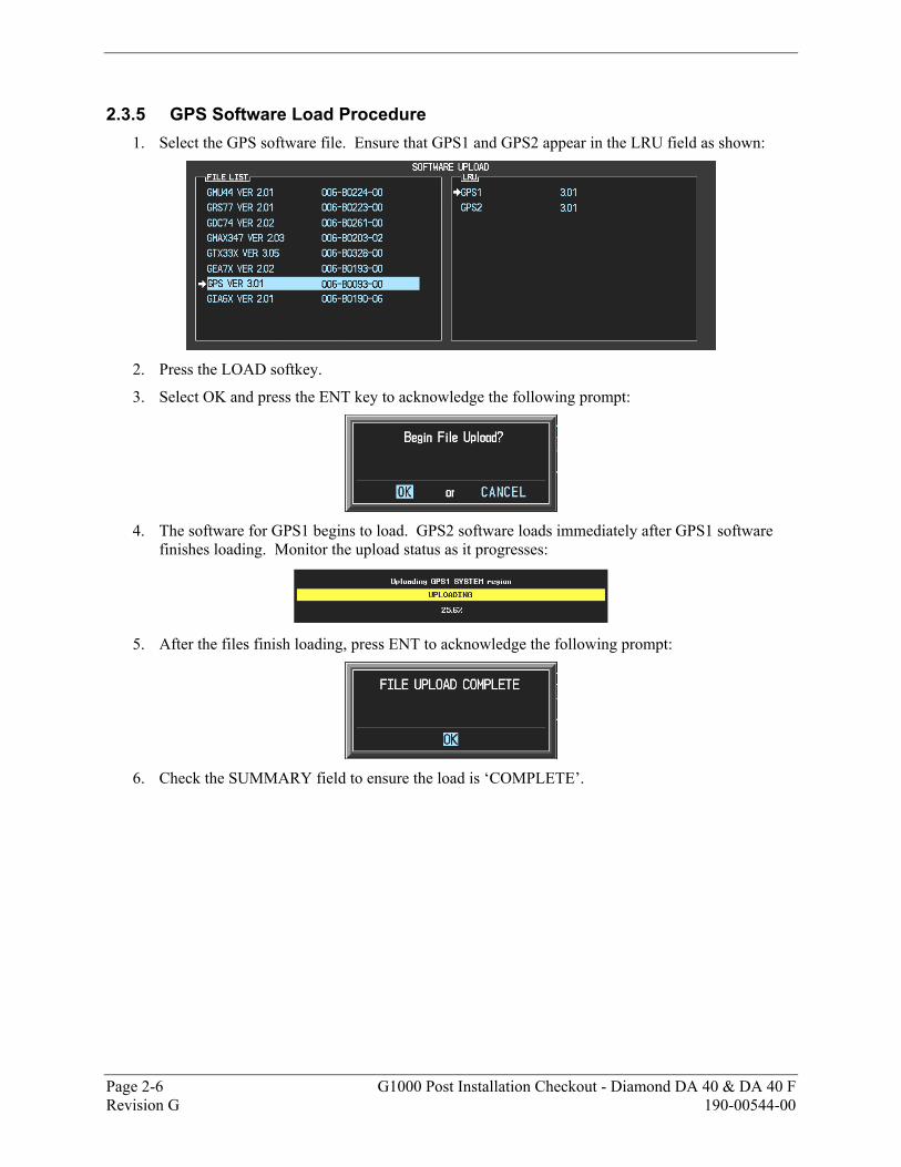
2.3.5 GPS Software Load Procedure 1. Select the GPS software file. Ensure that GPS1 and GPS2 appear in the LRU field as shown:
2. Press the LOAD softkey.
3. Select OK and press the ENT key to acknowledge the following prompt:
4. The software for GPS1 begins to load. GPS2 software loads immediately after GPS1 software
finishes loading. Monitor the upload status as it progresses:
5. After the files finish loading, press ENT to acknowledge the following prompt:
6. Check the SUMMARY field to ensure the load is ‘COMPLETE’.
G1000 Post Installation Checkout - Diamond DA 40 & DA 40 F Page 2-7 190-00544-00 Revision G
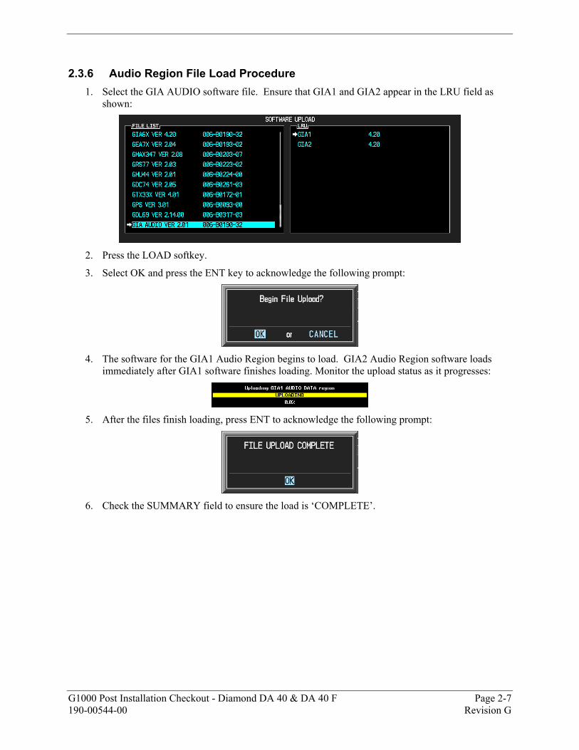
2.3.6 Audio Region File Load Procedure 1. Select the GIA AUDIO software file. Ensure that GIA1 and GIA2 appear in the LRU field as
shown:
2. Press the LOAD softkey.
3. Select OK and press the ENT key to acknowledge the following prompt:
4. The software for the GIA1 Audio Region begins to load. GIA2 Audio Region software loads
immediately after GIA1 software finishes loading. Monitor the upload status as it progresses:
5. After the files finish loading, press ENT to acknowledge the following prompt:
6. Check the SUMMARY field to ensure the load is ‘COMPLETE’.
Page 2-8 G1000 Post Installation Checkout - Diamond DA 40 & DA 40 F Revision G 190-00544-00
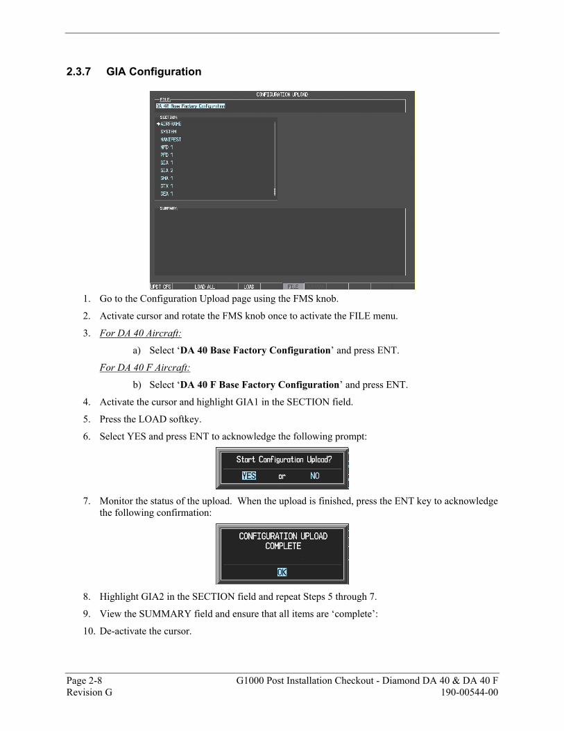
2.3.7 GIA Configuration
1. Go to the Configuration Upload page using the FMS knob.
2. Activate cursor and rotate the FMS knob once to activate the FILE menu.
3. For DA 40 Aircraft:
a) Select ‘DA 40 Base Factory Configuration’ and press ENT.
For DA 40 F Aircraft:
b) Select ‘DA 40 F Base Factory Configuration’ and press ENT.
4. Activate the cursor and highlight GIA1 in the SECTION field.
5. Press the LOAD softkey.
6. Select YES and press ENT to acknowledge the following prompt:
7. Monitor the status of the upload. When the upload is finished, press the ENT key to acknowledge
the following confirmation:
8. Highlight GIA2 in the SECTION field and repeat Steps 5 through 7.
9. View the SUMMARY field and ensure that all items are ‘complete’:
10. De-activate the cursor.
G1000 Post Installation Checkout - Diamond DA 40 & DA 40 F Page 2-9 190-00544-00 Revision G
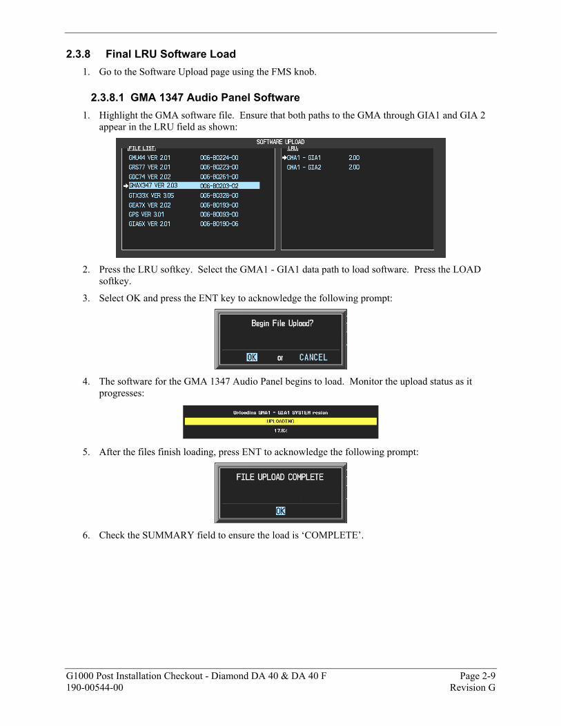
2.3.8 Final LRU Software Load 1. Go to the Software Upload page using the FMS knob.
2.3.8.1 GMA 1347 Audio Panel Software 1. Highlight the GMA software file. Ensure that both paths to the GMA through GIA1 and GIA 2
appear in the LRU field as shown:
2. Press the LRU softkey. Select the GMA1 - GIA1 data path to load software. Press the LOAD
softkey.
3. Select OK and press the ENT key to acknowledge the following prompt:
4. The software for the GMA 1347 Audio Panel begins to load. Monitor the upload status as it
progresses:
5. After the files finish loading, press ENT to acknowledge the following prompt:
6. Check the SUMMARY field to ensure the load is ‘COMPLETE’.
Page 2-10 G1000 Post Installation Checkout - Diamond DA 40 & DA 40 F Revision G 190-00544-00
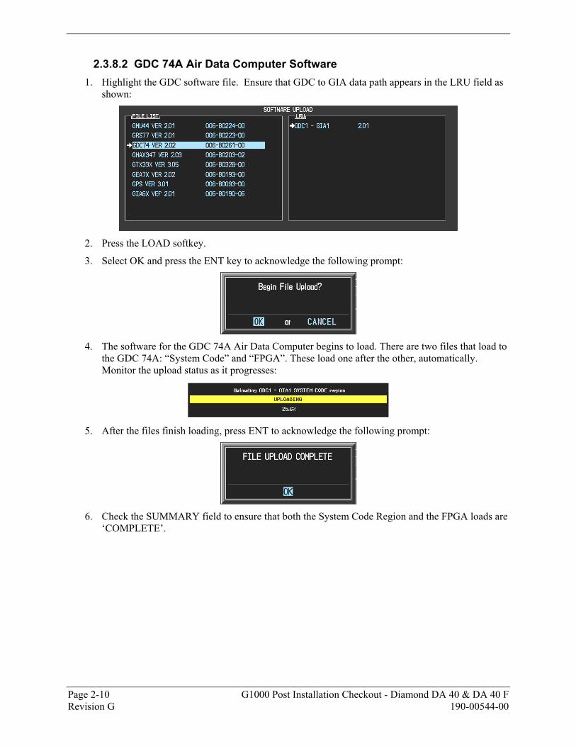
2.3.8.2 GDC 74A Air Data Computer Software 1. Highlight the GDC software file. Ensure that GDC to GIA data path appears in the LRU field as
shown:
2. Press the LOAD softkey.
3. Select OK and press the ENT key to acknowledge the following prompt:
4. The software for the GDC 74A Air Data Computer begins to load. There are two files that load to
the GDC 74A: “System Code” and “FPGA”. These load one after the other, automatically. Monitor the upload status as it progresses:
5. After the files finish loading, press ENT to acknowledge the following prompt:
6. Check the SUMMARY field to ensure that both the System Code Region and the FPGA loads are
‘COMPLETE’.
G1000 Post Installation Checkout - Diamond DA 40 & DA 40 F Page 2-11 190-00544-00 Revision G
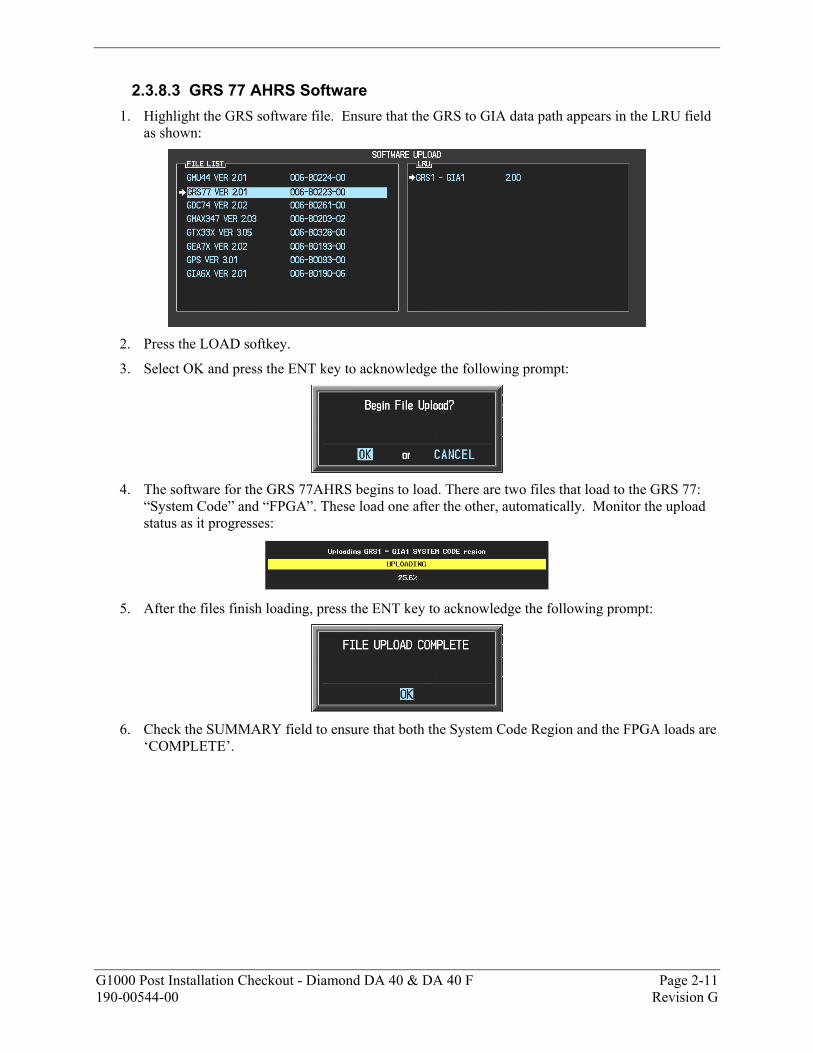
2.3.8.3 GRS 77 AHRS Software 1. Highlight the GRS software file. Ensure that the GRS to GIA data path appears in the LRU field
as shown:
2. Press the LOAD softkey.
3. Select OK and press the ENT key to acknowledge the following prompt:
4. The software for the GRS 77AHRS begins to load. There are two files that load to the GRS 77:
“System Code” and “FPGA”. These load one after the other, automatically. Monitor the upload status as it progresses:
5. After the files finish loading, press the ENT key to acknowledge the following prompt:
6. Check the SUMMARY field to ensure that both the System Code Region and the FPGA loads are
‘COMPLETE’.
Page 2-12 G1000 Post Installation Checkout - Diamond DA 40 & DA 40 F Revision G 190-00544-00
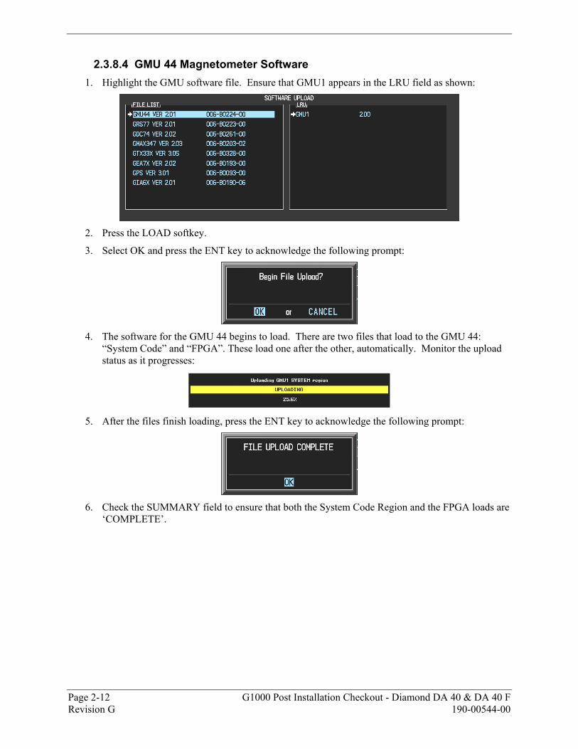
2.3.8.4 GMU 44 Magnetometer Software 1. Highlight the GMU software file. Ensure that GMU1 appears in the LRU field as shown:
2. Press the LOAD softkey.
3. Select OK and press the ENT key to acknowledge the following prompt:
4. The software for the GMU 44 begins to load. There are two files that load to the GMU 44:
“System Code” and “FPGA”. These load one after the other, automatically. Monitor the upload status as it progresses:
5. After the files finish loading, press the ENT key to acknowledge the following prompt:
6. Check the SUMMARY field to ensure that both the System Code Region and the FPGA loads are
‘COMPLETE’.
G1000 Post Installation Checkout - Diamond DA 40 & DA 40 F Page 2-13 190-00544-00 Revision G
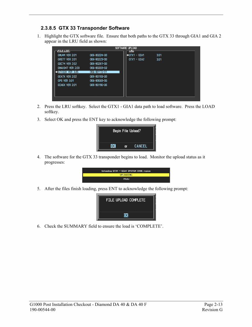
2.3.8.5 GTX 33 Transponder Software 1. Highlight the GTX software file. Ensure that both paths to the GTX 33 through GIA1 and GIA 2
appear in the LRU field as shown:
2. Press the LRU softkey. Select the GTX1 - GIA1 data path to load software. Press the LOAD
softkey.
3. Select OK and press the ENT key to acknowledge the following prompt:
4. The software for the GTX 33 transponder begins to load. Monitor the upload status as it
progresses:
5. After the files finish loading, press ENT to acknowledge the following prompt:
6. Check the SUMMARY field to ensure the load is ‘COMPLETE’.
Page 2-14 G1000 Post Installation Checkout - Diamond DA 40 & DA 40 F Revision G 190-00544-00
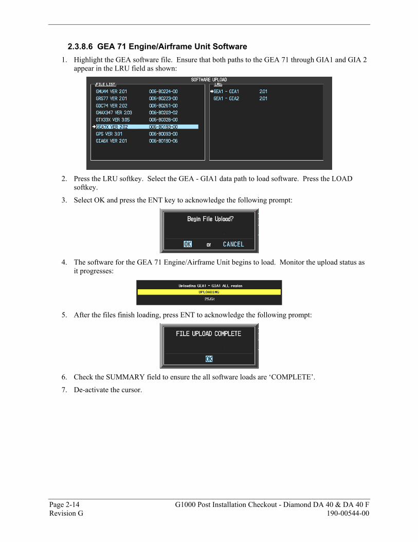
2.3.8.6 GEA 71 Engine/Airframe Unit Software 1. Highlight the GEA software file. Ensure that both paths to the GEA 71 through GIA1 and GIA 2
appear in the LRU field as shown:
2. Press the LRU softkey. Select the GEA - GIA1 data path to load software. Press the LOAD
softkey.
3. Select OK and press the ENT key to acknowledge the following prompt:
4. The software for the GEA 71 Engine/Airframe Unit begins to load. Monitor the upload status as
it progresses:
5. After the files finish loading, press ENT to acknowledge the following prompt:
6. Check the SUMMARY field to ensure the all software loads are ‘COMPLETE’.
7. De-activate the cursor.
G1000 Post Installation Checkout - Diamond DA 40 & DA 40 F Page 2-15 190-00544-00 Revision G
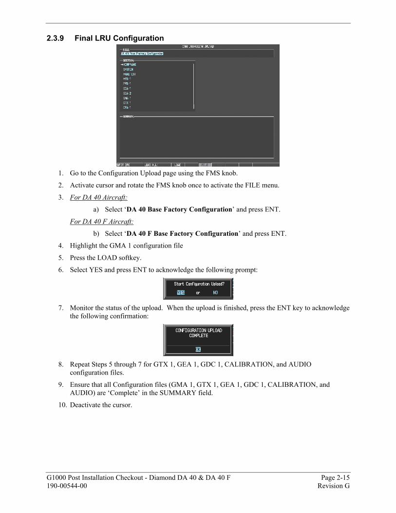
2.3.9 Final LRU Configuration
1. Go to the Configuration Upload page using the FMS knob.
2. Activate cursor and rotate the FMS knob once to activate the FILE menu.
3. For DA 40 Aircraft:
a) Select ‘DA 40 Base Factory Configuration’ and press ENT.
For DA 40 F Aircraft:
b) Select ‘DA 40 F Base Factory Configuration’ and press ENT.
4. Highlight the GMA 1 configuration file
5. Press the LOAD softkey.
6. Select YES and press ENT to acknowledge the following prompt:
7. Monitor the status of the upload. When the upload is finished, press the ENT key to acknowledge
the following confirmation:
8. Repeat Steps 5 through 7 for GTX 1, GEA 1, GDC 1, CALIBRATION, and AUDIO
configuration files.
9. Ensure that all Configuration files (GMA 1, GTX 1, GEA 1, GDC 1, CALIBRATION, and AUDIO) are ‘Complete’ in the SUMMARY field.
10. Deactivate the cursor.
Page 2-16 G1000 Post Installation Checkout - Diamond DA 40 & DA 40 F Revision G 190-00544-00
2.4 Final Configuration Items
2.4.1 Optional System Activation This section describes the steps that must be completed in order to configure the G1000 for optional systems. Only those systems that are installed must be configured.
IMPORTANT
If the configuration for an optional system is inadvertently loaded for a system that is NOT installed, the basic DA 40/DA 40F configuration for AIRFRAME, GIA 1, GIA 2 and the GMA must be reloaded. Following this, the configuration for the optional systems must be repeated.
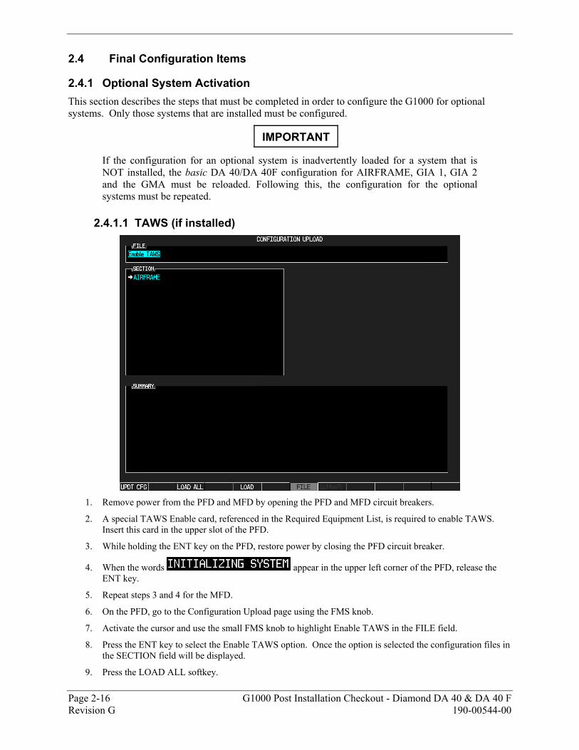
2.4.1.1 TAWS (if installed)
1. Remove power from the PFD and MFD by opening the PFD and MFD circuit breakers.
2. A special TAWS Enable card, referenced in the Required Equipment List, is required to enable TAWS. Insert this card in the upper slot of the PFD.
3. While holding the ENT key on the PFD, restore power by closing the PFD circuit breaker.
4. When the words appear in the upper left corner of the PFD, release the ENT key.
5. Repeat steps 3 and 4 for the MFD.
6. On the PFD, go to the Configuration Upload page using the FMS knob.
7. Activate the cursor and use the small FMS knob to highlight Enable TAWS in the FILE field.
8. Press the ENT key to select the Enable TAWS option. Once the option is selected the configuration files in the SECTION field will be displayed.
9. Press the LOAD ALL softkey.
G1000 Post Installation Checkout - Diamond DA 40 & DA 40 F Page 2-17 190-00544-00 Revision G
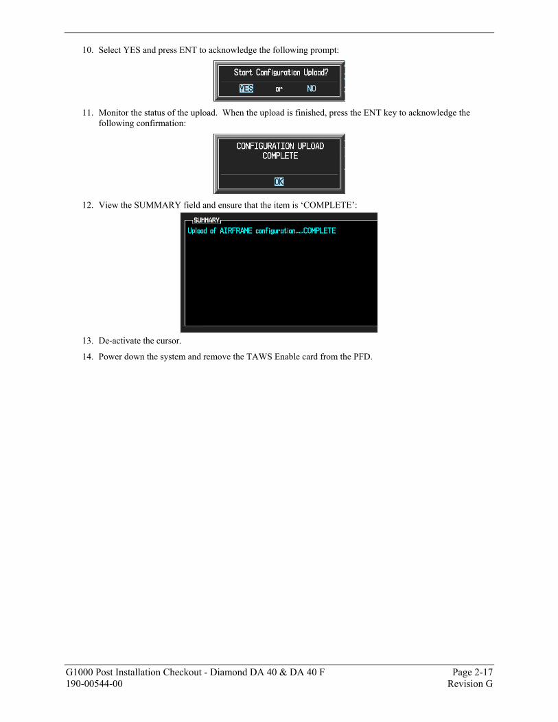
10. Select YES and press ENT to acknowledge the following prompt:
11. Monitor the status of the upload. When the upload is finished, press the ENT key to acknowledge the
following confirmation:
12. View the SUMMARY field and ensure that the item is ‘COMPLETE’:
13. De-activate the cursor.
14. Power down the system and remove the TAWS Enable card from the PFD.
Page 2-18 G1000 Post Installation Checkout - Diamond DA 40 & DA 40 F Revision G 190-00544-00
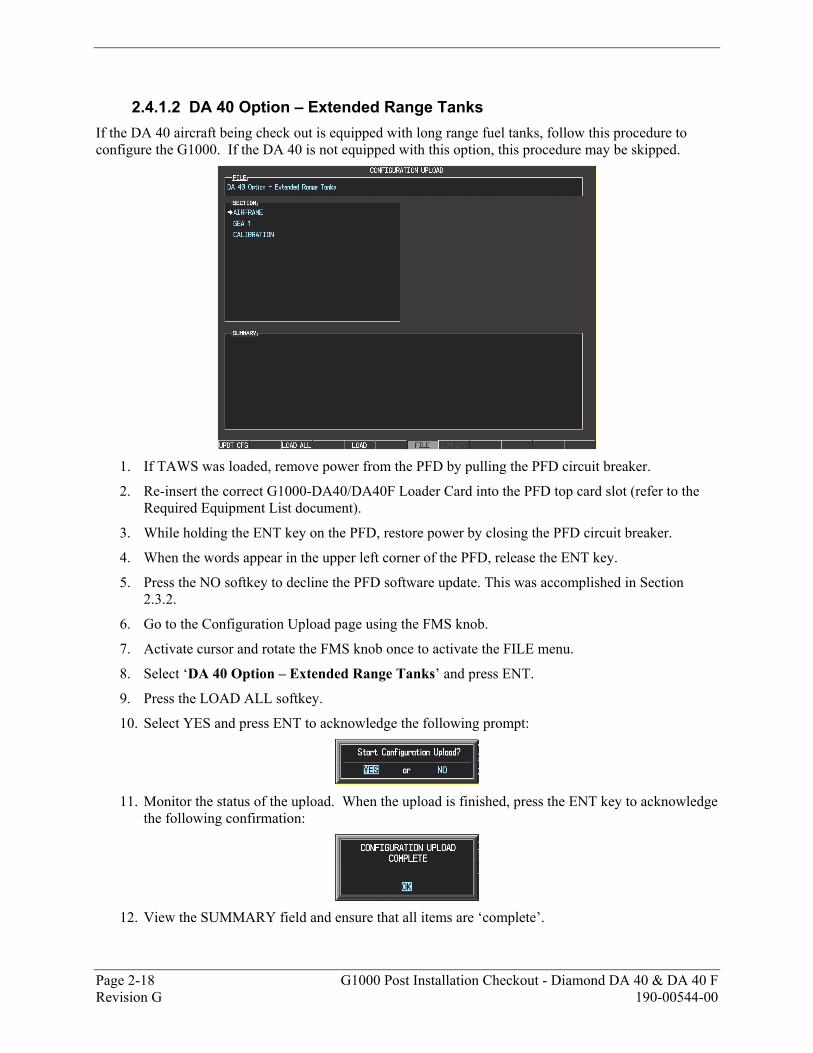
2.4.1.2 DA 40 Option – Extended Range Tanks If the DA 40 aircraft being check out is equipped with long range fuel tanks, follow this procedure to configure the G1000. If the DA 40 is not equipped with this option, this procedure may be skipped.
1. If TAWS was loaded, remove power from the PFD by pulling the PFD circuit breaker.
2. Re-insert the correct G1000-DA40/DA40F Loader Card into the PFD top card slot (refer to the Required Equipment List document).
3. While holding the ENT key on the PFD, restore power by closing the PFD circuit breaker.
4. When the words appear in the upper left corner of the PFD, release the ENT key.
5. Press the NO softkey to decline the PFD software update. This was accomplished in Section 2.3.2.
6. Go to the Configuration Upload page using the FMS knob.
7. Activate cursor and rotate the FMS knob once to activate the FILE menu.
8. Select ‘DA 40 Option – Extended Range Tanks’ and press ENT.
9. Press the LOAD ALL softkey.
10. Select YES and press ENT to acknowledge the following prompt:
11. Monitor the status of the upload. When the upload is finished, press the ENT key to acknowledge
the following confirmation:
12. View the SUMMARY field and ensure that all items are ‘complete’.
G1000 Post Installation Checkout - Diamond DA 40 & DA 40 F Page 2-19 190-00544-00 Revision G
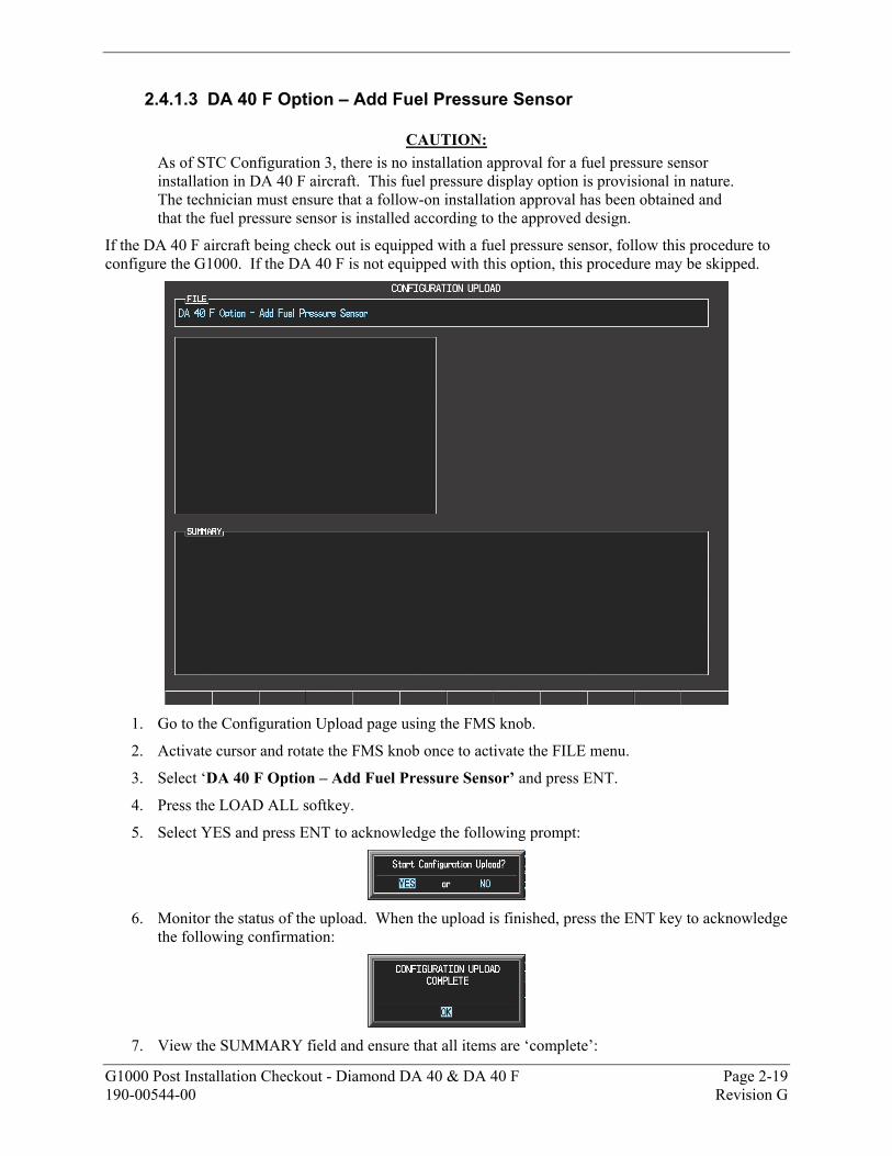
2.4.1.3 DA 40 F Option – Add Fuel Pressure Sensor
CAUTION: As of STC Configuration 3, there is no installation approval for a fuel pressure sensor installation in DA 40 F aircraft. This fuel pressure display option is provisional in nature. The technician must ensure that a follow-on installation approval has been obtained and that the fuel pressure sensor is installed according to the approved design.
If the DA 40 F aircraft being check out is equipped with a fuel pressure sensor, follow this procedure to configure the G1000. If the DA 40 F is not equipped with this option, this procedure may be skipped.
1. Go to the Configuration Upload page using the FMS knob.
2. Activate cursor and rotate the FMS knob once to activate the FILE menu.
3. Select ‘DA 40 F Option – Add Fuel Pressure Sensor’ and press ENT.
4. Press the LOAD ALL softkey.
5. Select YES and press ENT to acknowledge the following prompt:
6. Monitor the status of the upload. When the upload is finished, press the ENT key to acknowledge
the following confirmation:
7. View the SUMMARY field and ensure that all items are ‘complete’:
Page 2-20 G1000 Post Installation Checkout - Diamond DA 40 & DA 40 F Revision G 190-00544-00
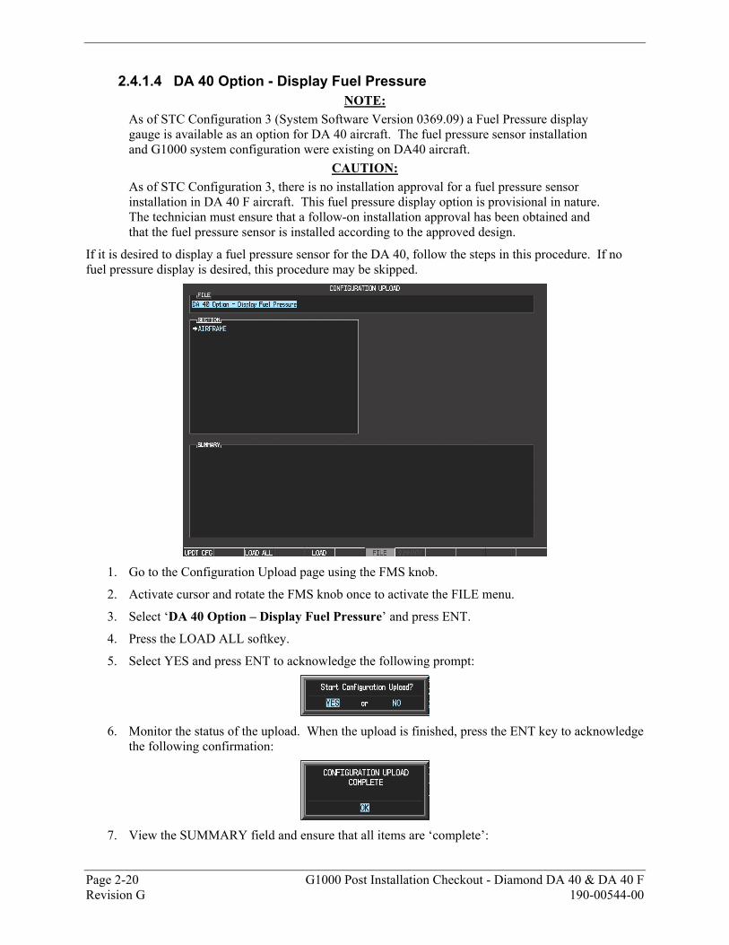
2.4.1.4 DA 40 Option - Display Fuel Pressure NOTE:
As of STC Configuration 3 (System Software Version 0369.09) a Fuel Pressure display gauge is available as an option for DA 40 aircraft. The fuel pressure sensor installation and G1000 system configuration were existing on DA40 aircraft.
CAUTION: As of STC Configuration 3, there is no installation approval for a fuel pressure sensor installation in DA 40 F aircraft. This fuel pressure display option is provisional in nature. The technician must ensure that a follow-on installation approval has been obtained and that the fuel pressure sensor is installed according to the approved design.
If it is desired to display a fuel pressure sensor for the DA 40, follow the steps in this procedure. If no fuel pressure display is desired, this procedure may be skipped.
1. Go to the Configuration Upload page using the FMS knob.
2. Activate cursor and rotate the FMS knob once to activate the FILE menu.
3. Select ‘DA 40 Option – Display Fuel Pressure’ and press ENT.
4. Press the LOAD ALL softkey.
5. Select YES and press ENT to acknowledge the following prompt:
6. Monitor the status of the upload. When the upload is finished, press the ENT key to acknowledge
the following confirmation:
7. View the SUMMARY field and ensure that all items are ‘complete’:
G1000 Post Installation Checkout - Diamond DA 40 & DA 40 F Page 2-21 190-00544-00 Revision G
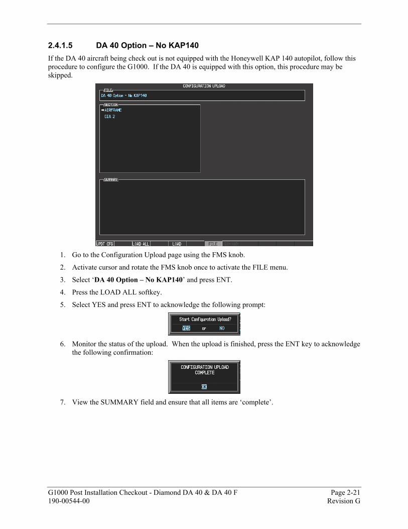
2.4.1.5 DA 40 Option – No KAP140 If the DA 40 aircraft being check out is not equipped with the Honeywell KAP 140 autopilot, follow this procedure to configure the G1000. If the DA 40 is equipped with this option, this procedure may be skipped.
1. Go to the Configuration Upload page using the FMS knob.
2. Activate cursor and rotate the FMS knob once to activate the FILE menu.
3. Select ‘DA 40 Option – No KAP140’ and press ENT.
4. Press the LOAD ALL softkey.
5. Select YES and press ENT to acknowledge the following prompt:
6. Monitor the status of the upload. When the upload is finished, press the ENT key to acknowledge
the following confirmation:
7. View the SUMMARY field and ensure that all items are ‘complete’.
Page 2-22 G1000 Post Installation Checkout - Diamond DA 40 & DA 40 F Revision G 190-00544-00
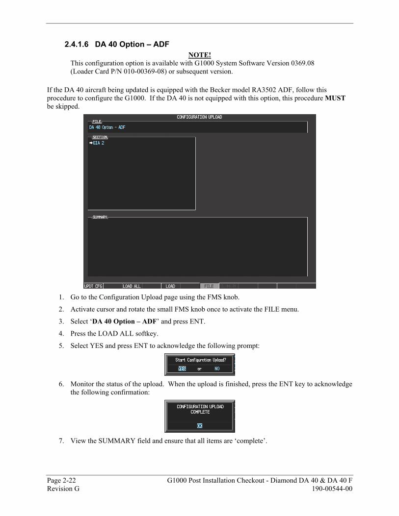
2.4.1.6 DA 40 Option – ADF NOTE!
This configuration option is available with G1000 System Software Version 0369.08 (Loader Card P/N 010-00369-08) or subsequent version.
If the DA 40 aircraft being updated is equipped with the Becker model RA3502 ADF, follow this procedure to configure the G1000. If the DA 40 is not equipped with this option, this procedure MUST be skipped.
1. Go to the Configuration Upload page using the FMS knob.
2. Activate cursor and rotate the small FMS knob once to activate the FILE menu.
3. Select ‘DA 40 Option – ADF’ and press ENT.
4. Press the LOAD ALL softkey.
5. Select YES and press ENT to acknowledge the following prompt:
6. Monitor the status of the upload. When the upload is finished, press the ENT key to acknowledge
the following confirmation:
7. View the SUMMARY field and ensure that all items are ‘complete’.
G1000 Post Installation Checkout - Diamond DA 40 & DA 40 F Page 2-23 190-00544-00 Revision G
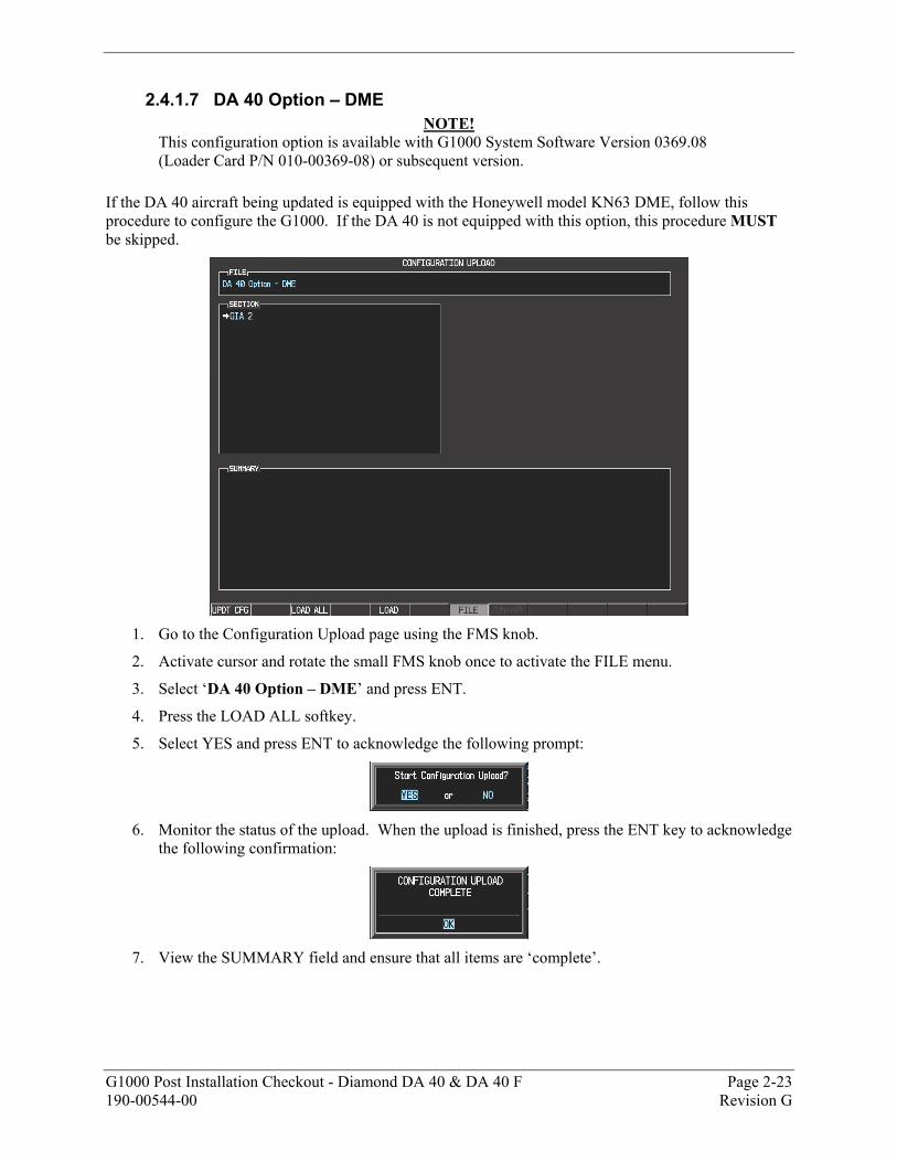
2.4.1.7 DA 40 Option – DME NOTE!
This configuration option is available with G1000 System Software Version 0369.08 (Loader Card P/N 010-00369-08) or subsequent version.
If the DA 40 aircraft being updated is equipped with the Honeywell model KN63 DME, follow this procedure to configure the G1000. If the DA 40 is not equipped with this option, this procedure MUST be skipped.
1. Go to the Configuration Upload page using the FMS knob.
2. Activate cursor and rotate the small FMS knob once to activate the FILE menu.
3. Select ‘DA 40 Option – DME’ and press ENT.
4. Press the LOAD ALL softkey.
5. Select YES and press ENT to acknowledge the following prompt:
6. Monitor the status of the upload. When the upload is finished, press the ENT key to acknowledge
the following confirmation:
7. View the SUMMARY field and ensure that all items are ‘complete’.
Page 2-24 G1000 Post Installation Checkout - Diamond DA 40 & DA 40 F Revision G 190-00544-00
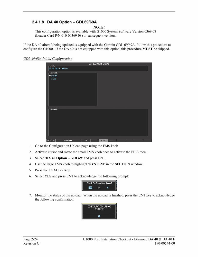
2.4.1.8 DA 40 Option – GDL69/69A NOTE!
This configuration option is available with G1000 System Software Version 0369.08 (Loader Card P/N 010-00369-08) or subsequent version.
If the DA 40 aircraft being updated is equipped with the Garmin GDL 69/69A, follow this procedure to configure the G1000. If the DA 40 is not equipped with this option, this procedure MUST be skipped. GDL 69/69A Initial Configuration
1. Go to the Configuration Upload page using the FMS knob.
2. Activate cursor and rotate the small FMS knob once to activate the FILE menu.
3. Select ‘DA 40 Option – GDL69’ and press ENT.
4. Use the large FMS knob to highlight ‘SYSTEM’ in the SECTION window.
5. Press the LOAD softkey.
6. Select YES and press ENT to acknowledge the following prompt:
7. Monitor the status of the upload. When the upload is finished, press the ENT key to acknowledge
the following confirmation:
G1000 Post Installation Checkout - Diamond DA 40 & DA 40 F Page 2-25 190-00544-00 Revision G
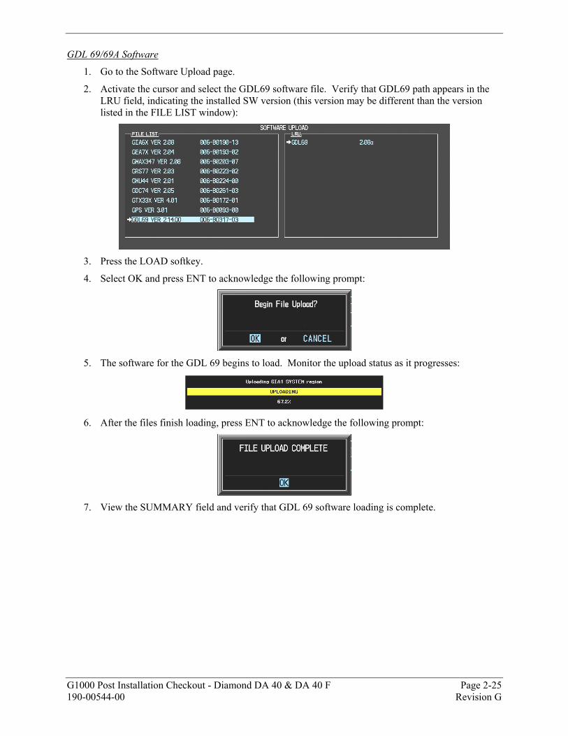
GDL 69/69A Software
1. Go to the Software Upload page.
2. Activate the cursor and select the GDL69 software file. Verify that GDL69 path appears in the LRU field, indicating the installed SW version (this version may be different than the version listed in the FILE LIST window):
3. Press the LOAD softkey.
4. Select OK and press ENT to acknowledge the following prompt:
5. The software for the GDL 69 begins to load. Monitor the upload status as it progresses:
6. After the files finish loading, press ENT to acknowledge the following prompt:
7. View the SUMMARY field and verify that GDL 69 software loading is complete.
Page 2-26 G1000 Post Installation Checkout - Diamond DA 40 & DA 40 F Revision G 190-00544-00
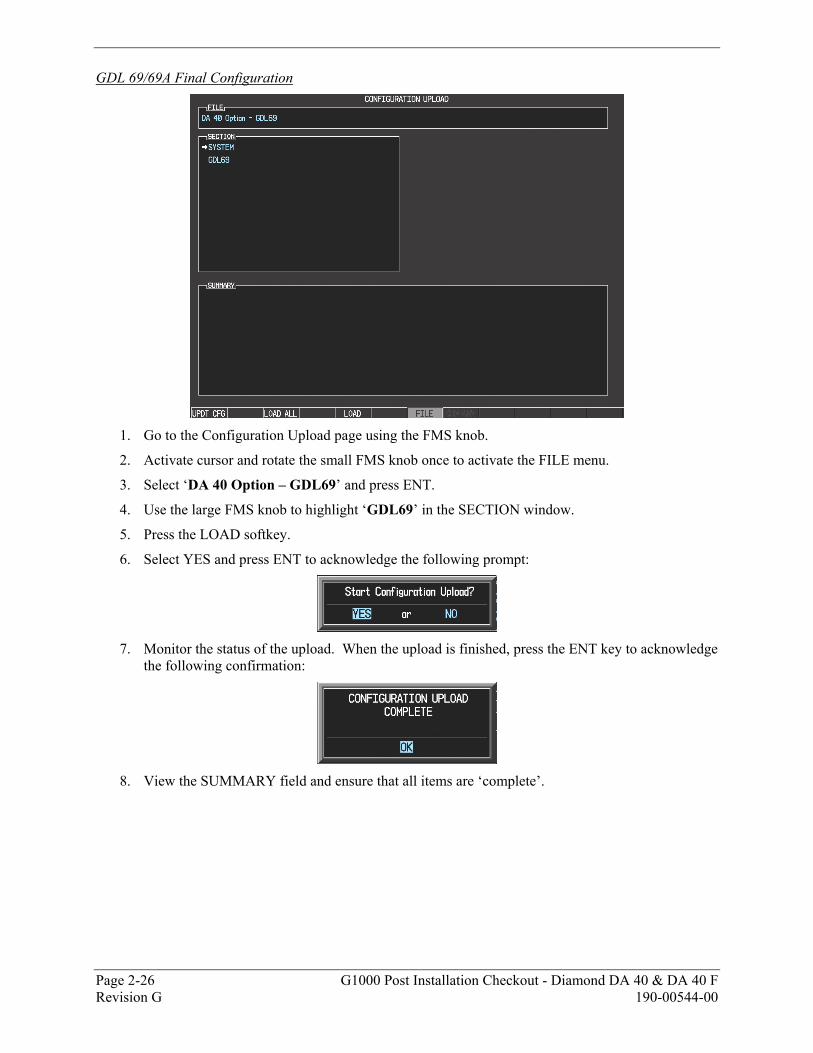
GDL 69/69A Final Configuration
1. Go to the Configuration Upload page using the FMS knob.
2. Activate cursor and rotate the small FMS knob once to activate the FILE menu.
3. Select ‘DA 40 Option – GDL69’ and press ENT.
4. Use the large FMS knob to highlight ‘GDL69’ in the SECTION window.
5. Press the LOAD softkey.
6. Select YES and press ENT to acknowledge the following prompt:
7. Monitor the status of the upload. When the upload is finished, press the ENT key to acknowledge
the following confirmation:
8. View the SUMMARY field and ensure that all items are ‘complete’.
G1000 Post Installation Checkout - Diamond DA 40 & DA 40 F Page 2-27 190-00544-00 Revision G
2.4.1.9 Display Lighting Set-Up
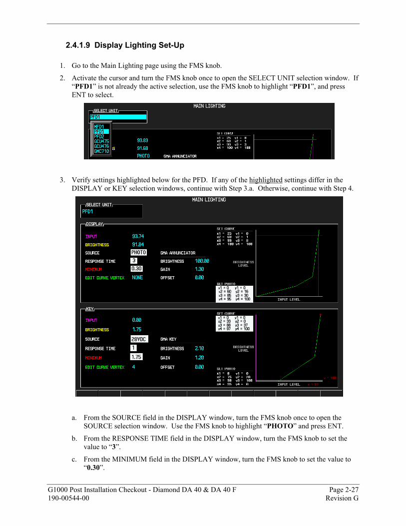
1. Go to the Main Lighting page using the FMS knob.
2. Activate the cursor and turn the FMS knob once to open the SELECT UNIT selection window. If “PFD1” is not already the active selection, use the FMS knob to highlight “PFD1”, and press ENT to select.
3. Verify settings highlighted below for the PFD. If any of the highlighted settings differ in the DISPLAY or KEY selection windows, continue with Step 3.a. Otherwise, continue with Step 4.
a. From the SOURCE field in the DISPLAY window, turn the FMS knob once to open the SOURCE selection window. Use the FMS knob to highlight “PHOTO” and press ENT.
b. From the RESPONSE TIME field in the DISPLAY window, turn the FMS knob to set the value to “3”.
c. From the MINIMUM field in the DISPLAY window, turn the FMS knob to set the value to “0.30”.
Page 2-28 G1000 Post Installation Checkout - Diamond DA 40 & DA 40 F Revision G 190-00544-00
d. From the EDIT CURVE VERTEX field in the DISPLAY window, turn the FMS knob once to open the EDIT CURVE VERTEX selection window. Use the FMS knob to highlight “1” and press ENT. Then, use the RANGE/PAN control on the PFD to set x1 and y1 coordinates as shown under SET PHOTO in the DISPLAY window, where x1 = 0 and y1 = 0.
Move the RANGE/PAN control left and right to adjust the x-coordinate or up and down to adjust the y-coordinate.
e. Repeat this step for EDIT CURVE VERTEX “2” (x2 = 60, y2 = 16), “3” (x3 = 85, y3 = 30), and “4” (x4 = 95, y4 = 100) to achieve the values shown in the above figure under SET PHOTO in the DISPLAY window.
It may not be possible to adjust the x and y coordinates of each curve vertex sequentially to the full setting shown at times without first adjusting some of the other variables. For instance, if x2 cannot be set to the specified value, adjust as high as possible and continue through the process. After editing curve vertex 3 and 4, return to edit curve vertex 2 and increase x2 to the specified value.
f. From the SOURCE field in the KEY window, turn the FMS knob once to open the SOURCE selection window. Use the FMS knob to highlight “28VDC” and press ENT.
g. From the RESPONSE TIME field in the KEY window, turn the FMS knob to set the value to “1”.
h. From the MINIMUM field in the KEY window, turn the FMS knob to set the value to “1.75”.
i. From the EDIT CURVE VERTEX field in the KEY window, turn the FMS knob once to open the EDIT CURVE VERTEX selection window. Use the FMS knob to highlight “1” and press ENT. Then, use the RANGE/PAN control on the PFD to set x1 and y1 coordinates as shown under SET CURVE in the KEY window, where x1 = 0 and y1 = 0.
Move the RANGE/PAN control left and right to adjust the x-coordinate or up and down to adjust the y-coordinate.
j. Repeat this step for EDIT CURVE VERTEX “2” (x2 = 33, y2 = 0), “3” (x3 = 88, y3 = 37), and “4” (x4 = 97, y4 = 100) to achieve the values shown in the above figure under SET CURVE in the KEY window.
It may not be possible to adjust the x and y coordinates of each curve vertex sequentially to the full setting shown at times without first adjusting some of the other variables. For instance, if x2 cannot be set to the specified value, adjust as high as possible and continue through the process. After editing curve vertex 3 and 4, return to edit curve vertex 2 and increase x2 to the specified value.
NOTE
NOTE
NOTE
NOTE
G1000 Post Installation Checkout - Diamond DA 40 & DA 40 F Page 2-29 190-00544-00 Revision G
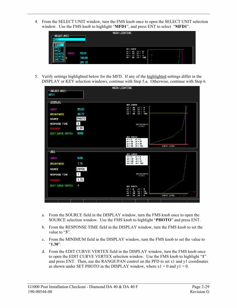
4. From the SELECT UNIT window, turn the FMS knob once to open the SELECT UNIT selection window. Use the FMS knob to highlight “MFD1”, and press ENT to select “MFD1”.
5. Verify settings highlighted below for the MFD. If any of the highlighted settings differ in the DISPLAY or KEY selection windows, continue with Step 5.a. Otherwise, continue with Step 6.
a. From the SOURCE field in the DISPLAY window, turn the FMS knob once to open the SOURCE selection window. Use the FMS knob to highlight “PHOTO” and press ENT.
b. From the RESPONSE TIME field in the DISPLAY window, turn the FMS knob to set the value to “3”.
c. From the MINIMUM field in the DISPLAY window, turn the FMS knob to set the value to “1.30”.
d. From the EDIT CURVE VERTEX field in the DISPLAY window, turn the FMS knob once to open the EDIT CURVE VERTEX selection window. Use the FMS knob to highlight “1” and press ENT. Then, use the RANGE/PAN control on the PFD to set x1 and y1 coordinates as shown under SET PHOTO in the DISPLAY window, where x1 = 0 and y1 = 0.
Page 2-30 G1000 Post Installation Checkout - Diamond DA 40 & DA 40 F Revision G 190-00544-00
Move the RANGE/PAN control left and right to adjust the x-coordinate or up and down to adjust the y-coordinate.
e. Repeat this step for EDIT CURVE VERTEX “2” (x2 = 60, y2 = 20), “3” (x3 = 85, y3 = 40), and “4” (x4 = 98, y4 = 100) to achieve the values shown in the above figure under SET PHOTO in the DISPLAY window.
It may not be possible to adjust the x and y coordinates of each curve vertex sequentially to the full setting shown at times without first adjusting some of the other variables. For instance, if x2 cannot be set to the specified value, adjust as high as possible and continue through the process. After editing curve vertex 3 and 4, return to edit curve vertex 2 and increase x2 to the specified value.
f. From the SOURCE field in the KEY window, turn the FMS knob once to open the SOURCE selection window. Use the FMS knob to highlight “28VDC” and press ENT.
g. From the RESPONSE TIME field in the KEY window, turn the FMS knob to set the value to “1”.
h. From the MINIMUM field in the KEY window, turn the FMS knob to set the value to “1.75”.
i. From the EDIT CURVE VERTEX field in the KEY window, turn the FMS knob once to open the EDIT CURVE VERTEX selection window. Use the FMS knob to highlight “1” and press ENT. Then, use the RANGE/PAN control on the PFD to set x1 and y1 coordinates as shown under SET CURVE in the KEY window, where x1 = 0 and y1 = 0.
Move the RANGE/PAN control left and right to adjust the x-coordinate or up and down to adjust the y-coordinate.
j. Repeat this step for EDIT CURVE VERTEX “2” (x2 = 33, y2 = 0), “3” (x3 = 88, y3 = 37), and “4” (x4 = 97, y4 = 100) to achieve the values shown in the above figure under SET CURVE in the KEY window.
It may not be possible to adjust the x and y coordinates of each curve vertex sequentially to the full setting shown at times without first adjusting some of the other variables. For instance, if x2 cannot be set to the specified value, adjust as high as possible and continue through the process. After editing curve vertex 3 and 4, return to edit curve vertex 2 and increase x2 to the specified value.
6. Press the FMS knob to deactivate the cursor.
NOTE
NOTE
NOTE
NOTE
G1000 Post Installation Checkout - Diamond DA 40 & DA 40 F Page 2-31 190-00544-00 Revision G
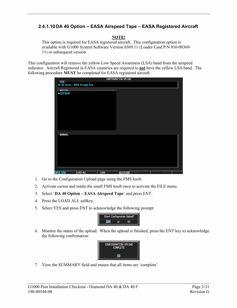
2.4.1.10 DA 40 Option – EASA Airspeed Tape – EASA Registered Aircraft
NOTE! This option is required for EASA registered aircraft. This configuration option is available with G1000 System Software Version 0369.11 (Loader Card P/N 010-00369-11) or subsequent version.
This configuration will remove the yellow Low Speed Awareness (LSA) band from the airspeed indicator. Aircraft Registered in EASA countries are required to not have the yellow LSA band. The following procedure MUST be completed for EASA registered aircraft.
1. Go to the Configuration Upload page using the FMS knob.
2. Activate cursor and rotate the small FMS knob once to activate the FILE menu.
3. Select ‘DA 40 Option – EASA Airspeed Tape’ and press ENT.
4. Press the LOAD ALL softkey.
5. Select YES and press ENT to acknowledge the following prompt:
6. Monitor the status of the upload. When the upload is finished, press the ENT key to acknowledge
the following confirmation:
7. View the SUMMARY field and ensure that all items are ‘complete’.

Page 2-32 G1000 Post Installation Checkout - Diamond DA 40 & DA 40 F Revision G 190-00544-00
2.4.1.11 DA 40 Option – GFC 700 AFCS If GFC 700 AFCS is installed, refer to G1000/GFC700 Post Installation Checkout – Diamond DA 40, GARMIN P/N 190-00492-02.
G1000 Post Installation Checkout - Diamond DA 40 & DA 40 F Page 2-33 190-00544-00 Revision G
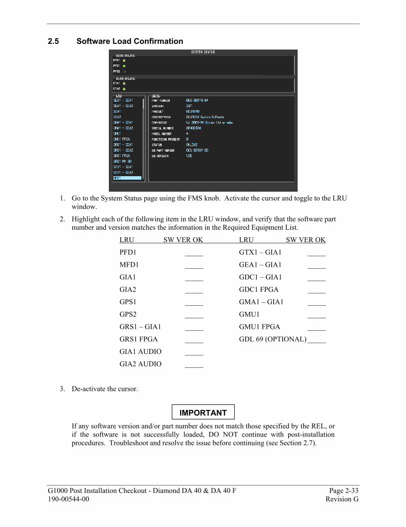
2.5 Software Load Confirmation
1. Go to the System Status page using the FMS knob. Activate the cursor and toggle to the LRU
window.
2. Highlight each of the following item in the LRU window, and verify that the software part number and version matches the information in the Required Equipment List.
LRU SW VER OK LRU SW VER OK
PFD1 _____ GTX1 – GIA1 _____
MFD1 _____ GEA1 – GIA1 _____
GIA1 _____ GDC1 – GIA1 _____
GIA2 _____ GDC1 FPGA _____
GPS1 _____ GMA1 – GIA1 _____
GPS2 _____ GMU1 _____
GRS1 – GIA1 _____ GMU1 FPGA _____
GRS1 FPGA _____ GDL 69 (OPTIONAL) _____
GIA1 AUDIO _____
GIA2 AUDIO _____
3. De-activate the cursor.
If any software version and/or part number does not match those specified by the REL, or if the software is not successfully loaded, DO NOT continue with post-installation procedures. Troubleshoot and resolve the issue before continuing (see Section 2.7).
IMPORTANT
Page 2-34 G1000 Post Installation Checkout - Diamond DA 40 & DA 40 F Revision G 190-00544-00
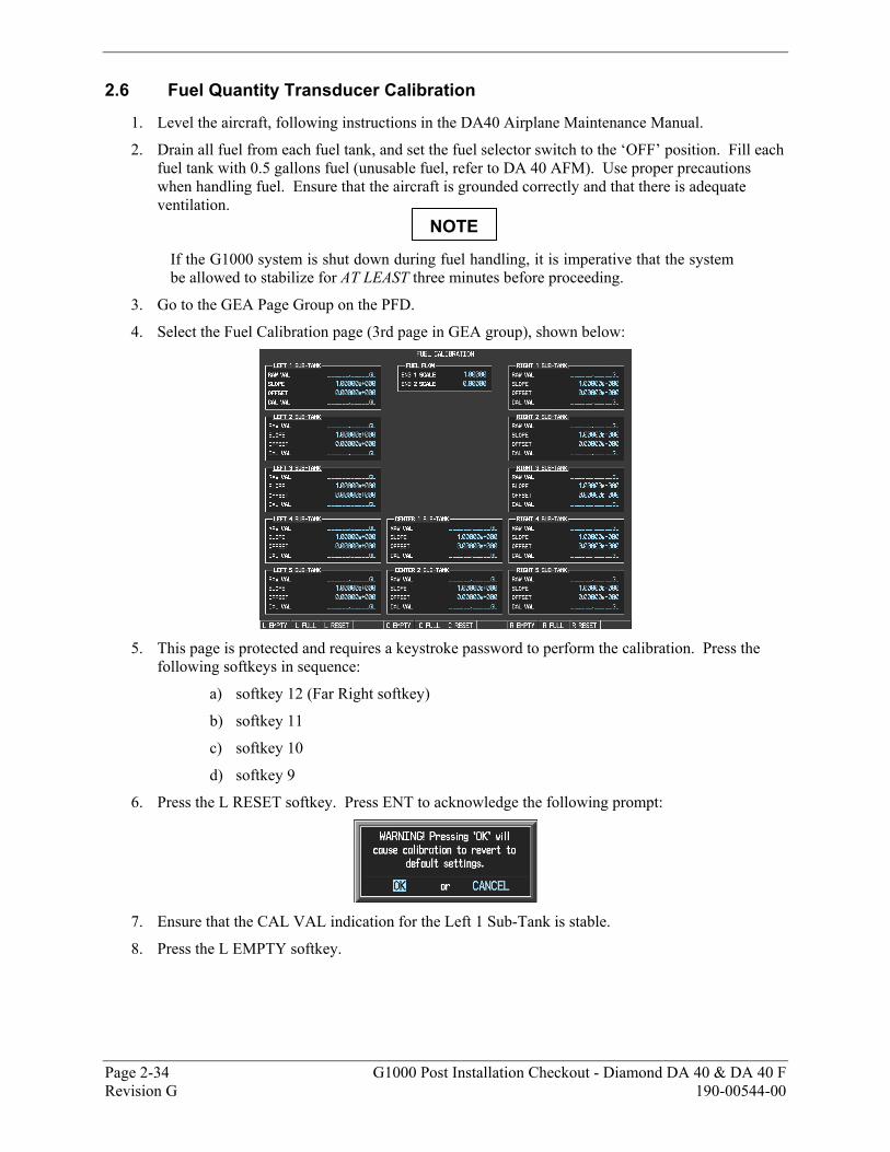
2.6 Fuel Quantity Transducer Calibration
1. Level the aircraft, following instructions in the DA40 Airplane Maintenance Manual.
2. Drain all fuel from each fuel tank, and set the fuel selector switch to the ‘OFF’ position. Fill each fuel tank with 0.5 gallons fuel (unusable fuel, refer to DA 40 AFM). Use proper precautions when handling fuel. Ensure that the aircraft is grounded correctly and that there is adequate ventilation.
If the G1000 system is shut down during fuel handling, it is imperative that the system be allowed to stabilize for AT LEAST three minutes before proceeding.
3. Go to the GEA Page Group on the PFD.
4. Select the Fuel Calibration page (3rd page in GEA group), shown below:
5. This page is protected and requires a keystroke password to perform the calibration. Press the
following softkeys in sequence:
a) softkey 12 (Far Right softkey)
b) softkey 11
c) softkey 10
d) softkey 9
6. Press the L RESET softkey. Press ENT to acknowledge the following prompt:
7. Ensure that the CAL VAL indication for the Left 1 Sub-Tank is stable.
8. Press the L EMPTY softkey.
NOTE
G1000 Post Installation Checkout - Diamond DA 40 & DA 40 F Page 2-35 190-00544-00 Revision G
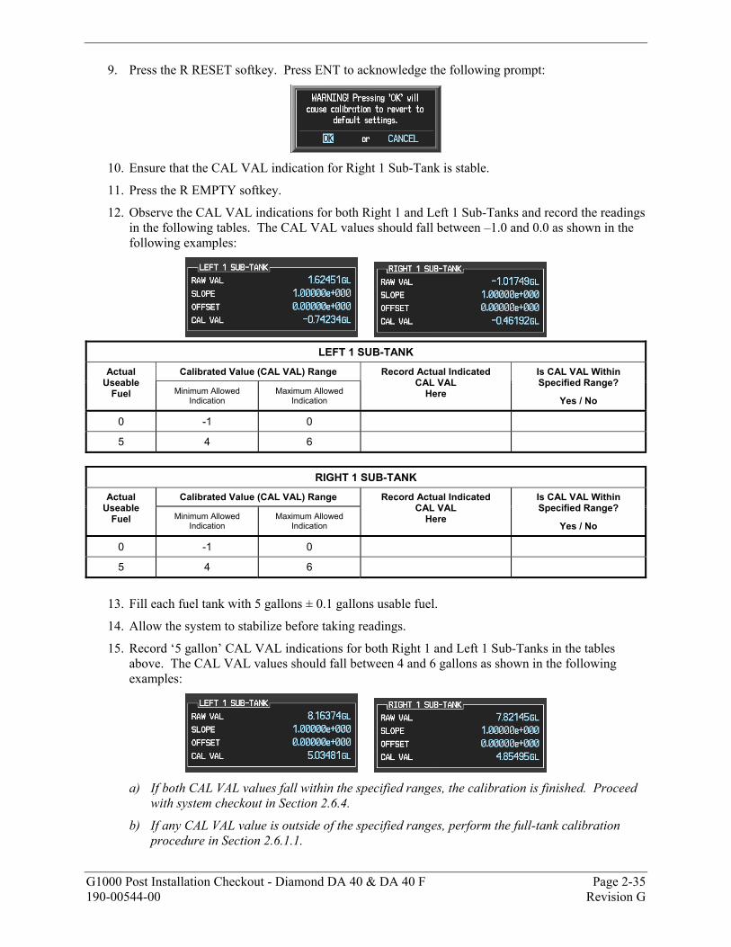
9. Press the R RESET softkey. Press ENT to acknowledge the following prompt:
10. Ensure that the CAL VAL indication for Right 1 Sub-Tank is stable.
11. Press the R EMPTY softkey.
12. Observe the CAL VAL indications for both Right 1 and Left 1 Sub-Tanks and record the readings in the following tables. The CAL VAL values should fall between –1.0 and 0.0 as shown in the following examples:
LEFT 1 SUB-TANK
Calibrated Value (CAL VAL) Range Actual Useable
Fuel Minimum Allowed Indication
Maximum Allowed Indication
Record Actual Indicated CAL VAL
Here
Is CAL VAL Within Specified Range?
Yes / No
0 -1 0
5 4 6
RIGHT 1 SUB-TANK
Calibrated Value (CAL VAL) Range Actual Useable
Fuel Minimum Allowed Indication
Maximum Allowed Indication
Record Actual Indicated CAL VAL
Here
Is CAL VAL Within Specified Range?
Yes / No
0 -1 0
5 4 6
13. Fill each fuel tank with 5 gallons ± 0.1 gallons usable fuel.
14. Allow the system to stabilize before taking readings.
15. Record ‘5 gallon’ CAL VAL indications for both Right 1 and Left 1 Sub-Tanks in the tables above. The CAL VAL values should fall between 4 and 6 gallons as shown in the following examples:
a) If both CAL VAL values fall within the specified ranges, the calibration is finished. Proceed
with system checkout in Section 2.6.4.
b) If any CAL VAL value is outside of the specified ranges, perform the full-tank calibration procedure in Section 2.6.1.1.
Page 2-36 G1000 Post Installation Checkout - Diamond DA 40 & DA 40 F Revision G 190-00544-00
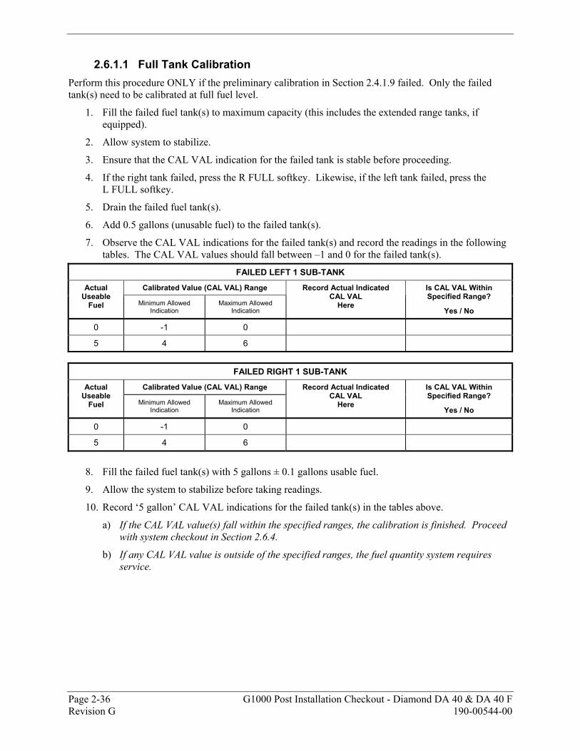
2.6.1.1 Full Tank Calibration Perform this procedure ONLY if the preliminary calibration in Section 2.4.1.9 failed. Only the failed tank(s) need to be calibrated at full fuel level.
1. Fill the failed fuel tank(s) to maximum capacity (this includes the extended range tanks, if equipped).
2. Allow system to stabilize.
3. Ensure that the CAL VAL indication for the failed tank is stable before proceeding.
4. If the right tank failed, press the R FULL softkey. Likewise, if the left tank failed, press the L FULL softkey.
5. Drain the failed fuel tank(s).
6. Add 0.5 gallons (unusable fuel) to the failed tank(s).
7. Observe the CAL VAL indications for the failed tank(s) and record the readings in the following tables. The CAL VAL values should fall between –1 and 0 for the failed tank(s).
FAILED LEFT 1 SUB-TANK
Calibrated Value (CAL VAL) Range Actual Useable
Fuel Minimum Allowed Indication
Maximum Allowed Indication
Record Actual Indicated CAL VAL
Here
Is CAL VAL Within Specified Range?
Yes / No
0 -1 0
5 4 6
FAILED RIGHT 1 SUB-TANK
Calibrated Value (CAL VAL) Range Actual Useable
Fuel Minimum Allowed Indication
Maximum Allowed Indication
Record Actual Indicated CAL VAL
Here
Is CAL VAL Within Specified Range?
Yes / No
0 -1 0
5 4 6
8. Fill the failed fuel tank(s) with 5 gallons ± 0.1 gallons usable fuel.
9. Allow the system to stabilize before taking readings.
10. Record ‘5 gallon’ CAL VAL indications for the failed tank(s) in the tables above.
a) If the CAL VAL value(s) fall within the specified ranges, the calibration is finished. Proceed with system checkout in Section 2.6.4.
b) If any CAL VAL value is outside of the specified ranges, the fuel quantity system requires service.
G1000 Post Installation Checkout - Diamond DA 40 & DA 40 F Page 2-37 190-00544-00 Revision G
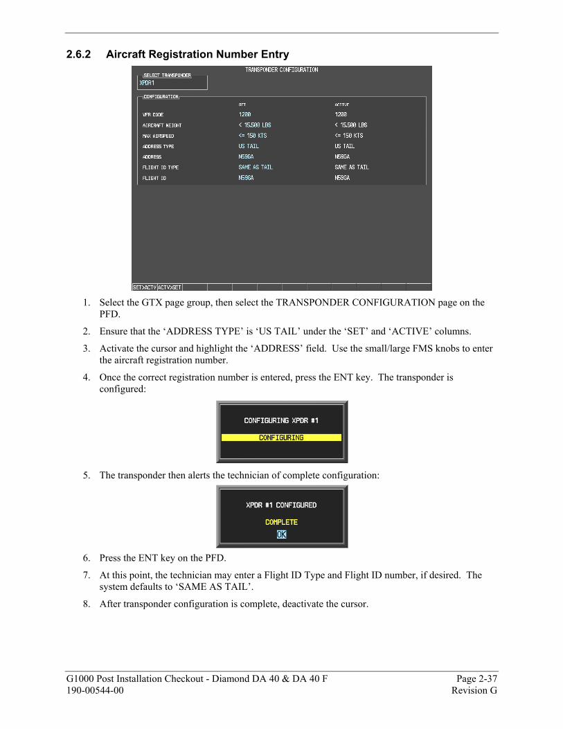
2.6.2 Aircraft Registration Number Entry
1. Select the GTX page group, then select the TRANSPONDER CONFIGURATION page on the
PFD.
2. Ensure that the ‘ADDRESS TYPE’ is ‘US TAIL’ under the ‘SET’ and ‘ACTIVE’ columns.
3. Activate the cursor and highlight the ‘ADDRESS’ field. Use the small/large FMS knobs to enter the aircraft registration number.
4. Once the correct registration number is entered, press the ENT key. The transponder is configured:
5. The transponder then alerts the technician of complete configuration:
6. Press the ENT key on the PFD.
7. At this point, the technician may enter a Flight ID Type and Flight ID number, if desired. The system defaults to ‘SAME AS TAIL’.
8. After transponder configuration is complete, deactivate the cursor.
Page 2-38 G1000 Post Installation Checkout - Diamond DA 40 & DA 40 F Revision G 190-00544-00
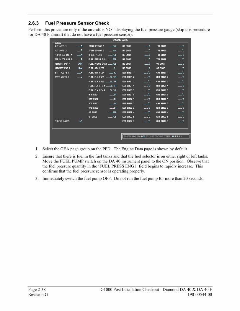
2.6.3 Fuel Pressure Sensor Check Perform this procedure only if the aircraft is NOT displaying the fuel pressure gauge (skip this procedure for DA 40 F aircraft that do not have a fuel pressure sensor):
1. Select the GEA page group on the PFD. The Engine Data page is shown by default.
2. Ensure that there is fuel in the fuel tanks and that the fuel selector is on either right or left tanks. Move the FUEL PUMP switch on the DA 40 instrument panel to the ON position. Observe that the fuel pressure quantity in the ‘FUEL PRESS ENG1’ field begins to rapidly increase. This confirms that the fuel pressure sensor is operating properly.
3. Immediately switch the fuel pump OFF. Do not run the fuel pump for more than 20 seconds.
G1000 Post Installation Checkout - Diamond DA 40 & DA 40 F Page 2-39 190-00544-00 Revision G
2.6.4 Terrain/Obstacle Database Cards 1. Remove power from the PFD and MFD using the respectively labeled breakers.
2. Insert the Terrain/Obstacle database cards (optional) into the lower slots of the MFD and PFD. Refer to the G1000/DA40 Required Equipment List for correct card part numbers.
3. Continue to the Aviation Database Loading procedure. 2.6.5 Aviation Database Loading
1. Insert an SD card (supplied by Garmin or Diamond) containing the Jeppesen aviation database (data supplied by Jeppesen) into the top slot of the PFD.
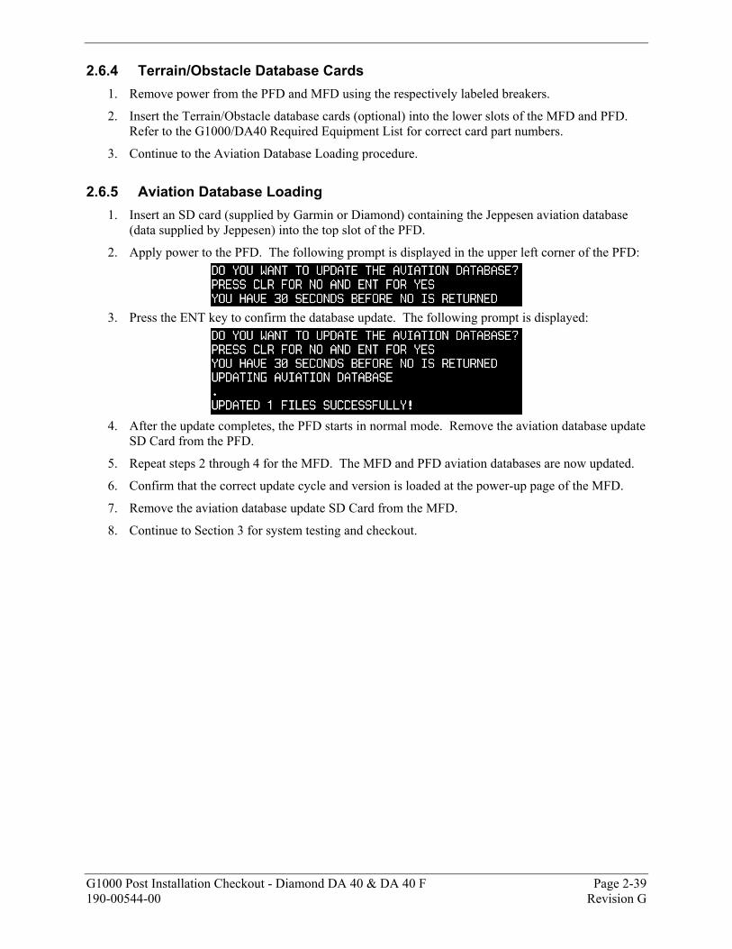
2. Apply power to the PFD. The following prompt is displayed in the upper left corner of the PFD:
3. Press the ENT key to confirm the database update. The following prompt is displayed:
4. After the update completes, the PFD starts in normal mode. Remove the aviation database update
SD Card from the PFD.
5. Repeat steps 2 through 4 for the MFD. The MFD and PFD aviation databases are now updated.
6. Confirm that the correct update cycle and version is loaded at the power-up page of the MFD.
7. Remove the aviation database update SD Card from the MFD.
8. Continue to Section 3 for system testing and checkout.
Page 2-40 G1000 Post Installation Checkout - Diamond DA 40 & DA 40 F Revision G 190-00544-00
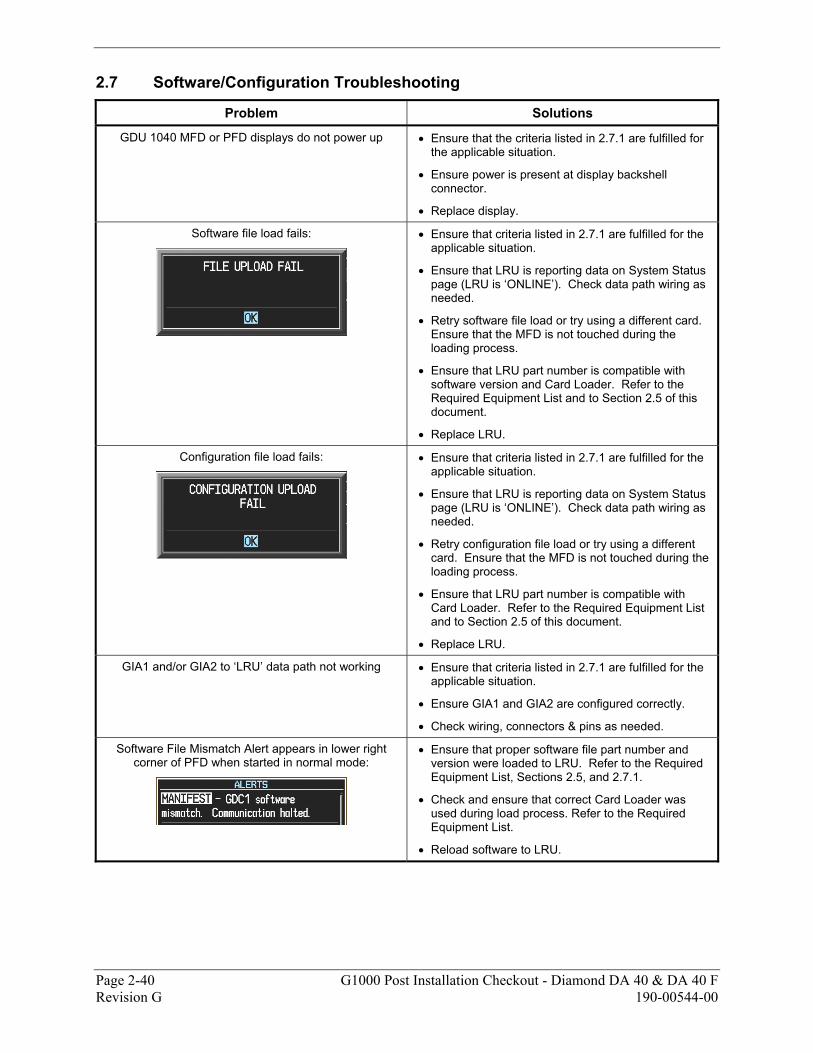
2.7 Software/Configuration Troubleshooting
Problem Solutions
GDU 1040 MFD or PFD displays do not power up • Ensure that the criteria listed in 2.7.1 are fulfilled for the applicable situation.
• Ensure power is present at display backshell connector.
• Replace display.
Software file load fails:
• Ensure that criteria listed in 2.7.1 are fulfilled for the applicable situation.
• Ensure that LRU is reporting data on System Status page (LRU is ‘ONLINE’). Check data path wiring as needed.
• Retry software file load or try using a different card. Ensure that the MFD is not touched during the loading process.
• Ensure that LRU part number is compatible with software version and Card Loader. Refer to the Required Equipment List and to Section 2.5 of this document.
• Replace LRU.
Configuration file load fails:
• Ensure that criteria listed in 2.7.1 are fulfilled for the applicable situation.
• Ensure that LRU is reporting data on System Status page (LRU is ‘ONLINE’). Check data path wiring as needed.
• Retry configuration file load or try using a different card. Ensure that the MFD is not touched during the loading process.
• Ensure that LRU part number is compatible with Card Loader. Refer to the Required Equipment List and to Section 2.5 of this document.
• Replace LRU.
GIA1 and/or GIA2 to ‘LRU’ data path not working • Ensure that criteria listed in 2.7.1 are fulfilled for the applicable situation.
• Ensure GIA1 and GIA2 are configured correctly.
• Check wiring, connectors & pins as needed.
Software File Mismatch Alert appears in lower right corner of PFD when started in normal mode:
• Ensure that proper software file part number and version were loaded to LRU. Refer to the Required Equipment List, Sections 2.5, and 2.7.1.
• Check and ensure that correct Card Loader was used during load process. Refer to the Required Equipment List.
• Reload software to LRU.
G1000 Post Installation Checkout - Diamond DA 40 & DA 40 F Page 2-41 190-00544-00 Revision G
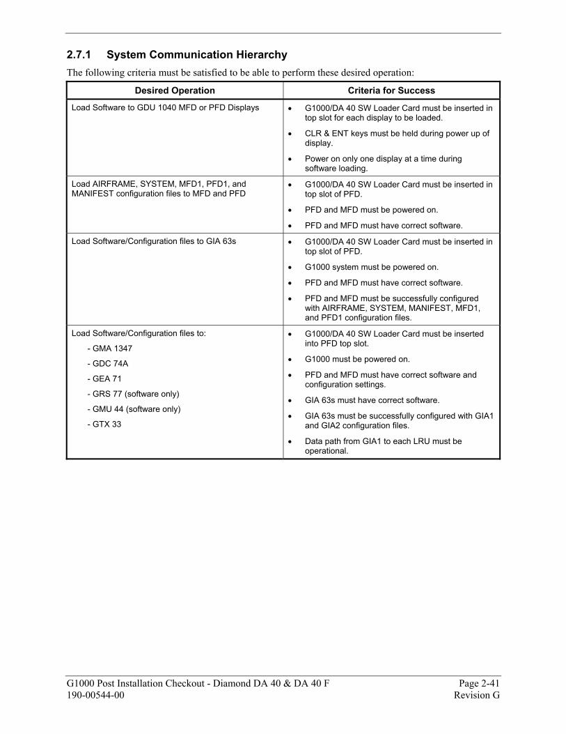
2.7.1 System Communication Hierarchy The following criteria must be satisfied to be able to perform these desired operation:
Desired Operation Criteria for Success
Load Software to GDU 1040 MFD or PFD Displays • G1000/DA 40 SW Loader Card must be inserted in top slot for each display to be loaded.
• CLR & ENT keys must be held during power up of display.
• Power on only one display at a time during software loading.
Load AIRFRAME, SYSTEM, MFD1, PFD1, and MANIFEST configuration files to MFD and PFD
• G1000/DA 40 SW Loader Card must be inserted in top slot of PFD.
• PFD and MFD must be powered on.
• PFD and MFD must have correct software.
Load Software/Configuration files to GIA 63s • G1000/DA 40 SW Loader Card must be inserted in top slot of PFD.
• G1000 system must be powered on.
• PFD and MFD must have correct software.
• PFD and MFD must be successfully configured with AIRFRAME, SYSTEM, MANIFEST, MFD1, and PFD1 configuration files.
Load Software/Configuration files to:
- GMA 1347
- GDC 74A
- GEA 71
- GRS 77 (software only)
- GMU 44 (software only)
- GTX 33
• G1000/DA 40 SW Loader Card must be inserted into PFD top slot.
• G1000 must be powered on.
• PFD and MFD must have correct software and configuration settings.
• GIA 63s must have correct software.
• GIA 63s must be successfully configured with GIA1 and GIA2 configuration files.
• Data path from GIA1 to each LRU must be operational.

Page 2-42 G1000 Post Installation Checkout - Diamond DA 40 & DA 40 F Revision G 190-00544-00
This page intentionally left blank

G1000 Post Installation Checkout - Diamond DA 40 & DA 40 F Page 3-1 190-00544-00 Revision G
3 SYSTEM TESTING & CHECKOUT 3.1 Initial Display Testing
The G1000 system is tested while operating in the normal mode unless otherwise specified. Restart the PFD by cycling the PFD circuit breaker to start the display in the normal mode. Cycle power to the MFD in the same manner.
1. Look at the MFD power-up screen. In the upper right corner, the display shows ‘Diamond DA40 System XXXX.XX’ or ‘Diamond DA40 F System XXXX.XX’
Figure 3-1. MFD Power Up Page
2. This ‘System’ number is the System Software Version. It correlates to the G1000 SW Loader Card used to load the software to the system. For example:
EXAMPLE:
System Software Version ‘0369.06’ = Loader Card P/N 010-00369-06 3. Verify that the System Software Version is correct.
4. Press the ENT key to acknowledge the agreement on the MFD (NOTE: The rightmost softkey may also be used to acknowledge the agreement).
Page 3-2 G1000 Post Installation Checkout - Diamond DA 40 & DA 40 F Revision G 190-00544-00
No. 1 GIA 63
No. 2 GIA 63
No. 1 GIA 63
No. 2 GIA 63
Attitude: GRS 77 AHRSHeading: GRS 77 or GMU 44
GDC 74AAir Data Computer
GTP 59 OAT Probeor GDC 74A ADC
GTX 33 Transponder or#1 & 2 GIA 63
GPS Receivers in #1, 2 GIA 63
No. 1 & 2 GIA 63or GEA 71or Equivalent Engine/Airframe Sensors
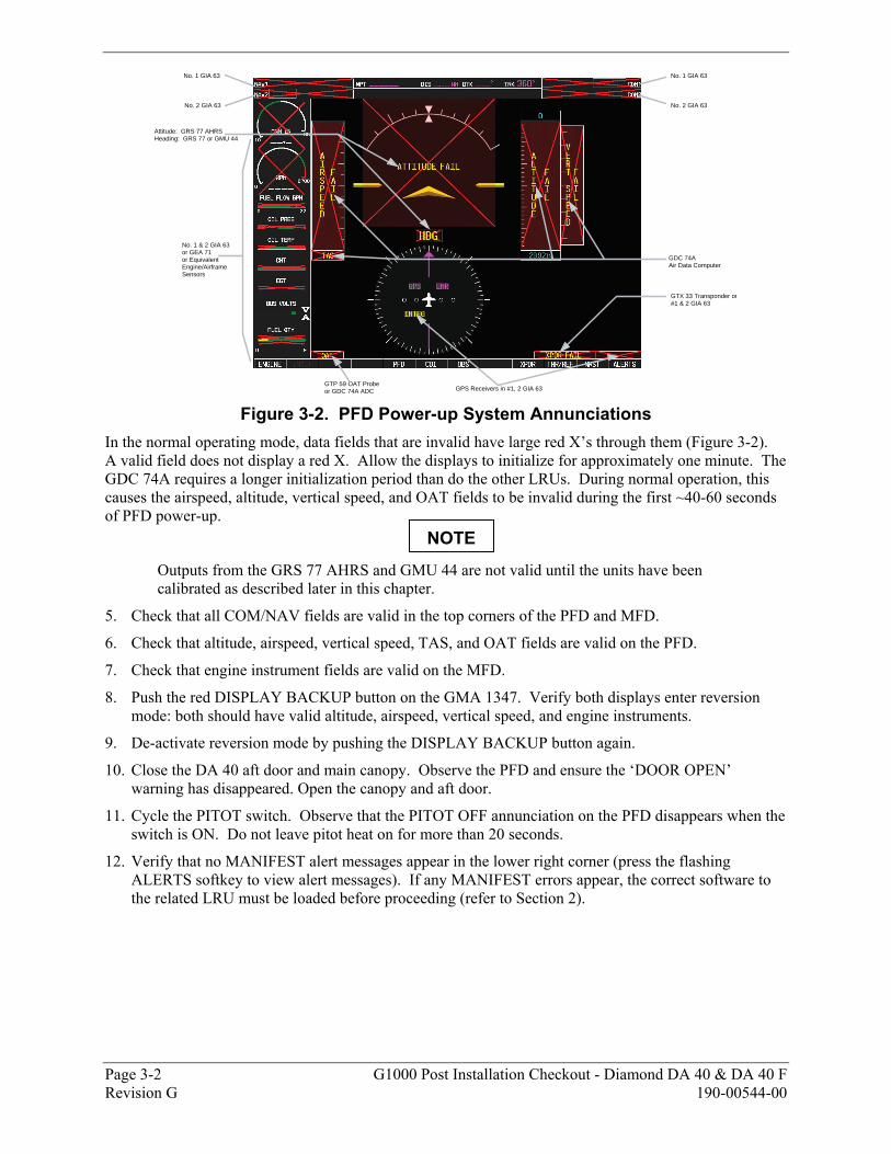
Figure 3-2. PFD Power-up System Annunciations
In the normal operating mode, data fields that are invalid have large red X’s through them (Figure 3-2). A valid field does not display a red X. Allow the displays to initialize for approximately one minute. The GDC 74A requires a longer initialization period than do the other LRUs. During normal operation, this causes the airspeed, altitude, vertical speed, and OAT fields to be invalid during the first ~40-60 seconds of PFD power-up.
Outputs from the GRS 77 AHRS and GMU 44 are not valid until the units have been calibrated as described later in this chapter.
5. Check that all COM/NAV fields are valid in the top corners of the PFD and MFD.
6. Check that altitude, airspeed, vertical speed, TAS, and OAT fields are valid on the PFD.
7. Check that engine instrument fields are valid on the MFD.
8. Push the red DISPLAY BACKUP button on the GMA 1347. Verify both displays enter reversion mode: both should have valid altitude, airspeed, vertical speed, and engine instruments.
9. De-activate reversion mode by pushing the DISPLAY BACKUP button again.
10. Close the DA 40 aft door and main canopy. Observe the PFD and ensure the ‘DOOR OPEN’ warning has disappeared. Open the canopy and aft door.
11. Cycle the PITOT switch. Observe that the PITOT OFF annunciation on the PFD disappears when the switch is ON. Do not leave pitot heat on for more than 20 seconds.
12. Verify that no MANIFEST alert messages appear in the lower right corner (press the flashing ALERTS softkey to view alert messages). If any MANIFEST errors appear, the correct software to the related LRU must be loaded before proceeding (refer to Section 2).
NOTE
G1000 Post Installation Checkout - Diamond DA 40 & DA 40 F Page 3-3 190-00544-00 Revision G
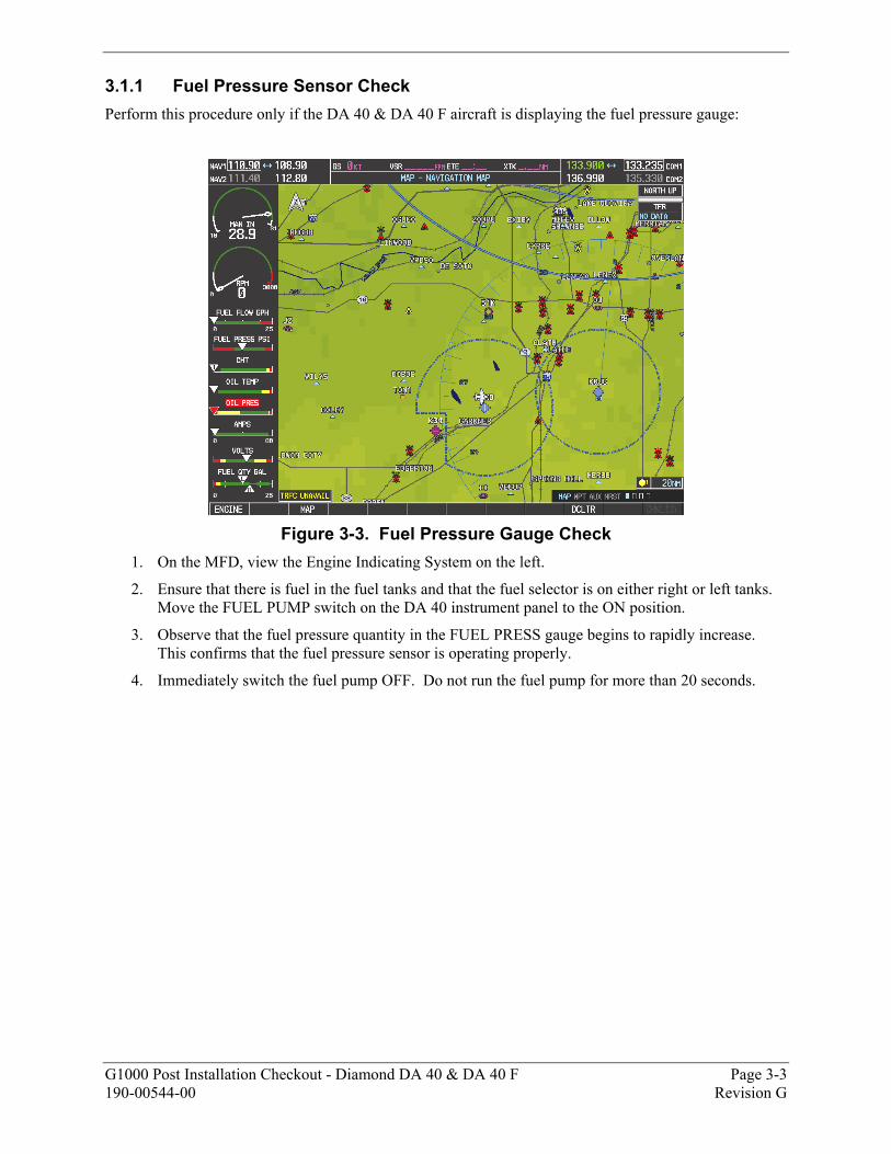
3.1.1 Fuel Pressure Sensor Check Perform this procedure only if the DA 40 & DA 40 F aircraft is displaying the fuel pressure gauge:
Figure 3-3. Fuel Pressure Gauge Check
1. On the MFD, view the Engine Indicating System on the left.
2. Ensure that there is fuel in the fuel tanks and that the fuel selector is on either right or left tanks. Move the FUEL PUMP switch on the DA 40 instrument panel to the ON position.
3. Observe that the fuel pressure quantity in the FUEL PRESS gauge begins to rapidly increase. This confirms that the fuel pressure sensor is operating properly.
4. Immediately switch the fuel pump OFF. Do not run the fuel pump for more than 20 seconds.
Page 3-4 G1000 Post Installation Checkout - Diamond DA 40 & DA 40 F Revision G 190-00544-00
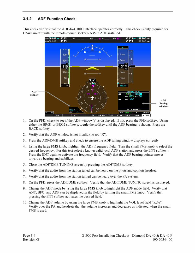
3.1.2 ADF Function Check
This check verifies that the ADF-to-G1000 interface operates correctly. This check is only required for DA40 aircraft with the remote-mount Becker RA3502 ADF installed.
1. On the PFD, check to see if the ADF window(s) is displayed. If not, press the PFD softkey. Using
either the BRG1 or BRG2 softkeys, toggle the softkey until the ADF bearing is shown. Press the BACK softkey.
2. Verify that the ADF window is not invalid (no red ‘X’).
3. Press the ADF/DME softkey and check to ensure the ADF tuning window displays correctly.
4. Using the large FMS knob, highlight the ADF frequency field. Turn the small FMS knob to select the desired frequency. For this test select a known valid local ADF station and press the ENT softkey. Press the ENT again to activate the frequency field. Verify that the ADF bearing pointer moves towards a bearing and stabilizes.
5. Close the ADF/DME TUNING screen by pressing the ADF/DME softkey.
6. Verify that the audio from the station tuned can be heard on the pilots and copilots headset.
7. Verify that the audio from the station turned can be heard over the PA system.
8. On the PFD, press the ADF/DME softkey. Verify that the ADF/DME TUNING screen is displayed.
9. Change the ADF mode by using the large FMS knob to highlight the ADF mode field. Verify that ANT, BFO, and ADF can be displayed in the field by turning the small FMS knob. Verify that pressing the ENT softkey activates the desired field.
10. Change the ADF volume by using the large FMS knob to highlight the VOL level field “xx%”. Verify over the PA and headsets that the volume increases and decreases as indicated when the small FMS is used.
ADF window
ADF Tuning window
G1000 Post Installation Checkout - Diamond DA 40 & DA 40 F Page 3-5 190-00544-00 Revision G
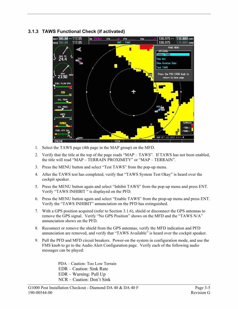
3.1.3 TAWS Functional Check (if activated)
1. Select the TAWS page (4th page in the MAP group) on the MFD.
2. Verify that the title at the top of the page reads “MAP – TAWS”. If TAWS has not been enabled, the title will read “MAP – TERRAIN PROXIMITY” or “MAP – TERRAIN”.
3. Press the MENU button and select “Test TAWS” from the pop-up menu.
4. After the TAWS test has completed, verify that “TAWS System Test Okay” is heard over the cockpit speaker.
5. Press the MENU button again and select “Inhibit TAWS” from the pop-up menu and press ENT. Verify “TAWS INHIBIT “ is displayed on the PFD.
6. Press the MENU button again and select “Enable TAWS” from the prop-up menu and press ENT. Verify the “TAWS INHIBIT” annunciation on the PFD has extinguished.
7. With a GPS position acquired (refer to Section 3.1.6), shield or disconnect the GPS antennas to remove the GPS signal. Verify “No GPS Position” shows on the MFD and the “TAWS N/A” annunciation shows on the PFD.
8. Reconnect or remove the shield from the GPS antennas, verify the MFD indication and PFD annunciation are removed, and verify that “TAWS Available” is heard over the cockpit speaker.
9. Pull the PFD and MFD circuit breakers. Power-on the system in configuration mode, and use the FMS knob to go to the Audio Alert Configuration page. Verify each of the following audio messages can be played:
PDA – Caution: Too Low Terrain EDR – Caution: Sink Rate EDR – Warning: Pull Up NCR – Caution: Don’t Sink
Page 3-6 G1000 Post Installation Checkout - Diamond DA 40 & DA 40 F Revision G 190-00544-00
VCO – Caution: Five Hundred RTC – Caution: Caution, Terrain (2X) RTC – Warning: Terrain (2X), Pull Up (2X) ROC – Caution: Caution, Obstacle (2X) ROC – Warning: Obstacle (2X), Pull Up (2X) ITI – Caution: Terrain Ahead (2X) ITI – Warning: Terrain Ahead, Pull Up (2X) IOI – Caution: Obstacle Ahead (2X) IOI – Warning: Obstacle Ahead, Pull Up (2X)
10. Pull the MFD and PFD circuit breakers, and power-on the system in the normal operating mode.
G1000 Post Installation Checkout - Diamond DA 40 & DA 40 F Page 3-7 190-00544-00 Revision G
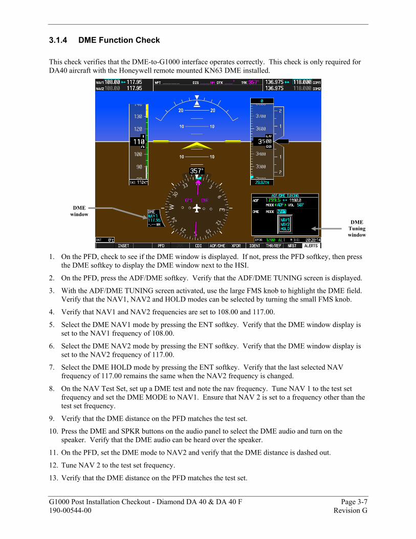
3.1.4 DME Function Check This check verifies that the DME-to-G1000 interface operates correctly. This check is only required for DA40 aircraft with the Honeywell remote mounted KN63 DME installed.
1. On the PFD, check to see if the DME window is displayed. If not, press the PFD softkey, then press
the DME softkey to display the DME window next to the HSI.
2. On the PFD, press the ADF/DME softkey. Verify that the ADF/DME TUNING screen is displayed.
3. With the ADF/DME TUNING screen activated, use the large FMS knob to highlight the DME field. Verify that the NAV1, NAV2 and HOLD modes can be selected by turning the small FMS knob.
4. Verify that NAV1 and NAV2 frequencies are set to 108.00 and 117.00.
5. Select the DME NAV1 mode by pressing the ENT softkey. Verify that the DME window display is set to the NAV1 frequency of 108.00.
6. Select the DME NAV2 mode by pressing the ENT softkey. Verify that the DME window display is set to the NAV2 frequency of 117.00.
7. Select the DME HOLD mode by pressing the ENT softkey. Verify that the last selected NAV frequency of 117.00 remains the same when the NAV2 frequency is changed.
8. On the NAV Test Set, set up a DME test and note the nav frequency. Tune NAV 1 to the test set frequency and set the DME MODE to NAV1. Ensure that NAV 2 is set to a frequency other than the test set frequency.
9. Verify that the DME distance on the PFD matches the test set.
10. Press the DME and SPKR buttons on the audio panel to select the DME audio and turn on the speaker. Verify that the DME audio can be heard over the speaker.
11. On the PFD, set the DME mode to NAV2 and verify that the DME distance is dashed out.
12. Tune NAV 2 to the test set frequency.
13. Verify that the DME distance on the PFD matches the test set.
DME window
DME Tuning window
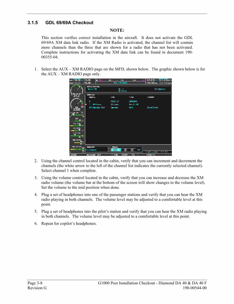
Page 3-8 G1000 Post Installation Checkout - Diamond DA 40 & DA 40 F Revision G 190-00544-00
3.1.5 GDL 69/69A Checkout NOTE:
This section verifies correct installation in the aircraft. It does not activate the GDL 69/69A XM data link radio. If the XM Radio is activated, the channel list will contain more channels than the three that are shown for a radio that has not been activated. Complete instructions for activating the XM data link can be found in document 190-00355-04.
1. Select the AUX – XM RADIO page on the MFD, shown below. The graphic shown below is for
the AUX – XM RADIO page only.
2. Using the channel control located in the cabin, verify that you can increment and decrement the
channels (the white arrow to the left of the channel list indicates the currently selected channel). Select channel 1 when complete.
3. Using the volume control located in the cabin, verify that you can increase and decrease the XM radio volume (the volume bar at the bottom of the screen will show changes to the volume level). Set the volume to the mid position when done.
4. Plug a set of headphones into one of the passenger stations and verify that you can hear the XM radio playing in both channels. The volume level may be adjusted to a comfortable level at this point.
5. Plug a set of headphones into the pilot’s station and verify that you can hear the XM radio playing in both channels. The volume level may be adjusted to a comfortable level at this point.
6. Repeat for copilot’s headphones.
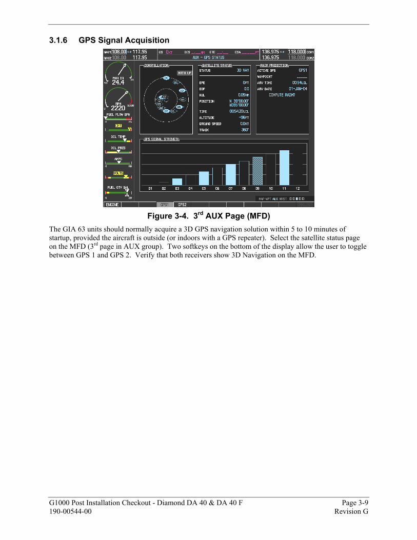
G1000 Post Installation Checkout - Diamond DA 40 & DA 40 F Page 3-9 190-00544-00 Revision G
3.1.6 GPS Signal Acquisition
Figure 3-4. 3rd AUX Page (MFD)
The GIA 63 units should normally acquire a 3D GPS navigation solution within 5 to 10 minutes of startup, provided the aircraft is outside (or indoors with a GPS repeater). Select the satellite status page on the MFD (3rd page in AUX group). Two softkeys on the bottom of the display allow the user to toggle between GPS 1 and GPS 2. Verify that both receivers show 3D Navigation on the MFD.
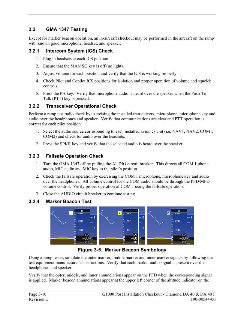
Page 3-10 G1000 Post Installation Checkout - Diamond DA 40 & DA 40 F Revision G 190-00544-00
3.2 GMA 1347 Testing
Except for marker beacon operation, an in-aircraft checkout may be performed in the aircraft on the ramp with known good microphone, headset, and speaker.
3.2.1 Intercom System (ICS) Check 1. Plug in headsets at each ICS position.
2. Ensure that the MAN SQ key is off (no light).
3. Adjust volume for each position and verify that the ICS is working properly.
4. Check Pilot and Copilot ICS positions for isolation and proper operation of volume and squelch controls.
5. Press the PA key. Verify that microphone audio is heard over the speaker when the Push-To-Talk (PTT) key is pressed.
3.2.2 Transceiver Operational Check Perform a ramp test radio check by exercising the installed transceivers, microphone, microphone key and audio over the headphones and speaker. Verify that communications are clear and PTT operation is correct for each pilot position.
1. Select the audio source corresponding to each installed avionics unit (i.e. NAV1, NAV2, COM1, COM2) and check for audio over the headsets.
2. Press the SPKR key and verify that the selected audio is heard over the speaker.
3.2.3 Failsafe Operation Check 1. Turn the GMA 1347 off by pulling the AUDIO circuit breaker. This directs all COM 1 phone
audio, MIC audio and MIC key to the pilot’s position.
2. Check the failsafe operation by exercising the COM 1 microphone, microphone key and audio over the headphones. All volume control for the COM audio should be through the PFD/MFD volume control. Verify proper operation of COM 1 using the failsafe operation.
3. Close the AUDIO circuit breaker to continue testing.
3.2.4 Marker Beacon Test
Figure 3-5. Marker Beacon Symbology
Using a ramp tester, simulate the outer marker, middle marker and inner marker signals by following the test equipment manufacturer’s instructions. Verify that each marker audio signal is present over the headphones and speaker.
Verify that the outer, middle, and inner annunciations appear on the PFD when the corresponding signal is applied. Marker beacon annunciations appear at the upper left corner of the altitude indicator on the
G1000 Post Installation Checkout - Diamond DA 40 & DA 40 F Page 3-11 190-00544-00 Revision G
PFD (Figure 3-5). Operate the MKR MUTE key on the GMA 1347 and ensure that the audio signal is muted.
3.3 GIA 63 Testing
The following section applies to both GIA 63 units. Any differences in testing will be noted.
3.3.1 VHF COM Interference Test This test must be conducted outside. Use of a GPS repeater inside a hangar may result in a failed test. This procedure assumes that the system is currently set to 25 kHz COM channel spacing. Once the signal acquisition test from Section 3.1.6 has been completed successfully, perform the following steps:
1. On the MFD, monitor GPS signal strength bars on the 3rd AUX page.
2. On the PFD, ensure that the CDI is set to GPS. If it is not, press the ‘CDI’ softkey until GPS ENR is displayed.
3. Verify that the GPS “INTEG” flag is out of view.
4. Select 121.150 MHz on the No. 1 COM transceiver.
5. Transmit for a period of 35 seconds while monitoring GPS 1 signal strength levels.
6. During the transmit period, verify that the GPS “INTEG” flag does not come into view on the PFD and verify that GPS 1 does not lose a 3-D navigation solution on the MFD.
7. Repeat steps 5 and 6 and re-transmit while monitoring GPS 2 signal levels on the MFD.
8. Repeat steps 4 through 7 for each of the following frequencies:
• 121.175 MHz
• 121.200 MHz
• 131.250 MHz
• 131.275 MHz
• 131.300 MHz
9. Repeat steps 4 through 8 for the No. 2 COM transceiver (GIA2).
10. On the MFD, select the 4th AUX page.
11. Under the COM CONFIG field, change the COM channel spacing from 25 kHz to 8.33 kHz.
12. Go back to the 3rd AUX page.
13. Select 121.185 MHz on the No. 1 COM transceiver.
14. Transmit for a period of 35 seconds while monitoring GPS 1 signal strength levels.
15. During the transmit period, verify that the GPS “INTEG” flag does not come into view on the PFD and verify that GPS 1 does not lose a 3-D navigation solution on the MFD.
16. Repeat steps 14 and 15 and re-transmit while monitoring GPS 2 signal levels on the MFD.
17. Repeat steps 14 through 16 for each of the following frequencies:
• 121.190 MHz
• 130.285 MHz
• 131.290 Mhz
18. Repeat steps 14 through 17 for the No. 2 COM transceiver (GIA2).
19. On the MFD, select the 4th AUX page and change the COM channel spacing back to 25 kHz.
Page 3-12 G1000 Post Installation Checkout - Diamond DA 40 & DA 40 F Revision G 190-00544-00
3.3.2 VOR/LOC/GS Test Check the VOR, ILS, and Glideslope functions with ramp test equipment. Operate the equipment according to the test equipment manufacturer’s instructions. Adjust the RF signal to a level adequate to perform the test. Select the appropriate HSI source by using the CDI softkey.
The PFD HSI does not show a course deviation bar unless a valid VHF nav frequency is tuned.
Simulate a VOR signal on radial 360° with a course-width of 20°. Verify full scale deflection of the CDI while applying a 10° deviation signal. Exercise the CDI with both right and left deviations for both NAV 1 and 2. Exercise the Glideslope deviation indicator with up and down deviation indications.
3.3.3 COM Antenna VSWR Checks Check for insertion loss and VSWR (Voltage Standing Wave Ratio). VSWR should be checked with an in-line type VSWR/wattmeter inserted in the coaxial transmission line between the transceiver and the antenna. The VSWR should be inserted as close to the transceiver as possible. Any problem with the antenna installation is most likely seen as high reflected power. A VSWR of 3:1 may result in up to a 50% loss in transmit power. Ideally, the VSWR should be 2.5:1 or less.
3.4 GTX 33 Testing
Operation of the GTX 33 Mode-S transponder is accomplished using the G1000 PFD. Refer to the G1000/DA40 Cockpit Reference Guide for basic operation. Perform a basic operational check on the transponder.
The integrated transponder/altitude reporting system must be verified in accordance with Title 14 of the Code of Federal Regulations (CFR) §§ 91.411 and 91.413. This test requires the use of a Mode S ramp generator. Specific instructions for operating the ramp tester are contained in the applicable operator's manual. Refer to Title 14 CFR Part 43 Appendix F for testing criteria.
NOTE
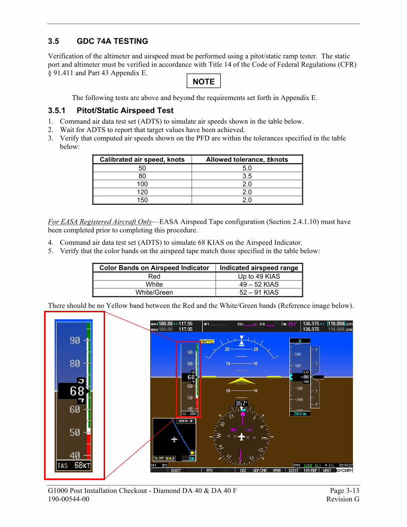
G1000 Post Installation Checkout - Diamond DA 40 & DA 40 F Page 3-13 190-00544-00 Revision G
3.5 GDC 74A TESTING
Verification of the altimeter and airspeed must be performed using a pitot/static ramp tester. The static port and altimeter must be verified in accordance with Title 14 of the Code of Federal Regulations (CFR) § 91.411 and Part 43 Appendix E.
The following tests are above and beyond the requirements set forth in Appendix E.
3.5.1 Pitot/Static Airspeed Test 1. Command air data test set (ADTS) to simulate air speeds shown in the table below. 2. Wait for ADTS to report that target values have been achieved. 3. Verify that computed air speeds shown on the PFD are within the tolerances specified in the table
below:
Calibrated air speed, knots Allowed tolerance, ±knots 50 5.0 80 3.5 100 2.0 120 2.0 150 2.0
For EASA Registered Aircraft Only—EASA Airspeed Tape configuration (Section 2.4.1.10) must have been completed prior to completing this procedure.
4. Command air data test set (ADTS) to simulate 68 KIAS on the Airspeed Indicator. 5. Verify that the color bands on the airspeed tape match those specified in the table below:
Color Bands on Airspeed Indicator Indicated airspeed range Red Up to 49 KIAS
White 49 – 52 KIAS White/Green 52 – 91 KIAS
There should be no Yellow band between the Red and the White/Green bands (Reference image below).
NOTE
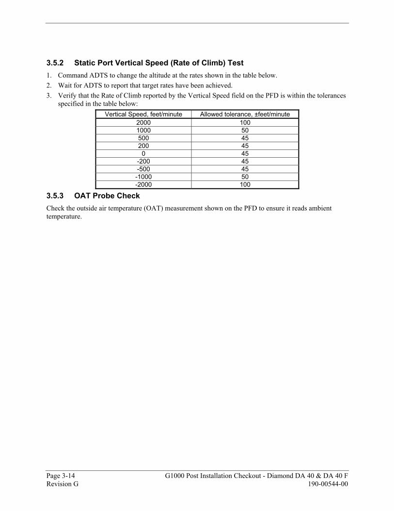
Page 3-14 G1000 Post Installation Checkout - Diamond DA 40 & DA 40 F Revision G 190-00544-00
3.5.2 Static Port Vertical Speed (Rate of Climb) Test 1. Command ADTS to change the altitude at the rates shown in the table below. 2. Wait for ADTS to report that target rates have been achieved. 3. Verify that the Rate of Climb reported by the Vertical Speed field on the PFD is within the tolerances
specified in the table below: Vertical Speed, feet/minute Allowed tolerance, ±feet/minute
2000 100 1000 50 500 45 200 45
0 45 -200 45 -500 45 -1000 50 -2000 100
3.5.3 OAT Probe Check Check the outside air temperature (OAT) measurement shown on the PFD to ensure it reads ambient temperature.
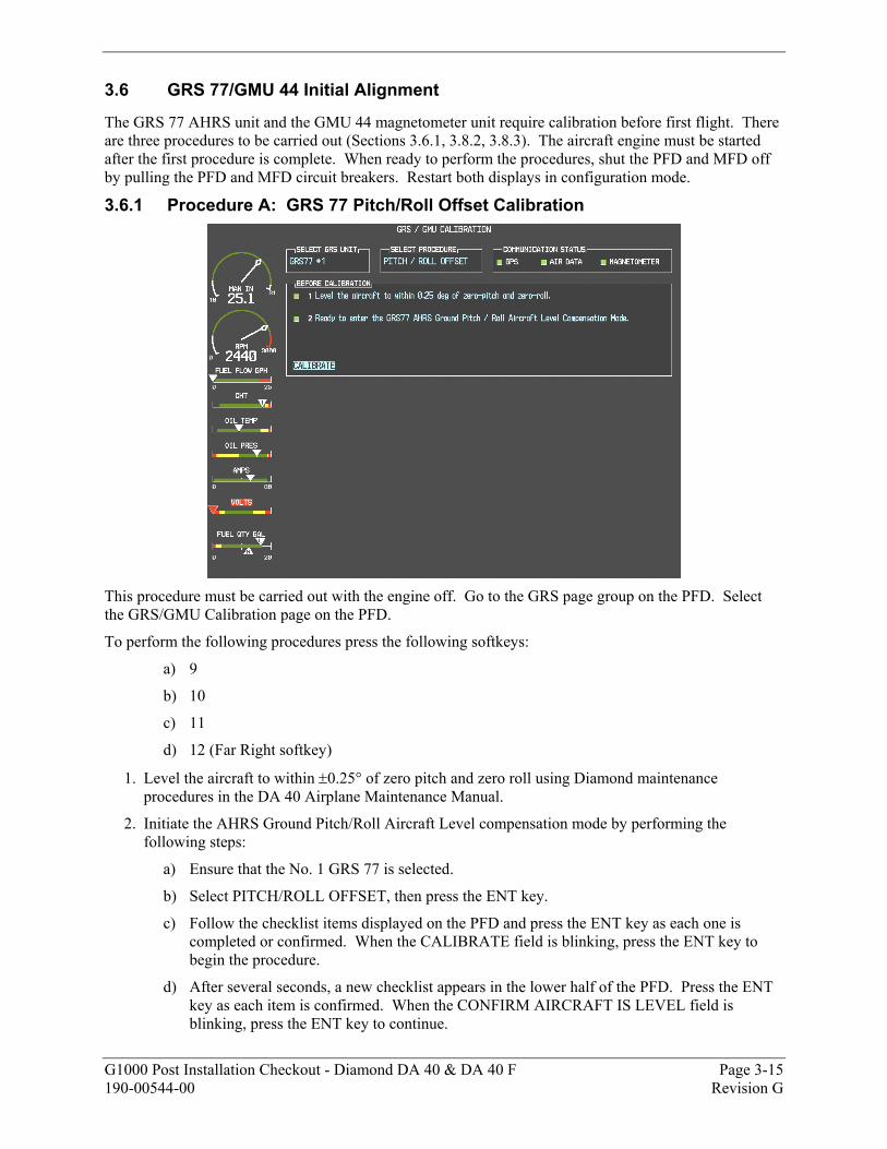
G1000 Post Installation Checkout - Diamond DA 40 & DA 40 F Page 3-15 190-00544-00 Revision G
3.6 GRS 77/GMU 44 Initial Alignment
The GRS 77 AHRS unit and the GMU 44 magnetometer unit require calibration before first flight. There are three procedures to be carried out (Sections 3.6.1, 3.8.2, 3.8.3). The aircraft engine must be started after the first procedure is complete. When ready to perform the procedures, shut the PFD and MFD off by pulling the PFD and MFD circuit breakers. Restart both displays in configuration mode.
3.6.1 Procedure A: GRS 77 Pitch/Roll Offset Calibration
This procedure must be carried out with the engine off. Go to the GRS page group on the PFD. Select the GRS/GMU Calibration page on the PFD.
To perform the following procedures press the following softkeys:
a) 9
b) 10
c) 11
d) 12 (Far Right softkey)
1. Level the aircraft to within ±0.25° of zero pitch and zero roll using Diamond maintenance procedures in the DA 40 Airplane Maintenance Manual.
2. Initiate the AHRS Ground Pitch/Roll Aircraft Level compensation mode by performing the following steps:
a) Ensure that the No. 1 GRS 77 is selected.
b) Select PITCH/ROLL OFFSET, then press the ENT key.
c) Follow the checklist items displayed on the PFD and press the ENT key as each one is completed or confirmed. When the CALIBRATE field is blinking, press the ENT key to begin the procedure.
d) After several seconds, a new checklist appears in the lower half of the PFD. Press the ENT key as each item is confirmed. When the CONFIRM AIRCRAFT IS LEVEL field is blinking, press the ENT key to continue.
Page 3-16 G1000 Post Installation Checkout - Diamond DA 40 & DA 40 F Revision G 190-00544-00
3. The result of the pitch/roll offset compensation is displayed on the PFD. If successful, the AHRS records the required pitch and roll offsets, informs the operator of a successful conclusion and returns to normal operation.
4. Press the ENT key on the PFD to conclude this procedure.
5. Restart both displays in normal mode and proceed to Section 3.7.
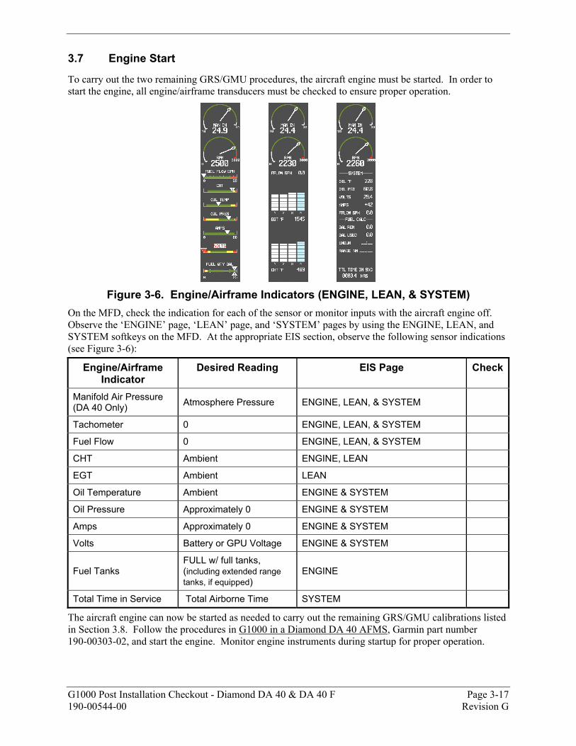
G1000 Post Installation Checkout - Diamond DA 40 & DA 40 F Page 3-17 190-00544-00 Revision G
3.7 Engine Start
To carry out the two remaining GRS/GMU procedures, the aircraft engine must be started. In order to start the engine, all engine/airframe transducers must be checked to ensure proper operation.
Figure 3-6. Engine/Airframe Indicators (ENGINE, LEAN, & SYSTEM)
On the MFD, check the indication for each of the sensor or monitor inputs with the aircraft engine off. Observe the ‘ENGINE’ page, ‘LEAN’ page, and ‘SYSTEM’ pages by using the ENGINE, LEAN, and SYSTEM softkeys on the MFD. At the appropriate EIS section, observe the following sensor indications (see Figure 3-6):
Engine/Airframe Indicator
Desired Reading EIS Page Check
Manifold Air Pressure (DA 40 Only) Atmosphere Pressure ENGINE, LEAN, & SYSTEM
Tachometer 0 ENGINE, LEAN, & SYSTEM
Fuel Flow 0 ENGINE, LEAN, & SYSTEM
CHT Ambient ENGINE, LEAN
EGT Ambient LEAN
Oil Temperature Ambient ENGINE & SYSTEM
Oil Pressure Approximately 0 ENGINE & SYSTEM
Amps Approximately 0 ENGINE & SYSTEM
Volts Battery or GPU Voltage ENGINE & SYSTEM
Fuel Tanks FULL w/ full tanks, (including extended range tanks, if equipped)
ENGINE
Total Time in Service Total Airborne Time SYSTEM
The aircraft engine can now be started as needed to carry out the remaining GRS/GMU calibrations listed in Section 3.8. Follow the procedures in G1000 in a Diamond DA 40 AFMS, Garmin part number 190-00303-02, and start the engine. Monitor engine instruments during startup for proper operation.
Page 3-18 G1000 Post Installation Checkout - Diamond DA 40 & DA 40 F Revision G 190-00544-00
3.8 Final GRS 77/GMU 44 Calibration Procedures The Magnetometer Calibration Procedure (Calibration Procedure B) must be carried out at a site that is determined to be free of magnetic disturbances. If it is unsure whether the site is ‘clean’ the technician should verify that the site is ‘clean’ by following the guidance provided in Section 3.8.1. The technician may skip Section 3.8.1 if the site condition is acceptable. 3.8.1 Site Evaluation of Magnetic Disturbances for Magnetometer Calibration
Procedure (Optional)
Typically, a compass rose is an acceptable location to perform the magnetometer calibration procedure. However, because not all compass roses are well maintained, even an existing compass rose should be regularly evaluated using the method described here to determine if it is free of magnetic disturbances. If evaluation of an existing compass rose indicates that magnetic disturbances are present, then an alternative location must be found to perform the Magnetometer Calibration Procedure.
A G1000-equipped DA 40 airplane can be used to evaluate a candidate site for magnetic disturbances and determine whether it is a suitable location to perform the magnetometer calibration procedure. The magnetometer calibration procedure itself contains the logic to simultaneously survey the location for magnetic cleanliness while it is computing the magnetometer calibration parameters.
The G1000-equipped DA 40 used to evaluate the site must have already completed the pitch/roll offset compensation procedure (Procedure A). However, prior completion of the Magnetometer Calibration Procedure (Procedure B) is not required.
In order to evaluate a candidate site, the Magnetometer Calibration Procedure must be performed twice: once turning clockwise around the site, and once turning counter-clockwise. Both times, the procedure should be conducted as described in Section 3.8.2 of this document, with the exception of the direction of turns around the site.
Although Section 3.8.2 indicates that the Magnetometer Calibration Procedure should be performed by making a series of clockwise turns around the site, the procedure can also be performed by making counter-clockwise turns for the purpose of evaluating the site for magnetic disturbances.
If, upon completion of the Magnetometer Calibration Procedure in each clockwise and counter-clockwise direction, the PFD displays the “CALIBRATION SUCCESSFUL / SITE IS CLEAN” message, then the candidate site is sufficiently free of magnetic disturbances and is acceptable for performing the Magnetometer Calibration Procedure. It is important to obtain successful result in both the clockwise and counter-clockwise directions to ensure that the magnetometer sweeps over a large enough area at the candidate site.
If, upon completion of the Magnetometer Calibration Procedure in either of the two directions, the PFD displays either the “MAG FIELD AT SITE NOT UNIFORM”, or “MAG FIELD AT SITE DIFFERS FROM IGRF MODEL” message, then the site contains magnetic disturbances that are too large.
NOTE
NOTE
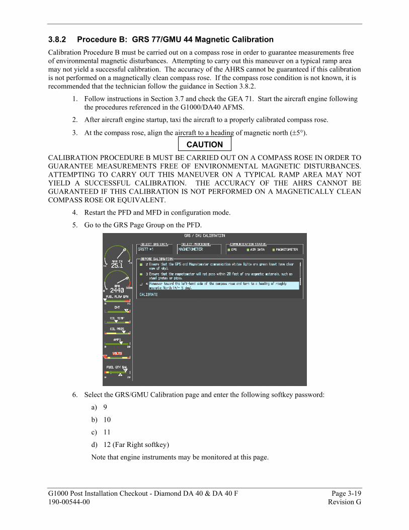
G1000 Post Installation Checkout - Diamond DA 40 & DA 40 F Page 3-19 190-00544-00 Revision G
3.8.2 Procedure B: GRS 77/GMU 44 Magnetic Calibration Calibration Procedure B must be carried out on a compass rose in order to guarantee measurements free of environmental magnetic disturbances. Attempting to carry out this maneuver on a typical ramp area may not yield a successful calibration. The accuracy of the AHRS cannot be guaranteed if this calibration is not performed on a magnetically clean compass rose. If the compass rose condition is not known, it is recommended that the technician follow the guidance in Section 3.8.2.
1. Follow instructions in Section 3.7 and check the GEA 71. Start the aircraft engine following the procedures referenced in the G1000/DA40 AFMS.
2. After aircraft engine startup, taxi the aircraft to a properly calibrated compass rose.
3. At the compass rose, align the aircraft to a heading of magnetic north (±5°).
CALIBRATION PROCEDURE B MUST BE CARRIED OUT ON A COMPASS ROSE IN ORDER TO GUARANTEE MEASUREMENTS FREE OF ENVIRONMENTAL MAGNETIC DISTURBANCES. ATTEMPTING TO CARRY OUT THIS MANEUVER ON A TYPICAL RAMP AREA MAY NOT YIELD A SUCCESSFUL CALIBRATION. THE ACCURACY OF THE AHRS CANNOT BE GUARANTEED IF THIS CALIBRATION IS NOT PERFORMED ON A MAGNETICALLY CLEAN COMPASS ROSE OR EQUIVALENT.
4. Restart the PFD and MFD in configuration mode.
5. Go to the GRS Page Group on the PFD.
6. Select the GRS/GMU Calibration page and enter the following softkey password:
a) 9
b) 10
c) 11
d) 12 (Far Right softkey)
Note that engine instruments may be monitored at this page.
CAUTION
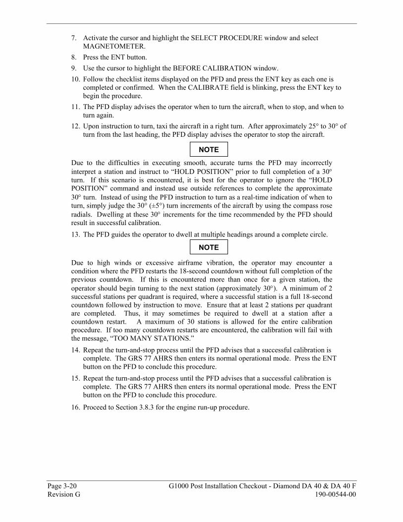
Page 3-20 G1000 Post Installation Checkout - Diamond DA 40 & DA 40 F Revision G 190-00544-00
7. Activate the cursor and highlight the SELECT PROCEDURE window and select MAGNETOMETER.
8. Press the ENT button. 9. Use the cursor to highlight the BEFORE CALIBRATION window. 10. Follow the checklist items displayed on the PFD and press the ENT key as each one is
completed or confirmed. When the CALIBRATE field is blinking, press the ENT key to begin the procedure.
11. The PFD display advises the operator when to turn the aircraft, when to stop, and when to turn again.
12. Upon instruction to turn, taxi the aircraft in a right turn. After approximately 25° to 30° of turn from the last heading, the PFD display advises the operator to stop the aircraft.
Due to the difficulties in executing smooth, accurate turns the PFD may incorrectly interpret a station and instruct to “HOLD POSITION” prior to full completion of a 30° turn. If this scenario is encountered, it is best for the operator to ignore the “HOLD POSITION” command and instead use outside references to complete the approximate 30° turn. Instead of using the PFD instruction to turn as a real-time indication of when to turn, simply judge the 30° (±5°) turn increments of the aircraft by using the compass rose radials. Dwelling at these 30° increments for the time recommended by the PFD should result in successful calibration. 13. The PFD guides the operator to dwell at multiple headings around a complete circle.
Due to high winds or excessive airframe vibration, the operator may encounter a condition where the PFD restarts the 18-second countdown without full completion of the previous countdown. If this is encountered more than once for a given station, the operator should begin turning to the next station (approximately 30°). A minimum of 2 successful stations per quadrant is required, where a successful station is a full 18-second countdown followed by instruction to move. Ensure that at least 2 stations per quadrant are completed. Thus, it may sometimes be required to dwell at a station after a countdown restart. A maximum of 30 stations is allowed for the entire calibration procedure. If too many countdown restarts are encountered, the calibration will fail with the message, “TOO MANY STATIONS.” 14. Repeat the turn-and-stop process until the PFD advises that a successful calibration is
complete. The GRS 77 AHRS then enters its normal operational mode. Press the ENT button on the PFD to conclude this procedure.
15. Repeat the turn-and-stop process until the PFD advises that a successful calibration is complete. The GRS 77 AHRS then enters its normal operational mode. Press the ENT button on the PFD to conclude this procedure.
16. Proceed to Section 3.8.3 for the engine run-up procedure.
NOTE
NOTE
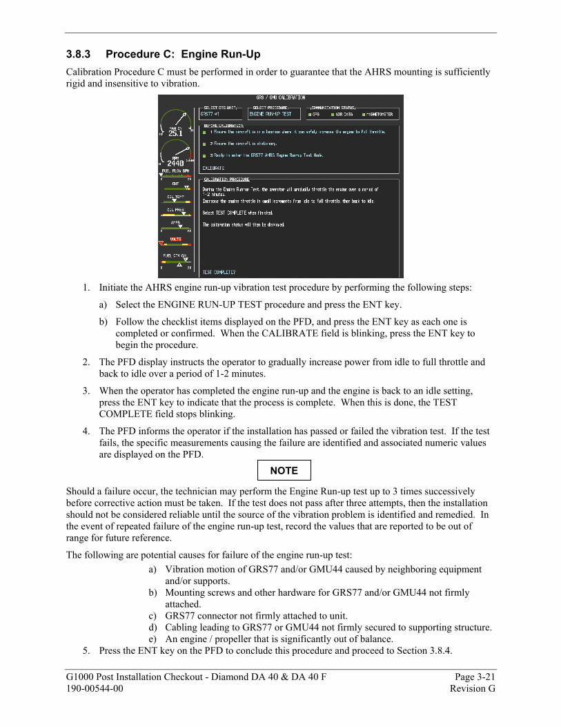
G1000 Post Installation Checkout - Diamond DA 40 & DA 40 F Page 3-21 190-00544-00 Revision G
3.8.3 Procedure C: Engine Run-Up Calibration Procedure C must be performed in order to guarantee that the AHRS mounting is sufficiently rigid and insensitive to vibration.
1. Initiate the AHRS engine run-up vibration test procedure by performing the following steps:
a) Select the ENGINE RUN-UP TEST procedure and press the ENT key.
b) Follow the checklist items displayed on the PFD, and press the ENT key as each one is completed or confirmed. When the CALIBRATE field is blinking, press the ENT key to begin the procedure.
2. The PFD display instructs the operator to gradually increase power from idle to full throttle and back to idle over a period of 1-2 minutes.
3. When the operator has completed the engine run-up and the engine is back to an idle setting, press the ENT key to indicate that the process is complete. When this is done, the TEST COMPLETE field stops blinking.
4. The PFD informs the operator if the installation has passed or failed the vibration test. If the test fails, the specific measurements causing the failure are identified and associated numeric values are displayed on the PFD.
Should a failure occur, the technician may perform the Engine Run-up test up to 3 times successively before corrective action must be taken. If the test does not pass after three attempts, then the installation should not be considered reliable until the source of the vibration problem is identified and remedied. In the event of repeated failure of the engine run-up test, record the values that are reported to be out of range for future reference.
The following are potential causes for failure of the engine run-up test: a) Vibration motion of GRS77 and/or GMU44 caused by neighboring equipment
and/or supports. b) Mounting screws and other hardware for GRS77 and/or GMU44 not firmly
attached. c) GRS77 connector not firmly attached to unit. d) Cabling leading to GRS77 or GMU44 not firmly secured to supporting structure. e) An engine / propeller that is significantly out of balance.
5. Press the ENT key on the PFD to conclude this procedure and proceed to Section 3.8.4.
NOTE
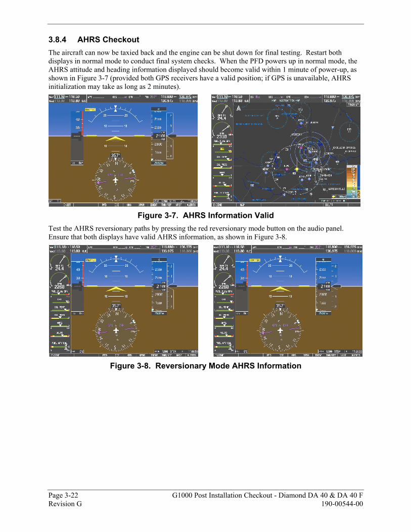
Page 3-22 G1000 Post Installation Checkout - Diamond DA 40 & DA 40 F Revision G 190-00544-00
3.8.4 AHRS Checkout The aircraft can now be taxied back and the engine can be shut down for final testing. Restart both displays in normal mode to conduct final system checks. When the PFD powers up in normal mode, the AHRS attitude and heading information displayed should become valid within 1 minute of power-up, as shown in Figure 3-7 (provided both GPS receivers have a valid position; if GPS is unavailable, AHRS initialization may take as long as 2 minutes).
Figure 3-7. AHRS Information Valid
Test the AHRS reversionary paths by pressing the red reversionary mode button on the audio panel. Ensure that both displays have valid AHRS information, as shown in Figure 3-8.
Figure 3-8. Reversionary Mode AHRS Information
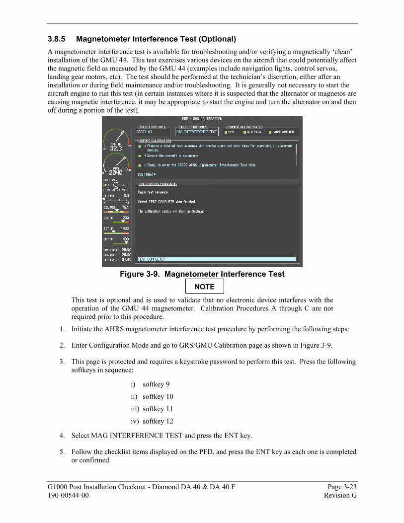
G1000 Post Installation Checkout - Diamond DA 40 & DA 40 F Page 3-23 190-00544-00 Revision G
3.8.5 Magnetometer Interference Test (Optional) A magnetometer interference test is available for troubleshooting and/or verifying a magnetically ‘clean’ installation of the GMU 44. This test exercises various devices on the aircraft that could potentially affect the magnetic field as measured by the GMU 44 (examples include navigation lights, control servos, landing gear motors, etc). The test should be performed at the technician’s discretion, either after an installation or during field maintenance and/or troubleshooting. It is generally not necessary to start the aircraft engine to run this test (in certain instances where it is suspected that the alternator or magnetos are causing magnetic interference, it may be appropriate to start the engine and turn the alternator on and then off during a portion of the test).
Figure 3-9. Magnetometer Interference Test
This test is optional and is used to validate that no electronic device interferes with the operation of the GMU 44 magnetometer. Calibration Procedures A through C are not required prior to this procedure.
1. Initiate the AHRS magnetometer interference test procedure by performing the following steps:
2. Enter Configuration Mode and go to GRS/GMU Calibration page as shown in Figure 3-9.
3. This page is protected and requires a keystroke password to perform this test. Press the following softkeys in sequence:
i) softkey 9
ii) softkey 10
iii) softkey 11
iv) softkey 12
4. Select MAG INTERFERENCE TEST and press the ENT key.
5. Follow the checklist items displayed on the PFD, and press the ENT key as each one is completed or confirmed.
NOTE
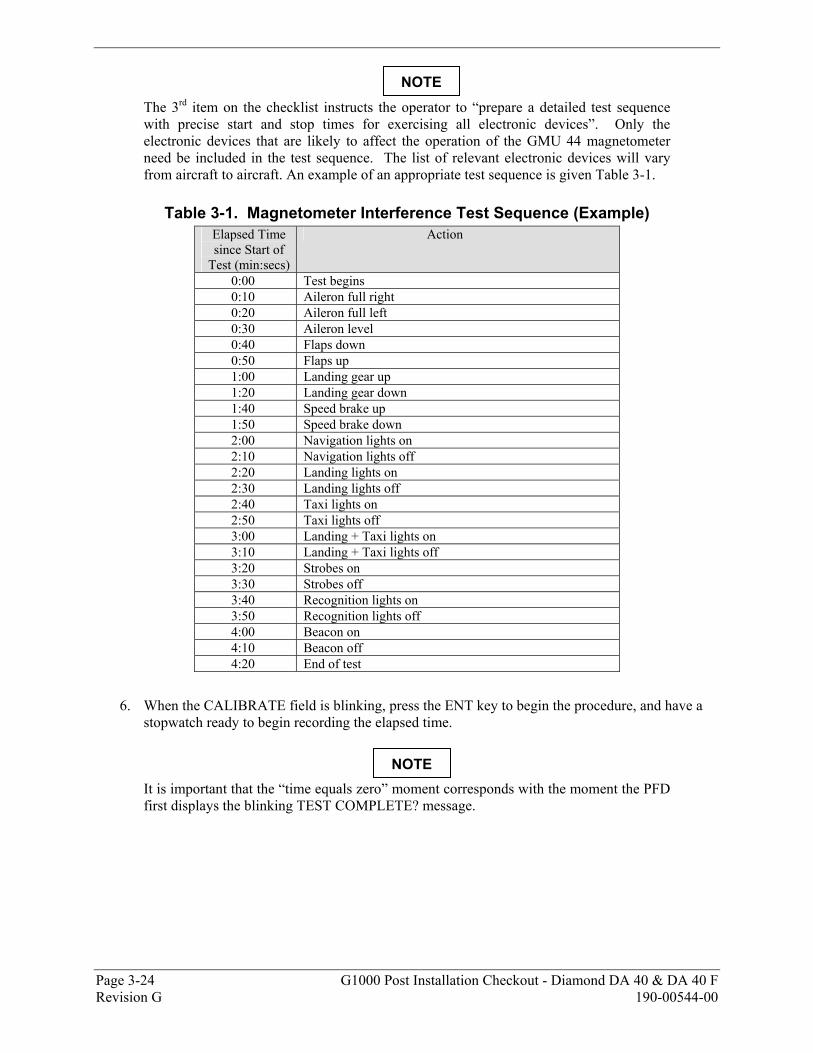
Page 3-24 G1000 Post Installation Checkout - Diamond DA 40 & DA 40 F Revision G 190-00544-00
The 3rd item on the checklist instructs the operator to “prepare a detailed test sequence with precise start and stop times for exercising all electronic devices”. Only the electronic devices that are likely to affect the operation of the GMU 44 magnetometer need be included in the test sequence. The list of relevant electronic devices will vary from aircraft to aircraft. An example of an appropriate test sequence is given Table 3-1.
Table 3-1. Magnetometer Interference Test Sequence (Example) Elapsed Time since Start of
Test (min:secs)
Action
0:00 Test begins 0:10 Aileron full right 0:20 Aileron full left 0:30 Aileron level 0:40 Flaps down 0:50 Flaps up 1:00 Landing gear up 1:20 Landing gear down 1:40 Speed brake up 1:50 Speed brake down 2:00 Navigation lights on 2:10 Navigation lights off 2:20 Landing lights on 2:30 Landing lights off 2:40 Taxi lights on 2:50 Taxi lights off 3:00 Landing + Taxi lights on 3:10 Landing + Taxi lights off 3:20 Strobes on 3:30 Strobes off 3:40 Recognition lights on 3:50 Recognition lights off 4:00 Beacon on 4:10 Beacon off 4:20 End of test
6. When the CALIBRATE field is blinking, press the ENT key to begin the procedure, and have a stopwatch ready to begin recording the elapsed time.
It is important that the “time equals zero” moment corresponds with the moment the PFD first displays the blinking TEST COMPLETE? message.
NOTE
NOTE

G1000 Post Installation Checkout - Diamond DA 40 & DA 40 F Page 3-25 190-00544-00 Revision G
7. The operator should carry out the actions called for in the prepared test sequence.
It is important that all actions are carried out in the order and at the precise elapsed time as specified in the prepared test sequence.
8. When the operator has completed the actions specified in the test sequence, press the ENTER button to indicate that the process is complete. When this is done, the TEST COMPLETE field stops blinking.
9. The PFD informs the operator if the installation has passed or failed the magnetometer interference test. If the test passes, no further action is required for this test.
If the test fails, the installation should be considered unreliable until the source of magnetic interference is identified and remedied. When the magnetometer interference test fails, record the three magnetometer maximum deviation values and their corresponding timestamps. Any maximum deviation value greater than 2.5 milliGauss indicates a problem that must be resolved. Compare the corresponding timestamps with the prepared test sequence to identify which action produced the problem. Contact Garmin for assistance in resolving the problem.
Two common reasons for a failed magnetometer interference test are: 1) new equipment is installed in close proximity to the GMU 44 magnetometer, and 2) an existing or new electronic device has become grounded through the aircraft structure instead of via the proper ground wire in a twisted shielded pair.
10. Press the ENT key on the PFD to conclude this procedure.
NOTE
NOTE
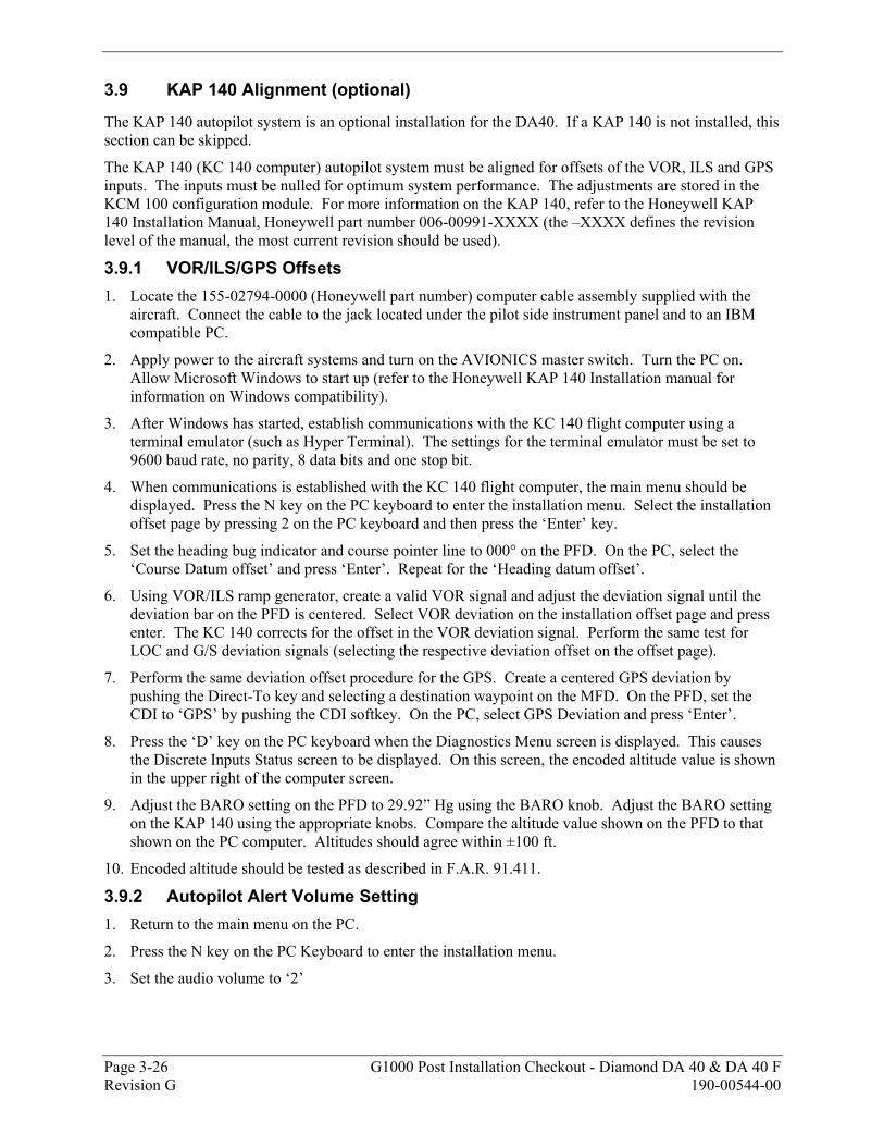
Page 3-26 G1000 Post Installation Checkout - Diamond DA 40 & DA 40 F Revision G 190-00544-00
3.9 KAP 140 Alignment (optional)
The KAP 140 autopilot system is an optional installation for the DA40. If a KAP 140 is not installed, this section can be skipped.
The KAP 140 (KC 140 computer) autopilot system must be aligned for offsets of the VOR, ILS and GPS inputs. The inputs must be nulled for optimum system performance. The adjustments are stored in the KCM 100 configuration module. For more information on the KAP 140, refer to the Honeywell KAP 140 Installation Manual, Honeywell part number 006-00991-XXXX (the –XXXX defines the revision level of the manual, the most current revision should be used).
3.9.1 VOR/ILS/GPS Offsets 1. Locate the 155-02794-0000 (Honeywell part number) computer cable assembly supplied with the
aircraft. Connect the cable to the jack located under the pilot side instrument panel and to an IBM compatible PC.
2. Apply power to the aircraft systems and turn on the AVIONICS master switch. Turn the PC on. Allow Microsoft Windows to start up (refer to the Honeywell KAP 140 Installation manual for information on Windows compatibility).
3. After Windows has started, establish communications with the KC 140 flight computer using a terminal emulator (such as Hyper Terminal). The settings for the terminal emulator must be set to 9600 baud rate, no parity, 8 data bits and one stop bit.
4. When communications is established with the KC 140 flight computer, the main menu should be displayed. Press the N key on the PC keyboard to enter the installation menu. Select the installation offset page by pressing 2 on the PC keyboard and then press the ‘Enter’ key.
5. Set the heading bug indicator and course pointer line to 000° on the PFD. On the PC, select the ‘Course Datum offset’ and press ‘Enter’. Repeat for the ‘Heading datum offset’.
6. Using VOR/ILS ramp generator, create a valid VOR signal and adjust the deviation signal until the deviation bar on the PFD is centered. Select VOR deviation on the installation offset page and press enter. The KC 140 corrects for the offset in the VOR deviation signal. Perform the same test for LOC and G/S deviation signals (selecting the respective deviation offset on the offset page).
7. Perform the same deviation offset procedure for the GPS. Create a centered GPS deviation by pushing the Direct-To key and selecting a destination waypoint on the MFD. On the PFD, set the CDI to ‘GPS’ by pushing the CDI softkey. On the PC, select GPS Deviation and press ‘Enter’.
8. Press the ‘D’ key on the PC keyboard when the Diagnostics Menu screen is displayed. This causes the Discrete Inputs Status screen to be displayed. On this screen, the encoded altitude value is shown in the upper right of the computer screen.
9. Adjust the BARO setting on the PFD to 29.92” Hg using the BARO knob. Adjust the BARO setting on the KAP 140 using the appropriate knobs. Compare the altitude value shown on the PFD to that shown on the PC computer. Altitudes should agree within ±100 ft.
10. Encoded altitude should be tested as described in F.A.R. 91.411.
3.9.2 Autopilot Alert Volume Setting 1. Return to the main menu on the PC.
2. Press the N key on the PC Keyboard to enter the installation menu.
3. Set the audio volume to ‘2’
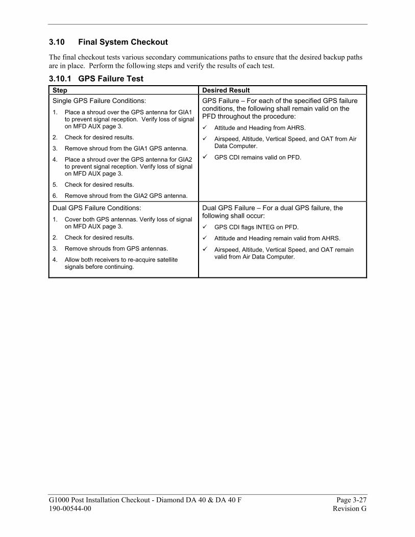
G1000 Post Installation Checkout - Diamond DA 40 & DA 40 F Page 3-27 190-00544-00 Revision G
3.10 Final System Checkout
The final checkout tests various secondary communications paths to ensure that the desired backup paths are in place. Perform the following steps and verify the results of each test.
3.10.1 GPS Failure Test Step Desired Result Single GPS Failure Conditions: 1. Place a shroud over the GPS antenna for GIA1
to prevent signal reception. Verify loss of signal on MFD AUX page 3.
2. Check for desired results.
3. Remove shroud from the GIA1 GPS antenna.
4. Place a shroud over the GPS antenna for GIA2 to prevent signal reception. Verify loss of signal on MFD AUX page 3.
5. Check for desired results.
6. Remove shroud from the GIA2 GPS antenna.
GPS Failure – For each of the specified GPS failure conditions, the following shall remain valid on the PFD throughout the procedure:
Attitude and Heading from AHRS.
Airspeed, Altitude, Vertical Speed, and OAT from Air Data Computer.
GPS CDI remains valid on PFD.
Dual GPS Failure Conditions: 1. Cover both GPS antennas. Verify loss of signal
on MFD AUX page 3.
2. Check for desired results.
3. Remove shrouds from GPS antennas.
4. Allow both receivers to re-acquire satellite signals before continuing.
Dual GPS Failure – For a dual GPS failure, the following shall occur:
GPS CDI flags INTEG on PFD.
Attitude and Heading remain valid from AHRS.
Airspeed, Altitude, Vertical Speed, and OAT remain valid from Air Data Computer.
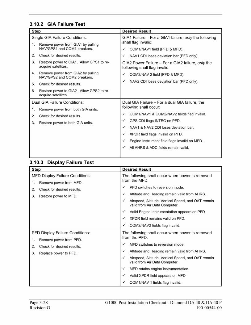
Page 3-28 G1000 Post Installation Checkout - Diamond DA 40 & DA 40 F Revision G 190-00544-00
3.10.2 GIA Failure Test Step Desired Result Single GIA Failure Conditions: 1. Remove power from GIA1 by pulling
NAV/GPS1 and COM1 breakers.
2. Check for desired results.
3. Restore power to GIA1. Allow GPS1 to re-acquire satellites.
4. Remove power from GIA2 by pulling NAV/GPS2 and COM2 breakers.
5. Check for desired results.
6. Restore power to GIA2. Allow GPS2 to re-acquire satellites.
GIA1 Failure – For a GIA1 failure, only the following shall flag invalid:
COM1/NAV1 field (PFD & MFD).
NAV1 CDI loses deviation bar (PFD only).
GIA2 Power Failure – For a GIA2 failure, only the following shall flag invalid:
COM2/NAV 2 field (PFD & MFD).
NAV2 CDI loses deviation bar (PFD only).
Dual GIA Failure Conditions: 1. Remove power from both GIA units.
2. Check for desired results.
3. Restore power to both GIA units.
Dual GIA Failure – For a dual GIA failure, the following shall occur:
COM1/NAV1 & COM2/NAV2 fields flag invalid.
GPS CDI flags INTEG on PFD.
NAV1 & NAV2 CDI loses deviation bar.
XPDR field flags invalid on PFD.
Engine Instrument field flags invalid on MFD.
All AHRS & ADC fields remain valid.
3.10.3 Display Failure Test Step Desired Result MFD Display Failure Conditions: 1. Remove power from MFD.
2. Check for desired results.
3. Restore power to MFD.
The following shall occur when power is removed from the MFD:
PFD switches to reversion mode.
Attitude and Heading remain valid from AHRS.
Airspeed, Altitude, Vertical Speed, and OAT remain valid from Air Data Computer.
Valid Engine Instrumentation appears on PFD.
XPDR field remains valid on PFD.
COM2/NAV2 fields flag invalid.
PFD Display Failure Conditions: 1. Remove power from PFD.
2. Check for desired results.
3. Replace power to PFD.
The following shall occur when power is removed from the PFD:
MFD switches to reversion mode.
Attitude and Heading remain valid from AHRS.
Airspeed, Altitude, Vertical Speed, and OAT remain valid from Air Data Computer.
MFD retains engine instrumentation.
Valid XPDR field appears on MFD
COM1/NAV 1 fields flag invalid.
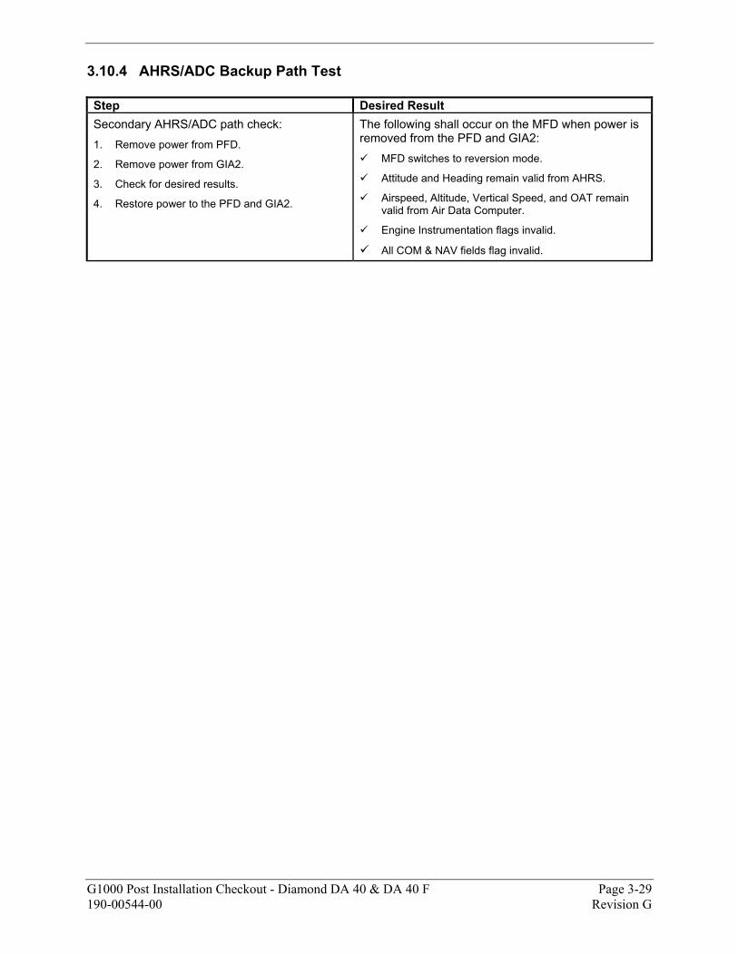
G1000 Post Installation Checkout - Diamond DA 40 & DA 40 F Page 3-29 190-00544-00 Revision G
3.10.4 AHRS/ADC Backup Path Test Step Desired Result Secondary AHRS/ADC path check: 1. Remove power from PFD.
2. Remove power from GIA2.
3. Check for desired results.
4. Restore power to the PFD and GIA2.
The following shall occur on the MFD when power is removed from the PFD and GIA2:
MFD switches to reversion mode.
Attitude and Heading remain valid from AHRS.
Airspeed, Altitude, Vertical Speed, and OAT remain valid from Air Data Computer.
Engine Instrumentation flags invalid.
All COM & NAV fields flag invalid.

Page 3-30 G1000 Post Installation Checkout - Diamond DA 40 & DA 40 F Revision G 190-00544-00
This page intentionally left blank
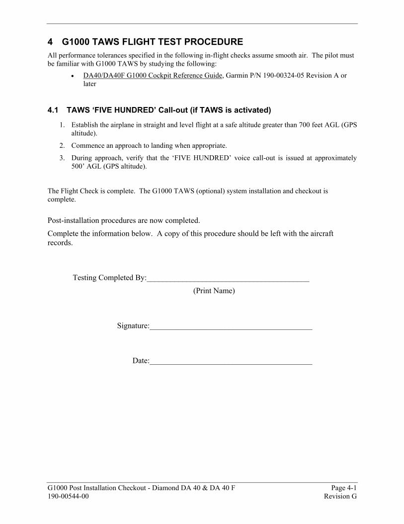
G1000 Post Installation Checkout - Diamond DA 40 & DA 40 F Page 4-1 190-00544-00 Revision G
4 G1000 TAWS FLIGHT TEST PROCEDURE All performance tolerances specified in the following in-flight checks assume smooth air. The pilot must be familiar with G1000 TAWS by studying the following:
• DA40/DA40F G1000 Cockpit Reference Guide, Garmin P/N 190-00324-05 Revision A or later
4.1 TAWS ‘FIVE HUNDRED’ Call-out (if TAWS is activated)
1. Establish the airplane in straight and level flight at a safe altitude greater than 700 feet AGL (GPS altitude).
2. Commence an approach to landing when appropriate.
3. During approach, verify that the ‘FIVE HUNDRED’ voice call-out is issued at approximately 500’ AGL (GPS altitude).
The Flight Check is complete. The G1000 TAWS (optional) system installation and checkout is complete. Post-installation procedures are now completed.
Complete the information below. A copy of this procedure should be left with the aircraft records.
Testing Completed By:_________________________________________
(Print Name)
Signature:_________________________________________
Date:_________________________________________

Page 4-2 G1000 Post Installation Checkout - Diamond DA 40 & DA 40 F Revision G 190-00544-00
This page intentionally left blank.