dialogic pbx integration software reference/media/manuals/docs/pbx_integration_api... · siemens...
TRANSCRIPT

Dialogic® PBX Integration Software Reference
Copyright © 1999-2009 Dialogic Corporation
05-1278-012

Copyright and Legal Notice Copyright © 1999-2009, Dialogic Corporation. All Rights Reserved. You may not reproduce this document in whole or in part without permission in writing from Dialogic Corporation at the address provided below. All contents of this document are furnished for informational use only and are subject to change without notice and do not represent a commitment on the part of Dialogic Corporation or its subsidiaries (“Dialogic”). Reasonable effort is made to ensure the accuracy of the information contained in the document. However, Dialogic does not warrant the accuracy of this information and cannot accept responsibility for errors, inaccuracies or omissions that may be contained in this document. INFORMATION IN THIS DOCUMENT IS PROVIDED IN CONNECTION WITH DIALOGIC® PRODUCTS. NO LICENSE, EXPRESS OR IMPLIED, BY ESTOPPEL OR OTHERWISE, TO ANY INTELLECTUAL PROPERTY RIGHTS IS GRANTED BY THIS DOCUMENT. EXCEPT AS PROVIDED IN A SIGNED AGREEMENT BETWEEN YOU AND DIALOGIC, DIALOGIC ASSUMES NO LIABILITY WHATSOEVER, AND DIALOGIC DISCLAIMS ANY EXPRESS OR IMPLIED WARRANTY, RELATING TO SALE AND/OR USE OF DIALOGIC PRODUCTS INCLUDING LIABILITY OR WARRANTIES RELATING TO FITNESS FOR A PARTICULAR PURPOSE, MERCHANTABILITY, OR INFRINGEMENT OF ANY INTELLECTUAL PROPERTY RIGHT OF A THIRD PARTY. Dialogic products are not intended for use in medical, life saving, life sustaining, critical control or safety systems, or in nuclear facility applications. Due to differing national regulations and approval requirements, certain Dialogic products may be suitable for use only in specific countries, and thus may not function properly in other countries. You are responsible for ensuring that your use of such products occurs only in the countries where such use is suitable. For information on specific products, contact Dialogic Corporation at the address indicated below or on the web at www.dialogic.com. It is possible that the use or implementation of any one of the concepts, applications, or ideas described in this document, in marketing collateral produced by or on web pages maintained by Dialogic may infringe one or more patents or other intellectual property rights owned by third parties. Dialogic does not provide any intellectual property licenses with the sale of Dialogic products other than a license to use such product in accordance with intellectual property owned or validly licensed by Dialogic and no such licenses are provided except pursuant to a signed agreement with Dialogic. More detailed information about such intellectual property is available from Dialogic’s legal department at 9800 Cavendish Blvd., 5th Floor, Montreal, Quebec, Canada H4M 2V9. Dialogic encourages all users of its products to procure all necessary intellectual property licenses required to implement any concepts or applications and does not condone or encourage any intellectual property infringement and disclaims any responsibility related thereto. These intellectual property licenses may differ from country to country and it is the responsibility of those who develop the concepts or applications to be aware of and comply with different national license requirements. Dialogic, Dialogic Pro, Brooktrout, Diva, Cantata, SnowShore, Eicon, Eicon Networks, NMS Communications, NMS (stylized), Eiconcard, SIPcontrol, Diva ISDN, TruFax, Exnet, EXS, SwitchKit, N20, Making Innovation Thrive, Connecting to Growth, Video is the New Voice, Fusion, Vision, PacketMedia, NaturalAccess, NaturalCallControl, NaturalConference, NaturalFax and Shiva, among others as well as related logos, are either registered trademarks or trademarks of Dialogic Corporation or its subsidiaries. Dialogic's trademarks may be used publicly only with permission from Dialogic. Such permission may only be granted by Dialogic’s legal department at 9800 Cavendish Blvd., 5th Floor, Montreal, Quebec, Canada H4M 2V9. Any authorized use of Dialogic's trademarks will be subject to full respect of the trademark guidelines published by Dialogic from time to time and any use of Dialogic’s trademarks requires proper acknowledgement. Windows is a registered trademark of Microsoft Corporation in the United States and/or other countries. Other names of actual companies and product mentioned herein are the trademarks of their respective owners.
Publication Date: January 2009 Document Number: 05-1278-012

Table of Contents 1. How to Use This Manual ................................................................................ 9 1.1. Audience ........................................................................................................ 9 1.2. Dialogic® Voice Hardware Covered by This Manual .................................. 10
1.2.1. Dialogic® Voice Hardware Model Names........................................... 11 1.3. When to Use This Manual ........................................................................... 11 1.4. Documentation Conventions........................................................................ 12 1.5. How This Manual Is Organized ................................................................... 12 2. Using the PBX Functions.............................................................................. 15 2.1. The Dialogic® Unified API .......................................................................... 15 2.2. Switch-Specific Support .............................................................................. 16 3. Unified API Function Reference.................................................................. 19 ATD4_BDTYPE( ) - returns the board type ........................................................ 20 ATD4_CHTYPE( ) - returns the channel type..................................................... 22 d42_brdstatus( ) - retrieves the current board status ............................................ 24 d42_chnstatus( ) - retrieves the current channel status ........................................ 26 d42_dial( ) – dials an ASCIIZ string.................................................................... 28 d42_display( ) - retrieves the current LCD/LED display ..................................... 31 d42_displayex( ) - retrieves the current LCD/LED display ................................. 35 d42_getparm( ) - retrieves the selected channel or board parameter.................... 39 d42_getver( ) - retrieves the board firmware or library version........................... 43 d42_gtcallid( ) - retrieves the called/calling number ID ...................................... 46 d42_gtcallidex( ) - retrieves call information....................................................... 49 d42_indicators( ) - retrieves the current LCD or LED indicators ........................ 52 d42_indicatorsex( ) - retrieves the current LCD or LED indicators..................... 67 d42_setparm( ) - sets a board or channel parameter............................................. 71 4. Programming Considerations ...................................................................... 75 4.1. Opening a Channel on the Dialogic® PBX Integration Board ..................... 75 4.2. Accessing PBX Features Using Dial Strings ............................................... 76
4.2.1. On-Hook and Off-Hook Dialing Note................................................. 77 4.2.2. Turn On the Message Waiting Indicator ............................................. 78 4.2.3. Turn Off the Message Waiting Indicator Dial String .......................... 80 4.2.4. Dial Programmable Keys .................................................................... 82 4.2.5. Transferring a Call............................................................................. 114 4.2.6. In-Band/Out-of-Band Signaling ........................................................ 115 4.2.7. Disconnect Supervision..................................................................... 117
3

Dialogic® PBX Integration Software Reference
4.2.8. Converting Existing D/4x Applications ............................................ 117 Appendix A - Unified API Quick Reference.................................................. 119 Appendix B - Demonstration Programs for Windows®............................... 125
Documentation Conventions ........................................................................ 125 Dialogic® D/42 Demo ........................................................................................ 125
D/42 Demo Requirements ............................................................................ 126 Setup............................................................................................................. 126 Running the Demo........................................................................................ 126
Siemens Optiset MWI Demo ............................................................................. 135 Appendix C - Error Definitions ...................................................................... 139 Appendix D - Asynchronous Event Definitions............................................. 143 Glossary ............................................................................................................ 145 Index.................................................................................................................. 153
4

List of Tables Table 1. Valid Dial String Characters for d42_dial( )......................................... 28 Table 2. Board and Channel Parameters for d42_getparm( ).............................. 40 Table 3. Board and Channel Parameters for d42_setparm( ) .............................. 72 Table 4. Avaya 7434 (4-Wire) Direct Key Dialing Sequences........................... 84 Table 5. Avaya 8434DX (2-Wire) Direct Key Dialing Sequences ..................... 87 Table 6. Siemens ROLMphone 400 Direct Key Dialing Sequences................... 90 Table 7. Siemens Hicom Optiset E Direct Key Dialing Sequences with
Hicom 150 ................................................................................................... 93 Table 8. Siemens Hicom Optiset E Direct Key Dialing Sequences with
Hicom 300 ................................................................................................... 96 Table 9. MITEL SX SUPERSET 420 Direct Key Dialing Sequences ............... 99 Table 10. MITEL SX SUPERSET 430 Direct Key Dialing Sequences ........... 101 Table 11. Nortel Norstar and BCM M7324 Direct Key Dialing Sequences ..... 105 Table 12. Nortel Meridian 1 M2616 Direct Key Dialing Sequences ................ 108 Table 13. NEC KTS/PBX Direct Key Dialing Sequences................................ 111 Table 14. Setting In-Band and Out-of-Band Signaling..................................... 116 Table 15. Demo Indicator Definitions .............................................................. 134
5

Dialogic® PBX Integration Software Reference
6

List of Figures Figure 1. Avaya 7434 (4-Wire) Telephone Indicators ........................................ 55 Figure 2. Avaya 8434 (2-Wire) Telephone Indicators ........................................ 56 Figure 3. ROLMphone 400 Telephone Indicators .............................................. 58 Figure 4. Siemens Optiset E Telephone Indicators ............................................. 60 Figure 5. MITEL SUPERSET 400 Series Telephone Indicators ........................ 62 Figure 6. Nortel Model 7324 Telephone Indicators............................................ 63 Figure 7. Nortel Model 2616 Telephone Indicators............................................ 65 Figure 8. Nortel Model 7324 Telephone Indicators............................................ 69 Figure 9. Avaya 7434 (4-Wire) Telephone......................................................... 83 Figure 10. Avaya 8434 (2-Wire) Telephone....................................................... 86 Figure 11. ROLMphone 400 Telephone ............................................................. 89 Figure 12. Siemens Optiset E Telephone with a Hicom 150 .............................. 92 Figure 13. Siemens Optiset E Telephone with a Hicom 300 .............................. 95 Figure 14. MITEL SUPERSET 420 Telephone.................................................. 98 Figure 15. MITEL SUPERSET 430 Telephone................................................ 101 Figure 16. Nortel M7324 Telephone................................................................. 104 Figure 17. Nortel Meridian 1 M2616 Telephone .............................................. 107 Figure 18. NEC DTerm III Telephone.............................................................. 110 Figure 19. Dialogic D42 Demo Window .......................................................... 127 Figure 20. D42 Options Window...................................................................... 127 Figure 21. Input Strings .................................................................................... 129 Figure 22. Input Strings Warning ..................................................................... 130 Figure 23. Select Your D42 Channel ................................................................ 130 Figure 24. Select Your D42 Channel, Channel List Displayed......................... 131 Figure 25. ROLMphone Window on the D42 Demo........................................ 132 Figure 26. Siemens Optiset MWI Demo Window ............................................ 136 Figure 27. Enter Channel Number .................................................................... 136 Figure 28. Channel Opened Message................................................................ 137 Figure 29. Send Message .................................................................................. 137 Figure 30. Message Sent ................................................................................... 138 Figure 31. Delete Message................................................................................ 138 Figure 32. Message Deleted.............................................................................. 138
7

Dialogic® PBX Integration Software Reference
8

1. How to Use This Manual
1.1. Audience
This manual is intended for programmers and engineers who choose to use Dialogic® D/42 Series software, together with Dialogic® D/4x Voice software, to develop voice and call processing applications on Dialogic® PBX Integration Boards for a PBX system.
When this manual addresses “you,” it means “you, the programmer,” and when this manual refers to the “user,” it means an end-user of an application program.
If you are experienced with voice technology and Dialogic® products, you may prefer to deal strictly with information found in this Dialogic PBX Integration Software Reference
®
, particularly in Sections 3 and 4. These sections contain detailed technical information for programming an application with C language library functions and data structures.
If you are new to Dialogic® products and voice technology, you may prefer to start with the Dialogic Voice API Programming Guide® , which provides an introduction to the Dialogic® Voice products, with explanations and help beyond a strictly technical level so that you can learn the Dialogic® Voice software. This includes descriptions of how one can use the voice processing, signaling, and call progress analysis (CPA) features, and how one can design a multi-line voice application.
NOTE: Dialogic® PBX Integration Boards only support CPA when used in the default routing configuration. For instance, if a voice resource of a Dialogic® D/82JCT-U Board is listening to a front end other than the default (its own), it may return a disconnected result. This is because these boards support the call progress analysis feature of dx_dial( ), only when a board is using the default TDM routing. In other words, PBX Integration Board voice resources cannot be used to provide CPA capability for other boards.
9

Dialogic® PBX Integration Software Reference
1.2. Dialogic® Voice Hardware Covered by This Manual
The Dialogic® PBX Integration Board voice hardware provides a set of cost-effective tools that enable implementation of computerized voice and call processing applications for Private Branch Exchanges (PBXs) and Key Telephone Systems (KTSs). It provides the basic voice and call processing capabilities of Dialogic® D/4x voice hardware, and adds hardware and firmware that can ease integration with supported PBXs and KTSs. Refer to the Dialogic Voice API Programming Guide
®
for more information on voice and call processing.
For simplicity, throughout this manual the term PBX is sometimes used to denote a PBX, a KTS, or a key system unit (KSU).
The Dialogic® PBX integration hardware models covered by this manual include the following Dialogic® boards:
• Dialogic® D/42JCT-U Board – a 4-channel voice-processing board. It has downloadable firmware and a universal digital station set interface that can emulate a number of phones from different vendors. The trunk interface section of the board uses digital PBX signaling link technology to interface with the supported PBXs. The D/42JCT-U Board is in the PCI form factor, and it provides SCbus and H.100 connectivity. The board uses Dialogic® R4 firmware and the Dialogic® Voice and Unified APIs. Support for host-assisted fax is also provided.
• Dialogic® D/82JCT-U Board – an 8-channel voice-processing board. It has downloadable firmware and a universal digital station set interface that can emulate a number of phones from different vendors. The trunk interface section of the board uses digital PBX signaling link technology to interface with the supported PBXs. The D/82JCT-U Board is in the PCI form factor, and it provides SCbus and H.100 connectivity. The board uses Dialogic® R4 firmware and the Dialogic® Voice and Unified APIs. Support for host-assisted fax is also provided.
10

1. How to Use This Manual
1.2.1. Dialogic® Voice Hardware Model Names
Model names for Dialogic® Voice Boards are based upon the following pattern:
D/NNNoRBB-TT-VVV where:
• D/ - identifies the board as Dialogic® voice hardware. • NNN - identifies the number of channels (2, 4, 8, 12, etc.), or relative
size/power measure. • o - 0 indicates no support for call progress analysis; 1 indicates support for
call progress analysis; and 2 indicates PBX support. • R - if present, this represents board revision (D, E, J, etc.). • BB - bus type (SC or CT). • TT - telephony interface type (if applicable; valid entries include LS, T1, E1,
BR, U (for universal PBX Interface)). • VVV - ohm value (if applicable; valid entries are 75 and 120).
Sometimes this document refers to a group of Dialogic® Voice Boards rather than specific models, in which case an “x” is used to replace the part of the model name that is generic. For example, D/xxx refers to all models of the Dialogic®
voice hardware, and D/8x refers to all 8-channel models of the Dialogic® voice hardware.
1.3. When to Use This Manual
This Dialogic PBX Integration Software Reference® contains programming information for those choosing to develop applications in the Linux or Windows® operating system environment using the Dialogic® Unified API and D/42 runtime library. The Unified API provides a single, basic set of high-level calls that can be used to develop applications across a variety of manufacturers’ switches. The D/42 runtime library supports the Unified API and works in conjunction with the Dialogic® Voice library for enabling applications to set up calls and perform PBX call functions using the Dialogic® PBX Integration Board.
11

Dialogic® PBX Integration Software Reference
The sequence for installing Dialogic® software and hardware to develop application programs is as follows:
• Install the Dialogic® PBX Integration Board in a PC according to the Dialogic PBX Integration Quick Install Card® provided with the board.
• Install the Dialogic® System Release Software following the procedures in the Dialogic System Release Software Installation Guide® to include D/42 and voice support.
• Download the Dialogic® PBX Integration firmware to the boards in the system. (On Windows® systems, this is done in the Dialogic® Configuration Manager (DCM). On Linux systems, this is done in the configuration file /usr/dialogic/cfg/dialogic.cfg.)
Refer to this manual, the Dialogic PBX Integration Board User’s Guide® , and the Dialogic Voice API Programming Guide ® to develop application programs.
1.4. Documentation Conventions
The following documentation conventions are used throughout this manual: • When terms are first introduced, they are shown in italic text. • When a word or phrase is emphasized, it is shown in boldface text. • Function parameter names are shown in boldface, as in maxsec. • Function names are shown in boldface with parentheses, such as
d42_display( ).
• Names of defines or equates are shown in uppercase, such as T_DTMF.
• File names are italicized and in uppercase, such as D42DRV.EXE.
1.5. How This Manual Is Organized
Chapter 1 – How to Use This Manual describes the Dialogic PBX Integration Software Reference
®
.
Chapter 2 – Using the PBX Functions provides information on using the Dialogic® Voice library functions with the Dialogic® PBX Integration Board.
12

1. How to Use This Manual
Chapter 3 – Unified API Function Reference provides detailed technical information on the Dialogic® PBX Interface software C language library functions (the Dialogic® Unified API).
Chapter 4 – Programming Considerations contains information about developing applications for the supported PBXs.
Appendix A – Unified API Quick Reference provides concise information on the Dialogic® Unified API C language library functions.
Appendix B – Demonstration Programs for Windows provides instructions for running the
®
Dialogic® D/42 Demonstration Program.
Appendix C – Error Definitions lists and describes error codes.
Appendix D – Asynchronous Event Definitions lists and describes events.
Glossary contains a list of definitions for commonly used terms.
Index contains an alphabetical index of features and topics.
13

Dialogic® PBX Integration Software Reference
14

2. Using the PBX Functions
The PBX circuitry on the Dialogic® PBX Integration Boards provides functions specific to several different PBXs. These functions are implemented using the Dialogic® D/42 runtime library (.dll). The D/42 runtime library is used in addition to the Dialogic® Standard Runtime Library (SRL) when integration and control of the PBX and D/42-xx and PBX Integration Boards are required.
The Dialogic® Voice Library acts as an interface between the application program and the PBX Integration Board hardware. The Voice Library is used to access voice functions such as voice play/record and call progress analysis. Refer to the Dialogic Voice API Library Reference ® for information about using voice functions.
2.1. The Dialogic® Unified API
The Dialogic® Unified API can be used for the development of applications across a variety of manufacturers’ switches (both key and PBX systems) through a single interface. The Unified API provides a single set of functions (refer to Chapter 3. Unified API Function Reference) that can be used for the supported switches and are sent directly to the switch through the Dialogic® PBX Integration Board, without additional hardware. Functioning as an extension to the Dialogic® Voice API, the Unified API offers a single design model that allows developers to implement PBX features (such as called/calling number ID and ASCII display information).
Using the Unified API can shorten development time by eliminating the need to learn separate APIs for each switch. It allows programmers to create applications with a common set of functions, which operate with switches produced by different manufacturers, thereby potentially widening a product’s support beyond the traditional single-switch focus.
Utility functions included in the Unified API allow programmers to control the PBX Integration Board. Application can retrieve the channel type, obtain and set channel parameters, retrieve firmware/driver/library version numbers, and retrieve error information.
15
Dialogic® PBX Integration Software Reference
The Dialogic® D/42 runtime library works in conjunction with the Voice Library to allow applications to set up calls and perform PBX call functions using PBX Integration Boards. In addition, the D/42 runtime library supports the Unified API.
The functions called by the Unified API are synchronous. This means that when a function is called in a thread, it is performed immediately and blocks until the operation is complete. Functions can be called at any time to execute on a channel that is idle or busy, and do not affect the idle or busy state of the channel.
NOTE: Refer to the Dialogic Standard Runtime Library API Programming Guide
®
for a detailed explanation of synchronous functions.
The D/42 runtime library treats boards and channels as separate devices, even though channels are physically part of a board. A channel device is an individual PBX line connection, and a board device is a PBX Integration Board that contains channels. Most functions are performed at the channel level, such as getting called/calling number ID. Certain functions, such as setting board parameters, can occur at the board level and affect all channels on that board.
NOTE: Since boards and channels are considered separate devices under Windows®, it is possible to open and use a channel without opening the board where the channel is located. There is no board-channel hierarchy imposed by the D/42 runtime library.
2.2. Switch-Specific Support
PBX station set phones may come with both standard and programmable keys that give access to switch-specific functions. The most common of these features include:
• Transfer • Hold • Trunk line select • Message waiting indication • Hands-free operation
Refer to the Dialogic PBX Integration Board User’s Guide ® for detailed information about PBX features. Because the Dialogic® PBX Integration Board has the capability to emulate a PBX station set, it can also emulate standard or
16
2. Using the PBX Functions
programmable functions for an application. Applications can use the common features listed here, as well as less frequently used features like conferencing. In addition, applications can reprogram keys as needed. Refer to Chapter 4. Programming Considerations for details about switch-specific programming.
17

Dialogic® PBX Integration Software Reference
18

3. Unified API Function Reference
This chapter provides detailed technical information on the Dialogic® PBX Interface software, C language library functions (the Dialogic® Unified API). The library functions are prototyped in D42LIB.H.
See the Table of Contents for a list of functions. Appendix A provides a quick reference containing a more compact description of the functions that are detailed in this chapter. Only functions compatible with the Dialogic® PBX Integration Board are discussed in this document.
The functions are listed in alphabetical order and provide the following information: Function Header Located at the beginning of each function and contains
the following information: function name, function syntax, input parameters, output or returns, includes (header files required to be included), and mode. The function syntax and inputs include the data type and are shown using standard C language syntax.
Description Provides a detailed description of the function operation, including parameter descriptions.
Cautions Provides warnings and reminders. Example Provides one or more C language coding examples
showing how the function can be used. Errors Lists the error codes that can be returned.
19

ATD4_BDTYPE( ) returns the board type
int ATD4_BDTYPE(devh) Name:Inputs: int devh • board descriptor
Returns: board type • returns board type information (see below) 0 • if success -1 • if error; See Errors below. D42LIB.H Includes:synchronous Mode:
Description
The ATD4_BDTYPE( ) function returns the board type of the queried device.
Board Type Description
TYP_D82L4 Avaya Definity 75 TYP_D82L2 Avaya Definity G3 TYP_D82SX MITEL SX Series TYP_D82NE2PBX NEC NEAX 2000 IVS, IVS2, IPS
NEC NEAX 2400 IMS TYP_D82NE2KTS NEC Electra Elite, NEC Electra Professional 120 TYP_D82BCM Nortel BCM1000, BCM400, BCM200, and BCM50 TYP_D82NS Nortel Norstar DR5, CICS and MICS TYP_D82M1 Nortel Meridian 1 TYP_D82SR Siemens ROLM CBX 9005, 9006 and 9715 TYP_D82SH Siemens Hicom 150 and 300
Parameter Description
devh specifies the valid board device descriptor obtained by a call to dx_open( )
Cautions
None.
20
returns the board type ATD4_BDTYPE( )
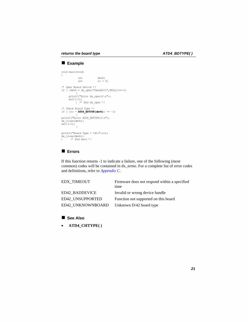
Example
void main(void) { int devh; int rc = 0; /* Open Board Device */ if ( (devh = dx_open("dxxxB1C1",NULL))==-1)
{ printf("Error dx_open()\n"); exit(-1); } /* End dx_open */
/* Check Board Type */ if ( (rc = ATD4_BDTYPE(devh)) == -1) { printf("Error ATD4_BDTYPE()\n"); dx_close(devh); exit(-1); } printf("Board Type = %d\n",rc); dx_close(devh); } /* End main */
Errors
If this function returns -1 to indicate a failure, one of the following (most common) codes will be contained in dx_errno. For a complete list of error codes and definitions, refer to Appendix C. EDX_TIMEOUT Firmware does not respond within a specified
time ED42_BADDEVICE Invalid or wrong device handle ED42_UNSUPPORTED Function not supported on this board ED42_UNKNOWNBOARD Unknown D/42 board type
See Also
• ATD4_CHTYPE( )
21

ATD4_CHTYPE( ) returns the channel type
int ATD4_CHTYPE(devh) Name:Inputs: int devh • channel descriptor
Returns: channel type • returned channel type information (see below) 0 • if success -1 • if error; see Errors below. D42LIB.H Includes:synchronous Mode:
Description
The ATD4_CHTYPE( ) function returns the channel type of the queried device.
Channel Type Description
TYP_D82L4 Avaya Definity 75 TYP_D82L2 Avaya Definity G3 TYP_D82SX MITEL SX Series TYP_D82NE2PBX NEC NEAX 2000 IVS, IVS2, IPS
NEC NEAX 2400 IMS TYP_D82NE2KTS NEC Electra Elite, NEC Electra Professional 120 TYP_D82BCM Nortel BCM1000, BCM400, BCM200, and BCM50 TYP_D82NS Nortel Norstar DR5, CICS and MICS TYP_D82M1 Nortel Meridian 1 TYP_D82SR Siemens ROLM CBX 9005, 9006 and 9715 TYP_D82SH Siemens Hicom 150 and 300
Parameter Description
devh specifies the valid channel device descriptor obtained by a call to dx_open( )
Cautions
None.
22

returns the channel type ATD4_CHTYPE( )
Example
void main(void) { int devh; int rc = 0; /* Open Channel Device */ if ( (devh = dx_open("dxxxB1C1",NULL))==-1)
{ printf("Error dx_open()\n"); exit(-1); } /* End dx_open */
/* Check Channel Type */ if ( (rc = ATD4_CHTYPE(devh))== -1) { printf("Error ATD4_CHTYPE()\n"); dx_close(devh); exit(-1); } printf("Channel Type = %d\n",rc); dx_close(devh); } /* End main */
Errors
If this function returns -1 to indicate a failure, one of the following (most common) codes will be contained in dx_errno. For a complete list of error codes and definitions, refer to Appendix C. EDX_TIMEOUT Firmware does not respond within a specified
time ED42_BADDEVICE Invalid or wrong device handle ED42_UNSUPPORTED Function not supported on this board ED42_UNKNOWNBOARD Unknown D/42-xx or PBX Integration Board
type
See Also
• ATD4_BDTYPE( )
23

d42_brdstatus( ) retrieves the current board status
int d42_brdstatus(devh, buffstatus, bufferp) Name: Inputs: int devh • board descriptor
char *buffstatus • pointer to buffer containing board status information
char *bufferp • reserved for future use Returns: 0 • if success
-1 • if error; see Errors below. D42LIB.H Includes: synchronous Mode:
Description
The d42_brdstatus( ) function retrieves the current board status and places it in an application buffer. The board status is a bit mask representing the status of the board (see below) on a per board basis. Each Dialogic® D/82JCT-U Board contains two virtual boards of four channels each, for a total of eight channels. Each Dialogic® D/42JCT-U Board contains one virtual board of four channels. The application buffer (buffstatus) that will contain the board status information must be one byte.
Bit 7 6 5 4 3 2 1 0Channel x x x x 4 3 2 1Example* 0 0 0 0 1 1 1 1* Data shows that all channels on the board have communication.
bit0 first channel on board 1=OK, 0=no communication bit1 second channel on board 1=OK, 0=no communication bit2 third channel on board 1=OK, 0=no communication bit3 fourth channel on board 1=OK, 0=no communication Parameter Description
devh specifies the valid board device descriptor obtained by a call to dx_open( )
buffstatus pointer to the 1-byte application buffer where the board status is placed
bufferp pointer to an additional application buffer (reserved for future use)
24

retrieves the current board status d42_brdstatus( )
Cautions
The character pointer bufferp is required. The associated buffer must be 49 bytes.
Example
void main(void) { int devh; int rc = 0; char buffstatus; char bufferp[49]; /* Open Channel Device */ if ( (devh = dx_open("dxxxB1C1",NULL))==-1) { printf("Error dx_open()\n"); exit(-1); } /* End dx_open */ /* Get the board status Information */ if ( (rc = d42_brdstatus(devh, &buffstatus, bufferp)) == -1) { printf("Error d42_brdstatus()\n"); dx_close(devh); exit(-1); } /* End d42_brdstatus*/ printf("Board Status = %X\n",buffstatus); dx_close(devh); } /* End main */
Errors
If this function returns -1 to indicate a failure, one of the following (most common) codes will be contained in dx_errno. For a complete list of error codes and definitions, refer to Appendix C. ED42_BADDEVICE Invalid or wrong device handle ED42_UNSUPPORTED Function not supported on this board ED42_SYSTEM System level error ED42_INVALARG Invalid argument passed to function
See Also
• d42_chnstatus( )
25

d42_chnstatus( ) retrieves the current channel status
int d42_chnstatus(devh, statusp, bufferp) Name: Inputs: int devh • channel descriptor
char *statusp • pointer to buffer containing channel status information
char *bufferp • reserved for future use Returns: 0 • if success
-1 • if error; see Errors below. D42LIB.H Includes: synchronous Mode:
Description
The d42_chnstatus( ) function retrieves the current channel status and places it in an application buffer. The application buffer (statusp) that will contain the channel status information must be one byte. The channel status is a single bit (bit 0) representing the status of the channel device.
Parameter Description
devh specifies the valid channel device descriptor obtained by a call to dx_open( )
statusp pointer to a 1-byte application buffer. The application buffer will contain a non-zero value if the channel is communicating with the switch. • non-zero = OK • 0 = no communications
bufferp pointer to an additional application buffer (reserved for future use)
Cautions
The character pointer bufferp is required. The associated buffer must be 49 bytes.
Example
void main(void) { int devh; int rc = 0;
char bufferp[49];
26

retrieves the current channel status d42_chnstatus( )
char status; /* Open Channel Device */ if ( (devh = dx_open("dxxxB1C1",NULL))==-1) { printf("Error dx_open()\n"); exit(-1); } /* End dx_open */ /* Get the channel status Information */ if ( (rc = d42_chnstatus(devh, &statusp, bufferp)) == -1) { printf("Error d42_chnstatus():\n"); dx_close(devh); exit(-1); } /* End d42_chnstatus*/ if (status) { printf("Channel Communication OK\n"); } else { printf("No Channel Communication\n"); } dx_close(devh); } /* End main */
Errors
If this function returns -1 to indicate a failure, one of the following (most common) codes will be contained in dx_errno. For a complete list of error codes and definitions, refer to Appendix C. ED42_BADDEVICE Invalid or wrong device handle ED42_UNSUPPORTED Function not supported on this board ED42_SYSTEM System level error ED42_INVALARG Invalid argument passed to function
See Also
• d42_brdstatus( )
27
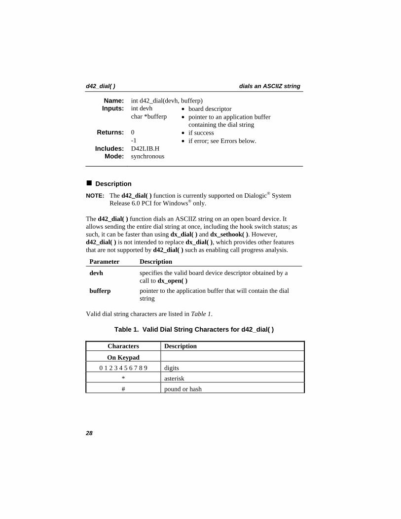
d42_dial( ) dials an ASCIIZ string
int d42_dial(devh, bufferp) Name: Inputs: int devh • board descriptor
char *bufferp • pointer to an application buffer containing the dial string
Returns: 0 • if success -1 • if error; see Errors below.
D42LIB.H Includes: synchronous Mode:
Description
NOTE: The d42_dial( ) function is currently supported on Dialogic® System Release 6.0 PCI for Windows® only.
The d42_dial( ) function dials an ASCIIZ string on an open board device. It allows sending the entire dial string at once, including the hook switch status; as such, it can be faster than using dx_dial( ) and dx_sethook( ). However, d42_dial( ) is not intended to replace dx_dial( ), which provides other features that are not supported by d42_dial( ) such as enabling call progress analysis.
Parameter Description
devh specifies the valid board device descriptor obtained by a call to dx_open( )
bufferp pointer to the application buffer that will contain the dial string
Valid dial string characters are listed in Table 1.
Table 1. Valid Dial String Characters for d42_dial( )
Characters Description
On Keypad 0 1 2 3 4 5 6 7 8 9 digits
* asterisk # pound or hash
28

dials an ASCIIZ string d42_dial( )
Characters Description
Special Control ^ off-hook | on-hook
0x1b <ESC>
The following guidelines apply to the use of bufferp, which contains the dial string to be dialed:
• The symbol “^” instructs the board to go off-hook. This must be matched with the symbol “|”, at the end of the call; the application should not terminate the call with dx_sethook( ). Once the call is terminated, subsequent calls may use dx_sethook( ) and dx_dial( ), or continue using d42_dial( ) to initiate and terminate calls.
• There can only be zero or one <ESC> dial sequence in the dial string. An <ESC> sequence is defined to be “<ESC>K<X>”, where <X> is PBX-specific. Consult the Dialogic PBX Integration Board User’s Guide® .
• All characters not shown in the above table are ignored.
• Bufferp must be NULL terminated.
Once a call is connected, the application may use dx_dial( ).
Cautions
The application buffer cannot exceed 48 bytes, including the NULL terminator.
Example
#include <stdio.h> #include “d42lib.h” #include “dxxxlib.h”
#define ESC 0x1B void main(void) { int devh; int rc = 0; char bufferp[D42_MAXDIALSTRING];
/* Initialize the dial string for a Nortel Meridian PBX */ // parenthesis and dashes are ignored/thrown away sprintf(bufferp, “%cKA^91-800-(555)-1234”, ESC);
29

d42_dial( ) dials an ASCIIZ string
/* Open Board Device */ if ( (devh = dx_open("dxxxB1C1", NULL))==-1) { printf("Error dx_open()\n"); exit(-1); } /* End dx_open */
/* connect */ if ( (rc = d42_dial(devh, bufferp)) == -1) { printf("Error d42_dial() - connecting\n"); dx_close(devh); exit(-1); } /* End d42_dial */
/* connected! */ . . .
/* disconnect */ strcpy(bufferp, “|”); if ( (rc = d42_dial(devh, bufferp)) == -1) { printf("Error d42_dial() - disconnect\n"); dx_close(devh); exit(-1); } /* End d42_dial */
dx_close(devh); } /* End main */
Errors
If this function returns -1 to indicate a failure, one of the following (most common) codes will be contained in dx_errno. For a complete list of error codes and definitions, refer to Appendix C. ED42_BADDEVICE Invalid or wrong device handle ED42_BADPARM String is too long ED42_INVALARG Invalid argument passed to function. Dial string is
NULL. ED42_FWREQFAILURE Firmware failure to either receive or complete the
request
30

retrieves the current LCD/LED display d42_display( )
int d42_display(devh, bufferp) Name: Inputs: int devh • channel descriptor
char *bufferp • pointer to an application buffer. The buffer will contain display data for the selected channel.
Returns: 0 • if success -1 • if error; see Errors below.
D42LIB.H Includes: synchronous Mode:
Description
The d42_display( ) function retrieves the current LCD/LED display (alphanumeric) data and places it in an application buffer. The application buffer must be 49 bytes, and will hold an entire data string up to 48 bytes (see below) plus a null. The length of the data string is 32 or 48 bytes for the supported PBXs. Byte 0 of the display data corresponds to the top, left-most display element. The display data is stored as a null-terminated ASCII string. Refer to the Dialogic PBX Integration Board User’s Guide
®
for more information specific to supported PBXs. Examples showing the contents of the application buffer for each supported switch with a display less than or equal to 48 bytes are shown below:
Siemens Hicom - 48-digit display
data 4E 6F 65 6C 20 4D 63 4C 6F 75 67 68 6C 69 6E 20
0 1 2 3 4 5 6 7 8 9 10 11 12 13 14 15 byte
data 20 20 20 20 20 20 20 20 43 6F 6E 73 75 6C 74 61 16 17 18 19 20 21 22 23 24 25 26 27 28 29 30 31 byte
data 74 69 6F 6E 3F 20 20 20 20 20 20 20 20 20 20 20
32 33 34 35 36 37 38 39 40 41 42 43 44 45 46 47 byte
31

d42_display( ) retrieves the current LCD/LED display
MITEL SUPERSET 420 - 32-character display
data 43 41 4C 4C 46 4F 52 44 57 41 52 49 4E 47 3F 20
0 1 2 3 4 5 6 7 8 9 10 11 12 13 14 15 byte
data 59 65 73 20 20 20 20 20 20 20 20 20 20 4E 6F 20 16 17 18 19 20 21 22 23 24 25 26 27 28 29 30 31 byte
xx xx xx xx xx xx xx xx xx xx xx xx xx xx xx xx data 32 33 34 35 36 37 38 39 40 41 42 43 44 45 46 47 byte
Nortel Norstar and Nortel BCM - 32-character display
data 54 72 61 6E 73 66 65 72 20 20 20 20 20 20 20 20
0 1 2 3 4 5 6 7 8 9 10 11 12 13 14 15 byte
data 20 20 20 20 20 20 20 20 20 20 20 20 20 20 20 20 16 17 18 19 20 21 22 23 24 25 26 27 28 29 30 31 byte
xx xx xx xx xx xx xx xx xx xx xx xx xx xx xx xx data 32 33 34 35 36 37 38 39 40 41 42 43 44 45 46 47 byte
Nortel Meridian 1 - 48-character display
data 61 32 01 00 04 05 20 20 20 20 20 20 20 20 20 20
0 1 2 3 4 5 6 7 8 9 10 11 12 13 14 15 byte
data 20 20 20 20 20 20 20 20 20 20 20 20 20 20 20 20 16 17 18 19 20 21 22 23 24 25 26 27 28 29 30 31 byte
data 20 20 20 20 20 20 20 20 20 20 20 20 20 20 20 20
32 33 34 35 36 37 38 39 40 41 42 43 44 45 46 47 byte
32

retrieves the current LCD/LED display d42_display( )
Parameter Description
devh specifies the valid channel device descriptor obtained by a call to dx_open( )
bufferp pointer to the application buffer. The buffer will contain the display data in ASCII format.
Cautions
• The application buffer must be 49 bytes. The length of the LCD display data is 48 bytes for the supported PBXs listed above. All other supported PBXs have longer-length LCD display data, so d42_displayex( ) must be used. The data is stored as a null-terminated ASCII string. An application that passes anything smaller will not be backward compatible.
• If you execute a function that updates the display (e.g., set the message waiting indicator, or show the calling number ID), make sure that you allow time for the switch to update the display before using d42_display( ), or you can call the d42_display( ) function until valid display data is returned.
Example
void main(void) { int devh; int rc = 0; char bufferp[49]; /* Open Channel Device */ if ( (devh = dx_open("dxxxB1C1",NULL))==-1) { printf("Error dx_open()\n"); exit(-1); } /* End dx_open */ /* Wait for incoming call */ if ( (rc = dx_wtring(devh, 2, DX_ONHOOK, -1))==-1) { printf("Error dx_wtring()\n"); dx_close(devh); exit(-1); } /* Get the Display Information */ if ( (rc = d42_display(devh, bufferp)) == -1) { printf("Error d42_display()\n"); dx_close(devh); exit(-1); } /* End d42_display */ printf("Display = %s\n",bufferp);
33

d42_display( ) retrieves the current LCD/LED display
dx_close(devh); } /* End main */
Errors
If this function returns -1 to indicate a failure, one of the following (most common) codes will be contained in dx_errno. For a complete list of error codes and definitions, refer to Appendix C. ED42_BADDEVICE Invalid or wrong device handle ED42_UNSUPPORTED Function not supported on this board ED42_SYSTEM System level error ED42_INVALARG Invalid argument passed to function
See Also
• d42_displayex( )
34

retrieves the current LCD/LED display d42_displayex( )
int d42_displayex(devh, bufferp, buflen) Name: Inputs: int devh • channel descriptor
char *bufferp • pointer to an application buffer. The buffer will contain display data for the selected channel.
buflen • length of buffer Returns: 0
-1 • if success • if error; see Errors below.
D42LIB.H Includes: synchronous Mode:
Description
The d42_displayex( ) function retrieves the current LCD/LED display (alphanumeric) data and places it in an application buffer. Unlike d42_display( ), this function can retrieve display data larger than 49 bytes. The buffer must be at least 49 bytes, which would mean a data string of 48 bytes plus a null. The length of the data string is 50 for the Avaya Definity G3 and 75 PBXs; 60 for the Siemens ROLM CBX 9005, 9006 and 9715; and 80 for the MITEL SX-200 and SX-2000 PBXs. Byte 0 of the display data corresponds to the top, left-most display element. The display data is stored as a null-terminated ASCII string. Refer to the Dialogic PBX Integration Board User’s Guide® for more information specific to supported PBXs. An example showing the contents of the application buffer for each supported switch with a display larger than 48 bytes is shown below. d42_displayex( ) may also be used for display sizes smaller than 48 bytes.
Avaya Definity - 50-character display
data 20 20 20 20 20 20 20 20 20 20 20 20 20 20 20 20 20 20 20 20 20 20 20 20
20byte 0 1 2 3 4 5 6 7 8 9 10 11 12 13 14 15 16 17 18 19 20 21 22 23
24
data 52 45 4C 45 41 53 45 20 41 4E 44 20 54 52 59 20 41 47 41 49 4E 20 20 20
20byte 25 26 27 28 29 30 31 32 33 34 35 36 37 38 39 40 41 42 43 44 45 46 47 48
49
35

d42_displayex( ) retrieves the current LCD/LED display
Siemens ROLM - 60-character display
data 43 4F 4E 46 45 52 45 4E 43 45 20 20 20 20 20 20 01 02 03 20byte 00 01 02 03 04 05 06 07 08 09 10 11 12 13 14 15 16 17 18 19
data 20 20 20 20 20 20 20 20 20 20 59 4F 55 52 20 50 4F 53 49 54byte 20 21 22 23 24 25 26 27 28 29 30 31 32 33 34 35 36 37 38 39
data 49 4F 4E 3A 20 20 01 20 20 20 20 20 20 20 20 20 20 20 20 20byte 40 41 42 43 44 45 46 47 48 49 50 51 52 53 54 55 56 57 58 59
MITEL SUPERSET 430 - 80-character display
data 01 00 00 01 20 41 43 55 52 52 41 4E 20 49 53 20 43 41 4C 4C byte 00 01 02 03 04 05 06 07 08 09 10 11 12 13 14 15 16 17 18 19
data 49 4E 47 20 20 20 20 20 20 20 20 20 20 20 20 20 20 20 20 20 byte 20 21 22 23 24 25 26 27 28 29 30 31 32 33 34 35 36 37 38 39
data 20 20 20 20 20 20 20 20 20 20 20 20 20 20 20 20 20 20 20 20byte 40 41 42 43 44 45 46 47 48 49 50 51 52 53 54 55 56 57 58 59
data 20 20 20 20 20 20 20 20 20 20 20 20 20 20 20 20 20 20 20 20byte 60 61 62 63 64 65 66 67 68 69 70 71 72 73 74 75 76 77 78 79
Parameter Description
devh specifies the valid channel device descriptor obtained by a call to dx_open( )
bufferp pointer to the application buffer. The buffer will contain the display data in ASCII format.
buflen length of buffer on entry
36

retrieves the current LCD/LED display d42_displayex( )
Cautions
• The pointer to the application buffer is assumed to be large enough to hold the entire string plus a null, and the total must be at least 49 bytes.
• If you execute a function that updates the display (e.g., set the message waiting indicator, or show the calling number ID), make sure that you allow time for the switch to update the display before using d42_displayex( ), or you can call the d42_displayex( ) function until valid display data is returned.
Example
void main(void) { int devh; int buflen = 50; int rc = 0; char bufferp[50]; /* Open Channel Device */ if ( (devh = dx_open("dxxxB1C1",NULL))==-1) { printf("Error dx_open()\n"); exit(-1); } /* End dx_open */ /* Wait for incoming call */ if ( (rc = dx_wtring(devh, 2, DX_ONHOOK, -1))==-1) { printf("Error dx_wtring()\n"); dx_close(devh); exit(-1); } /* Get the Display Information */ if ( (rc = d42_displayex(devh, bufferp, buflen)) == -1) { printf("Error d42_displayex()\n"); dx_close(devh); exit(-1); } /* End d42_displayex */ printf("Display = %s\n",bufferp); dx_close(devh); } /* End main */
Errors
If this function returns -1 to indicate a failure, one of the following (most common) codes will be contained in dx_errno. For a complete list of error codes and definitions, refer to Appendix C.
37

d42_displayex( ) retrieves the current LCD/LED display
ED42_BADDEVICE Invalid or wrong device handle ED42_UNSUPPORTED Function not supported on this board ED42_SYSTEM System level error ED42_INVALARG Invalid argument passed to function ED42_MEMORY Buffer not large enough
See Also
• d42_display( )
38
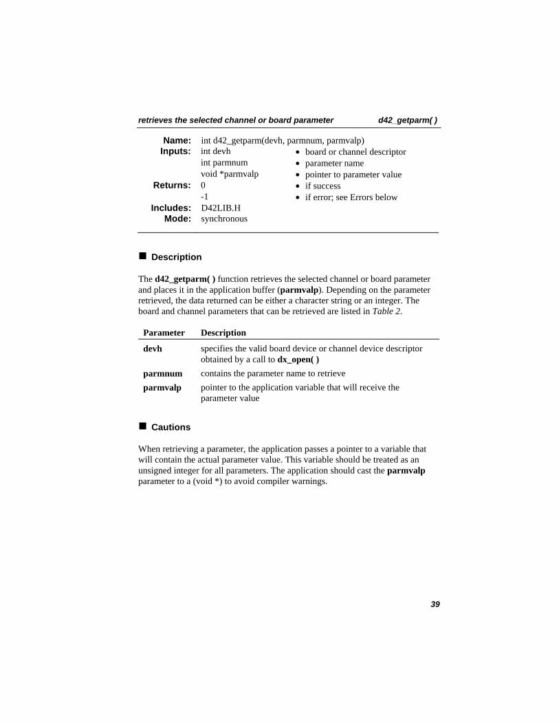
retrieves the selected channel or board parameter d42_getparm( )
int d42_getparm(devh, parmnum, parmvalp) Name: Inputs: int devh • board or channel descriptor
int parmnum • parameter name void *parmvalp • pointer to parameter value
Returns: 0 • if success -1 • if error; see Errors below
D42LIB.H Includes: synchronous Mode:
Description
The d42_getparm( ) function retrieves the selected channel or board parameter and places it in the application buffer (parmvalp). Depending on the parameter retrieved, the data returned can be either a character string or an integer. The board and channel parameters that can be retrieved are listed in Table 2.
Parameter Description
devh specifies the valid board device or channel device descriptor obtained by a call to dx_open( )
parmnum contains the parameter name to retrieve parmvalp pointer to the application variable that will receive the
parameter value
Cautions
When retrieving a parameter, the application passes a pointer to a variable that will contain the actual parameter value. This variable should be treated as an unsigned integer for all parameters. The application should cast the parmvalp parameter to a (void *) to avoid compiler warnings.
39

d42_getparm( ) retrieves the selected channel or board parameter
Table 2. Board and Channel Parameters for d42_getparm( )
Board Parameters Description
D4BD_CALLID Enables caller ID. Values: 0 - disable (default) 1 - enable
D4BD_GETSWITCHTYPE Obtains the switch type. Values:
PBX_L4 PBX_L2 PBX_SH PBX_SR PBX_BCM PBX_NS PBX_M1 PBX_SX PBX_SX2
- Avaya 75 - Avaya G3 - Siemens Hicom 150 and 300 - Siemens ROLM CBX 9005, 9006, or 9715 - Nortel BCM 1000, 400, 200, 50 - Norstar DR5, CICS, or MICS - Meridian 1 - MITEL SX-50 - MITEL SX-200 or SX-2000
D4BD_M1_DISPLAYWIDTH Sets the display width for Nortel M1 integration. Values: 0 - 2x24 size display (default) 1 - 2x33 size display
NOTE: When using 2x33 size displays, d42_display( ) will not return the entire display, d42_displayex( ) must be used.
D4CH_CHANNELSTATUS Receives asynchronous channel status messages. Values: 0 - disable (default) 1 - enable
D4CH_LC_LAMP Lamp to monitor for loop current.
40

retrieves the selected channel or board parameter d42_getparm( )
Board Parameters Description
D4CH_CHANNELUPDATE Enables/disables asynchronous LCD and indicator updates.
Example
#include "srllib.h" #include "d42lib.h" #include "dxxxlib.h"
static char * pbxnames[] = { "None", "None01", "None02", "None03", "None04", "None05", "None06", "None07", "None08", "None09", "PBX Lucent 4-wire", // 0x0A "PBX Lucent 2 wire", // 0x0B "PBX Nortel Norstar", // 0x0C "PBX Nortel M1", // 0x0D "PBX Seimens Rolm", // 0x0E "PBX Seimens Hicom", // 0x0F "PBX Mitel", // 0x10 "PBX Mitel 2k", // 0x11 "PBX NE2K", // 0x12 "PBX NE2P", // 0x13 "Empty0x14", // 0x14 "PBX Nortel BCM" // 0x15 };
int main(void) { int devh; int rc = 0; unsigned int parmvalp = 0;
/* Open Board Device */ if ( (devh = dx_open("dxxxB1", NULL)) == -1) { printf("Error dx_open()\n"); exit(-1); } /* END dx_open */
/* get the PBX type */ if ( (rc = d42_getparm(devh, D4BD_GETSWITCHTYPE, &parmvalp)) == -1) { printf("Error d42_getparm()\n"); dx_close(devh); exit(-1); } /* END d42_getparm */
41

d42_getparm( ) retrieves the selected channel or board parameter
/* show the results */ printf( "PBX is (0x%x) %s\n", parmvalp, pbxnames[parmvalp]);
dx_close(devh);
} /* END main */
Errors
If this function returns -1 to indicate a failure, one of the following (most common) codes will be contained in dx_errno. For a complete list of error codes and definitions, refer to Appendix C. ED42_BADDEVICE Invalid or wrong device handle ED42_UNSUPPORTED Function not supported on this board ED42_SYSTEM System level error ED42_INVALARG Invalid argument passed to function
See Also
• d42_setparm( )
42

retrieves the board firmware or library version d42_getver( )
int d42_getver(devh, bufferp, flag) Name: Inputs: int devh • board descriptor
char *bufferp • pointer to an application buffer containing the version information
int flag • determines if firmware or library version is retrieved
Returns: 0 • if success -1 • if error; see Errors below.
D42LIB.H Includes: synchronous Mode:
Description
The d42_getver( ) function retrieves the board firmware or library version and places it in an application buffer. The application buffer is at least 100 bytes long and will contain either the firmware or library version number in the following format:
Firmware Firmware Version: XX.XX type YY.YY
where: XX.XX is the version number type is the type of release (Alpha, Beta, Experimental, or Production) YY.YY is the alpha or experimental number
Library File Version: YY.MM.XX.XX Product Version: YY.MM.XX.XX
where: YY is the year MM is the month X is a number
43

d42_getver( ) retrieves the board firmware or library version
Parameter Description
devh specifies the valid board device descriptor obtained by a call to dx_open( )
bufferp pointer to the application buffer that will contain the version data flag determines if the firmware or library version number is placed in
the application buffer • VER_D42FIRMWARE - returns the D/42-xx or PBX
Integration Board firmware version • VER_D42LIB - returns the D42 library (D42LIB) version
Cautions
The application buffer must be at least 100 bytes.
Example
void main(void) { int devh; int rc = 0; char bufferp[100]; /* Open Board Device */ if ( (devh = dx_open("dxxxB1",NULL))==-1) { printf("Error dx_open()\n"); exit(-1); } /* End dx_open */ /* Get the Firmware Version */ if ( (rc = d42_getver(devh, bufferp, VER_D42FIRMWARE)) == -1) { printf("Error d42_getver()\n"); dx_close(devh); exit(-1); } /* End d42_getver */ /* Print the Firmware Version /* printf("%s",bufferp); dx_close(devh); } /* End main */
Errors
If this function returns -1 to indicate a failure, one of the following (most common) codes will be contained in dx_errno. For a complete list of error codes and definitions, refer to Appendix C.
44

retrieves the board firmware or library version d42_getver( )
ED42_BADDEVICE Invalid or wrong device handle ED42_UNSUPPORTED Function not supported on this board ED42_SYSTEM System level error ED42_RDFWVER Error reading firmware version ED42_INVALARG Invalid argument passed to function
45
d42_gtcallid( ) retrieves the called/calling number ID
int d42_gtcallid(devh, bufferp) Name:Inputs: int devh • channel descriptor
char *bufferp • pointer to an application buffer containing called/calling number ID data
Returns: 0 • if success -1 • if error; see Errors below D42LIB.H Includes:synchronous Mode:
Description
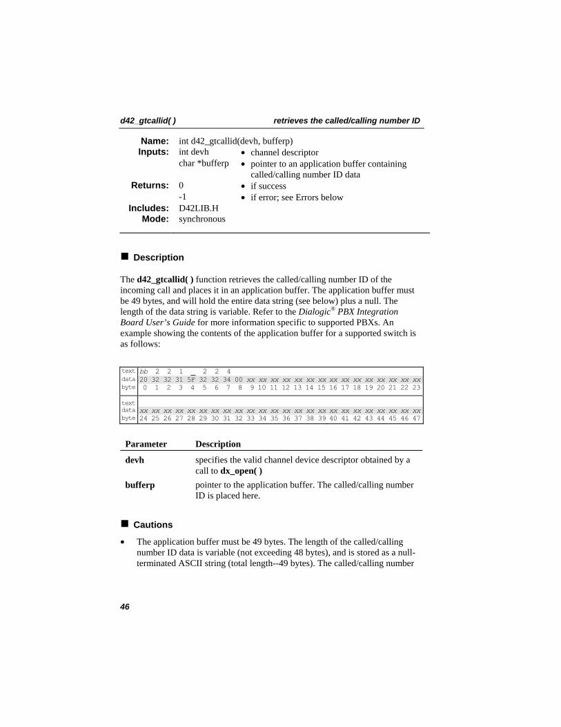
The d42_gtcallid( ) function retrieves the called/calling number ID of the incoming call and places it in an application buffer. The application buffer must be 49 bytes, and will hold the entire data string (see below) plus a null. The length of the data string is variable. Refer to the Dialogic PBX Integration Board User’s Guide
®
for more information specific to supported PBXs. An example showing the contents of the application buffer for a supported switch is as follows:
text bb 2 2 1 _ 2 2 4 data 20 32 32 31 5F 32 32 34 00 xx xx xx xx xx xx xx xx xx xx xx xx xx xx xxbyte 0 1 2 3 4 5 6 7 8 9 10 11 12 13 14 15 16 17 18 19 20 21 22 23
text data xx xx xx xx xx xx xx xx xx xx xx xx xx xx xx xx xx xx xx xx xx xx xx xx byte 24 25 26 27 28 29 30 31 32 33 34 35 36 37 38 39 40 41 42 43 44 45 46 47
Parameter Description
devh specifies the valid channel device descriptor obtained by a call to dx_open( )
bufferp pointer to the application buffer. The called/calling number ID is placed here.
Cautions
• The application buffer must be 49 bytes. The length of the called/calling number ID data is variable (not exceeding 48 bytes), and is stored as a null-terminated ASCII string (total length--49 bytes). The called/calling number
46

retrieves the called/calling number ID d42_gtcallid( )
cannot contain spaces; the information will only be parsed up to the first space.
• For Avaya 7434 (4-wire) and 8434 (2-wire) telephone sets, the extension number must be programmed in the first 16 characters of the PBX name field.
NOTE: Since the called/calling number ID data is not always sent by the PBX prior to the ring event, the application should be set up to answer a call only after the second ring so that the correct called/calling ID data can be obtained.
Example
void main(void) { int devh; int rc = 0; char bufferp[49]; /* Open Channel Device */ if ( (devh = dx_open("dxxxB1C1",NULL))==-1) { printf("Error dx_open()\n"); exit(-1); } /* End dx_open */ /* Wait for incoming call */ if ( (rc = dx_wtring(devh, 2, DX_ONHOOK, -1))==-1) { printf("Error dx_wtring()\n"); dx_close(devh); exit(-1); } /* Get the Calling/Caller Id */ if ( (rc = d42_gtcallid(devh, bufferp)) == -1) { printf("Error d42_gtcallid()\n"); dx_close(devh); exit(-1); } /* End d42_gtcallid */ printf("Caller Id = %s\n",bufferp); dx_close(devh); } /* End main */
Errors
If this function returns -1 to indicate a failure, one of the following (most common) codes will be contained in dx_errno. For a complete list of error codes and definitions, refer to Appendix C.
47

d42_gtcallid( ) retrieves the called/calling number ID
ED42_BADDEVICE Invalid or wrong device handle ED42_UNSUPPORTED Function not supported on this board ED42_SYSTEM System level error ED42_INVALARG Invalid argument passed to function
48

retrieves call information d42_gtcallidex( )
int d42_gtcallidex(devh, *pcallidex) Name: Inputs: int devh • channel descriptor
Outputs: CALLIDEX *pcallidex • pointer to a CALLIDEX structure containing the call information
Returns: 0 -1
• if success • if error; see Errors below
d42lib.h Includes: synchronous Mode:
Description
The d42_gtcallidex( ) function retrieves call information, such as the type of call (internal or external), the reason for the call (direct, forwarded as a result of being busy, forwarded because of no answer, etc.), with calling party ID and called party ID.
NOTE: For Nortel Norstar and BCM PBXs, all information, including the reason code and call type integration, is available. For other integrations, the reason code and call type are not available, but the calling ID (calling_id) and called ID (called_id) are available.
Parameter Description
devh specifies a valid channel device descriptor *pcallidex pointer to a CALLIDEX structure that contains the call
information
Structure and Constant Definitions
The following definitions define the call type:
#define CALL_TYP_NULL 0x00 // None #define CALL_TYP_INTERNAL 0X01 // internal call #define CALL_TYP_EXTERNAL 0x02 // external call
The following definitions are the possible reason codes that could be returned:
#define RSN_NULL 0x00 // None #define RSN_DIRECT 0X01 // Direct call #define RSN_FBUSY 0x02 // Call forwarded because busy #define RSN_FNOANS 0X03 // Call forwarded because of no answer #define RSN_SPR_XFR 0x04 // Supervised call transfer #define RSN_UNSPR_XFR 0x05 // Unsupervised call transfer
49

d42_gtcallidex( ) retrieves call information
#define RSN_FALL 0x06 // call Forwarded always #define RSN_TIME 0x07 // display contains time info only (no CPID) #define RSN_GENERIC_FWD 0x08 // generic Forwarded call
NOTES: 1. The first two reason codes above are not used.
2. The last reason code is returned only by the BCM. In addition, the BCM does not return the reason codes of RSN_FBUSY, RSN_FNOANS, or RSN_FALL.
The CALLIDEX structure is defined as follows:
typedef struct tagCALLIDEX { char called_id[CALLID_LEN]; char calling_id[CALLID_LEN]; int call_type; int reason_code; }CALLIDEX;
Cautions
It is the application’s responsibility to allocate memory for the pointer pcallidex of size CALLIDEX.
Example
CALLIDEX callidex; ... // open device ... // pass device handle to d42_gtcallidex() rc = d42_gtcallidex(devh, &callidex); if(rc < 0) { // handle the error here } ...
Errors
If this function returns -1 to indicate a failure, the ATDV_LASTERR( ) function can be used to retrieve the reason for the error. The error codes that can be returned are as follows:
ED42_BADDEVICE Invalid or wrong device handle
50

retrieves call information d42_gtcallidex( )
ED42_INVALARG Invalid argument passed to function ED42_UNKNOWNBOARD The board is not supported ED42_FWREQFAILURE Firmware request failed
See Also
• d42_gtcallid( )
51

d42_indicators( ) retrieves the current LCD or LED indicators
int d42_indicators(devh, bufferp) Name: Inputs: int devh • channel descriptor
char *bufferp • pointer to an application buffer containing the indicators data
Returns: 0 • if success -1 • if error; see Errors below
D42LIB.H Includes: synchronous Mode:
Description
The d42_indicators( ) function retrieves the current LCD or LED indicators status and places it in an application buffer. The application buffer must be 49 bytes, and will hold the entire bit mask (see below) representing the status of each indicator. Refer to the Dialogic PBX Integration Board User’s Guide® for more information specific to supported switches. Examples showing the contents of the application buffer for each supported switch are as follows:
PBX Number of Indicators Avaya 7434 4-wire 41 indicators Avaya 8434 2-wire 34 indicators Siemens/ROLM 36 indicators Siemens Hicom 12 indicators MITEL SUPERSET 400 12 indicators Nortel Norstar M7324 24 indicators Nortel BCM M7324 24 indicators Nortel Meridian 1 M2616 16 indicators
Parameter Description
devh specifies the valid channel device descriptor obtained by a call to dx_open( )
bufferp pointer to the application buffer; the indicator is placed here
Cautions
The application buffer must be 49 bytes. The length of the line indicator data is variable (currently 126-34 bytes), and is stored as bit mask. An application that passes anything smaller will not be compatible.
52
retrieves the current LCD or LED indicators d42_indicators( )
Avaya 7434 (4-Wire) and Avaya 8434 (2-Wire)
On the Avaya 7434 telephone, there are a total of 34 sets of line indicators (a set of two indicators, with red on the left and green on the right). Twelve LED line indicators are located to the left of line keys 00-23. In addition, there are 10 LED line indicators located to the left of line keys 24-33 (see Figure 1).
Like the 7434, the Avaya 8434 also has a total of 34 sets of line indicators (a set of two indicators, with red on the top and green on the bottom), but their arrangement is somewhat different (see Figure 2). Twelve LED line indicators are located to the left of line keys 00-11, and 12 LED line indicators are located to the right of keys 12-23 on the Avaya 8434 telephone. In addition, there are five LED line indicators located to the left of line keys 24-28, and five LED line indicators located to the right of line keys 29-33.
For both phones, the indicator status data stored in the application buffer is 34 bytes long. Bytes 0-33 contain the indicator status of Feature Buttons 0-33, respectively.
As mentioned above, each line or feature button actually has two indicator lights. The red indicator tells the user that the line is being used or that the line will be the one used when the handset is lifted. The green indicator (bottom on the 8434 and right on the 7434) tells the user that the line or feature is in use. In other words, when a user picks up the handset or presses a feature button, the green indicator goes on.
When a call is on hold, the green indicator for that line flashes and the red indicator goes off. The red light is either off or on (a value of eight [0x08] indicates ON), while the green light has six possible values.
53

d42_indicators( ) retrieves the current LCD or LED indicators
The status of the indicators is obtained by bitwise-ANDing the returned value from the green light with the value from the red light (green light value + red light value). In other words, the value for a line indicator in use with a call would be nine--0x08 (for red light on) + 0x01 (for green light on). The status conditions for each byte of the green light are defined as follows:
Value (in HEX) State
0x00 off 0x01 on 0x02 ringing 0x03 hold 0x04 error 0x05 unknown
Example
If the data for byte 19 is 0x09 and byte 28 is 0x03, the red and green indicators are on for Feature Button 19, indicating that the line is in use for a call, and the green indicator for Memory Button 28 is flashing, indicating that the call is on hold. The contents of the application buffer are shown below.
24 25 26 27 28 29 30 31 32 33 34 35 36 37 38 39 40 41 42 43 44 45 46 47
16 17 18 19 20 21 22 23Data
Data
Byte
Byte
00 00 00 00 00 00 00 00 00 0000 01 02 03 04 05 06 07 08 09 10 11 12 13 14 15
Feat
ure
But
ton
00
But
ton
01
But
ton
02
But
ton
03
But
ton
04
But
ton
05
But
ton
06
But
ton
07
But
ton
08
But
ton
09
Feat
ure
Feat
ure
Feat
ure
Feat
ure
Feat
ure
Feat
ure
Feat
ure
Feat
ure
Feat
ure
Feat
ure
Feat
ure
Feat
ure
Feat
ure
Feat
ure
Feat
ure
Feat
ure
Feat
ure
Feat
ure
Feat
ure
Feat
ure
Feat
ure
Feat
ure
Feat
ure B
utto
n 10
But
ton
11
But
ton
12
But
ton
13
But
ton
14
But
ton
15
But
ton
16
But
ton
17
But
ton
18
But
ton
19
But
ton
20
But
ton
21
But
ton
22
But
ton
23
00 00 00 00 00 00 00 00 00 09 00 00 00 00
00 00 00 00 03 00 00 00 00 00 xx xx xx xx xx xx xx xx xx xx xx xx xx xx
Feat
ure
Feat
ure
Feat
ure
Feat
ure
Feat
ure
Feat
ure
Feat
ure
Feat
ure
Feat
ure B
utto
n 24
But
ton
25
But
ton
26
But
ton
27
But
ton
28
But
ton
29
But
ton
30
But
ton
31
But
ton
32
Feat
ure
But
ton
32
54

retrieves the current LCD or LED indicators d42_indicators( )
gU
fT
eS
dR
cQ
bP
ZD N
YC M
G
I
XB L
F
H
WA K
J aE
ij
kl
O
hV
Message Select
D
C
G
I
B
F
H
A
JE
gU
fT
eS
dR
cQ
bP
ZN
YM
XL
WK
aO
hV
Figure 1. Avaya 7434 (4-Wire) Telephone Indicators
55

d42_indicators( ) retrieves the current LCD or LED indicators
U
V
S
R
Q
P
M
L
T
a
Z
Y
W
b
g
h
d
D
E
B
A
C
G
H
I
J
F
m n
r
po
s
q
O
N
K
X
c
e
f
U
V
S
R
Q
P
M
L
T
a
Z
Y
W
b
g
h
d
D
E
B
A
C
F
G
H
I
J
O
N
K
X
c
e
f
m n
r
po
s
q
Figure 2. Avaya 8434 (2-Wire) Telephone Indicators
56

retrieves the current LCD or LED indicators d42_indicators( )
Siemens ROLM
There are 35 LED line indicators located to the left of feature keys 01-09, 11-29, 31-35, and 36-37 on the ROLMphone 400 telephone (see Figure 3), for a total of 35 LED line indicators. The line indicator status data stored in the application buffer is 36 bytes long. Bytes 00-35 contain the indicator status. Feature Key 01 is the Mail Box or message waiting indicator. Byte 35 is used for the Call Waiting Indicator LED. Note that keys 10, 30, 38-40 do not have line indicator LEDs.
Value (in HEX) State
0x00 off 0x01 on 0x02 ringing 0x03 hold 0x04 error 0x05 unknown
Example
If the least significant byte of the data for byte 00 is 0x01 (0x61 AND 0x0f = 0x01 in the figure below), the indicator for Feature Key 09 is on. The contents of the application buffer are shown below.
57

d42_indicators( ) retrieves the current LCD or LED indicators
Feat
ure
Key
09
61 00 00 00 00 00 00 00 00 00 00 00 00 00 00 00 00 00 00 00 00 00 00 00
00 01 02 03 04 05 06 07 08 09 10 11 12 13 14 15 16 17 18 19 20 21 22 23
00 00 00 00 00 00 00 00 00 00 00 00 xx xx xx xx xx xx xx xx xx xx xx xx
24 25 26 27 28 29 30 31 32 33 34 35 36 37 38 39 40 41 42 43 44 45 46 47
Feat
ure
Key
08
Feat
ure
Key
07
Feat
ure
Key
06
Feat
ure
Key
05
Feat
ure
Key
04
Feat
ure
Key
03
Feat
ure
Key
02
Feat
ure
Key
01
Feat
ure
Key
15
Feat
ure
Key
14
Feat
ure
Key
13
Feat
ure
Key
12
Feat
ure
Key
11
Feat
ure
Key
20
Feat
ure
Key
19
Feat
ure
Key
18
Feat
ure
Key
17
Feat
ure
Key
16
Feat
ure
Key
25
Feat
ure
Key
24
Feat
ure
Key
23
Feat
ure
Key
22
Feat
ure
Key
21
DataByte
DataByte
Feat
ure
Key
35
Feat
ure
Key
34
Feat
ure
Key
33
Feat
ure
Key
32
Feat
ure
Key
31
Feat
ure
Key
29
Feat
ure
Key
28
Feat
ure
Key
27
Feat
ure
Key
26
Feat
ure
Key
37
Feat
ure
Key
36
Cal
l Wai
ting
Ligh
t
i
ZUPKF
B e
j
aVQLG
C f
k
bWRMH
D
cXSNI
g
h
YTOJE
A d
CALL WAITING
ZUPKF
aVQLG
bWRMH
cXSNI
YTOJE
ie
f
g
hdB
C
D
A
Figure 3. ROLMphone 400 Telephone Indicators
58

retrieves the current LCD or LED indicators d42_indicators( )
Siemens Hicom
There are 12 LED line indicators located to the right of Feature Keys 00-11 on the Hicom Optiset E telephone (see Figure 4). The line indicator status data stored in the application buffer is 12 bytes long. Bytes 0-11 contain the indicator status for line keys 00-11, respectively.
Value (in HEX) State
0x00 off 0x01 on 0x02 ringing 0x03 hold 0x04 error 0x05 unknown
Example
If the data for byte 04 is 0x02, the indicator for Feature Key 04 is indicating ringing. The contents of the application buffer are shown below.
24 25 26 27 28 29 30 31 32 33 34 35 36 37 38 39 40 41 42 43 44 45 46 47
16 17 18 19 20 21 22 23xx xx xx xx xx xx xx xx
xx xx xx xx xx xx xx xx xx xx xx xx xx xx xx xx xx xx xx xx xx xx xx xx
Data
Data
Byte
Byte
Feat
ure
Key
00
Feat
ure
Feat
ure
Feat
ure
Feat
ure
Feat
ure
Feat
ure
Feat
ure
Feat
ure
Feat
ure
Feat
ure
Feat
ure K
ey 0
1
Key
02
Key
03
Key
04
Key
05
Key
06
Key
07
Key
08
Key
09
Key
10
Key
11
00 00 00 00 02 00 00 02 00 00 00 00 xx xx xx xx00 01 02 03 04 05 06 07 08 09 10 11 12 13 14 15
59

d42_indicators( ) retrieves the current LCD or LED indicators
General Call
Send Message
Consultation
Programmable
Programmable
Programmable
L
M N O
K
J
I
HD
C
B
A
G
E
F
Programmable
Release
General Call
Send Message
Consultation
Programmable
Programmable
Programmable
L
K
J
I
H
G
E
F
Programmable
Release
Speaker
Redial
Mute
Service Menu
D
C
B
A
Speaker
Redial
Mute
Service Menu
1
P
Q
8
2 3
4
7
5
9
0*
6
Figure 4. Siemens Optiset E Telephone Indicators
60

retrieves the current LCD or LED indicators d42_indicators( )
MITEL SX SUPERSET Telephones
There are six LCD line indicators located to the left of Personal Keys 00-05 and six LCD line indicators to the right of keys 06-11 on the MITEL SUPERSET 400 Series telephones (see Figure 5), for a total of 12 LCD line indicators. The line indicator status data stored in the application buffer is 12 bytes long. Bytes 0-11 contain the indicator status for line keys 00-11, respectively.
Value (in HEX) State
0x00 off 0x01 on 0x02 ringing 0x03 hold 0x04 error 0x05 unknown
Example
If the data for byte 7 is 0x02, the indicator for Personal Key 07 is indicating ringing. The contents of the application buffer are shown below.
24 25 26 27 28 29 30 31 32 33 34 35 36 37 38 39 40 41 42 43 44 45 46 47
16 17 18 19 20 21 22 23
xx xx xx xx xx xx xx xx
xx xx xx xx xx xx xx xx xx xx xx xx xx xx xx xx xx xx xx xx xx xx xx xx
Data
Data
Byte
Byte
Pers
onal
Key
00
Pers
onal
Key
01
Key
02
Key
03
Key
04
Key
05
Key
06
Key
07
Key
08
Key
09
Key
10
Key
11
Pers
onal
Pers
onal
Pers
onal
Pers
onal
Pers
onal
Pers
onal
Pers
onal
Pers
onal
Pers
onal
Pers
onal
00 00 00 00 00 00 00 02 00 00 00 00 xx xx xx xx00 01 02 03 04 05 06 07 08 09 10 11 12 13 14 15
61

d42_indicators( ) retrieves the current LCD or LED indicators
*
7
4
1
0
8
5
2
#
9
6
3
M
b ca
Q
N T
P
U
VO
S
R
Figure 5. MITEL SUPERSET 400 Series Telephone Indicators
Nortel Norstar and BCM M7324
As shown in Figure 6, there are 24 LCD line indicators located between Programmable Memory Buttons 00-23 on the Model 7324 telephone. The indicator status data stored in the application buffer is 24 bytes long. Bytes 00-23 contain the indicator status of Memory Buttons 00-23, respectively. The status data for each byte is defined as follows:
Value (in HEX) State
0x00 off 0x01 on 0x02 ringing 0x03 hold 0x04 error 0x05 unknown
NOTE: These status indicators are different from those used with the Nortel Norstar and the D/42-NS Board. The PBX Integration Board uses the same status indicators for all supported PBXs.
62

retrieves the current LCD or LED indicators d42_indicators( )
Example
If the data for byte 16 is 0x02 and byte 19 is 0x01, the indicator for Memory Button 16 indicates ringing and the indicator for Memory Button 19 is on. The contents of the application buffer are shown below.
24 25 26 27 28 29 30 31 32 33 34 35 36 37 38 39 40 41 42 43 44 45 46 47
16 17 18 19 20 21 22 23
xx xx xx xx xx xx xx xx xx xx xx xx xx xx xx xx xx xx xx xx xx xx xx xx
Data
Data
Byte
Byte
00 00 00 00 00 00 00 00 00 0000 01 02 03 04 05 06 07 08 09 10 11 12 13 14 15
Mem
ory
But
ton
00
Mem
ory
But
ton
01
Mem
ory
But
ton
02
Mem
ory
But
ton
03
Mem
ory
But
ton
04
Mem
ory
But
ton
05
Mem
ory
But
ton
06
Mem
ory
But
ton
07
Mem
ory
But
ton
08
Mem
ory
But
ton
09
Mem
ory
But
ton
10
Mem
ory
But
ton
11
Mem
ory
But
ton
12
Mem
ory
But
ton
13
Mem
ory
But
ton
14
Mem
ory
But
ton
15
Mem
ory
But
ton
16
Mem
ory
But
ton
17
Mem
ory
But
ton
18
Mem
ory
But
ton
19
Mem
ory
But
ton
20
Mem
ory
But
ton
21
Mem
ory
But
ton
22
Mem
ory
But
ton
23
00 00 00 00 00 00 02 00 00 01 00 00 00 00
Memory Buttons18 to 23
Memory Buttons06 to 11
Memory Buttons12 to 17
Memory Buttons00 to 05
LCDIndicators
LCDIndicators
Figure 6. Nortel Model 7324 Telephone Indicators
63

d42_indicators( ) retrieves the current LCD or LED indicators
Nortel Meridian 1
As shown in Figure 7, there are 16 LCD line indicators located between Programmable Memory Buttons 00-15 on the Model 2616 telephone. The indicator status data stored in the application buffer is 24 bytes long. Bytes 00-23 contain the indicator status of Memory Buttons 00-23, respectively. The status data for each byte is defined as follows:
Value (in HEX) State
0x00 off 0x01 on 0x02 ringing 0x03 hold 0x04 error 0x05 unknown
Example
If the data for byte 04 is 0x01 and byte 10 is 0x02, the indicator for Memory Button 04 is on and the indicator for Memory Button 10 is alerting. The contents of the application buffer are shown below.
24 25 26 27 28 29 30 31 32 33 34 35 36 37 38 39 40 41 42 43 44 45 46 47
16 17 18 19 20 21 22 23
xx xx xx xx xx xx xx xx xx xx xx xx xx xx xx xx xx xx xx xx xx xx xx xx
Data
Data
Byte
Byte
00 01 02 03 04 05 06 07 08 09 10 11 12 13 14 15
Mem
ory
But
ton
10
Mem
ory
But
ton
11
Mem
ory
But
ton
12
Mem
ory
But
ton
13
Mem
ory
But
ton
14
Mem
ory
But
ton
15
02 00 00 00 00 00 xx xx xx xx xx xx xx xx
Mem
ory
But
ton
00
Mem
ory
But
ton
01
Mem
ory
But
ton
02
Mem
ory
But
ton
03
Mem
ory
But
ton
04
Mem
ory
But
ton
05
Mem
ory
But
ton
06
Mem
ory
But
ton
07
Mem
ory
But
ton
08
Mem
ory
But
ton
09
00 00 00 00 01 00 00 00 00 00
64

retrieves the current LCD or LED indicators d42_indicators( )
J
K
L
M
N
O
P
I
*
7
4
1
0
8
5
2
#
9
6
3
H
G
F
D
C
B
A
E
Q
R
MemoryButtons 00-07
MemoryButtons 08-15
LCD Indicators
J
K
L
M
N
O
P
I
H
G
F
D
C
B
A
E
Figure 7. Nortel Model 2616 Telephone Indicators
Example
void main(void) { int devh; int rc = 0; int count; char bufferp[49]; /* Open Channel Device */ if ( (devh = dx_open("dxxxB1C1",NULL))==-1) { printf("Error dx_open()\n"); exit(-1); } /* End dx_open */ /* Wait for incoming call */ if ( (rc = dx_wtring(devh, 2, DX_ONHOOK, -1))==-1) { printf("Error dx_wtring()\n"); dx_close(devh); exit(-1); } /* Get the Calling/Caller Id */ if ( (rc = d42_gtcallid(devh, bufferp)) == -1) { printf("Error d42_gtcallid()\n");
65

d42_indicators( ) retrieves the current LCD or LED indicators
dx_close(devh); exit(-1); } /* End d42_gtcallid */ printf("Caller Id = %s\n",bufferp); /* Get the Indicator Information */ if ( (rc = d42_indicators(devh, bufferp)) == -1) { printf("Error d42_indicators(): Error Code: %hX\n",dx_errno); dx_close(devha); exit(-1); } /* End d42_indicators*/ for (count = 0; count < 49; count++) { printf("Indicator %d = %X\n",count, bufferp[count]); } dx_close(devh); } /* End main */
Errors
If this function returns -1 to indicate a failure, one of the following (most common) codes will be contained in dx_errno. For a complete list of error codes and definitions, refer to Appendix C. ED42_BADDEVICE Invalid or wrong device handle ED42_UNSUPPORTED Function not supported on this board ED42_SYSTEM System level error ED42_INVALARG Invalid argument passed to function
66

retrieves the current LCD or LED indicators d42_indicatorsex( )
int d42_indicatorsex(devh, bufferp, buflen) Name: Inputs: int devh • channel descriptor
char *bufferp • pointer to an application buffer containing the indicators data
buflen • length of buffer Returns: 0 • if success
-1 • if error; see Errors below D42LIB.H Includes: synchronous Mode:
Description
The d42_indicatorsex( ) function retrieves the current LCD or LED indicators status and places it in an application buffer. Unlike d42_indicators( ), this function can retrieve indicator data larger than 49 bytes. The information is returned as a null-terminated ASCII string. The buffer must be at least 49 bytes, which would mean a data string of 48 bytes plus a null. The application buffer holds the entire bit mask (see below) representing the status of each indicator. Refer to the Dialogic PBX Integration Board User’s Guide® for more information specific to supported switches.
Parameter Description
devh specifies the valid channel device descriptor obtained by a call to dx_open( )
bufferp pointer to the application buffer; the indicator is placed here buflen length of buffer
Cautions
• Only size bytes of data are copied to the buffer.
• The buffer must be NULL terminated.
Nortel Norstar M7324
Note that the following example shows a phone with just 24 indicators. Phones are not limited to 49 bytes when using the d42_indicatorsex( ) function. As shown in Figure 8, there are 24 LCD line indicators located between
67

d42_indicatorsex( ) retrieves the current LCD or LED indicators
Programmable Memory Buttons 00-23 on the Model 7324 telephone. The indicator status data stored in the application buffer is 24 bytes long. Bytes 00-23 contain the indicator status of Memory Buttons 00-23, respectively. The status data for each byte is defined as follows:
Value (in HEX) State
0x00 off 0x01 on 0x02 ringing 0x03 hold 0x04 error 0x05 unknown
NOTE: These status indicators are different from those used with the Nortel Norstar and the D/42-NS Board. The PBX Integration Board uses the same status indicators for all supported PBXs.
Example
If the data for byte 16 is 0x02 and byte 19 is 0x01, the indicator for Memory Button 16 indicates ringing and the indicator for Memory Button 19 is on. The contents of the application buffer are shown below.
24 25 26 27 28 29 30 31 32 33 34 35 36 37 38 39 40 41 42 43 44 45 46 47
16 17 18 19 20 21 22 23
xx xx xx xx xx xx xx xx xx xx xx xx xx xx xx xx xx xx xx xx xx xx xx xx
Data
Data
Byte
Byte
00 00 00 00 00 00 00 00 00 0000 01 02 03 04 05 06 07 08 09 10 11 12 13 14 15
Mem
ory
But
ton
00
Mem
ory
But
ton
01
Mem
ory
But
ton
02
Mem
ory
But
ton
03
Mem
ory
But
ton
04
Mem
ory
But
ton
05
Mem
ory
But
ton
06
Mem
ory
But
ton
07
Mem
ory
But
ton
08
Mem
ory
But
ton
09
Mem
ory
But
ton
10
Mem
ory
But
ton
11
Mem
ory
But
ton
12
Mem
ory
But
ton
13
Mem
ory
But
ton
14
Mem
ory
But
ton
15
Mem
ory
But
ton
16
Mem
ory
But
ton
17
Mem
ory
But
ton
18
Mem
ory
But
ton
19
Mem
ory
But
ton
20
Mem
ory
But
ton
21
Mem
ory
But
ton
22
Mem
ory
But
ton
23
00 00 00 00 00 00 02 00 00 01 00 00 00 00
68
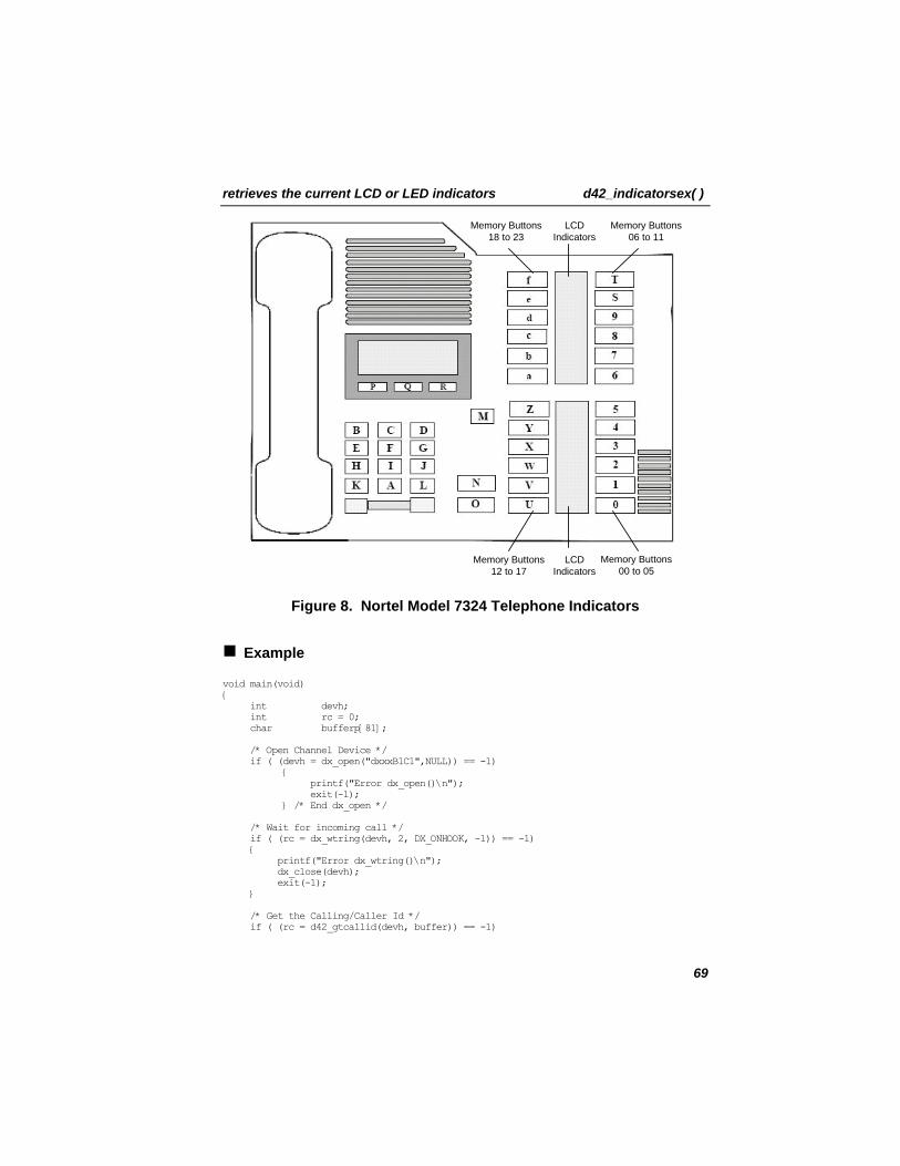
retrieves the current LCD or LED indicators d42_indicatorsex( )
Memory Buttons18 to 23
Memory Buttons06 to 11
Memory Buttons12 to 17
Memory Buttons00 to 05
LCDIndicators
LCDIndicators
Figure 8. Nortel Model 7324 Telephone Indicators
Example
void main(void) { int devh; int rc = 0; char bufferp[81]; /* Open Channel Device */ if ( (devh = dx_open("dxxxB1C1",NULL)) == -1) { printf("Error dx_open()\n"); exit(-1); } /* End dx_open */ /* Wait for incoming call */ if ( (rc = dx_wtring(devh, 2, DX_ONHOOK, -1)) == -1) { printf("Error dx_wtring()\n"); dx_close(devh); exit(-1); } /* Get the Calling/Caller Id */ if ( (rc = d42_gtcallid(devh, buffer)) == -1)
69

d42_indicatorsex( ) retrieves the current LCD or LED indicators
{ printf("Error d42_gtcallid()\n"); dx_close(devh); exit(-1); } /* End d42_gtcallid */ printf("Caller Id = %s\n",buffer); /* Get the Indicator Information */ if ( (rc = d42_indicatorsex(devh, buffer,80)) == -1) { printf("Error d42_indicatorsex(): Error Code: %hX\n",ATDV_LASTERR (devh)); dx_close(devh); exit(-1); } /* End d42_indicatorsex*/ for (count = 0; count < 80; count++) printf("Indicators = %X\n",buffer[count]); dx_close(devh); } /* End main */
Errors
If this function returns -1 to indicate a failure, one of the following (most common) codes will be contained in dx_errno. For a complete list of error codes and definitions, refer to Appendix C. ED42_BADDEVICE Invalid or wrong device handle ED42_UNSUPPORTED Function not supported on this board ED42_SYSTEM System level error ED42_INVALARG Invalid argument passed to function
70

sets a board or channel parameter d42_setparm( )
int d42_setparm(devh, parmnum, parmvalp) Name: Inputs: int devh • board or channel descriptor
int parmnum • parameter name void *parmvalp • pointer to an application buffer
containing the parameter value Returns: 0 • if success
-1 • if error; see Errors below D42LIB.H Includes: synchronous Mode:
Description
The d42_setparm( ) function sets a board or channel parameter. Depending on the parameter to be set, the value can be either a character string or an integer. The input board and channel parameter values for parmnum are listed in Table 3.
Parameter Description
devh specifies the valid board device or channel device descriptor obtained by a call to dx_open( )
parmnum contains the parameter name to update parmvalp application buffer containing the parameter value
NOTE: Setting board parameters affects all the channels on the board, but setting channel parameters affects only the specified channel.
To set board parameters, the following requirements must be met:
• the board must be open • all channels on the board must be closed
To set channel parameters, the following requirements must be met:
• the channel must be open • the channel must be idle
This function returns a failure if:
• the board or channel descriptor is invalid • any channels are open when setting board parameters
71

d42_setparm( ) sets a board or channel parameter
• when setting channel parameters, the channel is not open and idle • a read-only parm is specified • the value of parmnum is invalid • parmnum is not supported on the specified board • an MF parm is specified while MF detection is enabled
Cautions
When setting a parameter, the user passes a pointer to a variable containing the new parameter value. This variable should be treated as an unsigned integer for all parameters. The application should cast the parmvalp parameter to a (void *) to avoid compiler warnings.
Table 3. Board and Channel Parameters for d42_setparm( )
Board Parameters Description
D4BD_CALLID Enables caller ID. Values: 0 - disable (default) 1 - enable
D4BD_M1_DISPLAYWIDTH Sets the display width for Nortel M1 integration. Values: 0 - 2x24 size display (default) 1 - 2x33 size display
NOTE: When using 2x33 size displays, d42_display( ) will not return the entire display, d42_displayex( ) must be used.
D4CH_CHANNELSTATUS Receives asynchronous channel status messages. Values: 0 - disable (default) 1 - enable
Example
void main(void) { int devh; int rc = 0; unsigned int parmvalp = 1; /* Open Board Device */
72

sets a board or channel parameter d42_setparm( )
if ( (devh = dx_open("dxxxB1",NULL))==-1) { printf("Error dx_open()\n"); exit(-1); } /* End dx_open */ if ( (ATD4_BDTYPE ( devh )) == TYP_D82M1) { /* Set the Board Parameter To Enable Calling/Caller Id */ if ( (rc = d42_setparm(devh, D4BD_CALLID, (void *)&parmvalp)) == -1) { printf("Error d42_setparm(D4BD_CALLID)\n"); dx_close(devh); exit(-1); } /* End d42_setparm */ } /* end ATD4_BDTYPE */ dx_close(devh); } /* End main */
Errors
If this function returns -1 to indicate a failure, one of the following (most common) codes will be contained in dx_errno. For a complete list of error codes and definitions, refer to Appendix C. ED42_BADDEVICE Invalid or wrong device handle ED42_UNSUPPORTED Function not supported on this board ED42_SYSTEM System level error ED42_INVALARG Invalid argument passed to function
See Also
• d42_getparm( )
73


4. Programming Considerations
Specific information about using the Dialogic® D/42 runtime library to perform PBX functions is included in this chapter. A general description of the PBX functions and considerations unique to each supported PBX system are included for the following:
• Opening a channel on a Dialogic® PBX Integration Board • Accessing PBX features using dial strings
• Turn on/off message waiting indicators • Dial programmable keys • Call transfer
• Disconnect supervision • Converting existing D/4x applications into D/42 applications
4.1. Opening a Channel on the Dialogic® PBX Integration Board
Description
During initialization of the system, the Dialogic® R4 firmware file is downloaded to the board. Once firmware is downloaded, the appropriate PBX Signaling Link firmware load file is downloaded to a specified area in memory on the board. The PBXDRVR subsystem then downloads and starts this PBX Signaling Link firmware from its place in memory. The PBX Signaling Link firmware can then begin to synchronize with the PBX (assuming that the board is physically connected to the PBX). This process can take up to 60 seconds to complete. During this time period, the board should not receive any calls from the PBX. An application should check that the board is “alive” before any other functions are accessed.
NOTE: Failure to verify that the connection is established (synchronized) could cause unpredictable results.
After synchronization is complete, the dx_open( ) function is used to open the channel by using a valid device name to identify the channel to be opened. The
75

Dialogic® PBX Integration Software Reference
oflags parameter is used to set the attributes of the channel being opened. The attributes determine what types of I/O functions (recording and playback of voice data) can be performed on the open channel.
Example
int cd; /* channel descriptor */ int sysinit() {
/* open the channel VOXB0C0 */ if ((cd = dx_open("VOXB0C0",O_RDWR)) == -1) { /* process error */ exit(1); }
/* wait for 60 seconds for switch */ Sleep(60000L);
exit(0);
}
The dx_close( ) function is used to close a previously opened channel. Once the channel is closed, a process can no longer perform any action on that channel using that device handle. See the Dialogic Voice API Library Reference® for more information about the dx_open( ) and dx_close( ) functions.
4.2. Accessing PBX Features Using Dial Strings
You can choose to access PBX features such as turning on and off a message waiting indicator, dialing programmable keys, and transferring calls, using dial strings in the dx_dial( ) function. dx_dial( ) is a D/4x voice function. For detailed information on this function, see the Dialogic Voice API Library Reference® .
76

4. Programming Considerations
Input parameters for the dx_dial( ) function are defined as follows:
dx_dial( )Name: int dx_dial(cd, dialstrp, capp, mode) Inputs: int cd channel descriptor char *dialstrp pointer to ASCIIZ dial string DX_CAP *capp pointer to Call Progress Analysis Parameter
structure unsigned short mode asynchronous/synchronous setting and call
analysis flag
The dial string accepts escape sequences that are used to access PBX features. Acceptable ASCII characters for each dial string are the standard DTMF dialing and control characters described in the Dialogic Voice API Library Reference® , and the additional characters described in the following paragraphs.
The procedure for accessing a feature is as follows:
1. Set the hook state (on-hook or off-hook) required for dialing the feature dial string.
2. Use the appropriate dial string (e.g., <ESC>K).
NOTE: In some cases, a pause (“,”) may be needed after the entire dial string to give the switch enough time to respond to the command before issuing the next command.
4.2.1. On-Hook and Off-Hook Dialing Note
When using the Dialogic® PBX Integration Board with the supported MITEL and Siemens PBXs, it is possible to make a connection without explicitly going off-hook. With a channel in the on-hook state, if you dx_dial( ) a valid extension, you can make a connection. However, if you do a dx_sethook( ) to go back on-hook, you cannot go back to the on-hook state no matter how many on-hooks are performed. You must dx_sethook( ) off-hook, then on-hook (or dx_dial( ) the Release key, in the case of the Siemens).
77

Dialogic® PBX Integration Software Reference
4.2.2. Turn On the Message Waiting Indicator
Description
A dial string instructs the PBX to light the message waiting indicator on the specific extension. The dial string contains the following components:
<ESC> the ASCII escape character (0x1B)
command an ASCII character that identifies the “turn on message waiting indicator” feature
, pause (optional)
<extension> the number of the extension whose message waiting indicator is to be lit
The dial strings for supported PBXs are listed below.
NOTE: The pause in the dial string is sometimes needed to give the PBX time to activate the feature. The command character is case sensitive. Characters with the incorrect case are ignored.
NEC and Hicom 150 - Message Waiting Indicator (MWI) Requirement
The default access dial strings for the Dialogic® PBX Integration Board are set to **9 (on) and ##9 (off). If the PBX has not been set to use these dial strings, you must:
• Use the d42_setparm( ) function to change the following parameters to the dial string programmed on the PBX:
• D4BD_MSGACCESSON • D4BD_MSGACCESSOFF
OR
• Change the PBX access dial string to **9 (on) and ##9 (off).
78

4. Programming Considerations
Turn On the Message Waiting Indicator Dial String
<ESC>O,<extension>,<ESC>O
All PBXs - Except Nortel Meridian
For all supported PBXs except Nortel Meridian, use the following technique to turn on the MWI using dx_dial( ) and the dial string.
1. Go off-hook using dx_sethook( ).
2. Call the dx_dial( ) function. The dial string is <ESCO><extension><ESCO>.
3. Go on-hook using dx_sethook( ) again.
Use the optional pause character (comma) in the dial string when necessary.
Nortel Meridian - Exception
For the Nortel Meridian Switch only, skip items 1 and 3 above:
• The combined use of dx_sethook( ) and dx_dial( ) does not work for MWI.
• Use pause characters (comma) in the dial string to avoid problems.
Characters are case sensitive.
Example
unsigned int cd; /* channel descriptor */ char digstr[40]; int turn_on_mwl() { /* set up dial string */ switch (ATD4_CHTYPE(cd)) { case TYP_D82M1: case TYP_D82L4: case TYP_D82L2: sprintf(digstr,"%c0,555,%cO",ESC,ESC); break; } /* turn on message waiting indicator on ext. 555 */
79

Dialogic® PBX Integration Software Reference
if (dx_dial(cd,digstr,NULL,EV_SYNC) == -1) { printf("\nDial failed\n"); exit (1); } return (0); }
4.2.3. Turn Off the Message Waiting Indicator Dial String
Description
A dial string instructs the PBX to turn off the message waiting indicator on the specific extension. The dial string contains the following components:
<ESC> the ASCII escape character (1B hex)
command an ASCII character that identifies the “turn off message waiting indicator” feature
, pause (optional)
<extension> the number of the extension whose message waiting indicator is to be turned off
The dial strings for supported PBXs are listed below.
NOTE: The pause in the dial string is sometimes needed to give the PBX time to activate the feature. The command character is case sensitive. Characters with the incorrect case are ignored.
Turn Off the Message Waiting Indicator Dial String
<ESC>F,<extension>,<ESC>F
All PBXs - Except Nortel Meridian
For all supported PBXs except Nortel Meridian, use the following technique to turn off the MWI using dx_dial( ) and the dial string.
1. Go off-hook using dx_sethook( ).
80

4. Programming Considerations
2. Call the dx_dial( ) function. The dial string is <ESCF><extension><ESCF>.
3. Go on-hook using dx_sethook( ) again.
Use the optional pause character (comma) in the dial string when necessary.
Nortel Meridian - Exception
For the Nortel Meridian Switch only, skip items 1 and 3 above:
• The combined use of dx_sethook() and dx_dial() does not work for MWI.
• Use pause characters (comma) in the dial string to avoid problems.
Characters are case sensitive.
Example
unsigned int cd; /* channel descriptor */ char digstr[40]; int turn_off_mwl() { /* set up dial string */ switch (ATD4_CHTYPE(cd)) { case TYP_D82M1: case TYP_D82L4: case TYP_D82L2: sprintf(digstr,"%cF,555,%cF",ESC,ESC); break; } /* turn off message waiting indicator on ext. 555 */ if (dx_dial(cd,digstr,NULL,EV_SYNC) == -1) { printf("\nDial failed\n"); exit (1); } return (0); }
81

Dialogic® PBX Integration Software Reference
4.2.4. Dial Programmable Keys
Description
The dial string <ESC>K<key> enables the Dialogic® PBX Integration Board to access features programmed into the programmable keys available to extensions on the PBX. The dial string contains the following components:
<ESC> the ASCII escape character (1B hex)
K identifies the Dial Programmable Key feature
<key> indicates which programmable feature key to access
, pause (optional)
NOTE: The pause in the dial string may be needed to give the PBX time to activate the feature. The “K” and <key> characters are case sensitive. Dial strings using a lower case “k” are ignored. Use the correct case for the <key> characters to make sure the proper function is accessed.
Avaya Definity 7434 (4-Wire)
To access the dial string features on an Avaya 7434 4-wire telephone, refer to Figure 9 and use the direct key dialing sequences listed in Table 4. Also, refer to the Dialogic PBX Integration Board User’s Guide ® for more detailed information about programmable keys.
NOTE: When using the Dialogic® PBX Integration Board with an Avaya PBX, the inter-digit delay for dialing should be increased to equal or greater than 150 mS in the application. With the firmware default of 50 mS, the Avaya PBX’s DTMF detection sometimes fails to recognize back-to-back dialing of any digit.
82

4. Programming Considerations
gU
fT
eS
dR
cQ
bP
ZD N
YC M
G
I
XB L
F
H
WA K
J aE
ij
kl
O
hV
Message Select
on/off
Figure 9. Avaya 7434 (4-Wire) Telephone
83

Dialogic® PBX Integration Software Reference
Table 4. Avaya 7434 (4-Wire) Direct Key Dialing Sequences
Dial Code Key Description Feature Key 00 <ESC>KA Feature Key 01 <ESC>KB Feature Key 02 <ESC>KC Feature Key 03 <ESC>KD Feature Key 04 <ESC>KE Feature Key 05 <ESC>KF Feature Key 06 <ESC>KG Feature Key 07 <ESC>KH Feature Key 08 <ESC>KI Feature Key 09 <ESC>KJ Feature Key 10 <ESC>KK Feature Key 11 <ESC>KL Feature Key 12 <ESC>KM Feature Key 13 <ESC>KN Feature Key 14 <ESC>KO Feature Key 15 <ESC>KP Feature Key 16 <ESC>KQ Feature Key 17 <ESC>KR Feature Key 18 <ESC>KS Feature Key 19 <ESC>KT Feature Key 20 <ESC>KU Feature Key 21 <ESC>KV Feature Key 22 <ESC>KW Feature Key 23 <ESC>KX Feature Key 24 <ESC>KY
<ESC>KZ Feature Key 25
84

4. Programming Considerations
Dial Code Key Description Feature Key 26 <ESC>Ka Feature Key 27 <ESC>Kb Feature Key 28 <ESC>Kc Feature Key 29 <ESC>Kd Feature Key 30 <ESC>Ke Feature Key 31 <ESC>Kf Feature Key 32 <ESC>Kg Feature Key 33 <ESC>Kh Hold <ESC>Ki Drop <ESC>Kj Transfer <ESC>Kk Conference <ESC>Kl
<ESC>DI Enable in-band signaling <ESC>DO Enable out-of-band signaling
85

Dialogic® PBX Integration Software Reference
Avaya Definity 8434 (2-Wire)
To access the dial string features on a 2-wire Avaya 8434 telephone, refer to Figure 10 and use the direct key dialing sequences listed in Table 5. Also, refer to the Dialogic PBX Integration Board User’s Guide ® for more detailed information about programmable keys.
NOTE: When using the Dialogic® PBX Integration Board with an Avaya PBX, the inter-digit delay for dialing should be increased to equal or greater than 150 mS in the application. With the firmware default of 50 mS, the Avaya PBX’s DTMF detection sometimes fails to recognize back-to-back dialing of any digit.
U
V
S
R
Q
P
M
L
T
a
Z
Y
W
b
g
h
d
D
E
B
A
C
G
H
I
J
F
m n
r
po
s
q
O
N
K
X
c
e
f
Figure 10. Avaya 8434 (2-Wire) Telephone
86

4. Programming Considerations
Table 5. Avaya 8434DX (2-Wire) Direct Key Dialing Sequences
Dial Code Key Description Feature Key 00 <ESC>KA Feature Key 01 <ESC>KB Feature Key 02 <ESC>KC Feature Key 03 <ESC>KD Feature Key 04 <ESC>KE Feature Key 05 <ESC>KF Feature Key 06 <ESC>KG Feature Key 07 <ESC>KH Feature Key 08 <ESC>KI Feature Key 09 <ESC>KJ Feature Key 10 <ESC>KK Feature Key 11 <ESC>KL Feature Key 12 <ESC>KM Feature Key 13 <ESC>KN Feature Key 14 <ESC>KO Feature Key 15 <ESC>KP Feature Key 16 <ESC>KQ Feature Key 17 <ESC>KR Feature Key 18 <ESC>KS Feature Key 19 <ESC>KT Feature Key 20 <ESC>KU Feature Key 21 <ESC>KV Feature Key 22 <ESC>KW Feature Key 23 <ESC>KX Feature Key 24 <ESC>KY
<ESC>KZ Feature Key 25
87

Dialogic® PBX Integration Software Reference
Dial Code Key Description Feature Key 26 <ESC>Ka Feature Key 27 <ESC>Kb Feature Key 28 <ESC>Kc Feature Key 29 <ESC>Kd Feature Key 30 <ESC>Ke Feature Key 31 <ESC>Kf Feature Key 32 <ESC>Kg Feature Key 33 <ESC>Kh Hold <ESC>Ki Drop <ESC>Kj Transfer <ESC>Kk Conference <ESC>Kl Display Key 0 <ESC>Km Display Key 1 <ESC>Kn Display Key 2 <ESC>Ko Display Key 3 <ESC>Kp Display Key 4 <ESC>Kq Display Key 5 - Menu <ESC>Kr Display Key 6- Exit <ESC>Ks
<ESC>DI Enable in-band signaling <ESC>DO Enable out-of-band signaling
NOTE: The Dialogic® PBX Integration Board does not currently support the Shift, Test, Mute, and Speaker feature buttons, nor does it support the Prev and Next display keys. In Figure 10 above, these keys are shown without an assigned dialing sequence.
88

4. Programming Considerations
Siemens ROLM
To access the dial string features on a Siemens ROLMphone 400, refer to Figure 11 and use the direct key dialing sequences listed in Table 6. Also, refer to the Dialogic PBX Integration Board User’s Guide ® for more detailed information about programmable keys.
i
ZUPKF
B e
j
aVQLG
C f
k
bWRMH
D
cXSNI
g
h
YTOJE
A d
CALL WAITING
Figure 11. ROLMphone 400 Telephone
89

Dialogic® PBX Integration Software Reference
Table 6. Siemens ROLMphone 400 Direct Key Dialing Sequences
Dial Code Key Description
<ESC>K0 Dialpad 0 <ESC>K1 Dialpad 1 <ESC>K2 Dialpad 2 <ESC>K3 Dialpad 3 <ESC>K4 Dialpad 4 <ESC>K5 Dialpad 5 <ESC>K6 Dialpad 6 <ESC>K7 Dialpad 7 <ESC>K8 Dialpad 8 <ESC>K9 Dialpad 9 <ESC>K* Dialpad * <ESC>K# Dialpad # <ESC>KA Feature Key 09 - LINE <ESC>KB Feature Key 08 <ESC>KC Feature Key 07 <ESC>KD Feature Key 06 - CLEAR <ESC>KE Feature Key 05 <ESC>KF Feature Key 04 - DDS (for Message Waiting Light OFF) <ESC>KG Feature Key 03 - DDS (for Message Waiting Light ON) <ESC>KH Feature Key 02 <ESC>KI Feature Key 01 - MAILBOX (MWL) <ESC>KJ Feature Key 15 <ESC>KK Feature Key 14 <ESC>KL Feature Key 13 <ESC>KM Feature Key 12 <ESC>KN Feature Key 11
90

4. Programming Considerations
Dial Code Key Description
<ESC>KO Feature Key 20 - PROG <ESC>KP Feature Key 19 <ESC>KQ Feature Key 18 <ESC>KR Feature Key 17 <ESC>KS Feature Key 16 <ESC>KT Feature Key 25 <ESC>KU Feature Key 24 <ESC>KV Feature Key 23 <ESC>KW Feature Key 22 <ESC>KX Feature Key 21 <ESC>KY Feature Key 35 <ESC>KZ Feature Key 34 <ESC>Ka Feature Key 33 <ESC>Kb Feature Key 32 <ESC>Kc Feature Key 31 <ESC>Kd Feature Key 29 <ESC>Ke Feature Key 28 <ESC>Kf Feature Key 27 <ESC>Kg Feature Key 26 <ESC>Kh Feature Key 37 - MWCTR <ESC>Ki Feature Key 36 - SPEAKER <ESC>Kj Feature Key 40 - Volume Down <ESC>Kk Feature Key 39 - Volume Up <ESC>Kl Feature Key 10 <ESC>Km Feature Key 30 <ESC>Kn Feature Key 38 - XFER <ESC>DI Enable in-band signaling <ESC>DO Enable out-of-band signaling
91

Dialogic® PBX Integration Software Reference
Siemens Hicom
To access the dial string features on a Siemens Hicom Optiset E telephone, depending on which PBX is being used, refer to Figure 12 and Figure 13, along with the direct key dialing sequences listed in Table 7 and Table 8. Also, refer to the Dialogic PBX Integration Board User’s Guide ® for more detailed information about programmable keys.
�
� � �
�
�
�
�
�
�
�
�
�
�
�
�
� �
�
�
�
�
��
�
���� ! !!
#�$%!& &'#�
��#(� )) *!�
�'��
�'��
�'��
��#(� )) *!�
� '!*#+
!!* ,- ��#(� )) *!�
��#(� )) *!�
��#(� )) *!�
Figure 12. Siemens Optiset E Telephone with a Hicom 150
92

4. Programming Considerations
Table 7. Siemens Hicom Optiset E Direct Key Dialing Sequences with Hicom 150
Dial Code Key Description
<ESC>K0 Dialpad 0 <ESC>K1 Dialpad 1 <ESC>K2 Dialpad 2 <ESC>K3 Dialpad 3 <ESC>K4 Dialpad 4 <ESC>K5 Dialpad 5 <ESC>K6 Dialpad 6 <ESC>K7 Dialpad 7 <ESC>K8 Dialpad 8 <ESC>K9 Dialpad 9 <ESC>K* Dialpad * <ESC>K# Dialpad # <ESC>KA Feature Key 00 - Programmable <ESC>KB Feature Key 01 - Programmable <ESC>KC Feature Key 02 - Programmable <ESC>KD Feature Key 03 - Programmable <ESC>KE Feature Key 04 - Programmable <ESC>KF Feature Key 05 - Programmable <ESC>KG Feature Key 06 - Consultation <ESC>KH Feature Key 07 - Programmable <ESC>KI Feature Key 08 - Programmable <ESC>KJ Feature Key 09 - Programmable <ESC>KK Feature Key 10 - Programmable <ESC>KL Feature Key 11 - General Call <ESC>KM Select OptiGuide key (for selecting display options)
93

Dialogic® PBX Integration Software Reference
Dial Code Key Description
<ESC>KN Scroll Back OptiGuide key (for scrolling display options) <ESC>KO Scroll Forward OptiGuide key (for scrolling display options) <ESC>KP Plus (+) key <ESC>KQ Minus (-) key <ESC>DI Enable in-band signaling <ESC>DO Enable out-of-band signaling
94

4. Programming Considerations
L
M N O
K
J
I
HD
C
B
A
G
E
F
1
P
Q
8
2 3
4
7
5
9
0*
6
General Call
Consultation
Programmable
Line
Line
Line
MWL_OFF
Mailbox
Callback Programmable
Programmable
MWL_ON
Figure 13. Siemens Optiset E Telephone with a Hicom 300
95

Dialogic® PBX Integration Software Reference
Table 8. Siemens Hicom Optiset E Direct Key Dialing Sequences with Hicom 300
Dial Code Key Description
<ESC>K0 Dialpad 0 <ESC>K1 Dialpad 1 <ESC>K2 Dialpad 2 <ESC>K3 Dialpad 3 <ESC>K4 Dialpad 4 <ESC>K5 Dialpad 5 <ESC>K6 Dialpad 6 <ESC>K7 Dialpad 7 <ESC>K8 Dialpad 8 <ESC>K9 Dialpad 9 <ESC>K* Dialpad * <ESC>K# Dialpad # <ESC>KA Feature Key 00 - Mailbox <ESC>KB Feature Key 01 - Callback <ESC>KC Feature Key 02 - (Configure to dial MWL_ON) <ESC>KD Feature Key 03 - (Configure to dial MWL_OFF) <ESC>KE Feature Key 04 - Programmable <ESC>KF Feature Key 05 - Programmable <ESC>KG Feature Key 06 - Consultation <ESC>KH Feature Key 07- Line <ESC>KI Feature Key 08 - Line <ESC>KJ Feature Key 09 - Line <ESC>KK Feature Key 10 - Line <ESC>KL Feature Key 11 - General Call <ESC>KM Select OptiGuide key (for selecting display options)
96

4. Programming Considerations
Dial Code Key Description
<ESC>KN Scroll Back OptiGuide key (for scrolling display options) <ESC>KO Scroll Forward OptiGuide key (for scrolling display options) <ESC>KP Plus (+) key <ESC>KQ Minus (-) key <ESC>DI Enable in-band signaling <ESC>DO Enable out-of-band signaling
97

Dialogic® PBX Integration Software Reference
MITEL SX Series PBXs
To access the dial string features on MITEL SUPERSET 420 and 430 telephones, refer to Figure 14 and Figure 15, along with the direct key dialing sequences listed in Table 9 and Table 10. Also, refer to the Dialogic PBX Integration Board User’s Guide
®
for more detailed information about programmable keys.
*
7
41
0
8
52
#
9
63
M
b ca
Q
N T
P
U
VO
S
R
Figure 14. MITEL SUPERSET 420 Telephone
98

4. Programming Considerations
Table 9. MITEL SX SUPERSET 420 Direct Key Dialing Sequences
Dial Code Key Description <ESC>K0 Dialpad 0 <ESC>K1 Dialpad 1 <ESC>K2 Dialpad 2 <ESC>K3 Dialpad 3 <ESC>K4 Dialpad 4 <ESC>K5 Dialpad 5 <ESC>K6 Dialpad 6 <ESC>K7 Dialpad 7 <ESC>K8 Dialpad 8 <ESC>K9 Dialpad 9 <ESC>K* Dialpad * <ESC>K# Dialpad #
Personal Key 00 <ESC>KA Personal Key 06 <ESC>KB Personal Key 01 <ESC>KC Personal Key 07 <ESC>KD Personal Key 02 <ESC>KE Personal Key 08 <ESC>KF Personal Key 03 <ESC>KG Personal Key 09 <ESC>KH Personal Key 04 <ESC>KI Personal Key 10 <ESC>KJ Personal Key 05 <ESC>KK Personal Key 11 <ESC>KL Message Key <ESC>KM
<ESC>KN SuperKey
99

Dialogic® PBX Integration Software Reference
Dial Code Key Description Cancel <ESC>KO Microphone <ESC>KP Hold <ESC>KQ Redial <ESC>KR Speaker <ESC>KS Trans/Conf <ESC>KT V/T/C up <ESC>KU V/T/C down <ESC>KV Left Softkey <ESC>Ka Middle Softkey <ESC>Kb Right Softkey <ESC>Kc
<ESC>DI Enable in-band signaling <ESC>DO Enable out-of-band signaling
100
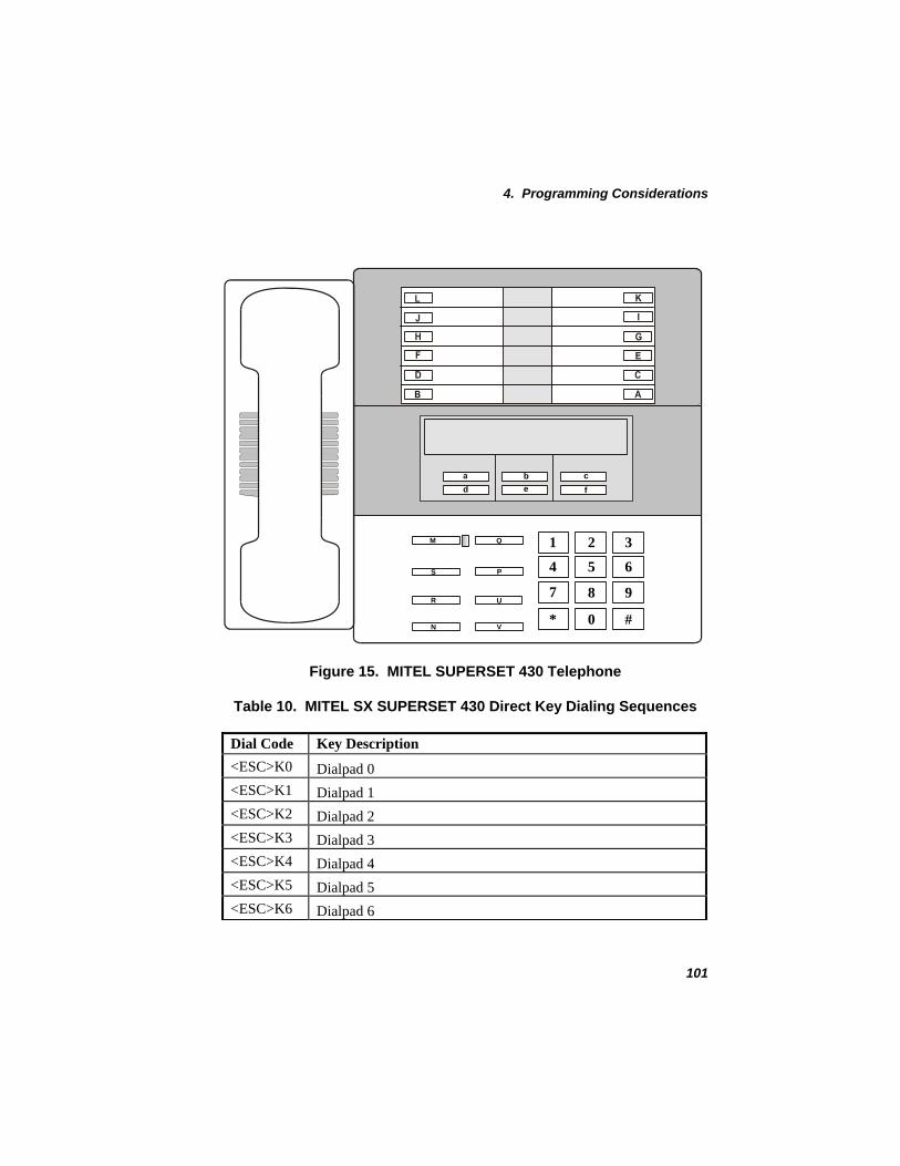
4. Programming Considerations
bfc
e
*
7
4
1
0
8
5
2
#
9
6
3M Q
U
VN
R
S P
d
Figure 15. MITEL SUPERSET 430 Telephone
Table 10. MITEL SX SUPERSET 430 Direct Key Dialing Sequences
Dial Code Key Description <ESC>K0 Dialpad 0 <ESC>K1 Dialpad 1 <ESC>K2 Dialpad 2 <ESC>K3 Dialpad 3 <ESC>K4 Dialpad 4 <ESC>K5 Dialpad 5 <ESC>K6 Dialpad 6
101

Dialogic® PBX Integration Software Reference
Dial Code Key Description <ESC>K7 Dialpad 7 <ESC>K8 Dialpad 8 <ESC>K9 Dialpad 9 <ESC>K* Dialpad * <ESC>K# Dialpad #
Personal Key 00 <ESC>KA Personal Key 06 <ESC>KB Personal Key 01 <ESC>KC Personal Key 07 <ESC>KD Personal Key 02 <ESC>KE Personal Key 08 <ESC>KF Personal Key 03 <ESC>KG Personal Key 09 <ESC>KH Personal Key 04 <ESC>KI Personal Key 10 <ESC>KJ Personal Key 05 <ESC>KK Personal Key 11 <ESC>KL Message Key <ESC>KM SuperKey <ESC>KN Not used<ESC>KO Microphone <ESC>KP Hold <ESC>KQ Applications <ESC>KR Speaker <ESC>KS Not used<ESC>KT V/T/C up <ESC>KU V/T/C down <ESC>KV
<ESC>Ka Top Left Softkey
102

4. Programming Considerations
Dial Code Key Description Top Middle Softkey <ESC>Kb Top Right Softkey <ESC>Kc Bottom Left Softkey <ESC>Kd Bottom Middle Softkey <ESC>Ke Bottom Right Softkey <ESC>Kf Enable in-band signaling <ESC>DI
<ESC>DO Enable out-of-band signaling
103

Dialogic® PBX Integration Software Reference
Nortel Norstar and BCM
To access the dial string features on a Nortel Model 7324 telephone, refer to Figure 16 while using the direct key dialing sequences listed in Table 11. Also, refer to the Dialogic PBX Integration Board User’s Guide ® for more detailed information about programmable keys.
NOTE: For in-band and out-of-band signaling, the default is set to out-of-band. To invoke in-band signaling, use the <ESC>DI dial string. The signaling will remain in-band until either the dx_sethook( ) function is used to go on-hook, or the <ESC>DO dial string is used.
9
8
K
H
E
B
A
I
F
C
L
J
G
D
O
N
M
7
6
5
3
2
1
0
4
P Q R
V
Ua
W
X
Y
Z
b
c
d
e
f
T
S
Figure 16. Nortel M7324 Telephone
104

4. Programming Considerations
Table 11. Nortel Norstar and BCM M7324 Direct Key Dialing Sequences
Dial Code Key Description
<ESC>K0 Memory Button 00 <ESC>K1 Memory Button 01 <ESC>K2 Memory Button 02 <ESC>K3 Memory Button 03 <ESC>K4 Memory Button 04 <ESC>K5 Memory Button 05 <ESC>K6 Memory Button 06 <ESC>K7 Memory Button 07 <ESC>K8 Memory Button 08 <ESC>K9 Memory Button 09 <ESC>KA Dialpad 0 <ESC>KB Dialpad 1 <ESC>KC Dialpad 2 <ESC>KD Dialpad 3 <ESC>KE Dialpad 4 <ESC>KF Dialpad 5 <ESC>KG Dialpad 6 <ESC>KH Dialpad 7 <ESC>KI Dialpad 8 <ESC>KJ Dialpad 9 <ESC>KK Dialpad * <ESC>KL Dialpad # <ESC>KM Release <ESC>KN Feature <ESC>KO Hold
105

Dialogic® PBX Integration Software Reference
Dial Code Key Description
<ESC>KP Display button 00 <ESC>KQ Display button 01 <ESC>KR Display button 02 <ESC>KS Memory Button 10 <ESC>KT Memory Button 11 <ESC>KU Memory Button 12 <ESC>KV Memory Button 13 <ESC>KW Memory Button 14 <ESC>KX Memory Button 15 <ESC>KY Memory Button 16 <ESC>KZ Memory Button 17 <ESC>Ka Memory Button 18 <ESC>Kb Memory Button 19 <ESC>Kc Memory Button 20 <ESC>Kd Memory Button 21 <ESC>Ke Memory Button 22 <ESC>Kf Memory Button 23 <ESC>DI Enable in-band signaling <ESC>DO Enable out-of-band signaling
106

4. Programming Considerations
Nortel Meridian 1 M2616
To access the dial string features on a Nortel Model 2616 telephone, refer to Figure 17 and use the direct key dialing sequences listed in Table 12. Also, refer to the Dialogic PBX Integration Board User’s Guide ® for more detailed information about programmable keys.
J
K
L
M
N
O
P
I
*
7
4
1
0
8
5
2
#
9
6
3
H
G
F
D
C
B
A
E
Q
R
Figure 17. Nortel Meridian 1 M2616 Telephone
107

Dialogic® PBX Integration Software Reference
Table 12. Nortel Meridian 1 M2616 Direct Key Dialing Sequences
Dial Code Key Description
<ESC>K0 Dialpad 0 <ESC>K1 Dialpad 1 <ESC>K2 Dialpad 2 <ESC>K3 Dialpad 3 <ESC>K4 Dialpad 4 <ESC>K5 Dialpad 5 <ESC>K6 Dialpad 6 <ESC>K7 Dialpad 7 <ESC>K8 Dialpad 8 <ESC>K9 Dialpad 9 <ESC>K* Dialpad * <ESC>K# Dialpad #
Feature Key 00 - Primary Call <ESC>KA Feature Key 01 <ESC>KB Feature Key 02 <ESC>KC Feature Key 03 - Transfer <ESC>KD Feature Key 04 <ESC>KE Feature Key 05 <ESC>KF Feature Key 06 <ESC>KG Feature Key 07 - Program <ESC>KH Feature Key 08 <ESC>KI Feature Key 09 <ESC>KJ Feature Key 10 <ESC>KK Feature Key 11 <ESC>KL Feature Key 12 <ESC>KM
<ESC>KN Feature Key 13
108

4. Programming Considerations
Dial Code Key Description Feature Key 14 <ESC>KO Feature Key 15 <ESC>KP
<ESC>KQ Hold <ESC>KR Release <ESC>DI Enable in-band signaling <ESC>DO Enable out-of-band signaling
109

Dialogic® PBX Integration Software Reference
NEC KTS/PBX
To access the dial string features on a DTerm Series III telephone, refer to Figure 18 and use the direct key dialing sequences listed in Table 13. Also, refer to the Dialogic PBX Integration Board User’s Guide® for more detailed information about programmable keys.
NOTE: For in-band and out-of-band signaling, the default is set to out-of-band. To invoke in-band signaling, use the <ESC>DI dial string. The signaling will remain in-band until either the dx_sethook( ) function is used to go on-hook, or the <ESC>DO dial string is used.
W X Y Z
a b c d
e f g h
i j k l
1 2 3
4 5 6
7 8 9
K
L
I
H
NMGJ
CBA
U V
m n
o p
q r
s t
u v
w x
y z
( )
+ /
< >
Figure 18. NEC DTerm III Telephone
110

4. Programming Considerations
Table 13. NEC KTS/PBX Direct Key Dialing Sequences
Dial Code Key Description
<ESC>K1 Dialpad 1 <ESC>K2 Dialpad 2 <ESC>K3 Dialpad 3 <ESC>K4 Dialpad 4 <ESC>K5 Dialpad 5 <ESC>K6 Dialpad 6 <ESC>K7 Dialpad 7 <ESC>K8 Dialpad 8 <ESC>K9 Dialpad 9 <ESC>KA Dialpad 0 <ESC>KB Dialpad * <ESC>KC Dialpad # <ESC>KG Function key 0 - TRF <ESC>KH Function key 1 - LNR <ESC>KI Function key 2 - CNF <ESC>KJ Function key 3 - HOLD <ESC>KK Function key 4 - RECALL <ESC>KL Function key 5 - FNC <ESC>KM Function key 6 - ANS <ESC>KN Function key 7 - SPKR <ESC>KU Volume up <ESC>KV Volume down <ESC>KW Line key 1 <ESC>KX Line key 2 <ESC>KY Line key 3 <ESC>KZ Line key 4
111

Dialogic® PBX Integration Software Reference
Dial Code Key Description
<ESC>Ka Line key 5 <ESC>Kb Line key 6 <ESC>Kc Line key 7 <ESC>Kd Line key 8 <ESC>Ke Line key 9 <ESC>Kf Line key 10 <ESC>Kg Line key 11 <ESC>Kh Line key 12 <ESC>Ki Line key 13 <ESC>Kj Line key 14 <ESC>Kk Line key 15 <ESC>Kl Line key 16 <ESC>Km Direct Station Select (DDS) key 1 <ESC>Kn Direct Station Select (DDS) key 2 <ESC>Ko Direct Station Select (DDS) key 3 <ESC>Kp Direct Station Select (DDS) key 4 <ESC>Kq Direct Station Select (DDS) key 5 <ESC>Kr Direct Station Select (DDS) key 6 <ESC>Ks Direct Station Select (DDS) key 7 <ESC>Kt Direct Station Select (DDS) key 8 <ESC>Ku Direct Station Select (DDS) key 9 <ESC>Kv Direct Station Select (DDS) key 10 <ESC>Kw Direct Station Select (DDS) key 11 <ESC>Kx Direct Station Select (DDS) key 12 <ESC>Ky Direct Station Select (DDS) key 13 <ESC>Kz Direct Station Select (DDS) key 14 <ESC>K( Direct Station Select (DDS) key 15 <ESC>K) Direct Station Select (DDS) key 16
112

4. Programming Considerations
Dial Code Key Description
<ESC>K+ Direct Station Select (DDS) key 17 <ESC>K/ Direct Station Select (DDS) key 18 <ESC>K< Direct Station Select (DDS) key 19 <ESC>K> Direct Station Select (DDS) key 20 <ESC>DI Enable in-band DTMF signaling <ESC>DO Enable out-of-band DTMF signaling
Example
int cd; /* channel descriptor */ char digstr[40]; int set_dpk() {
/* set up dial string to press Speaker key */ switch (ATD4_CHTYPE(cd)) { case TYP_D82M1: sprintf(digstr,"%cKD",ESC); break; case TYP_D82L4: case TYP_D82L2: sprintf(digstr,"%cKl",ESC); break;
} /* Program dial programmable key */ if (dx_dial(cd,digstr,NULL, EV_SYNC)) { printf("\nDial failed\n"); exit(1); }
exit(0); }
113
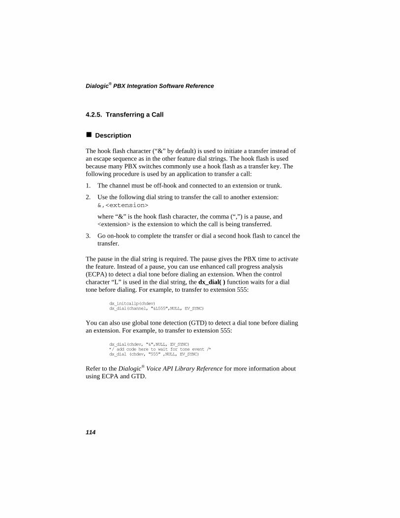
Dialogic® PBX Integration Software Reference
4.2.5. Transferring a Call
Description
The hook flash character (“&” by default) is used to initiate a transfer instead of an escape sequence as in the other feature dial strings. The hook flash is used because many PBX switches commonly use a hook flash as a transfer key. The following procedure is used by an application to transfer a call:
1. The channel must be off-hook and connected to an extension or trunk.
2. Use the following dial string to transfer the call to another extension: &,<extension>
where “&” is the hook flash character, the comma (“,”) is a pause, and <extension> is the extension to which the call is being transferred.
3. Go on-hook to complete the transfer or dial a second hook flash to cancel the transfer.
The pause in the dial string is required. The pause gives the PBX time to activate the feature. Instead of a pause, you can use enhanced call progress analysis (ECPA) to detect a dial tone before dialing an extension. When the control character “L” is used in the dial string, the dx_dial( ) function waits for a dial tone before dialing. For example, to transfer to extension 555:
dx_initcallp(chdev) dx_dial(channel, "&L555",NULL, EV_SYNC)
You can also use global tone detection (GTD) to detect a dial tone before dialing an extension. For example, to transfer to extension 555:
dx_dial(chdev, "&",NULL, EV_SYNC) */ add code here to wait for tone event /* dx_dial (chdev, "555" ,NULL, EV_SYNC)
Refer to the Dialogic Voice API Library Reference ® for more information about using ECPA and GTD.
114

4. Programming Considerations
Example
int cd; /* channel descriptor */ char digstr[40]; int transfer_call() { /* transfer the call */ if (dx_dial(cd,"&,555",NULL,EV_SYNC) == -1) { printf("\nDial failed\n"); exit (1); } /* set the channel onhook after the transfer */ if (dx_sethook(cd, DX_ONHOOK, EV_SYNC) == -1) { /* process error */ exit(1); } exit (0); }
4.2.6. In-Band/Out-of-Band Signaling
In-band signaling is a method used by analog (2500) telephones to communicate with PBXs (e.g., calling into a PBX and using DTMF to respond to voice prompts). In-band signals use the same band of frequencies as the voice signal. The in-band signaling method provides limited integration because there are no standards and different PBXs provide varying levels of control.
Out-of-band signaling is used by PBXs to communicate with their station sets or a CT computer. Out-of-band signals do not use the band of frequencies used by the voice signals. The PBX transmits data that can include information such as called/calling number ID. Because of its versatility, out-of-band signaling is a comparatively preferred method.
In-band signaling must be used when DTMF tones are required to communicate (e.g., connecting two voice mail systems through a CO using AMIS--Automated Messaging Interchange Specification). If out-of-band signaling is used, timing problems may occur because digit data (dial pad) sent from the station set (or from the Dialogic® PBX Integration Board) to the PBX are converted to DTMF and then sent to the CO.
115

Dialogic® PBX Integration Software Reference
Dialogic® PBX Integration Boards can be set to communicate using either in-band or out-of-band signaling (see Table 14). Characters are not case sensitive for this dial string.
Table 14. Setting In-Band and Out-of-Band Signaling
DTMF Signaling PBX In-Band Out-of-Band Default Signaling
Avaya 4-wire <ESC>DI <ESC>DO In-band Avaya 2-wire <ESC>DI <ESC>DO In-band Siemens ROLM CBX 9005, 9006, and 9715
<ESC>DI <ESC>DO Out-of-band
Siemens Hicom 150 and 300
<ESC>DI <ESC>DO Out-of-band
MITEL SX Series <ESC>DI <ESC>DO Out-of-band NEC Electra Elite (KTS) NEC Electra Professional 120 (KTS)
<ESC>DI <ESC>DO Out-of-band
NEC NEAX 2400 IMS (PBX) NEC NEAX 2000 IVS, IVS2, IPS (PBX)
<ESC>DI <ESC>DO Out-of-band
Nortel Meridian 1 <ESC>DI <ESC>DO Out-of-band Nortel Norstar DR5, CICS, and MICS
<ESC>DI <ESC>DO Out-of-band
NOTE: When using <ESC>DI and <ESC>DO to set the DTMF signaling method, the PBX Integration Board channel returns to its default state (out-of-band signaling) after a dx_sethook( ) function is called.
Example
unsigned int cd; /* channel descriptor */ char digstr[40]; int set_dtmf_signaling()
116

4. Programming Considerations
{ /* set up dial string */ switch (ATD4_CHTYPE(cd)) { case TYP_D82M1: case TYP_D82L4: case TYP_D82L2: sprintf(digstr,"%cDI",ESC); break; } /* set DTMF signaling to in-band */ if (dx_dial(cd,digstr,NULL,EV_SYNC) == -1) { printf("\nDial failed\n"); exit (1); } return (0); }
4.2.7. Disconnect Supervision
Description
Disconnect supervision for Dialogic® PBX Integration Boards functions the same as other Dialogic® D/4x Boards. Refer to the Dialogic Voice API Library Reference
®
for a description of using I/O terminations to perform disconnect supervision in an application.
As part of disconnect supervision, the PBX Integration Boards monitor communications with the PBX. If communication is lost with the PBX for 60 seconds, the firmware forces a loop current drop condition until communication is re-established.
NOTE: Disconnect supervision is always available for internal calls; however, for external or trunk calls, it is available only if the trunk module handles disconnect supervision.
4.2.8. Converting Existing D/4x Applications
Description
The Dialogic® PBX Integration Boards and the Dialogic® D/42-xx and D/41 Voice Boards use the same Dialogic® D/4x Voice library and supporting library.
117

Dialogic® PBX Integration Software Reference
However, some modifications are required to convert an existing D/4x application into a PBX integration application. This conversion only includes new functions provided by the D/42 runtime library. Use the following guidelines to convert an existing D/4x application to an application that uses the D/42 runtime library:
NOTE: Like D/42-xx applications, all PBX Integration Board applications must take into account the delay waiting for loop current to be detected that exists when opening the board with the dx_open( ) library function.
• To convert an existing application without using the Dialogic® Unified API or called/calling number ID, use the dx_cdbuf( ) function immediately after the application receives a rings-received event to clear the called/calling number ID digits from the digit buffer. This prevents the called/calling number ID from interfering with what the application expects to find in the digit buffer. Alternately, use the dx_gtdigbuf( ) function to retrieve the called/calling number ID and then discard the retrieved string. To access the other PBX features, the application must use the dial strings in the dx_dial( ) function, using the format described in Section 4.2. Accessing PBX Features Using Dial Strings.
• To convert an existing application without using the Unified API but using called/calling number ID, use the dx_gtdigbuf( ) function to retrieve the called/calling number ID digits and place them in the digit buffer. To access the other PBX features, the application must use the dial strings in the dx_dial( ) function, using the format described in Section 4.2. Accessing PBX Features Using Dial Strings.
• To convert an existing application using the Unified API to retrieve the called/calling number ID, use the dx_gtcallid( ) function to retrieve the called/calling number ID digits and place them in the application buffer. Refer to Section 3. Unified API Function Reference. To access the other PBX features, the application must use the dial strings in the dx_dial( ) function, and the dial string format must be as described in Section 4.2. Accessing PBX Features Using Dial Strings.
118

Appendix A Unified API Quick Reference
ATD4_BDTYPE( ) retrieves the PBX integration board type
int ATD4_BDTYPE(devh) Name: Inputs: int devh • board descriptor
Returns: board type • returns board type information 0 • if success -1 • if error; see Appendix C.
D42LIB.H Includes: synchronous Mode:
ATD4_CHTYPE( ) retrieves the PBX integration channel type
int ATD4_CHTYPE(devh) Name: Inputs: int devh • channel descriptor
Returns: channel type • returned channel type information 0 • if success -1 • if error; see Appendix C
D42LIB.H Includes: synchronous Mode:
d42_brdstatus( ) retrieves the current PBX integration board status
int d42_brdstatus(devh, buffstatus, bufferp) Name: Inputs: int devh • board descriptor
char *buffstatus • pointer to buffer containing board status information
char *bufferp • reserved for future use Returns: 0 • if success
-1 • if error; see Appendix C D42LIB.H Includes: synchronous Mode:
119

Dialogic® PBX Integration Software Reference
d42_chnstatus( ) retrieves the current channel status
int d42_chnstatus(devh, statusp, bufferp) Name: Inputs: int devh • channel descriptor
char *statusp • pointer to buffer containing channel status information
char *bufferp • reserved for future use Returns: 0 • if success
-1 • if error; see Appendix C D42LIB.H Includes: synchronous Mode:
d42_dial( ) dials an ASCIIZ string
int d42_dial(devh, bufferp) Name: Inputs: int devh • board descriptor
char *bufferp • pointer to an application buffer containing the dial string
Returns: 0 • if success -1 • if error; see Appendix C
D42LIB.H Includes: synchronous Mode:
d42_display( ) retrieves the current LCD display
int d42_display(devh, bufferp) Name: Inputs: int devh • channel descriptor
char *bufferp • pointer to an application buffer. The buffer will contain display data for the selected channel.
Returns: 0 • if success -1 • if error; see Appendix C
D42LIB.H Includes: synchronous Mode:
120

Appendix A
d42_displayex( ) retrieves the current extended LCD display
int d42_displayex(devh, bufferp, buflen) Name: Inputs: int devh • channel descriptor
char *bufferp • pointer to an application buffer. The buffer will contain display data for the selected channel.
buflen • length of buffer on entry Returns: 0 • if success
-1 • if error; see Appendix C D42LIB.H Includes: synchronous Mode:
d42_getparm( ) gets a PBX integration board or channel parameter
int d42_getparm(devh, parmnum, parmvalp) Name: Inputs: int devh • board or channel descriptor
unsigned short parmnum • parameter name void *parmvalp • pointer to parameter value
Returns: 0 • if success -1 • if error; see Appendix C
D42LIB.H Includes: synchronous Mode:
d42_getver( ) retrieves the firmware or library version
int d42_getver(devh, bufferp, flag) Name: Inputs: int devh • board descriptor
char *bufferp • pointer to an application buffer containing version information
int flag • determines if firmware or library version is retrieved
Returns: 0 • if success -1 • if error; see Appendix C
D42LIB.H Includes: synchronous Mode:
121

Dialogic® PBX Integration Software Reference
d42_gtcallid( ) retrieves the called/calling number ID
int d42_gtcallid(devh, bufferp) Name: Inputs: int devh • channel descriptor
char *bufferp • pointer to an application buffer containing called/calling number ID data
Returns: 0 • if success -1 • if error; see Appendix C
D42LIB.H Includes: synchronous Mode:
d42_gtcallidex( ) retrieves call information
int d42_gtcallid(devh, *pcallidex) Name: Inputs: int devh • channel descriptor
CALLIDEX *pcallidex • pointer to a CALLIDEX structure containing the call information
Returns: 0 • if success -1 • if error; see Appendix C
D42LIB.H Includes: synchronous Mode:
d42_indicators( ) retrieves the current LCD or LED line indicators
int d42_indicators(devh, bufferp) Name: Inputs: int devh • channel descriptor
char *bufferp • pointer to an application buffer containing the indicators data
Returns: 0 • if success -1 • if error; see Appendix C
D42LIB.H Includes: synchronous Mode:
122
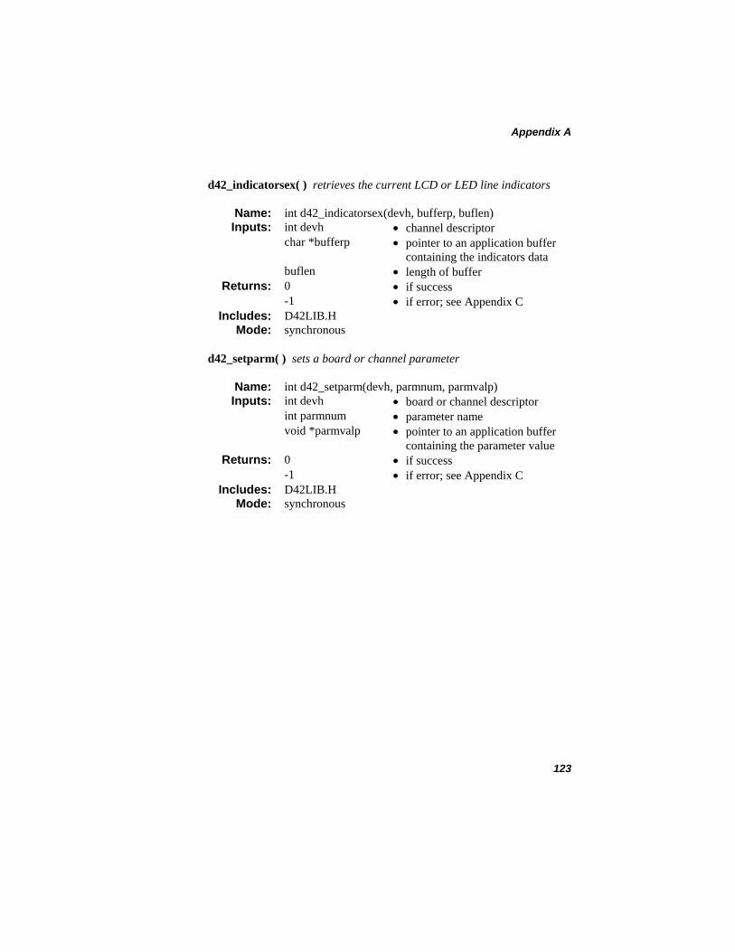
Appendix A
d42_indicatorsex( ) retrieves the current LCD or LED line indicators
int d42_indicatorsex(devh, bufferp, buflen) Name: Inputs: int devh • channel descriptor
char *bufferp • pointer to an application buffer containing the indicators data
buflen • length of buffer Returns: 0 • if success
-1 • if error; see Appendix C D42LIB.H Includes: synchronous Mode:
d42_setparm( ) sets a board or channel parameter
int d42_setparm(devh, parmnum, parmvalp) Name: Inputs: int devh • board or channel descriptor
int parmnum • parameter name void *parmvalp • pointer to an application buffer
containing the parameter value Returns: 0 • if success
-1 • if error; see Appendix C D42LIB.H Includes: synchronous Mode:
123

Dialogic® PBX Integration Software Reference
124

Appendix B Demonstration Programs for Windows®
This appendix provides instructions for running the Dialogic® D/42 Demonstration Program and the Siemens Optiset MWI Demo for Windows®. The D/42 program demonstrates the Dialogic® Unified API functions using the Dialogic® PBX Integration Board. The Siemens Optiset Demo may only be used with the Siemens Hicom 150 PBX to test MWI functionality.
CAUTION
The D42 demo works only with up to three boards in a system. An access violation occurs after a fourth Dialogic® D/82JCT-U or Dialogic® D/42x Board is added. Do not attempt to run the demo
with more than three boards in a system.
Documentation Conventions
The following conventions and terminology are used throughout the instructions contained in this section:
• Window titles are in italics. • Menu items are in bold. • The extension used to call the board channel is called Phone A. • The extension used receive the transfer is called Phone B.
Dialogic® D/42 Demo Basic operations performed by the Dialogic® PBX Integration Board include:
• answer • dial • supervised/blind transfer • play/record messages
125

Dialogic® PBX Integration Software Reference
D/42 Demo Requirements
• Two phones connected to a PBX • One Dialogic® PBX Integration Board connected to a PBX • The PBX must be configured according to the Dialogic PBX
Integration Board User’s Guide. ®
Setup
Before running the demonstration program, perform the following procedures:
1. Connect 1 channel of your board to an extension of the PBX.
2. Connect two telephones to two extensions of the PBX.
3. If necessary, start the board using the Dialogic® Configuration Manager (DCM).
Running the Demo
To run the demonstration program:
1. Go to the c:\program files\dialogic\samples\d42 directory or use the Start Menu on Windows®.
2. Start the D/42 Series Demonstration Program by double-clicking on d42demo.exe or by making appropriate selection from the Start Menu.
3. The Dialogic D/42 Demo window opens, as seen in Figure 19.
126

Appendix B
Figure 19. Dialogic D42 Demo Window
4. From the Options menu, choose Properties. The D42 Options window is displayed, as shown in Figure 20.
Figure 20. D42 Options Window
5. Enter the number of extension digits that corresponds to your PBX configuration.
127

Dialogic® PBX Integration Software Reference
NOTE: If this option is not set correctly, the demo program will not perform transfers correctly.
6. If you want to use supervised transfers, check the Supervised Transfers box.
NOTE: In a supervised transfer, the demo program puts the incoming call (Phone A) on hold and attempts to establish a connection with Phone B before the transfer is completed.
In a non-supervised, or blind transfer, the incoming call (Phone A) is transferred immediately to Phone B. You will hear the ring signal, and the D/42-xx channel is ready to accept a new call (indicators are gray).
7. From the Options Menu choose Input Strings. The Input Strings window will be displayed as shown in Figure 21.
128

Appendix B
Figure 21. Input Strings
8. Enter the strings for Dial, Cancel, and Complete fields for the PBX that is currently being used.
NOTES: 1. Use the $ (dollar) sign in place of ESC key while entering strings.
2. Certain default strings have been supplied for backwards compatibility. You must verify their correctness for the PBX that is currently being used with the demo. The $ (dollar) sign in the default strings indicates the ESC key.
129

Dialogic® PBX Integration Software Reference
9. Press OK to save and close the Input Strings window.
NOTE: If you skip setting up the Input Strings, you are prompted to enter them again at the time of opening the channels, as shown in Figure 22.
Figure 22. Input Strings Warning
10. Press OK to close the D42 Options window.
11. From the File menu, choose Open. The Select Your D42 Channel window displays, as shown in Figure 23.
Figure 23. Select Your D42 Channel
12. Choose a board listed below the applicable PBX Integration Board (Example: dxxxB1 under the Northern Telecom Norstar). A channel list is displayed in the right-hand window, as seen in Figure 24.
130

Appendix B
Figure 24. Select Your D42 Channel, Channel List Displayed
13. Choose a channel connected to the PBX and press OK (Example: dxxxB1C1). A window is displayed that simulates the appropriate phone set for your PBX. See Figure 25 for an example.
NOTE: All four channels are displayed, not just the channel connected to the PBX.
131

Dialogic® PBX Integration Software Reference
LED Indicators
LED Indicators
Display
Message WaitingIndicator
Message WaitingIndicator
Display
CALL WAITING
Application StatusMessages
Figure 25. ROLMphone Window on the D42 Demo
132

Appendix B
14. Observe that the date and time appear in the display. This verifies that the board is communicating with the PBX. If the date and time do not appear, verify that the correct channel is selected and that the phone line is connected to the proper channel on the board.
15. From Phone A, dial the number of the extension connected to the board channel selected in step 13.
16. Listen to the greeting.
17. Enter the extension for Phone B.
NOTE: If you do not enter an extension within five seconds, the demo plays the message, “Thank you for calling Dialogic Corporation” and hangs up.
18. When Phone B rings, answer the call.
NOTE: If the demo is performing a supervised transfer, the transfer completes immediately after voice is detected on the “transfer to” extension, or after 30 seconds of silence.
If performing a blind transfer, the transfer is completed immediately.
19. Observe the indicators, display, caller ID, and status areas in the demo window.
• Indicators - refer to Table 15 • Display - shows information sent from the PBX • Caller ID - shows the caller ID data sent by the PBX • Message Waiting Indicator (MWI) - turns on when a message is
recorded • Status Area - shows demo application status messages (e.g.,
dialing, ready, playing intro prompt, and message access code)
133

Dialogic® PBX Integration Software Reference
Table 15. Demo Indicator Definitions
Indicator Color M3710*
gray off green on red flash, hold
* Refer to Section 3, d42_indicators( ), for detailed description of the indicators.
20. You may repeat steps 15 through 19 using different scenarios for the Phone B (e.g., busy, no answer, forward).
NOTE: If you choose busy or no answer, you are prompted to leave a message. Recording stops when silence is detected. When you leave a message, the MWI turns on. Only one message is saved (any previously recorded message is overwritten). The saved message is deleted when the channel is closed.
To listen to the message, call back the extension and press the # key. The access number is displayed in the status area.
21. To close the open channel, choose Close from the File menu.
22. To exit the program, choose Exit from the File menu.
23. You may also choose to run one of the voice demo programs to check the voice functions of the board. Refer to the voice demos that are included in your Dialogic® System Release Software.
134

Appendix B
Siemens Optiset MWI Demo
The Siemens Optiset Message Waiting Indicator (MWI) demo turns a MWI light on and off by sending the appropriate Siemens Hicom 150 PBX switch commands. Note that this demo cannot be used with the Siemens Hicom 300. The MWI light can be toggled on and off by sending and deleting messages for a given extension.
This demo program follows the Siemens Optiset E phone key strokes for sending and deleting messages. An application program accomplishes this by sending the appropriate command escape sequences. The Siemens switch associates these commands with the key strokes required to accomplish sending and deleting messages. The demo program’s algorithm can be used in an application as is, or it can be modified to accomplish other tasks, as detailed in the Siemens manuals. The algorithm shows the basic approach needed to send command escape sequences to the Siemens Hicom 150. The switch “sees” the voice board with an appropriate application as an Optiset E phone and expects the correct key strokes to accomplish tasks.
The demo provides the user with three options:
• Open channels on a voice board • Send a message to a selected extension • Delete a selected message
To run the Siemens Optiset MWI Demo:
1. Go to c:\program files\dialogic\samples\Siemens Optiset Demo\debug directory.
2. Start the demo by double-clicking on mwi.exe.
135

Dialogic® PBX Integration Software Reference
3. The Dialogic Siemens Optiset MWI Demo window opens, as seen in Figure 26.
Figure 26. Siemens Optiset MWI Demo Window
4. From the Options menu, choose Select Channel. The Enter Channel Number pop-up is displayed, as shown in Figure 27.
Figure 27. Enter Channel Number
5. Enter the channel number that corresponds to your PBX configuration and choose OK.
136

Appendix B
6. If the channel opens, the Siemens Optiset MWI Demo window displays a success message as shown in Figure 28.
Figure 28. Channel Opened Message
7. From the Options menu, choose Send Message. The Send Message pop-up is displayed, as shown in Figure 29.
Figure 29. Send Message
8. Enter an extension applicable to your PBX setup and choose OK.
137

Dialogic® PBX Integration Software Reference
9. If the send is successful, the pop-up shown in Figure 30 appears.
Figure 30. Message Sent
10. From the Options menu, choose Delete Message. The Delete Message pop-up is displayed, as shown in Figure 31.
Figure 31. Delete Message
11. Choose OK. Use the Next button if more than one message was sent.
12. If the delete is successful, the pop-up shown in Figure 32 appears.
Figure 32. Message Deleted
138

Appendix C Error Definitions Error Code Name Return
Value Description
ED42_NOERROR 0x0000 Operation completed ED42_NOTIMP 0x0500 Function is not
implemented ED42_MAXCHAN 0x0501 Maximum channel
capacity reached ED42_INVALARG 0x0502 Illegal argument in
function ED42_BADPARM 0x0503 Invalid value for
parameter ED42_UNSUPPORTED 0x0504 Unsupported feature ED42_RDFWVER 0x0505 Error reading firmware
version ED42_UNKNOWNBOARD 0x0506 Unknown board type ED42_BADDEVICE 0x0507 Invalid or wrong device
handle ED42_DLLINIT 0x0508 Unable to initialize DLL ED42_SYSTEM 0x0509 System error ED42_NOCOMM 0x050A No communication with
switch ED42_NOTIDLE 0x050B Device is not idle ED42_FEATSESSIONALREADYOPEN
0x050C Feature session is already open
ED42_NOFEATURESESSION 0x050D No feature session available
ED42_FWREQFAILURE 0x050E Firmware request failed ED42_MEMORY 0x050F Buffer is too small
139
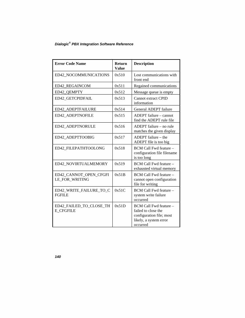
Dialogic® PBX Integration Software Reference
Error Code Name Return Value
Description
ED42_NOCOMMUNICATIONS 0x510 Lost communications with front end
ED42_REGAINCOM 0x511 Regained communications ED42_QEMPTY 0x512 Message queue is empty ED42_GETCPIDFAIL 0x513 Cannot extract CPID
information ED42_ADEPTFAILURE 0x514 General ADEPT failure ED42_ADEPTNOFILE 0x515 ADEPT failure – cannot
find the ADEPT rule file ED42_ADEPTNORULE 0x516 ADEPT failure – no rule
matches the given display ED42_ADEPTTOOBIG 0x517 ADEPT failure – the
ADEPT file is too big ED42_FILEPATHTOOLONG 0x518 BCM Call Fwd feature –
configuration file filename is too long
ED42_NOVIRTUALMEMORY 0x519 BCM Call Fwd feature – exhausted virtual memory
ED42_CANNOT_OPEN_CFGFILE_FOR_WRITING
0x51B BCM Call Fwd feature – cannot open configuration file for writing
ED42_WRITE_FAILURE_TO_CFGFILE
0x51C BCM Call Fwd feature – system write failure occurred
ED42_FAILED_TO_CLOSE_THE_CFGFILE
0x51D BCM Call Fwd feature – failed to close the configuration file; most likely, a system error occurred
140

Appendix C
141
Error Code Name Return Value
Description
ED42_CANNOT_OPEN_CFGFILE_FOR_READING
0x51E BCM Call Fwd feature – failed to open the configuration file for reading
ED42_FAILED_TO_READ_CFGFILE
0x51F BCM Call Fwd feature – a system read failure occurred
ED42_CORRUPT_CFG_FILE 0x520 BCM Call Fwd feature – missing mandatory fields


Appendix D Asynchronous Event Definitions Event Code Name
Return Value
Description
TD42_ASYNCCHSTATUS 0x00D0 Asynchronous channel status notification
TD42_ASYNCCLOSEFEATSESSION 0x00D5 Asynchronous close of feature session (NS only)
TD42_ASYNCDISP 0x00DA Asynchronous display notification
TD42_ASYNCLINE 0x00DB Asynchronous line status change notification
TD42_SOFTKEYINPUT 0x00D2 Soft key pressed (NS only)
TDX_ERROR 0x0089 Asynchronous error message
When using the above event data in sample applications, the following information is applicable:
• For TD42_ASYNCCHSTATUS: sr_getevtdatap( ) returns a pointer to an unsigned short containing the status of the channel.
• For TD42_ASYNCDISP: sr_getevtdatap( ) returns a pointer to a null-terminated buffer containing the display. sr_getevtlen( ) returns the length of the data.
• For TD42_ASYNCLINE: sr_getevtdatap( ) returns a pointer to a LINEINDICATOR structure containing the status of the indicator. The structure is defined in the d42lib.h and contains two members: line (the line #) and status (the status).
143

Dialogic® PBX Integration Software Reference
144
Glossary
Adaptive Differential Pulse Code Modulation (ADPCM): A technique for reducing voice data storage requirements used on voice boards. With ADPCM, rather than store the value of the speech sample (i.e., all 8 bits), only the change in the signal level between the present and the previous sample is stored. Fewer bits are needed to describe the change from one sample to the next because voice signals vary relatively slowly.
ADPCM: See Adaptive Differential Pulse Code Modulation.
analog: 1. A method of telephony transmission in which the information from the source (for example, speech in a human conversation) is converted into an electrical signal that varies continuously over a range of amplitude values. 2. Used to refer to applications that use loop start signaling instead of digital signaling.
answer supervision: A telephone system feature that returns a momentary drop in loop current when a connection has been established. When call progress analysis detects a transient loop current drop, it returns a connect event.
base address: A starting memory location (address) from which other addresses are referenced.
buffer: A block of memory or temporary storage device that holds data until it can be processed. It is used to compensate for the difference in the rate of flow of information (or time occurrence of events) when transmitting data from one device to another.
bus: An electronic path that allows communication between multiple points or devices in a system.
called/calling number ID: A PBX feature that identifies the number of the calling party to the extension that is called.
call progress analysis: A voice software feature that monitors the progress of an out-bound call by detecting the different results that can occur after dialing, which allows you to process the call based on the outcome. By using call progress analysis, you can determine whether
145

Dialogic® PBX Integration Software Reference
the line is answered, the line rings but is not answered, the line is busy, or there is a problem in completing the call.
central office (CO): The telephone company (informally). A local telephone switching exchange.
channel: A voice I/O port on a voice board. 1. When used in reference to an analog board, an audio path, or the activity happening on that audio path (for example, in “the channel goes off-hook”). 2. When used in reference to a digital board, a data path, or the activity happening on that data path. 3. When used in reference to a bus, an electrical circuit carrying control information and data.
class of service (COS): A defined group of features. Once an extension is assigned to a COS, the COS determines which features may be accessed by that extension.
computer telephony: The extension of computer-based intelligence and processing over the telephone network to a telephone. Lets you interact with computer databases or applications from a telephone and also enables computer-based applications to access the telephone network. Computer telephony makes computer-based information readily available over the world-wide telephone network from your telephone. Computer telephony technology incorporated into PCs supports applications such as: automatic call processing; automatic speech recognition; text-to-speech conversion for information-on-demand; call switching and conferencing; unified messaging that lets you access or transmit voice, fax, and E-mail messages from a single point; voice mail and voice messaging; fax systems including fax broadcasting, fax mailboxes, fax-on-demand, and fax gateways; transaction processing such as Audiotex and Pay-Per-Call information systems; call centers handling a large number of agents or telephone operators for processing requests for products, services or information; etc.
configuration file: A file used to download voice hardware and software specifications to a voice board.
connect: A call progress analysis event indicating that the call has been answered. A connect can be established by cadence detection, loop current detection, or positive voice detection.
D/4x: A general term used to refer to 4-channel Dialogic® Voice Boards (e.g., Dialogic® D/41D, D/41E, and D/41ESC Voice Boards).
146

Glossary
D/xxx: A general term used to refer to all models of Dialogic® Voice Boards.
D40CHK: The Dialogic® diagnostic program that is used to test voice boards for hardware problems.
digit queue: The location where digits are stored after they are detected. Digits are processed on a first-in, first-out basis, and can be accessed by the getdtmfs( ) function.
disconnect supervision: A feature that detects and acts on the change in electrical state from off-hook to on-hook.
driver: A software module that provides a defined interface between a program and the hardware. It directly controls the data transfer to and from I/O.
DSP: 1. Digital signal processor. A specialized microprocessor designed to perform speedy and complex operations with digital signals. 2. Digital signal processing.
DTMF: Dual Tone Multi Frequency. 1. A signaling method. 2. The tone made by pressing a button on a push-button telephone. This tone is actually the combination of two tones, one high frequency and one low frequency.
event: 1. A specific activity that has occurred on a channel. The voice driver reports channel activity to the application program in the form of events, which allows a program to identify and respond to a specific occurrence on a channel. Events provide feedback on the progress and completion of functions, and indicate the occurrence of other channel activities. Events are sometimes referred to in general as termination events, because most of them indicate the end of an operation. 2. Any signal or condition that causes a state transition in a state machine, the majority of which are usually the physical events produced by the voice driver.
Event Block (EVTBLK): A data structure that is used as output for the gtevtblk( ) function. The gtevtblk( ) function removes an event from the queue and places it into an EVTBLK for use by the application program.
FCC: Federal Communications Commission. The governing body for communications regulations within the U.S.
147

Dialogic® PBX Integration Software Reference
firmware: Software downloaded to a board and stored in semi-permanent memory.
flash: A signal that consists of a momentary off-hook/on-hook/off-hook transition that is most often used by a voice board to alert a telephone switch. This signal usually initiates a call transfer. The dial( ) function can generate a hook flash by including the flash character in the dial string.
hook flash: See flash.
hook switch: The name given to the circuitry that controls on-hook and off-hook state of a voice board telephone interface.
idle: The channel state when no multitasking function is in operation on the channel. The opposite of busy.
IRQ: Interrupt request. A signal sent to a central processing unit (CPU) to temporarily suspend normal processing and transfer control to an interrupt handling routine. Interrupts may be generated by conditions such as completion of an I/O process and detection of an event.
loop current: The current that flows through the circuit from the telephone switch to a voice board when a channel is off-hook.
loop start: In an analog environment, an electrical circuit consisting of two wires (or leads) called tip and ring, which are the two conductors of a telephone cable pair. The CO provides a voltage (called “talk battery” or just “battery”) to power the line. When the circuit is complete, this voltage produces a current called loop-current. The circuit provides a method of starting (seizing) a telephone line or trunk by sending a supervisory signal (going off-hook) to the CO.
multitasking functions: Functions that allow voice software to perform concurrent operations. After being initiated, multitasking functions return control to the program so that during the time it takes a function to complete, the application program can perform other operations, such as initiating a function on another channel.
no answer: A call progress analysis event indicating that the call has not been answered. A no answer event is returned after a ring cadence has been established by cadence detection and there was no break in the ring cadence for a specified number of times.
148

Glossary
no ringback: A call progress analysis event indicating that there is a problem in completing the call. Cadence detection has determined that the signal is continuous silence or nonsilence.
nonsilence: Sound. Used when describing an audio cadence.
off-hook signal: A basic signal used on the telephone network that is produced when the line loop between the telephone set and the central office switch is closed and loop current flows, which also powers the telephone. This term is derived from the position of the old fashioned telephone set receiver in relation to the mounting hook provided for it.
on-hook signal: A basic signal used on the telephone network that is produced when the line loop between the telephone set and the central office (CO) switch is open and no loop current flows. This term is derived from the position of the old fashioned telephone set receiver in relation to the mounting hook provided for it.
ring detect: The act of sensing that an incoming call is present by determining that the telephone switch is providing a ringing signal to a voice board.
SCbus : Signal Computing Bus. A high-speed serial TDM (time division multiplexed) bus designed for connecting devices in telecommunications and computer systems. SCbus enables computer telephony hardware of multiple kinds from multiple vendors to be integrated within richly capable computer telephony systems. For instance, up to eight PBX integration boards can be connected up over an SCbus using a card-to-card ribbon cable. It supports up to 2048 bi-directional time slots, clocking, and an optional HDLC messaging channel, which can be used for signaling.
signaling: The transmission of electrical signals on the telephone network. The Dialogic® voice software supports the following signaling methods: DTMF, MF, R2 MF, Socotel, Global Tone Detection and Generation, and Dial Pulse Detection and Generation.
standard voice driver See voice driver.
system events: Events in a state machine that are generated by relevant system signals, such as keyboard input, communications adapters, etc. These generally cause state changes for all channels rather than a specific channel.
149

Dialogic® PBX Integration Software Reference
talk off: The false tripping of DTMF receivers caused by speech.
telephone switch: A telephone company central office or a PBX (private branch exchange).
termination condition: A requirement that, when met, causes a multitasking function to terminate. You can enable the termination conditions by setting parameters in the Read/Write Block (RWB) and then passing the RWB as one of the function parameters. The termination conditions are monitored while the multitasking function is in progress. The function continues to execute until one of the selected termination conditions has been met. When the function terminates, an event is produced, indicating which termination condition caused the function to terminate.
tone event: A tone-on or tone-off event that is produced by global tone detection when a GTD tone is detected. A tone event can be accessed on the event queue by using the gtevtblk( ) function, which provides the channel, event code, and GTD tone ID.
Unified API: . This Dialogic® API provides a single set of basic, high-level calls that can be used for any supported switches and are sent directly to the switch through the Dialogic® PBX Integration Board, without additional hardware. Functioning as an extension to the Dialogic®
Voice API, the Unified API offers a single design model that is flexible enough to allow developers to take advantage of advanced PBX features (such as called/calling number ID and ASCII display information).
voice demonstration programs: The programs that are included with the Dialogic® voice software and which demonstrate voice software features; provided in both source code and executable formats.
voice driver: The device driver for the Dialogic® voice boards; D40DRV.EXE. Executes as a terminate-and-stay-resident (TSR) program.
voice hardware diagnostic programs: The D40CHK.EXE and D41ECHK.EXE programs allow you to test the features of the Dialogic® voice hardware.
150

Glossary
voice library: A C language function library that can be accessed from assembly language programs or from applications written in a high-level language.
voice processing: Features of the voice software that provide the ability to record and play voice messages.
voice software: The Dialogic® Voice Development Package software, which includes the Voice Installation Programs and Files, Voice Demonstration Programs and Files, Voice Library (C Language Functions), and Voice Driver.
voice store-and-forward: A term used to refer to a voice mail system. An early term for voice processing.
wink: A signal that consists of a momentary on-hook/off-hook/on-hook transition, which is used by a voice board as an acknowledgment signal. The wink( ) function generates an out-bound wink on a channel in response to an incoming call.
151

Dialogic® PBX Integration Software Reference
152

Index
d42_indicatorsex( ), 67 A d42_setparm( ), 71, 123 Asynchronous Event Definitions, 143 D4BD_ GETSWITCHTYPE, 40 ATD4_BDTYPE( ), 20, 119 D4BD_CALLID, 40, 72 ATD4_CHTYPE( ), 22, 119 D4CH_CHANNELSTATUS, 40, 72 C Demo Indicator Definitions, 134
Call Progress Analysis, 9, 15, 77, 114, 145 dial programmable keys, 76, 82
Avaya, 82 Event, 146, 148, 149 MITEL SUPERSET 400 Series, 98
call transfer, 16, 76, 114, 148 Nortel M2616, 107 Nortel M7324, 104 called/calling number ID, 15, 16, 46, 47,
115, 118, 122, 145, 150 Siemens Optiset, 92 Siemens ROLMphone, 89
converting existing applications, 118 disconnect supervision, 117
D dollar sign, 129 D/42 Demo, 126 dx_dial( ), 118 D/42 driver, 11, 16 E D/82JCT-U hardware installation, 12
Error Definitions, 139 d42_brdstatus( ), 24, 119
G d42_chnstatus( ), 26, 120 Global Tone Detection, 114 d42_dial( ), 28, 120
I d42_display( ), 31, 120
in-band signaling, 115 d42_displayex( ), 35, 121 NEC, 113
d42_getparm( ), 39, 121 indicators, 52
d42_getver( ), 43, 121 Avaya, 49, 53 MITEL SX SUPERSET 400 Series,
61 d42_gtcallid( ), 46, 122
d42_gtcallidex( ), 49 Nortel Meridan 1 M2616, 64 Nortel Norstar M7324, 62, 67 d42_indicators( ), 52, 122, 123 Siemens Hicom, 59
153

Dialogic® PBX Integration Software Reference
Siemens ROLM, 57 U indicatorsex, 67 Unified API, 11, 15, 16, 19, 150 input strings, 130 V installation
voice and call processing, 10 D/82JCT-U hardware, 12 System Release software, 12
N NEC
in-band signaling, 113 out-of-band signaling, 113
O opening a D/82JCT-U channel, 75
out-of-band signaling, 115 Avaya Definity 75, 85 Avaya Definity G3, 88 MITEL Definity G3, 100, 103 NEC, 113 Nortel Meridian 1, 109 Nortel Norstar, 104, 106 Siemens Hicom, 94, 97 Siemens ROLM, 91
P PBX configuration, 12
S Siemens Optiset Demo, 135
standard voice library, 9, 11, 15, 16
synchronous, 16
System Release Software installation, 12
T transfer. See call transfer
154