dialogic ip-media gateway installation and … ip-media gateway installation and configuration...
TRANSCRIPT

Dialogic IP-Media Gateway Installation and Configuration Integration Note
1. Scope This document is intended to detail a typical installation and configuration of a PBX IP-Media Gateway when used to interface between a PBX and a unified messaging type application. 2. Configuration Details Listed below are the specific details of the PBX and gateways used in the testing to construct the following documentation. 2.1 PBX PBX Vendor Mitel
Model(s) 3300
Software Version(s) 3300 Universal NSU - 50001270
Additional Notes N/A 2.2 Gateway Gateway Model TIMG300DTI
Software Version(s) 5.0.42
Protocol E1 QSIG 2.3 System Diagram The diagram below details the setup used in the testing and creation of the technical document.
PBX
Fax Subscriber Stations
TIMG
MessagingServer
T1/E1
IP LAN
1
2
3. Prerequisites 3.1 PBX Prerequisites PBX must have all supplemental service packages installed for the QSIG protocol to operate properly and provide all advanced supplemental services. 3.1.1 PBX Equipment Required To connect to the PBX using T1 QSIG you must use a 3300 Universal NSU - 50001270 line card. 3.1.2 PBX Cabling Requirements Cabling for QSIG connections must be CAT5e or better. Standard voice quality cable will not provide optimum signal quality and the gateway will have problems establishing connection on the D-Channel. 3.2 Gateway Prerequisites The gateway needs to support a E1 QSIG interface. 4. Summary of Limitations No limitations noted as of the last update to this document.
5. Gateway Setup Notes During the initial setup of the Dialogic gateway using the serial port you must:
• Assign the gateway a Unique IP address, subnet mask and network gateway address (if the latter is required).
• Configure the gateway to use the SIP VoIP protocol. • Set the Line Mode to E1. • Set the Protocol to ISDN - QSIG.
During the solution specific setup of the Dialogic gateway using the web interface you must:
• Configure the gateway with at least a single IP endpoint pointing to your voice server. • Configure your coder as either aLaw or uLaw as required. • Set the Voice coder to be either G7.11 (default) or G.273 if required. • Set the Line Encoding and Line Framing as required by your E1 Interface. Typical
settings are Encoding = HDB3 and Framing = CRC_MF. 6. PBX Setup Notes The basic steps of setting up the PBX for use with this gateway and a voice messaging system are as follows:
• Configuring the hardware and class of service. • Configuring the ISDN-PRI interface. • Configuring ARS options. • Setting up subscriber station sets.
All PBX programming is done via a web browser by connecting to the network port of the PBX.
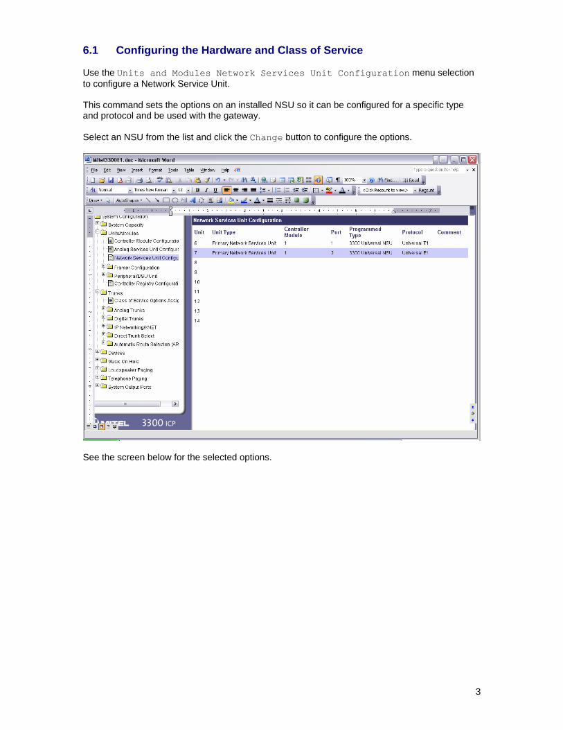
6.1 Configuring the Hardware and Class of Service Use the Units and Modules Network Services Unit Configuration menu selection to configure a Network Service Unit. This command sets the options on an installed NSU so it can be configured for a specific type and protocol and be used with the gateway. Select an NSU from the list and click the Change button to configure the options.
See the screen below for the selected options.
3
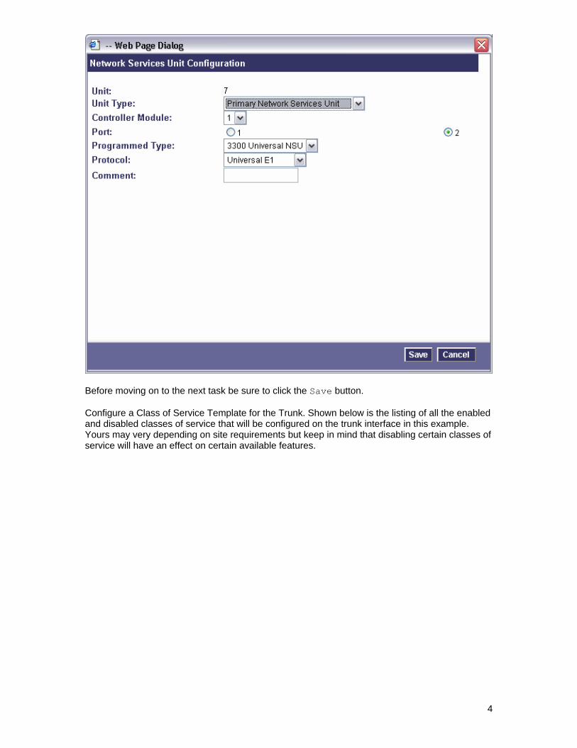
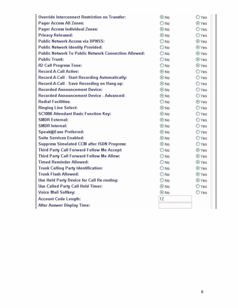
Before moving on to the next task be sure to click the Save button. Configure a Class of Service Template for the Trunk. Shown below is the listing of all the enabled and disabled classes of service that will be configured on the trunk interface in this example. Yours may very depending on site requirements but keep in mind that disabling certain classes of service will have an effect on certain available features.
4

5

6

7
8

9

Before moving on to the next task be sure to click the Save button. 6.2 Configuring the ISDN-PRI Interface Use the ISDN PRI Link Descriptor Assignment menu selection to build a template that sets the various options for a trunk interface such as framing, coding and interface type. Use the Add or Change buttons to either build a new Link Descriptor or modify an existing Link Descriptor.
See the screen below for the selected options.
10
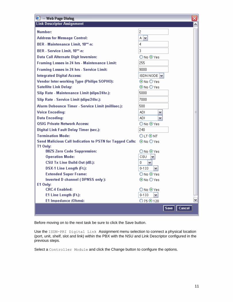
Before moving on to the next task be sure to click the Save button. Use the ISDN-PRI Digital Link Assignment menu selection to connect a physical location (port, unit, shelf, slot and link) within the PBX with the NSU and Link Descriptor configured in the previous steps. Select a Controller Module and click the Change button to configure the options.
11
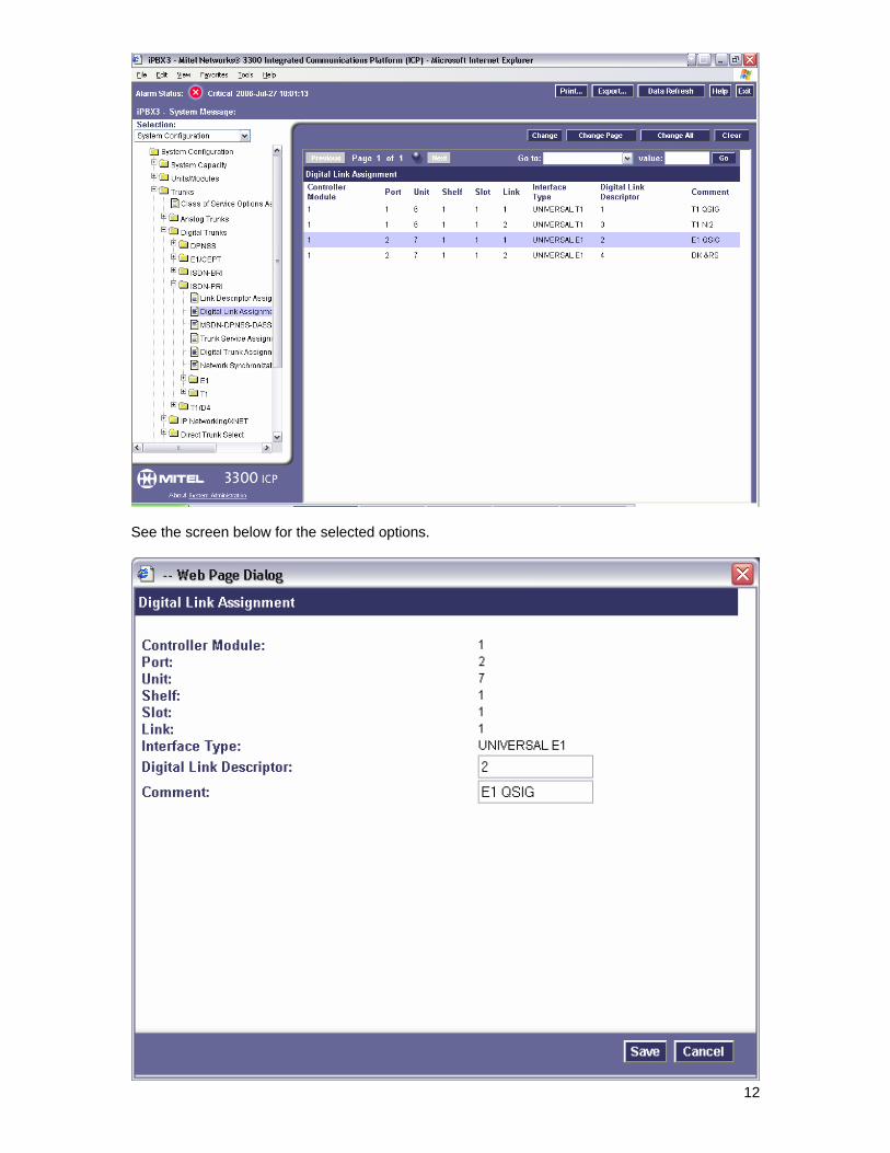
See the screen below for the selected options.
12

Before moving on to the next task be sure to click the Save button. Use the ISDN-PRI MSDN-DPNSS-DASSII Trunk Circuit Descriptor menu selection to assign direction and protocols to the individual trunk cards in the PBX. Select a trunk number and click the Change button to configure the options.
See the screen below for the selected options.
13
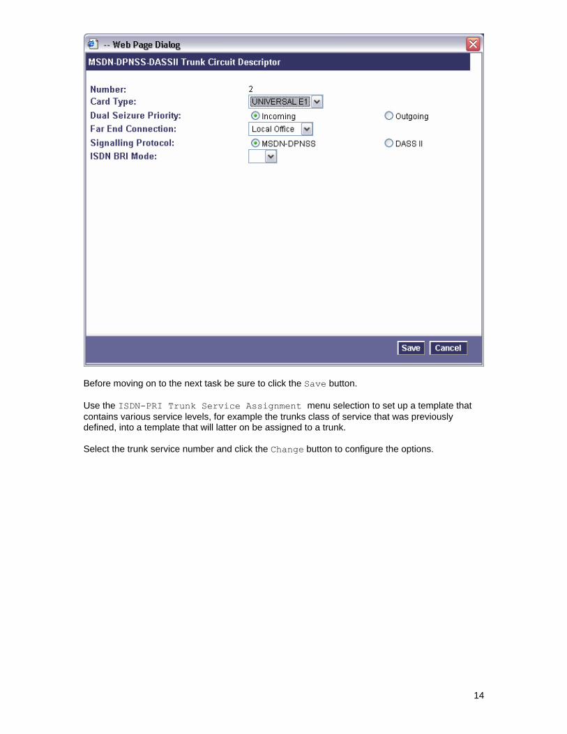
Before moving on to the next task be sure to click the Save button. Use the ISDN-PRI Trunk Service Assignment menu selection to set up a template that contains various service levels, for example the trunks class of service that was previously defined, into a template that will latter on be assigned to a trunk. Select the trunk service number and click the Change button to configure the options.
14

See the screen below for the selected options.
15

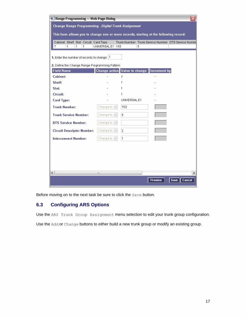
Before moving on to the next task be sure to click the Save button. Use the ISDN-PRI Digital Trunk Assignment menu selection to configure the individual trunk members and assign them the defined Trunk Service Assignment template and Trunk Circuit Descriptor template that were configured in the previous steps. This gets done for each member of a trunk interface. Select each individual trunk member and click the Change button to configure the options.
See the screen below for the selected options.
16
Before moving on to the next task be sure to click the Save button. 6.3 Configuring ARS Options Use the ARS Trunk Group Assignment menu selection to edit your trunk group configuration. Use the Add or Change buttons to either build a new trunk group or modify an existing group.
17

See the screen below for the selected options.
Click the Save button when you are finished editing the options and wish to save your configuration. When you have configured a trunk group you use the Add Member button to add individual trunk members to the group.
18

Before moving on to the next task be sure to click the Save button. Use the ARS Route Assignment menu selection to define a route to direct calls to a specific trunk. Select a Route Number and click the Change button to configure the options.
See the screen below for the selected options.
19
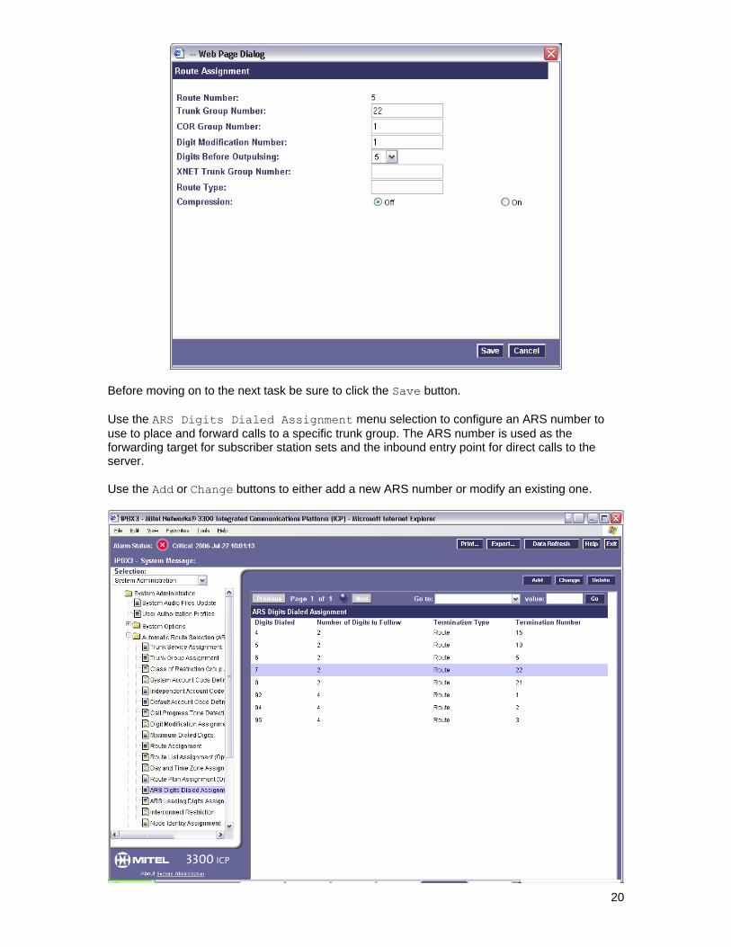
Before moving on to the next task be sure to click the Save button. Use the ARS Digits Dialed Assignment menu selection to configure an ARS number to use to place and forward calls to a specific trunk group. The ARS number is used as the forwarding target for subscriber station sets and the inbound entry point for direct calls to the server. Use the Add or Change buttons to either add a new ARS number or modify an existing one.
20

This example shows setting up ARS to except any 3 digit number that starts with a 7 as a dialable number. The ASR table will then take the call and route it to trunk group 22. Useable numbers in this example would be any number between 700 and 799 all inclusive. An alternate method of configuration would be to define a very specific number, for example 700, not an entire range, and not define any following digits. The method you choose is up to what your sites configuration will support. See the screen below for the selected options.
Below is an example of the configuration using the described alternate method.
Before moving on to the next task be sure to click the Save button.
21
22
6.4 Setting Up Subscriber Station Sets There is no PBX side programming for setting up the subscriber station sets. All the forwarding of the subscriber station sets is defined directly on subscriber station set using the phones soft menu keys. Subscribers should be directed to set their internal and external ring no answer and busy forwarding conditions to the Pilot Number setting defined in the hunt group configuration. 6.5 Additional Comments Ensure no Node Identity assignment has been entered. If this is entered it will append extra digits onto extensions as they pass across the trunk to the gateway. 7. Testing Validation Matrix The table below shows various test scenarios that are run as typical validation scenarios when the gateway is used in a voice messaging situation. The notes column specifies any notable parts of the test. The test scenarios below assume that all gateway configuration parameters are at their default values. For a complete sample showing call flows and states please consult the Gateway SIP Compatibility Guide. Test Number
Call Scenario Description Notes
Inbound call scenarios
1 Direct call to hunt group. The calling party number is expected to be contained in the From header of the Invite.
2 Internal ring-no-answer forward. The called party will be shown in the Diversion header of the invite. The calling party will be contained in the From header. The reason of the diversion header is shown as no-answer.
3 External ring-no-answer forward. The called party will be shown in the Diversion header of the invite. The calling party (if available) will be contained in the From header. The reason of the diversion is shown as no-answer.
4 Internal busy forward from a subscribers station set.
The called party will be shown in the Diversion header of the invite. The calling party will be contained in the From header. The reason of the diversion header is shown as busy.
5 External busy forward from a subscribers station set.
The called party will be shown in the Diversion header of the invite. The calling party will be contained in the From header. The reason of the diversion header is shown as busy.
6 Internal all call forward from a subscribers station set.
The called party will be shown in the Diversion header of the invite. The calling

23
party will be contained in the From header. The reason of the diversion header is shown as fwd-all.
7 External all call forward from a subscribers station set.
The called party will be shown in the Diversion header of the invite. The calling party will be contained in the From header. The reason of the diversion header is shown as fwd-all.
Transfer Scenarios
8 Blind transfer to a station from messaging server where the destination answers the call.
The transfer is completed once the destination is judged as connected. Depending upon the speed that the destination is answered the caller and called parties may be connected together with a slight bit of the called parties voice clipped.
9 Blind transfer to a station from messaging server where the destination does not answer the call.
If the station is configured to forward back to the gateway then the call will arrive looking as a forwarded call with the called party being the transfer destination but the calling party may be the gateway port performing the transfer, depending on how quickly the transfer to the destination can be completed.
10 Blind transfer to a subscribers station from messaging server where the destination is busy.
The transfer should fail.
11 Blind transfer to an invalid number. The transfer should fail.
12 Supervised transfer to a subscribers station from messaging server where the user does not answer the call.
The transfer completion speed and timing is up to the application. The application should decide to either complete the transfer and let the stations forwarding carry it back to the gateway or abort it before the forwarding happens.
13 Supervised transfer to a subscribers station from messaging server where the user answers the call.
The transfer completion speed and timing is up to the application.
13 Supervised transfer to a subscribers station from messaging server where the destination is busy.
The transfer completion speed and timing is up to the application. The application should decide to either complete the transfer and let the stations forwarding carry it back to the gateway or abort it before the forwarding happens.
14 Supervised transfer to an Invalid number.
The transfer completion speed and timing is up to the application.
Outbound Call Scenarios

24
15 Outbound call to subscriber station that answers.
The call is flagged to the application as completed when the gateway can determine that the call has been connected through. The application should take this into account when making decision when to start the audio stream.
16 Outbound call to subscriber station that does not answer.
The application needs to take into account if the destination has been set to forward back to the gateway for a ring no answer condition and judge accordingly when to either stop waiting for an answer and cancel the call or know that it will end up arriving back to the gateway as a forwarded call.
17 Outbound call to subscriber station that is busy.
The application needs to take into account if the destination has been set to forward back to the gateway for a ring no answer condition and judge accordingly when to either cancel the call or know that it will end up arriving back to the gateway as a forwarded call.
18 Outbound call to an external number. Depending on the state of the destination the call will either be judged as connected or fail do to busy or error tone conditions.
MWI Scenarios
19 Turn a subscribers light on that is currently off.
This should return success.
20 Turn a subscribers light on that is currently on.
This should return success.
21 Turn a subscribers light off that is currently on.
This should return success.
22 Turn a subscribers light off that is currently off.
This should return success.
8. Troubleshooting 8.1 Important Debugging Tools
• Ethereal/Wireshark – Used to view and analyze the network captures provided by the Dialogic gateway diagnostic firmware.
• Adobe Audition -- Used to review and analyze the audio extracted from the network captures to troubleshoot any audio related issues.

25
8.2 Important Gateway Trace Masks These keys are helpful during all troubleshooting scenarios and should be considered keys to activate by default fro all troubleshooting cases.
• voip prot and voip code – this allows the collection of all SIP related messages as they are sent from and received by the gateway. This data is important in cases where you feel that the gateway is not able to communicate properly with the messaging server.
• tel event and tel code – This allows the collection of all circuit side activity of the emulated station set such as display updates, key presses, light transitions and hook state changes. This data is very important in the following scenarios:
o Call control problems (dropped calls, failing transfers, etc…) o Integration problems (incorrect mailbox placement, missed auto-attendant
greetings etc…)
• teldrv prot – This allows the collection of all ISDN messages both transmitted and received on the gateways front end interface. This data is very important in the following scenarios:
o Call control problems (dropped calls, failing transfers, etc…) o Integration problems (incorrect mailbox placement, missed auto-attendant
greetings etc…) These keys are helpful during specific issues and can be enabled for targeted troubleshooting of very specific cases. Activation of these keys may generate large amounts of data on busy systems and increase the size of the collected log files, but will not harm system performance.
• dspif (all keys) – This allows the collection of tone related data. This data is very helpful in cases where you think you have problems detection specific tones that should be, should not be, or are expected to be present at specific times during the call. If you do not suspect a tone related issues this key may be left disabled.
NOTE: Turning on all traces is not recommended. Doing this floods the debug stream with significant amounts of information that can cause delays in determining the root cause of a problem. 9. Appendix 9.1 Abbreviations LBRC Low Bit Rate Coder
MWI Message Waiting Indication
LWC Leave Word Calling
PBX Private Branch Exchange

26
For more details, go to www.dialogic.com. Dialogic Corporation 9800 Cavendish Blvd., 5th floor Montreal, Quebec CANADA H4M 2V9 © 2006 Dialogic Corporation. All rights reserved. Dialogic is a registered trademark of Dialogic Corporation. Dialogic's trademarks may be used publicly only with permission from Dialogic. Such permission may only be granted by Dialogic’s legal department at the address provided above. The names of actual companies and products mentioned herein are the trademarks of their respective owners. Dialogic encourages all users of its products to procure all necessary intellectual property licenses required to implement their concepts or applications, which licenses may vary from country to country. No licenses or warranties of any kind are provided under this document. Dialogic may make changes to specifications, product descriptions, and plans at any time, without notice. 05-2571-001 12/06