dial plans and routing - cisco cisco bts 10200 softswitch routing and dial plan guide, release 6.0.4...
TRANSCRIPT

Cisco BTS 10200 SoOL-24996-02
C H A P T E R 5
Dial Plans and RoutingRevised: May 14, 2012, OL-24996-02
IntroductionThis chapter provides detailed dial plan and routing information for the Cisco BTS 10200 Softswitch. The following subjects are discussed in this chapter:
• Originating Basic Call State Machine (CS2 Call Model)
• Cisco BTS 10200 Feature Server Strategy
• Point of Presence
• Network Configuration
• Subscriber Types
• Digit Collection
• Dial Plans
• Digit Manipulation
• Digit Analysis
• Class of Service Screening
• Routing
• Trunk Group Types
• Generic Address Parameter Based Routing
• Tandem Provisioning
• Local Toll-Free Service Provisioning
• Carriers and Service Providers
• Carrier Based Routing
• Call Processing Flow
Note When a customer is temporarily disconnected, all calls except 911 calls are routed to the customer support number.
5-1ftswitch Routing and Dial Plan Guide, Release 6.0.4
Chapter 5 Dial Plans and RoutingOriginating Basic Call State Machine (CS2 Call Model)
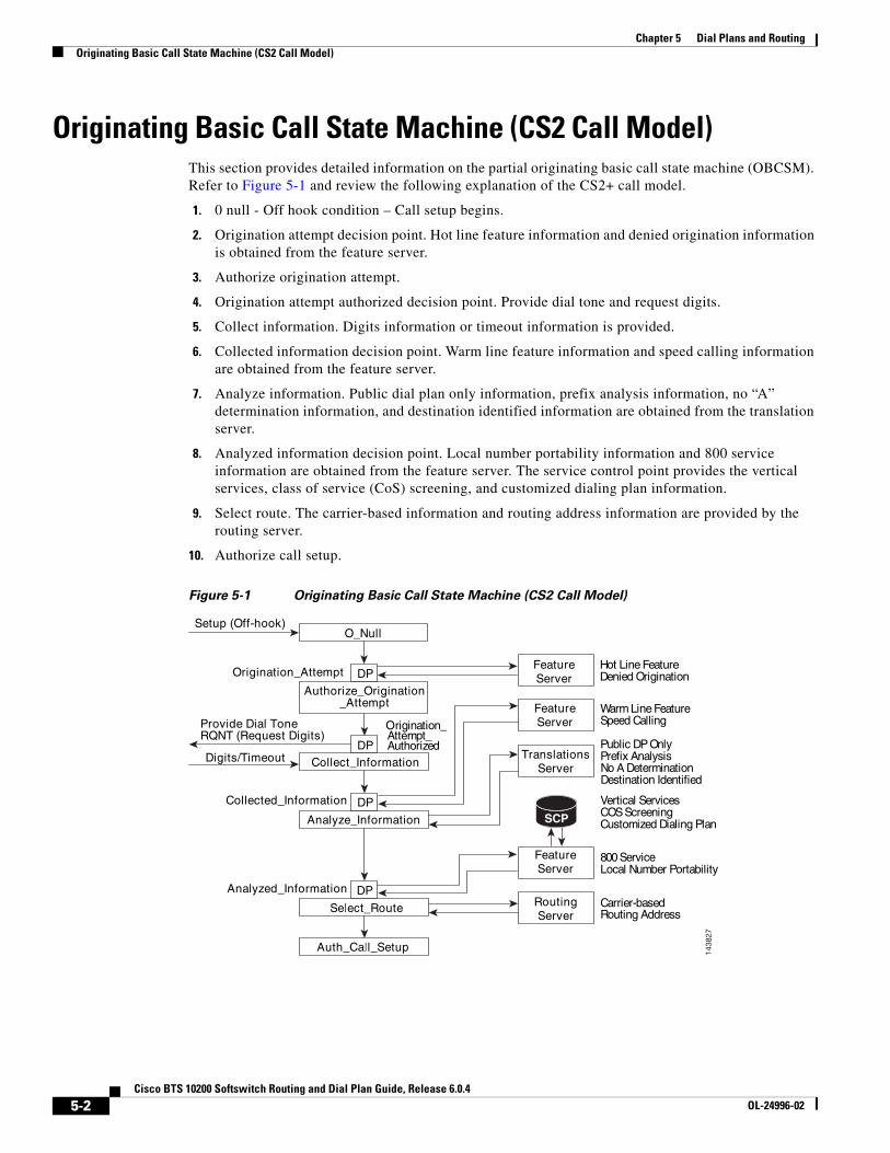
Originating Basic Call State Machine (CS2 Call Model)This section provides detailed information on the partial originating basic call state machine (OBCSM). Refer to Figure 5-1 and review the following explanation of the CS2+ call model.
1. 0 null - Off hook condition – Call setup begins.
2. Origination attempt decision point. Hot line feature information and denied origination information is obtained from the feature server.
3. Authorize origination attempt.
4. Origination attempt authorized decision point. Provide dial tone and request digits.
5. Collect information. Digits information or timeout information is provided.
6. Collected information decision point. Warm line feature information and speed calling information are obtained from the feature server.
7. Analyze information. Public dial plan only information, prefix analysis information, no “A” determination information, and destination identified information are obtained from the translation server.
8. Analyzed information decision point. Local number portability information and 800 service information are obtained from the feature server. The service control point provides the vertical services, class of service (CoS) screening, and customized dialing plan information.
9. Select route. The carrier-based information and routing address information are provided by the routing server.
10. Authorize call setup.
Figure 5-1 Originating Basic Call State Machine (CS2 Call Model)
1438
27
desab-reirraCoR nitu g dA sserd
ecivreS008ytilibatroPrebmuNlacoL
secivreSlacitreVineercSSOC ng
ilaiDdezimotsuC n nalPg
ylnOPDcilbuPlanAxiferP ys si
oitanimreteDAoN nseD t deifitnedInoitani
iLmraW erutaeFengnillaCdeepS
iLtoH erutaeFennoitanigirOdeineD
erutaeFrevreS
erutaeFrevreS
erutaeFrevreS
PCS
snoitalsnarTrevreS
gnituoRrevreS
htuA puteS_llaC_ l
R_tceleS uo etlPD
ylanA z nI_e noitamrof
noitamrofnI_tcelloC
nigirO_ezirohtuA oita ntpmettA_
lluN_O
PD
PD
_noitanigirOettA _tpmhtuA deziro
puteS O( oh-ff ok)
A_noitanigirO t tpmet
enoTlaiDedivorPQR )stigiDtseuqeR(TN
tuoemiT/stigiD
mrofnI_detcelloC a noit
ylanA z noitamrofnI_de
PD
5-2Cisco BTS 10200 Softswitch Routing and Dial Plan Guide, Release 6.0.4
OL-24996-02

Chapter 5 Dial Plans and RoutingCisco BTS 10200 Feature Server Strategy
Cisco BTS 10200 Feature Server StrategyFigure 5-2 provides an illustrated example showing the Cisco BTS 10200 feature service strategy.
Figure 5-2 Cisco BTS 10200 Feature Server Strategy
1438
28
CNAM 800
STP
SS7 Call Center Servers
Parlay / JTAPI
AIN 0.1
AIN FS
TCAP
800 LNP
LNP
Tandem FS
POTS FS Centrex FS
FCP Interface
Virtual CallCenter FS
OptiCall Agent
5-3Cisco BTS 10200 Softswitch Routing and Dial Plan Guide, Release 6.0.4
OL-24996-02

Chapter 5 Dial Plans and RoutingPoint of Presence
Point of PresenceFigure 5-3 provides an illustrated example of the Cisco BTS 10200 ability to process and route calls between multiple points of presence (POPs).
Figure 5-3 Processing and Routing Calls Between Multiple Points of Presence
1438
29
CiscoBTS 10200
IP
POPIAD
IAD
POP IADIAD
TGW
Operator911
Carrier
PSTN
911
Dallas
Richardson
POP
IAD
IAD TGW
Orlando
TGW
POP IADIAD
TGW TGW
Atlanta
Operator
Carrier
911
PSTN
Operator
911
PSTN
Carrier
5-4Cisco BTS 10200 Softswitch Routing and Dial Plan Guide, Release 6.0.4
OL-24996-02

Chapter 5 Dial Plans and RoutingNetwork Configuration
Network ConfigurationFigure 5-4 provides an illustrated example of a typical Cisco BTS 10200 network configuration.
Figure 5-4 Network Configuration
1438
30
PBX
Donorswitch
911PSAP
POP1
AT
911PSAP
POP2
AT
911PSAP
POP4
AT
911PSAP
POP3
AT
469-255
ILEC1/CLEC1 ILEC2/CLEC2
Access TG (sip, H323, PRI)
Hosted PBX
Subscriber ID =ENT1, POP1
Subscriber ID =ENT2, POP2
Subscriber ID =ENT4, POP4
Enterprise
IndividualStations
ILEC1/CLEC1 serving area ILEC2/CLEC2 serving area
InterLATA call routing
CiscoBTS 10200
Subscriber ID =ENT3, POP3
Ported #469-255-1234
IXC IXC
5-5Cisco BTS 10200 Softswitch Routing and Dial Plan Guide, Release 6.0.4
OL-24996-02

Chapter 5 Dial Plans and RoutingSubscriber Types
Subscriber TypesThis section describes the Cisco BTS 10200 subscriber types. The following subjects are discussed:
• Individual
• Centrex
• Interactive Voice Response
• Multi-line Hunt Group
• Private Branch Exchange
• Remote Activation of Call Forwarding
IndividualThe individual subscriber type is assigned to subscribers by default.
CentrexThe Centrex (CTX) subscriber type is assigned to the main subscriber ID of a Centrex group. Additionally, Centrex subscribers types include CTXG-INDIVIDUAL subscribers, CTXG-MLHG subscribers, and CTXG-TG subscribers. The CTXG-INDIVIDUAL subscriber type is assigned to a Centrex subscriber. The CTXG-MLHG subscriber type is assigned to a Centrex Multi-line Hunt Group (MLHG) (for example, attendant). The CTXG-TG subscriber type is assigned to a Centrex trunk group.
Interactive Voice ResponseThe interactive voice response (IVR) subscriber type is assigned access to a DN for IVR.
Multi-line Hunt GroupThe MLHG subscriber type is assigned to the main subscriber ID of a MLHG. Additionally, MLHG subscriber types include MLHG-INDIVIDUAL subscribers and MLHG-PREF-INDIV subscribers. The MLHG-INDIVIDUAL subscriber type is assigned to a subscriber within an MLHG. The MLHG-PREF-INDIV subscriber type is assigned to the main subscriber ID of a preferential hunt list.
Private Branch ExchangeThe private branch exchange (PBX) subscriber type is assigned to the main subscriber ID of a PBX.
Remote Activation of Call ForwardingThe remote activation of call forwarding (RACF) subscriber type is assigned to a DN for remote activation of call forwarding.
5-6Cisco BTS 10200 Softswitch Routing and Dial Plan Guide, Release 6.0.4
OL-24996-02
Chapter 5 Dial Plans and RoutingDigit Collection
Digit CollectionThe Digit Map (digit-map) table tells a media gateway (MGW) how to collect and report dialed digits. The Call Agent uses a default digit-map id for normal digit collection unless a specific digit map ID is assigned to the subscriber. There are two types of subscribers:
• Plain old telephone service (POTS) (individual/residential)
• Centrex (business group)
POTS subscribers use a public dialing plan. Centrex subscribers use a customized dialing plan.
Customized dialing plan example:
add digit-map id=default; digit-pattern=0T|00|[2-9]11|[2-9]xx[2-9]xxxxxx|1[2-9]xx[2-9]xxxxxx|0[2-9]xx[2-9]xxxxxx|011xxxxxx.T|01xxxxxx.T|101xxxx|#|*xx|xxxxxxxxxxxxxxxxxxx;
Table 5-1 describes the components of a digit map that is created by issuing the add digit-map command.
Table 5-1 Component Breakdown of Add Digit Map Command
Component Description
0T Operator call (0-)
00 Carrier operator (00)
[2-9]11 N11 dialing
0[2-9]11 0+N11 dialing (0+911)
1[2-9]11 1+N11 dialing (1+911, 1+411)
[2-9]xx[2-9]xxxxxx 10-digit local in home numbering plan area (HNPA) (972, 973)
1[2-9]xx[2-9]xxxxxx 1+ 10 digit
0[2-9]xx[2-9]xxxxxx 0+ 10 digit
011xxxxxx.T International direct dial domestic (IDDD), minimum 6 digits
01xxxxxx.T Operator-assisted IDDD, minimum 6 digits
101xxxx Casual dialing
# End of dialing or cut-through
*xx Vertical service code
xxxxxxxxxxxxxxxxxxx Maximum digit string (19 digits=011+16 digits for international call)
Digit-pattern=0T
T starts 4-second timing. But if digits are dialed within that 4 seconds, that digit pattern is skipped. If no digits are dialed within 4 seconds, or the pound sign (#) is pressed, then end-of-dial is assumed and a match occurs with the specified digit pattern. The collected digits are reported to the Call Agent.
Example: 0T indicates that match occurs if user only dials digit 0 (with 4-second time out) or user dials 0#. A # indicates to cancel 4-second timing and report digits immediately.
Digit-pattern=x.T
In this table, T also starts 4-second timing. The dot represents any number of digits. The gateway keeps collecting digits until either 4 seconds elapse between digits or until the pound sign (#) is pressed.
5-7Cisco BTS 10200 Softswitch Routing and Dial Plan Guide, Release 6.0.4
OL-24996-02

Chapter 5 Dial Plans and RoutingDial Plans
For additional digit collection information, refer to the Cisco BTS 10200 Softswitch CLI Database.
Dial PlansThe following topics are discussed in this section:
• National Dial Plan
• International Dial Plan
• Custom Dial Plan
National Dial PlanThe national dial plan analyzes, screens, and routes calls based on dialed digits. The National Dial Plan table holds dial plan information for a specific type of call. It defines valid dialing patterns and determines call routing. All records that share a common dial-plan-profile id are considered a dial plan.
The national call type allows the Call Agent to consolidate multiple dial plans into a Master Dial Plan. All destination IDs can be provisioned with the same CALL TYPE=NATIONAL. (A Non Conforming Equal Access End Office can also use this call type.) The following tables are needed for proper Call Type determination:
• Local service area (LSA)
• LATA (LATA attributes)
• LATA-MAP (convert digit-string to LATA)
Call Processing first checks if the called number appears in the LSA table. If it appears in the LSA table, the call type is changed to local.
If the LATA tables are populated, call processing reads the calling LATA and called LATA tables. If the LATA values are the same, the call type is converted to toll. If the LATA values are different, the call type is converted to interLATA.
Call processing also compares the state values from the calling LATA and called LATA tables. If the state values match, the call is intrastate; otherwise, the call is interstate.
Note As the name implies, you should use only the national call type domestic NPA/NXX. Call processing does not convert the call type to intl if the LATAs are in different countries.
International Dial PlanThe International Dial Plan (intl-dial-plan) table holds international dial plan information for calls to regions outside the NANP. It contains the country code, minimum and maximum digits, the country name, and the route-grp-id.
5-8Cisco BTS 10200 Softswitch Routing and Dial Plan Guide, Release 6.0.4
OL-24996-02

Chapter 5 Dial Plans and RoutingDigit Manipulation
Variable Digit Dialing
Variable digit dialing is used in Europe where the length of the dialed number can vary from seven digits to ten digits, mainly in Germany. For a given NDC or EC, the DN can vary from the minimum to the maximum specified in the Exchange Code table.
Example:
ndc=349, ec=234; min-digits=7; max-digits=10; (from the Exchange Code table)
DN=3492340 could be a DN
DN=3492341234 could also be a DN belonging to ndc=349, ec=234
DN=349234222 could also be a 9 digit DN
Variable Digit Dialing Provisioning
To provision variable digit dialing according to the example given in “Variable Digit Dialing” section, take the following steps:
add exchange-code ndc=349, ec=234; min-digits=7; max-digits=10;
add office-code ndc=349; ec=234; dn-group=0; (For the DN=3492340)
add office-code ndc=349; ec=234; dn-group=1xxx; dn-length= 10; (For the 10 digit DNs)
add office-code ndc=349; ec=234; dn-group=2xx; (For the 9 digit DNs in the dn group)
add office-code ndc=349; ec=234; dn-group=12x; (For the 9 digit DNs)
Custom Dial PlanThe Custom Dial Plan (custom-dial-plan) table translates Centrex calls. If the result of a custom dial plan (CDP) is a POTS access code, call processing uses the POTS Dial Plan table to translate the digits dialed after the POTS access code. Speed call codes are provisioned in this table as NOD=SPEED-CALL and FNAME=SC1D (or SC2D). Screening does not apply to speed dialing.
Digit ManipulationThe Digit Manipulation (digman) table is used to perform digit and NOA manipulation. Examples of digit manipulation are:
• Blind delete and prefix capability (delete 3, prefix 972)
• Based on string comparison (replace ^972 with NULL)
• Based on string length (if 7 digits, prefix with 972)
• Pattern matching (if 469255, replace with 5)
• Nature of address (if NOA=subscriber, prefix with 972)
5-9Cisco BTS 10200 Softswitch Routing and Dial Plan Guide, Release 6.0.4
OL-24996-02

Chapter 5 Dial Plans and RoutingDigit Analysis
Digit AnalysisThis section contains information related to dialed digit analysis. Dialed digit analysis determines the destination and routing of the placed call. The following topics are discussed:
• Destination
• Local Service Area
DestinationThis section contains information related to the placed call destination determination. The following topics are discussed:
• Call Type
• Route Guide
• Route
• Carrier
Call Type
The Call Type (call-type) table contains the valid call types supported by the Call Agent. It is not provisionable. For additional information on call types, refer to Appendix A, “Call Types and Subtypes.”
Route Guide
The Route Guide (route-guide) table holds routing information based on policy-type.
Route
The Route (route) table contains a list of up to ten trunk groups to route a call. If all the trunk groups are busy or not available, call processing uses the alt-route-id (if specified) to route the call. The Element Management System (EMS) provisions the Call Agent ID field based on the Trunk Group table.
Note This table allows the service provider to provision a list of up to 10 trunk groups (TG1 to TG10), and a parameter for selecting the priority of the TGs for routing (TG-SELECTION). The system attempts to route the call on the highest priority TG. If the call cannot be completed on the highest priority TG, the system attempts to use the next (lower priority) TG, a process known as route advance. The system attempts route advance to lower priority TGs up to five times. (Any TG in the list that is administratively out of service is not counted as an attempt.) If all five attempts fail, the call is released, and the system provides a release announcement.
Carrier
The Carrier (carrier) table defines the characteristics and capabilities supported by interLATA carriers, intraLATA carriers and international carriers, and provides routing information. For token names and description details for the Carrier table, refer to the Cisco BTS 10200 Softswitch CLI Database.
The following conditions apply when route-guide-id in the Carrier table is configured for a toll-free call:
5-10Cisco BTS 10200 Softswitch Routing and Dial Plan Guide, Release 6.0.4
OL-24996-02
Chapter 5 Dial Plans and RoutingDigit Analysis
• When a subscriber makes the call, the route-guide-id in the Carrier table is used to route the call if SCP returns a carrier ID.
• When SS7 makes a toll-free call, the route-guide-id in the Carrier table works only when traffic-type=tandem if SCP returns a carrier id. This is because that toll free call query normally happens at either a local switch made by a local user or at a tandem switch where the traffic type should be set to tandem.
When a subscriber makes a call to an interLATA number, the Cisco BTS 10200 routes the call via the interLATA carrier (PIC1) assigned to the subscriber. The call is then routed via the route guide ID provisioned in the Carries table. If the Service Provider (SP) is also providing the long distance service, the SP can make use of the USE-DIAL-PLAN token in the Carrier table. When USE-DIAL-PLAN flag is set in the Carrier table, the Cisco BTS 10200 bypasses the carrier routing and instead routes the call based on the route specified in the Destination table.
If the NPA-NXX-(X) of the dialed number is defined in the Ported Office Code table and the dialed number is not defined locally on the Cisco BTS 10200, then the Cisco BTS 10200 launches an LNP query. If the LNP query returns an LRN, the call is routed based on the LRN. Otherwise, the call is routed based on the route specified in the Destination table for the original dialed number. If policy based-routing is required, the Destination table is provisioned with the ROUTE-GUIDE-ID. Otherwise, it is provisioned with a ROUTE-ID.
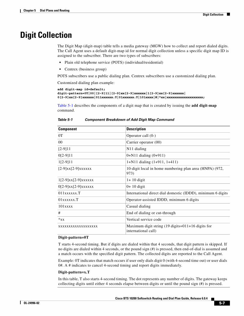
Table 5-2 shows how the USE-DIAL-PLAN token in the Carrier table impacts routing.
Table 5-2 Impact of the USE-DIAL-PLAN Token on Routing
Type of Call USE-DIAL-PLAN=Y USE-DIAL-PLAN=N
NAT
1+ Call
Route based on dial plan. Route based on Carrier table.
OPR
101XXXX+0-, 00 Operator Call
Based on EA-USE-PIC1 flag in the Subscriber Profile table. If the EA-USE-PIC1 flag is set to N, the call is routed to the LECOSS; otherwise, use PIC1.
If a Carrier supports operator services, use the route guide defined in the Carrier table; otherwise, use LECOSS-RG.
Same as USE-DIAL-PLAN=Y.
NAT-OPR
(101XXXX) 0+ call
Based on EA-USE-PIC1 flag in the Subscriber Profile table. If the EA-USE-PIC1 flag is set to N, the call is routed to the LECOSS; otherwise, use PIC1.
If a carrier supports operator services, use the route guide defined in the Carrier table; otherwise, use LECOSS-RG.
Same as USE-DIAL-PLAN=Y.
SAC
SAC call (500, 700, 900)
Route based on dial plan. Route based on Carrier table.
DA
Directory assistance (DA, DA-TOLL)
Route based on dial plan. Route based on Carrier table.
TOLL-FREE
Toll-free call (8XX)
Route based on dial plan. Route based on Carrier table.
5-11Cisco BTS 10200 Softswitch Routing and Dial Plan Guide, Release 6.0.4
OL-24996-02

Chapter 5 Dial Plans and RoutingDigit Analysis
Local Service AreaThe Local Service Area (LSA) table provides extended local service. If a NANP-dialed call results in an intraLATA toll or an interLATA call, and the subscriber has an LSA ID assigned, the LSA table is screened to check if the dialed digits appear in the subscriber’s LSA area. If the dialed digits are found in the LSA table, the call is converted to a local call.
INTL
(101XXXX) 011+ International call
Route based on international dial plan. Route based on Carrier table.
INTL-OPR
(101XXXX) 01+ international operator call
Based on EA-USE-PIC1 flag in the Subscriber Profile table. If the EA-USE-PIC1 flag is set to N, the call is routed to the LECOSS; otherwise, use PIC1.
If a Carrier supports operator services, use the route guide defined in the Carrier table; otherwise, use LECOSS-RG.
Same as USE-DIAL-PLAN=Y.
CUT-THRU
101XXXX+#
Use Carrier information; use the route guide defined in the Carrier table.
Same as USE-DIAL-PLAN=Y.
COIN/Hotel-Motel
Coin line (OLI=23, 27, 70)
Hotel motel line (OLI=6)
Treated as an operator call. If a Carrier supports operator services, use the route guide defined in the Carrier table; otherwis,e use LECOSS-RG.
Same as USE-DIAL-PLAN=Y.
Table 5-2 Impact of the USE-DIAL-PLAN Token on Routing (continued)
Type of Call USE-DIAL-PLAN=Y USE-DIAL-PLAN=N
5-12Cisco BTS 10200 Softswitch Routing and Dial Plan Guide, Release 6.0.4
OL-24996-02

Chapter 5 Dial Plans and RoutingClass of Service Screening
Class of Service ScreeningClass of service (CoS) screening allows subscribers, or a group of subscribers, to have different collections of privileges and features assigned to them.
The CoS Restrict (cos-restrict) table identifies the restrictions on a subscriber’s class of service, including restrictions on the calls the subscriber can make (screening).
Call type and casual call screening are not performed for NANP and international operator calls, even though NANP or casual call restrictions are requested for a calling party.
Account codes are not collected for:
• 0+, NANP operator calls
• 01+, international operators calls
• Local calls
Class of call screening examples are:
• Block based on call types (900, 411, operator)
• NANP restrictions based on call type (local, intraLATA, national, or all NANP)
• International restrictions (all CC, none, B/W list)
• Casual call restrictions (no restrictions, no casual calls, B/W list)
• Originating line information (OLI) restrictions for tandem calls
• Account codes
• Authorization codes
5-13Cisco BTS 10200 Softswitch Routing and Dial Plan Guide, Release 6.0.4
OL-24996-02

Chapter 5 Dial Plans and RoutingRouting
RoutingThis section provides information relating to the routing of calls by the Cisco BTS 10200. The following topics are discussed:
• Office Code
• Ported Office Code
• Route Guide
• Route
• Trunk Group
Office CodeThe Office Code (office-code) table specifies the office codes assigned to a particular Call Agent. The office codes defined in this table normally terminate to a subscriber. This table defines the office-code-index (normalized office code) that is used as an index in the DN2Subscriber table.
Ported Office CodeThe Ported Office Code (ported-office-code) table specifies numbers, or ranges of numbers, that might have been ported-in to this switch. If a called number matches any of the ported numbers, or is within any of the specified ranges of numbers, the Call Agent queries the DN2subscriber table to determine the current status of the DN.
Route GuideThe Route Guide (route-guide) table holds routing information based on policy-type.
RouteThe Route (route) table contains a list of up to ten trunk groups for call routing. If all the trunk groups are busy or not available, call processing uses the alt-route-id (if specified) to route the call. The EMS provisions the Call Agent ID field based on the Trunk Group table.
Note The Route table allows the service provider to provision a list of up to 10 trunk groups (TG1 to TG10), and a parameter for selecting the priority of the TGs for routing (TG-SELECTION). The system attempts to route the call on the highest priority TG. If the call cannot be completed on the highest priority TG, the system attempts to use the next (lower priority) TG, a process known as route advance. The system attempts route advance to lower priority TGs up to three times. (Any TG in the list that is administratively out of service is not counted as an attempt.) If all three attempts fail, the call is released, and the system provides a release announcement.
5-14Cisco BTS 10200 Softswitch Routing and Dial Plan Guide, Release 6.0.4
OL-24996-02

Chapter 5 Dial Plans and RoutingTrunk Group Types
The Route table enables:
• 10 trunk groups per route
• Digit manipulation per trunk group
• Linking of multiple routes
Trunk GroupThe Trunk Group (trunk-grp) table identifies the trunk group and maps it to the associated media gateway.
Trunk Group TypesThe Cisco BTS 10200 supports the following trunk group types: announcement, channel associated signaling (CAS), Integrated Services Digital Network (ISDN), Signaling System 7 (SS7), and SOFTSW (Session Initiation Protocol (SIP)). The Trunk Group table defines common information based on the trunk group type. The Cisco BTS 10200 supports announcement, CAS, ISDN, SS7 and SOFTSW trunk group profiles. The following trunk group types are discussed:
• Announcement
• Channel Associated Signaling
• Integrated Services Digital Network
• Signaling System 7
• Session Initiation Protocol
AnnouncementThe Announcement Trunk (annc-trunk) table is used when an announcement server is required in an Asynchronous Transfer Mode (ATM) network.
Channel Associated SignalingThe CAS Trunk Group Profile (cas-tg-profile) table holds common information on a CAS trunk group. It supports the following signaling types: dual tone multifrequency (DTMF) loop start, DTMF ground start, multifrequency (MF) im start, MF wink start, DTMF im start, DTMF wink start. A cas-tg-profile record can be shared by multiple CAS trunk groups.
5-15Cisco BTS 10200 Softswitch Routing and Dial Plan Guide, Release 6.0.4
OL-24996-02
Chapter 5 Dial Plans and RoutingGeneric Address Parameter Based Routing
Integrated Services Digital NetworkThe ISDN Trunk Group Profile (isdn-tg-profile) table holds common information regarding an ISDN trunk group. This table is used to configure the Cisco BTS 10200 to interact with various types of private branch exchanges (PBXs) having different configurations (such as non-facility associated signaling (NFAS), facility associated signaling (FAS), and so forth), initialization procedures (service or restart), and to support different call control or maintenance timer values. The isdn-tg-profile record can be shared by multiple ISDN trunk groups. The table tokens configure the Call Agent to communicate with a particular PBX.
Signaling System 7The SS7 American National Standards Institute (ANSI) Trunk Group Profile (ss7-ansi-tg-profile) table holds common information regarding an SS7 trunk group such as continuity test (COT). This table can be shared by multiple SS7 trunk groups.
Session Initiation ProtocolThe Softswitch (SIP) Trunk Group Profile (softsw-tg-profile) table holds all the information specific to a Softswitch trunk, such as ID, protocol, indicators, and echo suppression. The softsw-tg-profile record can be shared by multiple softswitch trunk groups. An ID must be created in this table before entries can be added to the Softswitch Trunk Group table.
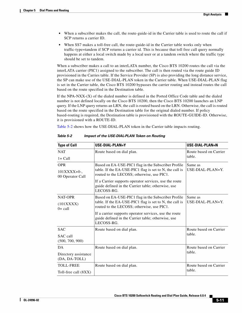
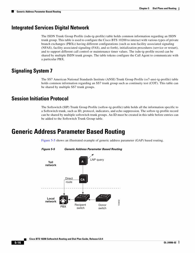
Generic Address Parameter Based RoutingFigure 5-5 shows an illustrated example of generic address parameter (GAP) based routing.
Figure 5-5 Generic Address Parameter Based Routing
1438
32
PBXRecipent
switchDonorswitch
Directroute
A
CA
Localnetwork
LNP queryToll
network
5-16Cisco BTS 10200 Softswitch Routing and Dial Plan Guide, Release 6.0.4
OL-24996-02
Chapter 5 Dial Plans and RoutingTandem Provisioning
Tandem ProvisioningThis section provides general information on tandem provisioning. For detailed information, refer to the Cisco BTS 10200 Softswitch CLI Database. The following topics are discussed:
• Automatic Number Identification
• Automatic Number Identification Screening
• Automatic Number Identification Screening Profile
• Cause Code Map
• Cause Code Map Profile
• H.323 Gateway
• H.323 Gateway to Gatekeeper
• H.323 Terminal
• H.323 Terminal Profile
• H.323 Trunk Group Profile
• II White Black List
• Service Provider
• Technical Prefix Group
• Technical Prefix Group Profile
• Trunk Group Feature Data
• Trunk Group Service Profile
Automatic Number IdentificationThe ANI table is used for the ANI screening feature. The table keeps track of allowed/blocked status ANI. If the ANI status is blocked, the call is not allowed.
Automatic Number Identification ScreeningThe ANI Screening (ani-screening) table performs ANI screening on calls received over a trunk group. Normally, ANI screening is performed on calls received from a PBX (ISDN, H.323, and Session Initiation Protocol (SIP)). This table allows the performance of ANI-based routing in addition to ANI screening. When a record is found that matches the incoming ANI, the subscriber ID associated with the record is used for further digit analysis and routing.
Automatic Number Identification Screening ProfileThe ANI Screening Profile (ani-screening-profile) table defines an ID to perform ANI screening. The ID is assigned to a trunk group when ANI screening is required or when ANI-based routing is required for calls originating over a trunk group.
5-17Cisco BTS 10200 Softswitch Routing and Dial Plan Guide, Release 6.0.4
OL-24996-02

Chapter 5 Dial Plans and RoutingTandem Provisioning
Cause Code MapThe Cause Code Map (cause-code-map) table processes cause codes received from an outgoing interface. The cause-code-map table also processes cause codes when sending cause codes to a previous switch. It also specifies why a call was released.
When used for an outgoing interface, this table serves the following purposes:
• Determines what action the Cisco BTS 10200 takes for cause codes received over an outgoing interface
• Maps received cause codes to normalized cause codes
When used for an incoming interface, the table maps normalized cause codes to a cause code sent over the incoming interface. If no entry is found in the table, the Cisco BTS 10200 uses the cause code as is.
Cause Code Map ProfileThe Cause Code Map Profile (cause-code-map-profile) table defines cause code map IDs, defines default mappings to a standard cause code (Q.850), and defines default actions to take. The cause code map IDs must be provisioned before the Cause Code table or the Trunk Group table are provisioned.
H.323 GatewayThe H.323 Gateway (h323-gw) table defines the capabilities of each H.323 protocol gateway. There can be four instances of an H.323 gateway running on the Call Agent at any one time.
H.323 Gateway to GatekeeperThe H.323 Gateway to Gatekeeper (h323-gw2gk) table describes gatekeeper characteristics for each gateway in an H.323 network. Multiple gateways can have the same gatekeeper, or there can be a different gatekeeper for each gateway. However, a gateway can be registered to only one gatekeeper at a time. A gatekeeper identifies, controls, counts, and supervises gateway traffic, including, but not limited to, gateway registration, address resolution, bandwidth control, and admission control.
H.323 TerminalThe H.323 Terminal (h323-term) table holds information about H.323 terminals (such as H.323 audio/video phones) managed by the Call Agent and known in advance. This table is specific to H.323 subscribers.
H.323 Terminal ProfileThe H.323 Terminal Profile (h323-term-profile) table defines the characteristics of group of H.323 terminals (or phones). An h323-term-profile ID must be created in this table before any H.323 subscriber entries can be added. This table contains almost all the same fields as from the H.323 Trunk Group Profile table, except for some that are specific to trunk side (such as Generic Transparency Descriptor (GTD)).
5-18Cisco BTS 10200 Softswitch Routing and Dial Plan Guide, Release 6.0.4
OL-24996-02

Chapter 5 Dial Plans and RoutingTandem Provisioning
H.323 Trunk Group ProfileThe H.323 Trunk Group Profile (h323-tg-profile) table defines the characteristics of each H.323 trunk. An h323-tg-profile ID must be created in this table before H.323 trunk group entries can be added.
II White Black ListThe II White Black List (ii-wb-list) table allows or blocks calls from certain types of lines. The CoS Restrict ID specifies whether the list is to be used as a White List or Black List.
Service ProviderThe Service Provider (service-provider) table is used when there are multiple service providers providing service through a single logical Call Agent.
Technical Prefix GroupThe Technical Prefix Group (tech-prefix-grp) table provides a list of technical prefixes supported by a gateway. The same tech-prefix-list ID can be shared by multiple gateways. Each gateway must register the tech-prefixes that it supports to its gatekeeper..
Technical prefixes allow the inclusion of special characters in a called number. These special characters are commonly designated as a 1#, 2#, 3#, and so forth, and can be configured to prepend called number on the outgoing VoIP dial peer. The gatekeeper then checks its gateway technical prefix table for gateways registered with that particular tech prefix. Technology prefixes can also be used to identify a type, class, or pool of gateways.
The gatekeeper can be provisioned with technical prefixes in one of the following ways:
• Dynamically registered technical prefixes. The H.323 gateway registers one or more technical prefixes with the gatekeeper.
• Statically registered technical prefixes. The gatekeeper is provisioned with the technical prefixes and the gateways supporting them.
• Default technical prefixes also registered statically at the gatekeeper. If the gatekeeper does not receive a technical prefix in the admission request (ARQ), the gatekeeper uses the default technical prefixes.
One or more of technical prefixes can be provisioned in Cisco BTS 10200 and this group can be associated to an H.323 gateway. The Cisco BTS 10200 H.323 gateway process instance registers the technical prefixes from its technical prefix group with its primary gatekeeper. The technical prefix is encoded in the terminal Alias field of a registration request (RRQ) message as E.164 addresses. The gatekeeper routes calls to the Cisco BTS 10200 H.323 gateway based on the technical prefixes.
Technical Prefix Group ProfileThe Technical Prefix Group Profile (tech-prefix-grp-profile) table identifies the IDs used for the Technical Prefix Group table. These IDs must be created in this table before entries can be added to the Technical Prefix Group table.
5-19Cisco BTS 10200 Softswitch Routing and Dial Plan Guide, Release 6.0.4
OL-24996-02

Chapter 5 Dial Plans and RoutingLocal Toll-Free Service Provisioning
Trunk Group Feature DataThe Trunk Group Feature Data (trunk-grp-feature-data) table performs CoS screening for Tandem calls. If the received ANI is not found in the ANI table, and the casual-call flag is set to Y, the call is allowed. If the casual-call flag is set to N, the call is blocked. The cos-restrict-id performs the CoS screening.
Trunk Group Service ProfileThe Trunk Group Service Profile (trunk-grp-service-profile) table links a trunk group to services.
Local Toll-Free Service ProvisioningThe purpose of toll-free services is to have the called party, rather than the calling party, charged for the call. These calls are prefixed with the 1+8XX service access codes. The seven digits following the 8XX codes are used for routing the call. For an inbound/outbound 8XX call, the Cisco BTS 10200 checks the local toll-free database first. If the corresponding DN is not found in the local toll-free database, the system sends a query to the service control point (SCP) to request the corresponding DN.
All aspects of toll-free calling are transparent to the caller. A caller expects to dial 1-8XX-NXX-XXXX to reach the desired destination. The company that translates the number to a specific DN, and the company that routes the call, must appear transparent to callers. Most callers are not aware that their dialed 8XX number is changed into a specific DN. What matters to the callers is that they reach what they perceive to be the called number, and they are not billed for the call.
The following additional topics are discussed in this section:
• Local Toll-Free Database
• Service Control Point-Based Toll-Free Services
• Automatic Number Identification White/Black List
• Customer Group
• DN2 Customer Group
• II Restrict List
5-20Cisco BTS 10200 Softswitch Routing and Dial Plan Guide, Release 6.0.4
OL-24996-02

Chapter 5 Dial Plans and RoutingLocal Toll-Free Service Provisioning
Local Toll-Free DatabaseThe Cisco BTS 10200 provides the ability to translate inbound/outbound 8XX numbers at the Feature Server (FS) using a local 8XX database. The 8XX service supports the following features:
• Origin-dependent routing
• Time-of-day routing
• Percentage-based routing
• Information digit-based screening
• Black/white list screening
The Cisco BTS 10200 also supports optional dialed number identification service (DNIS). In an 8XX DNIS, when a call is terminated to a PBX (call center), 4 digits are outpulsed to the PBX to identify the originally dialed 8XX number. In case of custom DNIS, up to 22 digits can be outpulsed with additional information such as:
• Original 8XX number dialed
• Automatic number identification (ANI)
• Originating line information of the calling party
When a translated number (for an original 8XX call) is received, the Analyzed Info Dial Plan (DP) triggers the FS. The Cisco BTS 10200 looks up the DNIS and TG information for the call. The DNIS information is then outpulsed to the PBX. If an overflow condition is encountered, the call is routed to the overflow trunk. The overflow trunk can be a public switched telephone network (PSTN) trunk.
Service Control Point-Based Toll-Free ServicesThe Cisco BTS 10200 communicates with an SCP-based database called the toll-free database service, which contains information for routing the call. The database service provides information about the network service provider selected to complete the call, as well as information for translating the toll-free number to a specific 10-digit DN. The routing of the call can vary depending on the arrangements made between the toll-free subscriber and the network service provider. These arrangements can include selective routing based on the time of day, day of week, and location from which the call originates.
Automatic Number Identification White/Black ListThe ANI White/Black List (ani-wb-list) table performs ANI screening on 800 calls. The Customer Group specifies if the list is to be used as a White List or a Black List. A White/Black List specifies whether calls are allowed to connect (white) or not allowed to connect (black).
Customer GroupThe Customer Group (cust-grp) table defines the cust-grp-id and how ANI call forwarding and call restrictions are applied.
5-21Cisco BTS 10200 Softswitch Routing and Dial Plan Guide, Release 6.0.4
OL-24996-02

Chapter 5 Dial Plans and RoutingLocal Toll-Free Service Provisioning
DN2 Customer GroupThe DN2 Customer Group (dn2cust-grp) table provides translation of inbound/outbound 8XX (toll free) numbers to a local number and designated carrier.
II Restrict ListThe II Restrict List (II-restrict-list) table restricts certain types of originating line services for a given group. The use of the list is determined by provisioning in the Customer Group table. This is a Black List (restrict) only. It cannot be a White List.
5-22Cisco BTS 10200 Softswitch Routing and Dial Plan Guide, Release 6.0.4
OL-24996-02

Chapter 5 Dial Plans and RoutingCarriers and Service Providers
Carriers and Service ProvidersThis section provides general carrier/service provider information. The following subjects are discussed:
• Carrier
• Route Guide
• Circuit Code
• Service Provider
CarrierThe Carrier (carrier) table defines the characteristics and capabilities supported by interLATA carriers, intraLATA carriers, and international carriers, and it also provides routing information.
The following conditions apply when route-guide-id in the Carrier table is configured for a toll-free call:
• When a subscriber makes the call, the route-guide-id in the Carrier table is used to route the call if SCP returns a carrier ID.
• When SS7 makes a toll-free call, the route-guide-id in the Carrier table works only when traffic-type=tandem if SCP returns a carrier id. This is because that toll free call query normally happens at either a local switch made by a local user or at a tandem switch where the traffic type should be set to tandem.
Route GuideThe Route Guide (route-guide) table holds routing information based on policy-type. The Policy Prefix (policy-prefix) table provides information for call routing based on prefix (type of call). Typical call types include 1+ dialing, international calls, toll-free, and so on. This table is used mainly for carrier routing. The Policy Point of Presence (policy-pop) (POP) based policy routing routes a call to the nearest trunk group when there are multiple trunk groups.
There are several situations where a policy POP can be used. If a Call Agent serves several POPs, each POP can have its own announcement server. A POP-specific announcement server can be more efficient than a centralized announcement server. InterLATA carriers also have a point of presence in each POP. Route interLATA or international calls to the nearest carrier location using policy POP routing.
The Policy Origin Dependent Routing (policy-odr) table is used for origin-dependent routing. The numbering plan area (NPA) (or NPA-NXX) of the calling party number selects a route. If no match is found based on the calling party number, the route marked as default routes the call.
The Policy Region (policy-region) table performs region-based routing. The region is derived using the Region Profile table from the Route Guide table and the calling party number ANI. If ANI is not available or the Region Profile table is not provisioned, the region assigned to the trunk group is used for trunk origination. If a record cannot be found based on the region, the record with region=default (if provisioned) is used for routing.
For additional information on call types, refer to Appendix A, “Call Types and Subtypes.”
5-23Cisco BTS 10200 Softswitch Routing and Dial Plan Guide, Release 6.0.4
OL-24996-02

Chapter 5 Dial Plans and RoutingCarrier Based Routing
Circuit CodeThe Circuit Code (circuit-code) table defines the circuit code value for the transit network selection (TNS) parameter. The circuit code value is defined based on the line, class of service, and call type. Special circuit code values are assigned to calls from coin or hotel or motel lines. If special circuit code values are not required, the default circuit code values are based on the call type sent.
Service ProviderThe Service Provider (service-provider) table is used when there are multiple service providers providing service through a single logical Call Agent.
Carrier Based RoutingCarrier based routing enables the routing of Cisco BTS 10200 calls based on carrier. Carrier based routing provides multiple service provider support. Additionally, carrier based routing enables matching of the carrier ID and the trunk group to individual service providers. Individual dial plans can be configured for each service provider, or default routing can be enabled.
Call Processing FlowThis section describes the Cisco BTS 10200 call processing flow for calls terminating on a trunk and for calls terminating at a subscriber. The following topics are discussed:
• Trunk Termination
• Subscriber Termination
Trunk TerminationThe trunk termination call flow is:
• Termination
• Subscriber
• Dial-plan
• Destination
• Route-guide
• Route
• Trunk group
• Trunk
• Termination
5-24Cisco BTS 10200 Softswitch Routing and Dial Plan Guide, Release 6.0.4
OL-24996-02

Chapter 5 Dial Plans and RoutingCall Processing Flow
Subscriber TerminationThe subscriber termination call flow is:
• Termination
• Subscriber
• Dial-plan
• Destination
• Office-code
• DN2Subscriber
• Subscriber
• Termination
5-25Cisco BTS 10200 Softswitch Routing and Dial Plan Guide, Release 6.0.4
OL-24996-02

Chapter 5 Dial Plans and RoutingCall Processing Flow
5-26Cisco BTS 10200 Softswitch Routing and Dial Plan Guide, Release 6.0.4
OL-24996-02