diagnosis of aar and def: comparison of residual …
TRANSCRIPT

DIAGNOSIS OF AAR AND DEF: COMPARISON OF RESIDUAL EXPANSION, STIFFNESS DAMAGE TEST AND DAMAGE RATING
INDEX
Renaud-Pierre Martin1*, Leandro Sanchez2, Benoît Fournier3, François Toutlemonde1,
1 Université Paris-Est, IFSTTAR, Materials and Structures Department, Marne-la-Vallée Cedex 2, FRANCE
2 University of Ottawa, ON, CANADA
3 Laval University, Geology and Geological Engineering Department, Quebec, QC, CANADA
Abstract Aging concrete structures affected by internal swelling reactions (ISR) may be quite difficult to manage. Over the last few years, several tools were developed in order to provide diagnostic assessment of aging concrete structures, especially those affected by alkali-aggregate reaction (AAR). Among those tools, the Stiffness Damage Test (SDT), Damage Rating Index (DRI) and Residual Expansion (RE) seem to have a great potential. However, the comprehensive character of the tools in assessing different mechanisms other than AAR was barely verified, which reduces their use in engineering purposes. This paper presents the results of a study where the above three tools were used for assessing the condition of a concrete structural element damaged by ASR+DEF coupling. Results show that the three procedures were similarly capable of providing a diagnosis quantitative estimate of the expansion attained by the concrete. Finally, although theoretically different, the test procedures seem to have a somehow complementary character, and could potentially be used together in engineering practices. Keywords: Diagnosis, AAR, DEF, Stiffness Damage Test, Damage Rating Index, Residual expansion test 1 INTRODUCTION: ISR DAMAGE IN CONCRETE
Alkali Aggregate Reaction (AAR) and Delayed Ettringite Formation (DEF) are both endogenous processes that lead to concrete expansion and distress, being part of the so-called internal swelling reaction (ISR) mechanisms. Although quite different, both mechanisms cause cracking and decrease the mechanical properties of affected concrete [1]. Normally, AAR begins within the reactive aggregate particles, spreading into the cement paste at high expansion levels [2,3], while DEF is often considered to result in a uniform expansion of the cement paste, which causes distress especially in the boundaries between the aggregate particles and the cement paste (i.e. interfacial transition zone - ITZ) [4].
Usually, AAR and DEF are studied separately. However, in the field, they are often found simultaneously, which leads to quite complex mechanisms as described by [1], and leads to difficult identification of the damage process and possible controversial diagnostics [5-6]. The reason of this synergy is not completely understood, although it has been found that the cracking-induced process caused by one mechanism might contribute at weakening the material and facilitating the occurrence of the other; moreover, the consumption of alkalis by AAR triggers the precipitation of ettringite and thus DEF expansion [1].
2 TOOLS FOR ASSESSING CONCRETE DAMAGE CAUSED BY ISR
One of the biggest challenges in civil engineering is to establish the correlation between damage "signatures" which appear on distressed concrete elements affected by different damage mechanisms and: 1) the expansion level attained by those concrete elements; 2) the losses in either the stiffness or the mechanical properties/durability of the elements distressed (both related to the physical integrity of the distressed material) and also; 3) the potential for further distress of those concrete elements [3;7-9].
* Correspondence to: [email protected]

In this context, it has been found that AAR and DEF strongly influence the mechanical properties of affected concrete, which could raise severe concerns in terms of serviceability, structural integrity and durability of the affected structures/structural members [10]. Therefore, the development and use of laboratory/field procedures or tools which might evaluate the actual distress degree (diagnosis and assessment), its development over the years and even predict its further damage (prognosis) would be extremely desirable, mainly for the selection of effective methods for rehabilitating affected structures. Over the years, several tools were developed and used for the condition assessment of concrete elements or structures affected by ISR, especially AAR, and among them, three procedures showed to be the most promising: a) the Stiffness Damage Test (SDT), b) the Damage Rating Index (DRI) and; c) the Residual Expansion (RE). Although some of them have been used for years in affected structures management protocols [10], they have not been subject of intercomparison and comparative qualification.
2.1 Stiffness Damage Test (SDT) In the early 1990’s, Crisp and co-workers proposed the use of the Stiffness Damage Test (SDT) to quantify the degree of distress in concrete affected by ASR [11-12]. The test method was developed by Walsh [13] who observed its suitability for evaluating rock specimens. Crouch [14], following Walsh works, proposed the new SDT procedure in concrete, based on cyclic compression loading of specimens. Sanchez et al. [3,8,9] pursuing the work of Smaoui and co-workers [15], used the SDT for the condition assessment of concrete specimens cast in the laboratory, with a variety of mix-designs and reactive aggregates (coarse vs. fine). Based on the above extensive investigation program and statistical analysis of the test results, the authors presented the following main conclusions: 1) the SDT should be carried out with a percentage of the concrete strength instead of using a fixed load; 2) the use of 40% of the design concrete strength seems to be the best approach for distinguishing damaged concrete specimens with regard to their expansion levels; 3) the use of percentages up to 40% seems to keep the test “non-destructive”, at least for the expansion levels studied (up to 0.30%); 4) the output parameters such as the hysteresis area (HA) and the plastic deformation (PD) over the five cycles, as well as the modulus of elasticity (ME) (as an average value of the second and third cycles), were found as diagnostic parameters; 5) the input parameters such as the concrete’s cure history (i.e. the specimen moisture condition), the sample’s geometry and size, the sample’s location within the structural member (zone and direction), as well as the selection of the sample’s strength level for stiffness damage testing, may influence the output analyses of the SDT; 6) the use of indices (Stiffness Damage Index - SDI and Plastic Deformation Index - PDI) instead of absolute HA or PD values, decreased the impact of a poor selection of maximum loading level for stiffness damage testing and thus provides easier understanding of AAR evolution as a function of its expansion [3] and; 7) although promising, to be considered a complete powerful tool, the SDT needs to show its reliability and suitability for assessing different distress mechanisms than AAR, such as DEF and freezing and thawing cycles (FT). 2.2 Damage Rating Index (DRI)
The DRI is a semi-quantitative microscopic analysis performed with the use of a stereomicroscope (about 15-16x magnification) where damage features associated with AAR are counted through a 1 cm2 grid drawn on the surface of a polished concrete section [16]. The number of counts corresponding to each type of petrographic features is then multiplied by weighing factors, whose purpose is to balance their relative importance towards the mechanism of distress considered (for instance ASR) [17-19].
Sanchez [2-3] used the new version of the DRI test procedure proposed by [16] to quantify the development of petrographic features of damage, as a function of expansion (0.05 to 0.30%) in ASR-affected 25 to 45 MPa concretes incorporating highly-reactive fine and coarse aggregates. The main conclusions found were the following: a) DRI numbers were found to increase almost linearly with increasing expansion in the test specimens for both AAR coming from reactive fine or coarse aggregates; b) the nature and progress of the microscopic features of deterioration due to ASR does not seem to change significantly according to the material strength; it seemed to change, however, according to the reactive aggregate nature (i.e. lithotypes); c) even though different DRI numbers were found according to the reactive aggregate lithotypes studied, an envelope of results came out of the study, which seemed to indicate that the microscopic method was able to identify ASR progress towards the specimens expansion levels; exception was yet found for alkali-carbonate (ACR) aggregate, which showed completely different damage patterns as a function of the expansion

development, d) a quantitative damage chart was proposed based on the analysis of the envelope of AAR results found and; e) in order to become a comprehensive test procedure, the DRI should be able to assess other mechanisms than AAR such as DEF and FT.
2.3 Residual Expansion (RE)
Residual expansion derives from a generic concept that aims at assessing the remaining expansion that could occur in the ISR affected structures from the present (already developed expansion state) until asymptotic value corresponding to infinite time. Various methods exist both for AAR (e.g. [20-22]) and DEF [23]: most of the time, RE tests are carried out on cores extracted from ISR-affected structures and then consist in monitoring the expansion of the specimens in a moist environment in the laboratory; output results are used for the prognosis of the affected structures and are sometimes used as input data in numerical tools (combined with structural monitoring for calibration purposes) to predict their mechanical behaviour [24-25]. Namely in the limit case where the RE test is performed before ISR initiation, the measured strains can be used as a direct identification of imposed prescribed strains in a chemo-mechanical approach [26].
These approaches are quite simple and output results are sometimes criticized, claiming that RE tests induce deviation in the assessment of the residual expansion due to stress release after coring or alkali leaching as an example. Therefore, some authors propose alternative tools aiming at better understanding the expansive mechanisms [27]; however, this kind of approach requires more operations. Whatsoever, “classical” RE procedures have shown promising results also in operational forensic investigations, while deserving further research [7,28].
3 SCOPE OF THE WORK
In the previous sections, the lack of information (and data) regarding the comprehensive use of mechanical and microscopic tools for appraising damage in concrete was reviewed and discussed. Therefore, the objective of the present paper is to test the reliability and efficiency of the SDT, DRI and RE in assessing damage due to other mechanisms than AAR.
In this study, a non-reinforced concrete beam was cast in the laboratory and subjected to conditions enabling the development of AAR and DEF simultaneously. Then, the structural element was monitored over time and, after six months of ageing, the beam was cored at different locations for mechanical and microscopic evaluations. The reliability of the above tools for condition assessment was studied and a discussion on their potential use is presented.
4 MATERIALS AND METHODS 4.1 Investigated structure description
A beam, 0.25 x 0.50 x 3.00 m3, was cast in the Ifsttar laboratory with a concrete incorporating an alkali-silica reactive limestone and exposed to 3 days curing at 80°C right after casting to simulate the curing conditions of a massive structure. Detailed composition of the concrete mix and of the heat treatment procedure are provided in [7,29,30].
After the initial heat treatment, the beam was stored and monitored in the laboratory at a constant temperature of 38°C. Specific water supply conditions were applied and are illustrated in Figure 1: the bottom of the beam was immersed in water while the upper part was maintained at 30% Relative Humidity (RH); the lateral surfaces were sealed with adhesive aluminium foils. The beam was placed on two simple bearings during the whole procedure (span of 2.8 m).
This procedure led to the development of important expansion levels due to coupled ASR and DEF in the structure. Moreover, due to the vertical moisture gradient, a very high expansion level was developed in the lower part of the beam while little expansion or even shrinkage was observed in the upper part. This resulted in failure of the beam after less than 6 months of ageing, as described in [29]. After failure, the beam was stored at ambient temperature without any external water supply prior to coring. 4.2 Coring
34 months after failure, 20 cores were extracted at different depths within the structural element, varying according to the beam height (top to bottom): 0.08, 0.17, 0.27, 0.37 and 0.44 m (4 cores – 110 mm in diameter – per depth). Two cores were used to perform the SDT, one for the DRI and one for RE. (Note: RE tests were already performed right after failure of the beam, results are presented in [29]. The new RE tests performed for this study were carried out to check if the material had developed further expansion/damage during the 34 months of storage.). Figure 2 gives the

position of the cores within the beam. An effort was made to avoid zones with major cracks while coring.
4.3 Methods for assessment and analysis Stiffness damage test (SDT)
Two samples per depth of the structure were subjected to five cycles of loading/unloading at a controlled loading rate of 0.10 MPa/s. The SDT was performed in a slightly different way as compared to the studies carried out by [8,9] (i.e. loading of 30% of the 28-day concrete strength instead of 40%). This choice was made taking into consideration a quite unusual situation where AAR and DEF coupling had largely decreased the compressive strength of the affected concrete (~ up to - 80% compared to the compressive strength at 28 days [7]), especially the ones located in the lower portion of the beam. Thus, the use of 40% of the 28-day strength would have been greater than the residual compressive strength of the cores and it would likely have caused the specimens failure. Moreover, according to [3,8,9], from 30% of the strength of the material, SDT starts becoming diagnostic. Thereby, the choice of 30% was made. All the results presented hereafter are the average values of those two specimens at each structure depth.
Damage Rating Index (DRI)
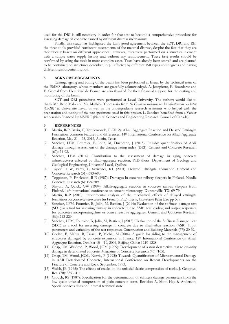
The DRI was performed on one specimen per beam depth, according to the procedure proposed by [16] and considering all the damage features (e.g. cracking) in aggregate particles down to 1 mm in size (instead of 2 mm). The latest weighing factors proposed by [16] were also used for the calculation of the DRI numbers. Examples of the petrographic features of deterioration used for the DRI are given in Figure 4.
Residual expansion (RE) and assessment of expansion of the beams
The RE measurements were performed according to a procedure derived from [20] and [23]: after drilling, stainless steel pins were installed along the vertical axis of the cores every 120° to ensure monitoring of the longitudinal expansion of the specimens with a digital extensometer. Then, the cores were stored at 38°C in water during almost 600 days. Special care was taken while performing this test and this is fully discussed in [28]: in particular, for the investigations presented in this paper, RE tests were performed right after coring to assess as close as possible the “real” residual expansion of the concrete; Moreover, the full RE curves were considered in the analysis (i.e. no swelling phase due to water uptake was considered). 5 RESULTS 5.1 SDT
SDI results are given in Table 1. Specimens extracted at 37 and 44 cm depths were so damaged that they couldn’t withstand the 5 SDT cycles: at both depths, one of the specimens failed during the first loading cycle; the second failed before the end of the 5 cycles. Therefore, all SDI were calculated only for the first cycle to allow comparing the different locations within the beam. This procedure was found to be valid as discussed by [3,8,9].
Figure 3 describes the stress-strain behaviour of the specimens during the test. In agreement with the water supply conditions, the deeper the core, the higher the damage. SDI values ranged from 0.37 at 0.08m depth to 0.85 at 0.44m depth, which can be considered high to very high [3]; actually, a SDI value of 0.8 indicates that 80% of the loading energy applied is dissipated over the loading-unloading cycles.
5.2 DRI
DRI results are given in Table 1. Figure 4 illustrates typical microscopic features identified in the polished concrete sections. Figure 5 gives the distribution of the different petrographic damage features (with their respective weighing factors), resulting in the global DRI number. Similarly to the SDT results, the deeper the core in the beam, the higher the DRI. DRI numbers ranged from ~ 900 at 0.08m depth to over 2000 at 0.44m depth. Moreover, one could notice that the greater the depth, the greater the damage in the cement paste (CCP - orange bars).
It is important to mention that when visible, the reaction products (either ettringite or ASR gel) were taken into account while performing the DRI observations. However, no distinction was made between ettringite and ASR gel, as the products are difficult to distinguish at the magnification used for the DRI (≈16x). However, this procedure did not change the final results since the weighing

factors used for cracks without and with reaction products of any types are exactly the same, as suggested by [16].
5.3 Residual expansion
Residual expansion test results are given in Figure 6. These tests confirm the effect of the applied moisture gradient: the deeper the core, the lower the residual expansion. This implies that a larger expansion occurred in the lower part of the beam prior to performing the residual expansion test, as expected.
It has been established that, for unrestrained specimens, it is possible to assess the expansion that occurred prior to coring knowing the full expansion potential of the material [7,31]: expansion before coring is assessed by subtracting the residual expansion from the total free expansion of the material. For the concrete studied in this investigation, free expansion has been measured and is equal to 1.55 % (see [1,29]). The corresponding estimates of expansion attained before coring are given in Table 1. Figure 7 describes the superposition of the free expansion curve of the concrete of the beam (i.e. monitoring of concrete expansion right after casting described in [1]) and of the RE curves; in other words, values of expansion presented in Table 1 were applied as offsets on the RE results presented in Figure 6.a. A fairly good correlation between the different curves exists as described in [7,28,31]: thus, in the simple case studied in this paper (non-reinforced beam), RE tests provide a fairly good and consistent assessment of the “real” expansion of the material.
6 DISCUSSION
Figure 8.a represents the evolution of SDI as a function of concrete expansion. The correlation between these parameters has been established for materials affected by AAR [3]. For the specific concrete investigated in this study and affected by coupled AAR+DEF, a fairly good correlation is established between these two parameters and emphasizes the promising comprehensive application of SDT for assessing damage from ISR mechanisms other than pure AAR. However, these are just preliminary results obtained on a few specimens studied from only one concrete structure; thus, the efficiency of SDT should be re-assessed and confirmed throughout an extensive study, using a wide range of structure types (i.e. different geometries, reinforcement, restraints and environmental conditions, etc.), reaction mechanisms and field cores extracted from aging structures.
Figure 8.b illustrates the correlation between DRI values and expansion of concrete. DRI and expansion follow the same trend: microstructural distress increases as a function of the expansion development. Moreover, a rough correlation between these variables was established with a R2 coefficient of about 0.925. Interestingly, the number of cracks in the cement paste, compared to the ones in the aggregate particles, increased readily with increasing depths, suggesting that the proportion ASR/DEF might not be the same for all the cores studied. In this work, AAR is believed to trigger DEF effects [7,32], while DEF is likely considered the main contributor to the final damage.
Another interesting discussion regarding the comprehensive character of the DRI would be the selection of efficient weighing factors. Similar discussion is found in [33], where increasing the weighing factors used for the cement paste distress features resulted in a better correlation between DRI and expansion for DEF cases. However, despite this modification, Berubé et al. [33] indicated that DRI numbers for DEF cases remained relatively low compared to AAR-affected concretes for similar expansion levels. It seems logical though that mechanisms providing distress features in the aggregate particles present better correlation with their expansion levels when greater weighing factors are attributed to this feature type. The opposite would be seen in the case of mechanisms generating damage features in the cement paste. Therefore, an in depth study of the comprehensive use of the DRI is still necessary, in order to accommodate an overall assessment of at least the most common damage mechanisms found in aging concrete.
7 CONCLUSIONS
In this paper, the Stiffness Damage Test (SDT), Damage Rating Index (DRI) and Residual Expansion (RE) were used for assessing damage in a concrete structural element (i.e. unreinforced concrete beam) affected by coupled AAR+DEF. Cores were extracted from different locations of the element and analyses were performed in the laboratory.
Results of the tests were qualitatively in agreement with the mechanical behaviour of the beam prior to coring: the higher the expansion, the higher the SDI and the DRI number and the lower the residual expansion. Quantitative results of these tests were then compared to each other. A fairly good correlation between both the SDT (especially with the SDI parameter) and DRI number against the total expansion attained was found. However, a study focusing on the effect of the weighing factors
used for the DRI is still necessary in order for that test to become a comprehensive procedure for assessing damage in concrete caused by different distress mechanisms.
Finally, this study has highlighted the fairly good agreement between the SDT, DRI and RE: the three tools provided consistent assessments of the material distress, despite the fact that they are theoretically based on different approaches. However, tests were performed on a structural element with a simple water supply history and without any reinforcement. These first results should be confirmed by using the tools in more complex cases. Tests have already been started and are planned to be continued on structures described in [7] affected by different ISR types and degrees and having different reinforcement ratios. 8 ACKNOWLEDGEMENTS
Casting, ageing and coring of the beam has been performed at Ifsttar by the technical team of the EMMS laboratory, whose members are gratefully acknowledged. A. Jeanpierre, E. Bourdarot and E. Grimal from Electricité de France are also thanked for their financial support for the casting and monitoring of the beam.
SDT and DRI procedures were performed at Laval University. The authors would like to thank Mr. René Malo and Mr. Mathieu Thomassin from “le Centre de recherche sur les infrastructures en béton (CRIB)” at Université Laval, as well as the undergraduate research assistants who helped with the preparation and testing of the test specimens used in this project. L. Sanchez benefited from a Vanier scholarship financed by NSERC (Natural Sciences and Engineering Research Council of Canada). 9 REFERENCES [1] Martin, R-P, Bazin, C, Toutlemonde, F (2012): Alkali Aggregate Reaction and Delayed Ettringite
Formation: common features and differences. 14th International Conference on Alkali Aggregate Reaction, May 21 – 25, 2012, Austin, Texas.
[2] Sanchez, LFM, Fournier, B, Jolin, M, Duchesne, J (2015): Reliable quantification of AAR damage through assessment of the damage rating index (DRI). Cement and Concrete Research (67): 74-92.
[3] Sanchez, LFM (2014). Contribution to the assessment of damage in aging concrete infrastructures affected by alkali-aggregate reaction, PhD thesis, Department of Geology and Geological Engineering, Université Laval, Québec.
[4] Taylor, HFW, Famy, C, Scrivener, KL (2001): Delayed Ettringite Formation. Cement and Concrete Research (31): 683-693.
[5] Tepponen, P, Ericksson, B-E (1987): Damages in concrete railway sleepers in Finland. Nordic Concrete Research (6): 199-209.
[6] Shayan, A, Quick, GW (1994): Alkali-aggregate reaction in concrete railway sleepers from Finland. 16th international conference on cement microscopy, Duncanville, TX: 69-79.
[7] Martin, R-P (2010): Experimental analysis of the mechanical effects of delayed ettringite formation on concrete structures (in French), PhD thesis, Université Paris Est: pp 577.
[8] Sanchez, LFM, Fournier, B, Jolin, M, Bastien, J (2014): Evaluation of the stiffness damage test (SDT) as a tool for assessing damage in concrete due to ASR: Test loading and output responses for concretes incorporating fine or coarse reactive aggregates. Cement and Concrete Research (56): 213-229.
[9] Sanchez, LFM, Fournier, B, Jolin, M, Bastien, J (2015): Evaluation of the Stiffness Damage Test (SDT) as a tool for assessing damage in concrete due to alkali-silica reaction (ASR): Input parameters and variability of the test responses. Construction and Building Materials (77): 20-32.
[10] Godart, B, Mahut, B, Fasseu, P, Michel, M (2004): A guide for aiding to the management of structures damaged by concrete expansion in France, 12th International Conference on Alkali Aggregate Reaction, October 15 – 19, 2004, Beijing, China: 1219-1228.
[11] Crisp, TM, Waldron, P, Wood, JGM (1989): Development of a non destructive test to quantity damage in deteriorated concrete. Magazine of Concrete Research (45) (165).
[12] Crisp, TM, Wood, JGM., Norris, P (1993): Towards Quantification of Microstructural Damage in AAR Deteriorated Concrete, International Conference on Recent Developments on the Fracture of Concrete and Rock. September. 1993.
[13] Walsh, JB (1965): The effects of cracks on the uniaxial elastic compression of rocks. J. Geophys. Res. (70): 339 - 411.
[14] Crouch, RS (1987): Specification for the determination of stiffness damage parameters from the low cyclic uniaxial compression of plain concrete cores. Revision A. Mott. Hay & Anderson. Special services division. Internal technical note.

[15] Smaoui, N, Bérubé, M-A, Fournier, B, Bissonnette, B, Durand, B, (2004): Evaluation of the Expansion Attained to Date by Concrete Affected by ASR - Part I: Experimental Study. Canadian Journal of Civil Engineering (31): 826-845.
[16] Villeneuve, V, Fournier, B, (2012): Determination of the damage in concrete affected by ASR – the damage rating index (DRI). 14th International Conference on Alkali Aggregate Reaction, May 21 – 25, 2012, Austin, Texas.
[17] Shrimer, FH (2006): Development of the Damage Rating Index Method as a tool in the assessment of alkali-aggregate reaction in concrete: a critical review. Proc. Marc-André Bérubé symposium on AAR in concrete, CANMET/ACI Advances in concrete technology seminar, Montréal, Canada; 391-411.
[18] Grattan-Bellew, PE, Danay, A, (1992): Comparison of laboratory and field evaluation of AAR in large dams. Proc. of the International Conference on Concrete AAR in Hydroelectric Plants and Dams, Canadian Electrical Association & Canadian National Committee of the Int. Commission on Large Dams.
[19] Transtec Group (2009): Field Site and Petrographic Evaluation - ASR Development and Deployment Program - Field Trials and Demonstration Projects.
[20] Fasseu, P (1997): Alcali-réaction du béton – Essai d’expansion résiduelle sur béton durci, Méthode d’essai des Laboratoires des Ponts et Chaussées (ME 44), Laboratoire Central des Ponts et Chaussées: pp 12.
[21] Merz, C, Leemann, A, (2013): Assessment of the residual expansion potential of concrete from structures damaged by AAR, Cement and Concrete Research (52): 182-189
[22] Berubé, M-A, Smaoui, N, Côté, T (2004): Expansion tests on cores from ASR-affected structures, 12th International Conference on Alkali Aggregate Reaction, October 15 – 19, 2004, Beijing, China: 821 – 832.
[23] Pavoine, A, Divet, L (2009): Réaction Sulfatique Interne au béton – Essai d’expansion résiduelle sur carotte de béton extraite de l’ouvrage. Méthode d’essai des Laboratoires des Ponts et Chaussées (ME 67), Laboratoire Central des Ponts et Chaussées: pp 28.
[24] Li, K, Coussy, O, Larive, C (2004), Modélisation chimico-mécanique du comportement des bétons affectés par la réaction alcali-silice – Expertise numérique des ouvrages d’art dégradés. ERLPC (OA 43), Laboratoire Central des Ponts et Chaussées: pp 202.
[25] Seignol, J-F, Omikrine-Metalssi, O, Baghdadi, N, Toutlemonde, F (2012): From AAR to DEF: numerical modeling of structures affected by expansive reactions in concrete, 14th International Conference on Alkali Aggregate Reaction, May 21 – 25, 2012, Austin, Texas.
[26] Ulm, F-J, Coussy, O, Kefei, L, Larive, C (2000): Thermo-chemo-mechanics of ASR expansion in concrete structures, Journal of Engineering Mechanics (126): 233 – 242.
[27] Sellier, A, Bourdarot, E, Multon, S, Cyr, M, Grimal, E (2009): Combination of structural monitoring and laboratory tests for assessment of alkali-aggregate reaction swelling: Application to gate structure dam, ACI Materials Journal (106): 281 – 290.
[28] Multon, S, Barin, F-X, Godart, B, Toutlemonde, F (2008): Estimation of the residual expansion of concrete affected by Alkali Silica Reaction. Journal of Materials in Civil Engineering (20): 54-62.
[29] Martin, R-P, Renaud, J-C, Multon, S, Toutlemonde, F (2012): Structural behavior of plain and reinforced concrete beams affected by combined AAR and DEF, 14th International Conference on Alkali Aggregate Reaction, May 21 – 25, 2012, Austin, Texas.
[30] Martin, R-P, Toutlemonde, F (2013): Theoretical and experimental validation of a simple method to reproduce representative DEF-prone conditions in laboratory. Materials & Structures (46): 1245-1255.
[31] Multon, S (2004): Evaluation expérimentale et théorique des effets mécaniques de l’alcali-reaction sur des structures modèles. ERLPC (OA 46), Laboratoire Central des Ponts et Chaussées: pp 423.
[32] Martin, R-P, Renaud, J-C, Toutlemonde, F (2010): Experimental investigations concerning combined delayed ettringite formation and alkali aggregate reaction, 6th International Conference on Concrete under severe conditions, June 7 – 9, 2010, Merida, Mexico.
[33] Bérubé, M-A, Fournier, B, Côté, T (2012): Using the damage rating index for assessing the expansion of concrete affected by freeze-thaw, sulphate attack, or ASR, 14th International Conference on Alkali Aggregate Reaction, May 21 – 25, 2012, Austin, Texas.

TABLE 1: Test results (Avg = average of output result of cores nr. 2 and 3; Std = Standard deviation of output result of cores nr. 2 and 3).
Assessed expansion SDI after one cycle DRI
Core # 1 (RE) 2 3 Avg Std 4
Dep
th (
m)
0.08 0.92% 0.385 0.359 0.372 0.013 910
0.17 1.06% 0.661 0.621 0.641 0.020 1631
0.27 1.25% 0.805 0.796 0.800 0.004 1934
0.37 1.29% 0.832 - 0.832 0.000 2024
0.44 1.33% - 0.859 0.859 0.000 2064
FIGURE 1: Test set-up during ageing of the beams.
FIGURE 2: Coring outline.
FIGURE 3: Stress-strain behaviour of the specimens during SDT. The specimens correspond to
different depths in the structural element, as described in Figure 2.
0
2
4
6
8
10
12
14
-0.001 0 0.001 0.002 0.003 0.004 0.005 0.006 0.007 0.008 0.009
Stre
ss (
MP
a)
dL/L (-)
0.08_2
0.08_3
0.17_2
0.17_3
0.27_2
0.27_3
0.37_2
0.37_3
0.44_2
0.44_3
0.08 0.17 0.270.37
0.44
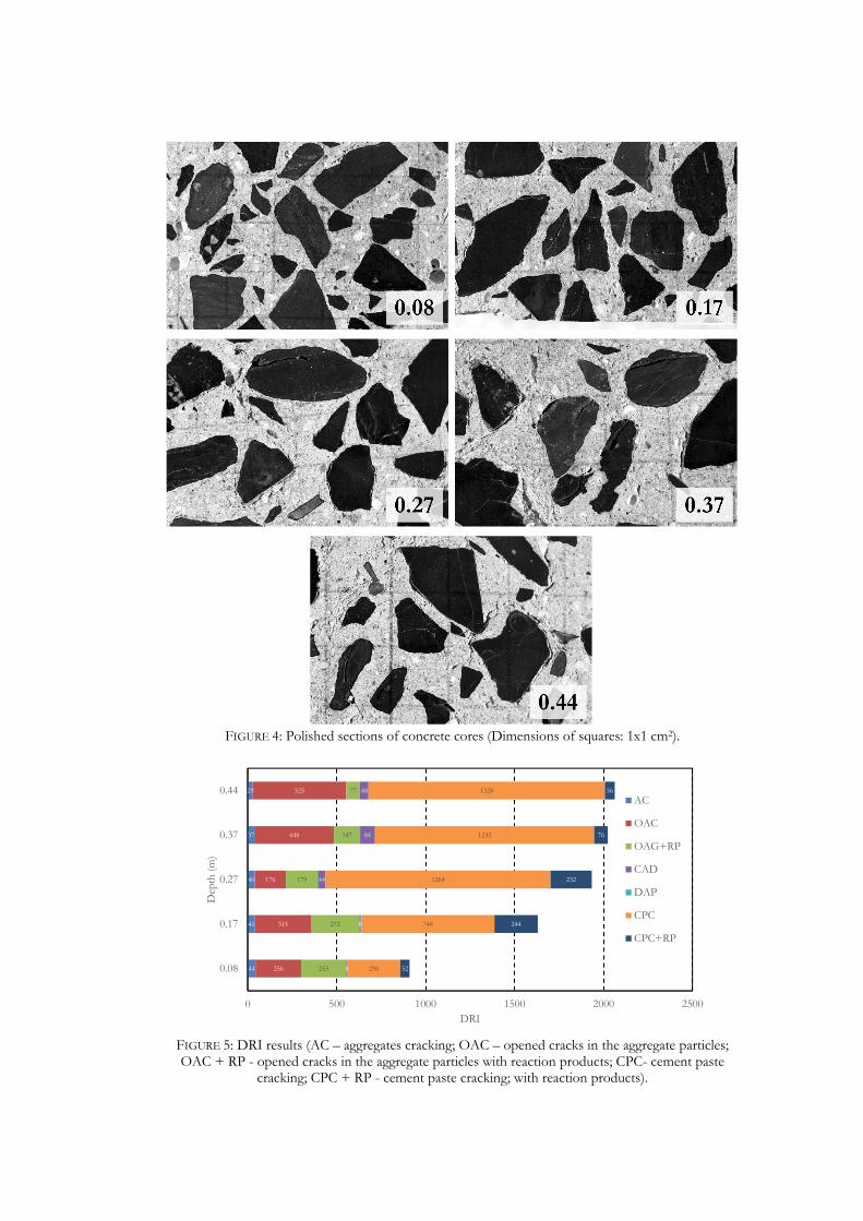
FIGURE 4: Polished sections of concrete cores (Dimensions of squares: 1x1 cm2).
FIGURE 5: DRI results (AC – aggregates cracking; OAC – opened cracks in the aggregate particles; OAC + RP - opened cracks in the aggregate particles with reaction products; CPC- cement paste
cracking; CPC + RP - cement paste cracking; with reaction products).
44
41
40
37
29
256
315
176
448
525
253
272
179
147
77
8
8
44
84
48
296
748
1264
1232
1328
52
244
232
76
56
0 500 1000 1500 2000 2500
0.08
0.17
0.27
0.37
0.44
DRI
Dep
th (m
)
AC
OAC
OAG+RP
CAD
DAP
CPC
CPC+RP

FIGURE 6: Residual expansion test results (a. dimensional monitoring; b. mass monitoring).
FIGURE 7: Superposition of free expansion curve and RE curves after applying an offset
corresponding to the assessed expansion prior to coring (error bars on the free expansion curve correspond to ± the standard deviation of the expansion measured on three identical specimens).
FIGURE 8: Evolution of SDI (for the first cycle only) (a) and of the DRI (b), as a function of the
expansion of concrete.
0.0%
0.1%
0.2%
0.3%
0.4%
0.5%
0.6%
0.7%
0 200 400 600
Exp
ansi
on (%
)
Time (days)
0.08 0.17 0.270.37 0.44
a.
0.08
0.17
0.270.370.44
0.0%
0.2%
0.4%
0.6%
0.8%
1.0%
1.2%
1.4%
1.6%
0 200 400 600
m/m
(%)
Time (days)
b.
0.08
0.17
0.370.27
0.44
0.0%
0.2%
0.4%
0.6%
0.8%
1.0%
1.2%
1.4%
1.6%
1.8%
0 100 200 300 400 500 600 700
Exp
ansi
on (%
)
Time (days)
Free expansion
RE @ 0.08 m
RE @ 0.17 m
R2 @ 0.27 m
R2 @ 0.37 m
RE @ 0.44 m
y = 113.83x - 0.631R² = 0.9574
0.3
0.4
0.5
0.6
0.7
0.8
0.9
1.0
0.90% 1.00% 1.10% 1.20% 1.30% 1.40%
SDI
(1st
cyc
le)
Assessed expansion of concrete (%)
a.
y = 265309x - 1391.6R² = 0.925
0
500
1000
1500
2000
2500
0.90% 1.00% 1.10% 1.20% 1.30% 1.40%
DR
I
Assessed expansion (%)
b.