diagnosing voice quality impairments and designing ... · interconnect devices such as hubs,...
TRANSCRIPT

White Paper
Diagnosing Voice Quality Impairments and Designing Solutions for Voice over IP Systems

White Paper Diagnosing Voice Quality Impairments and Designing Solutions for Voice over IP Systems
Executive Summary
Successful Voice over IP (VoIP) deployments can deliver solutions that provide voice quality that is comparable to traditional circuit-switched telephone networks, but at a lower cost. Building on the background information provided in Overcoming Barriers to High-Quality Voice over IP Deployments — http://www.dialogic.com/goto/?8539, this paper covers in detail impairments such as delay, jitter, packet loss, and echo in Ethernet-based VoIP implementations. It also discusses choosing CODECs, provisioning networks to support VoIP, and working with interconnect devices such as hubs, bridges, switches, and routers.
Diagnosing Voice Quality Impairments and Designing Solutions for Voice over IP Systems White Paper
1
Table of ContentsIntroduction .......................................................................................................... 2
Definitions ............................................................................................................. 2
VoIP Protocols and Network Technologies ...................................................... 2
Ethernet Media Access Control ...................................................................... 2
Packet Loss .......................................................................................................... 3
Collision Domains and Connection Devices ........................................................... 4
Hubs ............................................................................................................. 4
Bridges .......................................................................................................... 4
Switches ........................................................................................................ 4
Routers .......................................................................................................... 4
Examples ....................................................................................................... 5
Jitter ..................................................................................................................... 7
Jitter Buffers .................................................................................................. 8
Jitter and Lost Packets ................................................................................... 9
Collisions and Local Area Network Load .............................................................. 10
Shared Ethernet .......................................................................................... 10
Half-Duplex Switched Ethernet ................................................................... 10
Full-Duplex Switched Ethernet .................................................................... 10
Subjective Effects ................................................................................................ 10
Clock Drift and Synchronization ......................................................................... 10
CODECs ............................................................................................................. 11
Waveform CODECs ...................................................................................... 11
Source CODECs ........................................................................................... 11
CODECs and DTMF ..................................................................................... 12
CODECs and Network Throughput ............................................................... 12
CODECs and Capacity Planning ................................................................... 13
Gain Characteristics and Voice Quality ................................................................ 14
Echo ................................................................................................................... 16
Acoustic Echo .............................................................................................. 16
Hybrid Echo ................................................................................................ 16
Echo Cancellation and Suppression ............................................................. 18
Latency and Interconnect Devices ....................................................................... 19
Hubs .................................................................................................................. 19
Bridges and Switches .......................................................................................... 19
The Challenge of Providing High Voice Quality .................................................... 20
References ......................................................................................................... 21
Appendix A. Additional Capacity Planning Information ........................................ 22
Appendix B. Voice over IP Components from Dialogic ......................................... 25
For More Information .......................................................................................... 26

Introduction
VoIP is a lower cost alternative to circuit-switched telephony technology, with an equivalent level of service. However, identifying the cause of poor voice quality in VoIP has proven challenging, and part of the challenge is in categorizing defects and understanding the symptoms associated with various impairments such as packet loss, jitter, and echo.
The delivery of high-quality voice must be designed into VoIP solutions from the beginning to ensure success. Choosing the best CODECs for specific network conditions and provisioning each network correctly for VoIP are especially important.
Definitions
Before describing the problems that must be overcome in creating high-quality VoIP service, some basic technology must be discussed.
VoIP Protocols and Network Technologies
VoIP is based on the Internet Protocol (IP), an unreliable, best-effort, connectionless packet delivery system. Although Transmission Control Protocol (TCP) provides more reliable delivery of packets than IP, it is not optimized for data that must be transported with very low latency such as real-time voice. User Datagram Protocol (UDP) is a less complex alternative to TCP, but the UDP is also unreliable and does not utilize acknowledgements, order incoming messages, or attempt to control the rate at which information flows between two systems. However, UDP consumes much less network bandwidth than TCP and is comparatively better suited for real-time voice transmission over IP.
The Real-Time Transport Protocol (RTP) is used in conjunction with UDP so that incoming messages can be reconstructed in the same order in which they were sent. RTP is also used to specify the format of the data, the source of the data, and relative timestamps. RTP is encapsulated in the data area of a UDP packet and is subject to the same constraints as UDP. Another protocol, Real-Time Transport Control Protocol (RTCP), is used to exchange reports about the quality of the RTP session being used by VoIP endpoints.
Several Local Area Network (LAN) technologies are available today. The most common are Ethernet, Asynchronous Transfer Mode (ATM), Fiber Distributed
Data Interface (FDDI), and Token Ring. This paper discusses VoIP for Ethernet-based LANs and assumes the use of RTP.
VoIP traffic will travel over a Wide Area Network (WAN) when two endpoints are separated by an appropriately wide geographical distance. This distance can introduce significant delay because VoIP packets usually take different routes on the WAN to reach their destination. This paper discusses the issues involved in this kind of delay.
Ethernet Media Access Control
Ethernet technology was originally based on a bus topology that used a shared media coaxial cable (10Base-5, 10Base-2) to connect every system in an office. Such cables carried both transmit and receive data for up to 100 nodes. Other data communications standards, such as 10Base-T, 100Base-T, and 1000Base-T, utilize the same unshielded twisted pair (UTP) cabling system prevalent in communications and can be used to connect devices in a star-configuration, as shown in Figure 1. Only two nodes can be connected via the UTP cable, and the central “hub” is used to communicate with more than two nodes at one time.
Ethernet standards use an RJ-45 connector and Category 5 unshielded twisted pair (CAT-5 UTP) with separate transmit and receive data paths. Since shared media technologies require that only one node be allowed to transmit at a time, algorithms for Media Access Control (MAC) were developed (IEEE Std. 802.3).
Ethernet MAC is denoted as Carrier-Sense Multiple Access with Collision Detection (CSMA/CD) and works according to the following scenario.
When a node is ready to transmit a frame of data, it listens on the receive channel first. If the channel is quiet for a minimum amount of time (known as the Interframe Gap or IFG), the node will begin to transmit. If the channel is busy, the node monitors it until it is quiet for the equivalent time of an IFG.
Because multiple nodes can be present on the network, more than one node may simultaneously determine that the channel is free and begin to transmit at approximately the same time, resulting in a “collision” that distorts the information in both transmissions.
When transmitting, nodes must continuously monitor the receive channel to detect collisions. When a node detects a
White Paper Diagnosing Voice Quality Impairments and Designing Solutions for Voice over IP Systems
2

3
Diagnosing Voice Quality Impairments and Designing Solutions for Voice over IP Systems White Paper
collision, it stops transmitting and waits for a period of time before attempting to transmit again. The amount of time that the node waits is based on a random algorithm known as “binary exponential backoff.” The random nature of the wait time helps ensure that no two nodes are waiting for the same amount of time.
Each node will make 16 attempts to transmit data, and if it cannot transmit successfully, it will drop the packet. If a collision does not occur, the frame containing the packet will be transmitted in its entirety. Collisions are problematic because they waste network bandwidth and cause packet loss.
Packet Loss
Packets that contain voice data can be lost for several reasons: • Insufficient bandwidth due to poor capacity planning • Packets arriving at their destination too late • Network outages
The system designer must ensure that a network has the capacity to meet the bandwidth requirements of voice traffic. In doing so, the designer should consider the aggregate bandwidth requirements of all the communications that are taking place on a network. If the underlying network does not have sufficient bandwidth, it is said to be “oversubscribed.” In some cases, it may be necessary to dedicate a LAN to VoIP to avoid this condition.
A simple example can illustrate the basic methodology
used in determining network requirements for voice traffic.
Suppose a network has a data rate of 100 Mbps, and each
RTP packet on the network contains 30 milliseconds
(msec) of voice in 24 bytes of data. Overhead for RTP,
UDP, IP, and Ethernet processing adds 78 bytes, resulting
in a 102-byte Ethernet frame, which is repeated every
30 msec. Assuming ideal conditions, the network could
support 3676 channels of voice according to the following
formula:
(100 x 106 bits/sec)/(102 bytes/sample/channel x 8 bits/
byte) x (30 msec/sample) = 3676 channels
If more than 3676 channels attempted to use this network
simultaneously, the network would be
oversubscribed.
The example shown above is for illustration purposes
only, and should not be used for real-world network
capacity planning. An analysis of many of the complex
issues affecting such planning for VoIP will be presented
throughout the remainder of this paper.
Oversubscription can lead to lost packets. The probability
of CSMA/CD detecting a channel that is “free” for
transmission decreases as more devices use the network.
As described above, the IP layer will make 16 attempts to
transmit a packet, but if the network is never free, it will
discard the packet, causing packet loss.
Node
Node
NodeNode CentralHub
Figure 1. Star Topology

Collision Domains and Connection Devices
A collision domain is the group of nodes that would create
a collision if they transmitted simultaneously, resulting in
packet loss. Figure 1 illustrates a collision domain, and one
of four types of devices can be used as the “central hub”:
hubs, bridges, switches, and routers. Each of these devices
affects the collision domain and packet loss differently.
Hubs
Hubs are multi-port repeaters that operate at the OSI
Physical Layer (Layer 1). They repeat the data they receive
without modification, and they are transparent to higher
layer protocols and network devices.
Since a hub forwards the data that it receives on one port
to all ports connected to it, all the devices receive the same
data and share the media from a logical point of view.
Although the nodes attached to the hub are not physically
connected to each other via a shared bus, they are all part
of the same collision domain. CSMA/CD is necessary
when using a hub because data from two simultaneously
transmitting devices could easily collide.
Bridges
Bridges are OSI Data Link Layer (Layer 2) devices used to
connect LANs. These LANs appear to upper layer protocols
as a single LAN.
Bridges do not extend the collision domain in the same way
as hubs do. A bridge inspects the Layer 2 information it
receives on one port and only forwards a frame to another
port if the frame has a correct destination address. It does
not modify the forwarded data in any way. If the bridge
does not know the destination port, it will send the frame
to all ports (except for the transmitting port).
Bridges are also used to connect segments that have
different speeds, such as 10 Mbps and 100 Mbps Ethernet.
Translation bridges can be used to connect dissimilar LANs
(that is, Ethernet and FDDI).
Switches
The earliest bridges were two-port devices, and when
equipment manufacturers started designing intelligent
multi-port bridges, they became known as switches. Bridges
and switches are very similar, and share the same collision
domain characteristics.
Bridges are typically store-and-forward devices. They store
the frame and forward it when the destination port is free.
Switches also use store-and-forward, but may support cut-
through forwarding, where forwarding takes place as soon
as the destination address is determined. Modified cut-
through forwarding sends the frame after the first 64 bytes
of data have been received.
The presence of a switch does not guarantee that the
network is full duplex. Even though CAT-5 wiring and
point-to-point connections are prerequisites to full-duplex
operation and are included in switch devices, many nodes
continue to run the CSMA/CD algorithm, which is
inherently half duplex.
Because full-duplex/flow-control standards (IEEE 802.3x)
exist that do not use CSMA/CD, full-duplex operation
is possible in a switch environment if the physical trans-
mission medium and nodes are full-duplex capable.
Full-duplex operation effectively doubles the bandwidth of
the network.
Routers
Routers are OSI Network Layer (Layer 3) devices that
are typically used to link WAN networks together. WAN
traffic can travel on different routes, and routers determine
the fastest or cheapest-cost route.
Bridges and switches use MAC addresses (Layer 2
information) in frames, while routers use network addresses
(Layer 3 information) in packets to make forwarding
decisions. Routers do not extend the collision domain.
Routers are also used to connect similar or dissimilar LANs
(that is, Ethernet and FDDI). Typically, routers require
more configuration than bridges and switches.
White Paper Diagnosing Voice Quality Impairments and Designing Solutions for Voice over IP Systems
4
5
Diagnosing Voice Quality Impairments and Designing Solutions for Voice over IP Systems White Paper
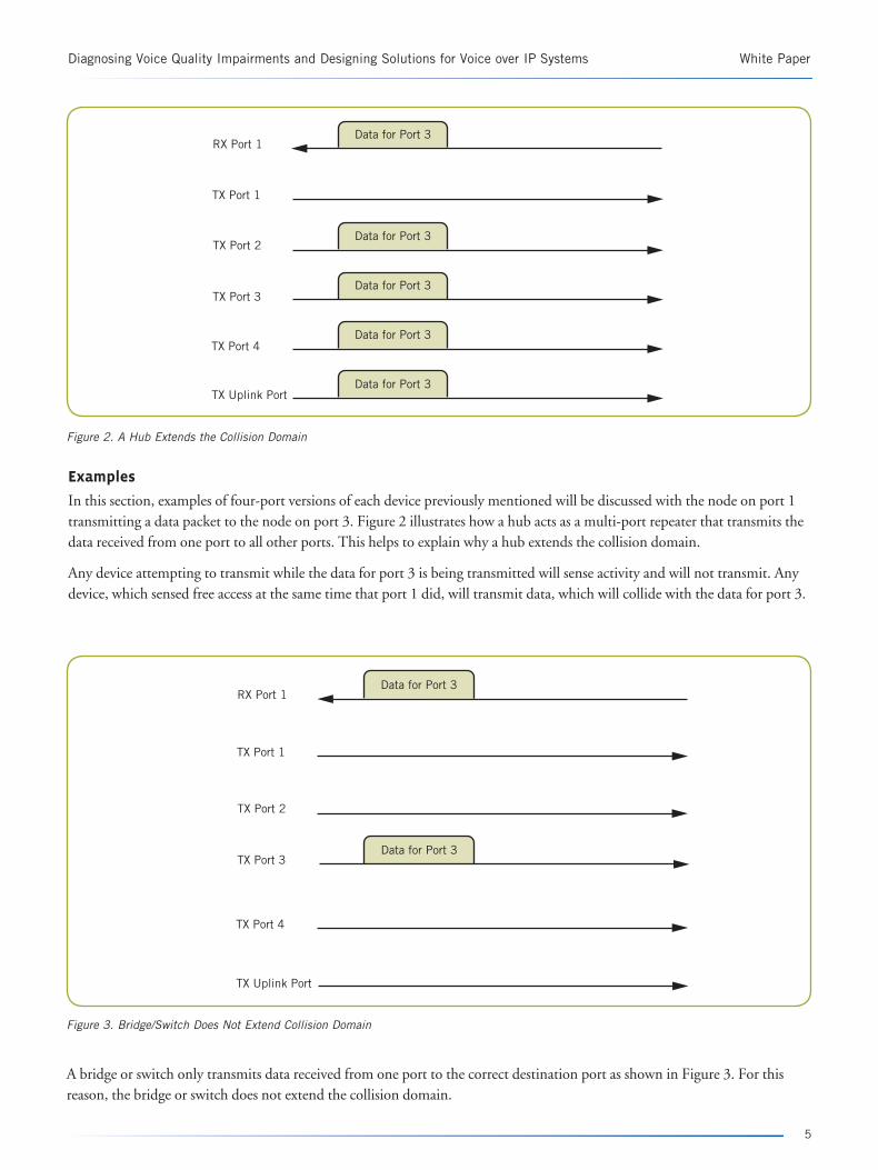
Examples
In this section, examples of four-port versions of each device previously mentioned will be discussed with the node on port 1 transmitting a data packet to the node on port 3. Figure 2 illustrates how a hub acts as a multi-port repeater that transmits the data received from one port to all other ports. This helps to explain why a hub extends the collision domain.
Any device attempting to transmit while the data for port 3 is being transmitted will sense activity and will not transmit. Any device, which sensed free access at the same time that port 1 did, will transmit data, which will collide with the data for port 3.
Data for Port 3
Data for Port 3
Data for Port 3
Data for Port 3
Data for Port 3
RX Port 1
TX Port 1
TX Port 2
TX Port 3
TX Port 4
TX Uplink Port
Figure 2. A Hub Extends the Collision Domain
Data for Port 3
Data for Port 3RX Port 1
TX Port 1
TX Port 2
TX Port 3
TX Port 4
TX Uplink Port
A bridge or switch only transmits data received from one port to the correct destination port as shown in Figure 3. For this reason, the bridge or switch does not extend the collision domain.
Figure 3. Bridge/Switch Does Not Extend Collision Domain
White Paper Diagnosing Voice Quality Impairments and Designing Solutions for Voice over IP Systems
6
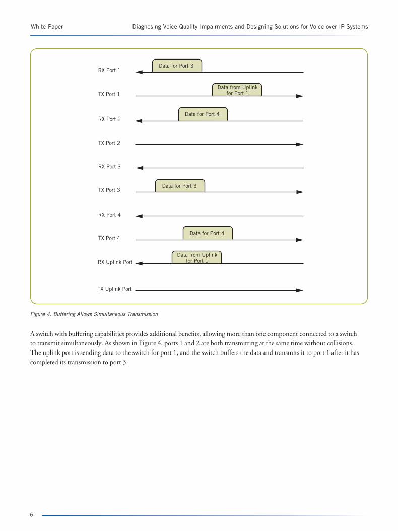
A switch with buffering capabilities provides additional benefits, allowing more than one component connected to a switch to transmit simultaneously. As shown in Figure 4, ports 1 and 2 are both transmitting at the same time without collisions. The uplink port is sending data to the switch for port 1, and the switch buffers the data and transmits it to port 1 after it has completed its transmission to port 3.
Data for Port 3
Data from Uplinkfor Port 1
Data for Port 4
Data for Port 3
Data for Port 4
Data from Uplinkfor Port 1
RX Port 1
TX Port 1
RX Port 2
TX Port 2
RX Port 3
TX Port 3
RX Port 4
TX Port 4
RX Uplink Port
TX Uplink Port
Figure 4. Buffering Allows Simultaneous Transmission

7
Diagnosing Voice Quality Impairments and Designing Solutions for Voice over IP Systems White Paper
4 3 2 1 4 3 2 1
“We did not receive your payment” “We did not receive your payment”
Packets arrive in order without delaysTime is constant between arrival of each packet
Figure 5. Ideal Packet Movement – Without Jitter
Jitter
RTP is essentially a continuous stream of voice data that is transmitted in discrete packets. In an ideal VoIP scenario, packets traveling between points A and B would never be lost, always arrive in the same order as transmitted, always follow the same path, and always take the same amount of time to cross the network. Figure 5 illustrates an ideal voice packet transmission and reception scenario.
White Paper Diagnosing Voice Quality Impairments and Designing Solutions for Voice over IP Systems
8
4 3 2 1
“We did not receive your payment” “We did not re..................ceive.................your payment”
Packets arrive in order with delaysTime varies between arrival of each packet
4 3 2 1
Figure 6. “Real-World” Packet Movement with Jitter
“We did not receive your payment” “We did not.........................payment...............receive your”
Packets arrive out of order with delaysTime varies between arrival of each packet
3 4 2 14 3 2 1
Figure 7. Delays Cause Jitter and Out-of-Order Arrival
Jitter Buffers
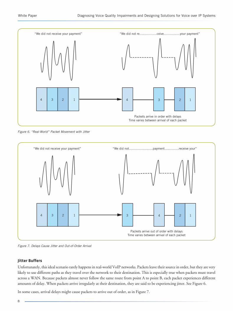
Unfortunately, this ideal scenario rarely happens in real-world VoIP networks. Packets leave their source in order, but they are very likely to use different paths as they travel over the network to their destination. This is especially true when packets must travel across a WAN. Because packets almost never follow the same route from point A to point B, each packet experiences different amounts of delay. When packets arrive irregularly at their destination, they are said to be experiencing jitter. See Figure 6.
In some cases, arrival delays might cause packets to arrive out of order, as in Figure 7.
9
Diagnosing Voice Quality Impairments and Designing Solutions for Voice over IP Systems White Paper
“We did not receive your payment” “We did not receive your payment”
Jitter bufferPackets arrive out of order with delaysTime varies between arrival of each packet
3 4 1 24 3 2 1 4 3 2 1
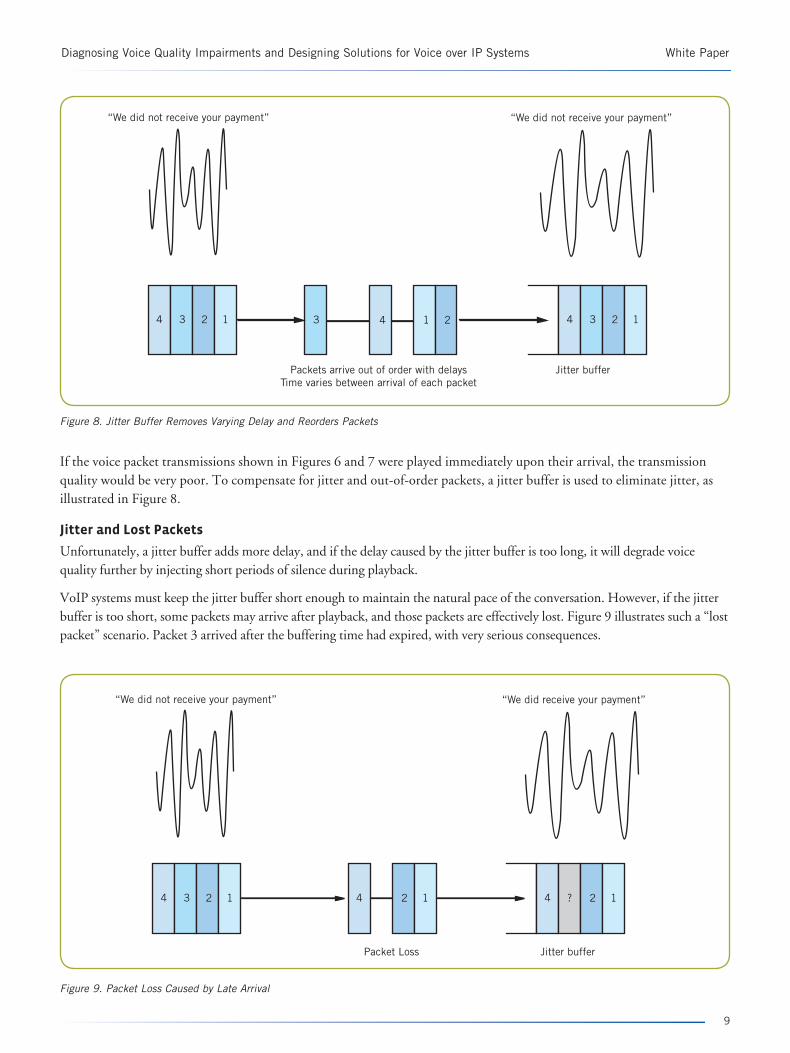
Figure 8. Jitter Buffer Removes Varying Delay and Reorders Packets
“We did not receive your payment” “We did receive your payment”
Jitter bufferPacket Loss
4 3 2 1 4 2 1 4 ? 2 1
Figure 9. Packet Loss Caused by Late Arrival
If the voice packet transmissions shown in Figures 6 and 7 were played immediately upon their arrival, the transmission quality would be very poor. To compensate for jitter and out-of-order packets, a jitter buffer is used to eliminate jitter, as illustrated in Figure 8.
Jitter and Lost Packets
Unfortunately, a jitter buffer adds more delay, and if the delay caused by the jitter buffer is too long, it will degrade voice quality further by injecting short periods of silence during playback.
VoIP systems must keep the jitter buffer short enough to maintain the natural pace of the conversation. However, if the jitter buffer is too short, some packets may arrive after playback, and those packets are effectively lost. Figure 9 illustrates such a “lost packet” scenario. Packet 3 arrived after the buffering time had expired, with very serious consequences.
White Paper Diagnosing Voice Quality Impairments and Designing Solutions for Voice over IP Systems
10
Receivers have algorithms that interpolate and compensate for packet loss. However, the algorithm may not work perfectly, and the listener may perceive degraded voice quality.
Collisions and Local Area Network Load
Compensating for the occasional lost packet is relatively easy, but compensating for the loss of several consecutive packets is much more difficult. Because multi-packet loss typically occurs during peak network traffic in “bursts,” paying careful attention to network load conditions is very important.
A lightly loaded shared Ethernet network is normally defined as one that is utilized between 0 and 50% with latencies of about 0.001 to 0.01 seconds [Breyer, pp. 287-8]. On such a network, few collisions generally occur (less than 10%), and it is very probable that the packets involved in the collisions will be successfully transmitted during a second attempt.
As network utilization increases beyond 50% and up to 80% (a moderate to heavy load), the chance of collisions is much greater, latency rises to about 0.01 to 0.1 seconds, and the overall throughput of the network decreases. Fewer packets containing information arrive at their destinations, and such conditions can have a severe negative impact on voice quality. Little can be done to compensate for the loss of five or more consecutive voice packets in a stream.
The situation worsens as a network approaches saturation with utilization greater than 80%. Under such conditions, latency can exceed a full second.
The amount of utilization that can be tolerated by VoIP applications depends on the type of network in use. Some general recommendations are given below.
Shared Ethernet
VoIP applications should work best in shared Ethernet networks with an average of 30% utilization. As a guideline, 5% of the 30% is utilized by RTCP and the remainder of the 30% is utilized by RTP. This allows for momentary peak utilizations that exceed 50%.
Half-Duplex Switched Ethernet
Half-duplex switched Ethernet is still shared, but the potential for collisions is greatly reduced since only two nodes compete for the media at the same time. VoIP applications should work well in half-duplex Ethernet networks with an average utilization of 70%.
Full-Duplex Switched Ethernet
Full-duplex switched Ethernet eliminates contention for the
media and does not use CSMA/CD. Because no collisions
take place, VoIP applications should work well with an
average utilization of 80%.
Subjective Effects
High jitter and lost packets can cause several negative effects: • Voice transmissions can sound unnatural or robotic.
• Extended periods of silence or gaps in the signal can occur.
• Excessive clicking or popping sounds may be heard.
DTMF signaling tones may be transmitted via RTP, but
lost packets and excessive jitter can cause these tones to
become distorted. Multiple digits could be detected at the
receiving end when only a single digit was transmitted. In
some cases, the tones can become so distorted that they will
not be understood at the receiving end.
Clock Drift and Synchronization
Clock drift can be another source of voice quality problems.
Excessive clock drift can cause overrun of a jitter buffer or
introduce additional delays. • If the clocks of the receiver and transmitter are too far
out of synchronization, the transmitter may fill the receive buffer faster than the receiver can process the data (overrun).
• The receiver may have to wait for a slow transmitter, causing unnecessary delay.
Clock drift can cause the same type of problems as packet
loss and delay. The listener can perceive the voice signal
as unnatural or robotic, perceive gaps in the audio, or
experience excessive clicking or popping. The receiver may
detect multiple DTMF digits when the transmitter sent
only a single digit.
Synchronization is important in insuring that VoIP
endpoints use the same references for timestamps. The
Network Time Protocol (NTP) [RFC 1305] defines the
mechanisms that network components should use to
synchronize time. Such synchronization is necessary for
billing integrity, accurate logging and tracing, and the
proper initialization of the NTP timestamp fields contained
in RTCP sender reports.

11
Diagnosing Voice Quality Impairments and Designing Solutions for Voice over IP Systems White Paper
CODECs
A knowledge of CODECs is necessary for a complete understanding of network capacity planning analysis. Voice is an analog signal that must be converted to a digital signal for transmission over a digital network. Converting analog to digital is called encoding, and converting digital to analog is called decoding. A CODEC (encoder/decoder) is used to convert in both directions.
Two types of CODECs are available: waveform and source. Source CODECs reduce bandwidth requirements, and produce lower but still acceptable speech quality.
Waveform CODECs
Waveform CODECs attempt to encode and decode a signal without any knowledge of how a signal was originally generated, for example, whether or not the source was a human being. Waveform CODECs typically run at higher bit rates than source CODECs and can consume more network bandwidth. However, they often produce the most accurate rendering of the original signal. G.711 and G.726 are the popular waveform CODECs.
G.711A G.711 encoded audio stream is a 64 Kbps bitstream. Each sample of the original signal is encoded in 8 bits or an octet. By convention, a frame of G.711 encoded data consists of eight 125 µs (that is, 1 msec). Dialogic® products process G.711 frames of 10, 20, or 30 msec. G.711 can typically achieve a Mean Opinion Score (MOS) of 4.2, a high satisfaction rating. MOS can range from 1 (bad) to 5 (excellent). See Overcoming Barriers to High-Quality Voice over IP Deployments for more information about MOS.
G.726Because G.726 uses Adaptive Differential Pulse Code Modulation (ADPCM) to encode G.711 coding in two, three, or four bits, G.726 encodes data at 16, 24, 32, or 40 Kbps. By convention, a frame of G.726 encoded data is also 125 usec in length. Dialogic products process G.726 frames of 10, 20, or 30 msec.
Source CODECs
Source CODECs use a model that takes into account the source of the original signal, for example, the human vocal tract. Human speech is very complex, and the model has to take into account the dynamic state of the vocal cords, the movement of the mouth and tongue, and voiced, unvoiced, and plosive speech sounds.
The models consider the vocal tract as a time-varying filter that is excited with a white noise source for unvoiced speech segments, or with a train of pulses separated by a pitch period for voiced speech segments. Algorithms encode the filter specification (a flag specifies voiced or unvoiced), the variance of the excitation signal, and a pitch period for voiced speech.
G.723.1, G.729, and GSM-EFR are popular source CODECs.
G.723.1G.723.1 encodes 30 msec of speech in one of two modes (6.4 Kbps or 5.3 kpbs), which can change dynamically on a per-frame basis. The 6.4 kpbs mode uses Multi-Pulse-Maximum Likelihood Quantization (MP-MLQ) to model the voice signal and can achieve a MOS of 3.9. The 5.3 Kbps mode uses Algebraic-Code-Excited Linear Prediction (ACELP) and can achieve a MOS of 3.7.
G.723.1 uses a “lookahead” algorithm, which “looks ahead” at the samples immediately after the samples currently being encoded and adds 7.5 msec of processing time. The total processing time for a single frame is then 37.5 msec.
G.723.1 Annex G.723.1 Annex A supports Voice Activity Detection (VAD), Discontinuous Transmission (DTX), and Comfort Noise Generation (CNG) to reduce network utilization during periods of silence. The VAD algorithm makes voice activity detection decisions that are based on long-term averages of received speech packets. DTX algorithms are invoked when VAD determines that speech is absent.
Non-active voice frames, which contain information on background noise, can be encoded with only four bytes of data. Such frames are not sent continuously, but only when a significant change in background noise has been detected. On the decoder side, if VAD determines that the frame does not contain voice, CNG produces non-active voice frames for comfort noise generation.
Packet loss can cause the G.723 encoder and decoder to become unsynchronized, and it can take many frames to recover. Packet loss also interferes with VAD and subsequently impacts DTX and CNG performance.
Dialogic products support G.723.1 and G.723.1A (Annex A) with 1 to 4 frames per packet. G.723.1A is used when an application specifies VAD. In addition, Dialogic products support G.723.1 Annex C.

White Paper Diagnosing Voice Quality Impairments and Designing Solutions for Voice over IP Systems
G.729G.729 encodes 10 milliseconds of speech at a rate of 8 Kbps with a lookahead of 5 msec. G.729 uses Conjugate Structure ACELP (CS-ACELP) to model the voice signal and can achieve a MOS of 4.0.
The effect of packet loss on the G.729 is similar to its effect on G.723.1.
Dialogic products support G.729, G.729A (Annex A), G.729B (Annex B), and G.729A+B (Annex A and B). G.729A is a less complex version of G.729. G.729B adds support for VAD, DTX, and CNG. Some Dialogic products support G.729 with 1 to 4 frames per packet, while others only support 3 to 4 frames per packet. G.729 and G.729A are used when VAD is not specified. G.729B and G.729A+B are used when VAD is specified.
GSM-EFRGSM-EFR (enhanced full rate) encodes 20 milliseconds of speech at a rate of 12.2 Kbps. It uses ACELP and can achieve a MOS of 4.4.
GSM-EFR has options for VAD, DTX, and CNG; and Dialogic products support GSM-EFR at 1 to 3 frames per packet.
CODECs and DTMF
Many VoIP solutions must be capable of sending and receiving tone and multi-tone signals such as DTMF. Waveform CODECs will not distort DTMF when it is transmitted in-band. Source CODECs, on the other hand, were designed to encode and decode speech, and the accurate encoding and decoding of DTMF tones would require a different source model. For this reason,
source CODECs are likely to distort DTMF, when it is transmitted in-band. System designers should use out-of-band signaling techniques, such as rfc2833 or H.245 UII, for DTMF and call progress tones when using source CODECs for voice.
CODECs and Network Throughput
Throughput is the percent of network traffic that is application data.
Figure 10 shows how an Ethernet frame is constructed. The RTP datagram is carried in the data area of the UDP datagram, which is, in turn, carried in the data area of the IP datagram. The IP datagram is encapsulated within the Ethernet frame with the required IFG.
Table 1 provides important information about the Ethernet frame for various CODECs. Note the “Efficiency” and “Voice Packet Efficiency” columns at the far right.
• Efficiency — Ratio of the size of the data to the size of the entire frame (size of data/size of frame)
• Voice Packet Efficiency — Ratio of milliseconds of transmitted voice to the size of the entire frame (size of voice sample/size of frame)
The “Voice Packet Efficiency” column illustrates the effectiveness and efficiencies associated with low bit-rate CODECs. G.723.1 has a much higher efficiency value than G.711 at three frames per packet (65.22% compared to 9.43%), which means that more voice data can be transmitted in the same amount of time. Higher efficiency also reduces the load on the network. However, because G.723.1 has a lower MOS than G.711 (3.7 to 4.2), better network throughput comes at the expense of voice quality.
12
IP
Ethernet Frame IFG
22 20 8 12 N VoiceSamples
4CRC 12
RTP
UDP
Figure 10. Encapsulation of RTP in the Ethernet Frame

13
Diagnosing Voice Quality Impairments and Designing Solutions for Voice over IP Systems White Paper
CODECs and Capacity Planning
Every CODEC has different network utilization needs because the combination of CODEC, frame size, frames per packet, and VAD directly correlate to the number of RTP sessions that can be supported on a given network.
Frame size controls the voice packet generation frequency (how many packets per second will be generated by a CODEC). RTP data is the encoded data, which is encapsulated in the RTP, UDP, and IP datagrams in the Ethernet frame as shown in Figure 10. The size of the Ethernet VoIP frame equals the size of the RTP data plus the 78-byte overhead (from RTP, UDP, IP, Ethernet headers, IFG, etc.).
Capacity Planning Formula When preparing to add VoIP to a LAN segment, system designers should ascertain the utilization of the segment without VoIP, and then add VoIP utilization requirements to determine total utilization. System designers should also determine the network’s peak usage levels and the times when peak usage occurs. The following formula can be used to determine the VoIP utilization requirements for a given number of identical RTP sessions (channels) on a full-duplex network where the VoIP connection is bidirectional (not multicast or unidirectional) and VAD is not in use.
% Utilization = 8 X [78 + (RD X FPP)] X1000 X (C)/ BR X VFS X FPP)
where • 8 = bits per byte • 78 = bytes of overhead per voice frame • RD = RTP data = bytes of voice data per voice frame
• FPP = voice frames per packet • 1000 = milliseconds per second • C = number of channels • BRN = bit rate of network (10 Mbps for 10Base-T,
100 Mbps for 100 Base-T, 1000 Mbps for 1000Base-T)
• VFS = voice frame size
Frame size is directly related to voice packet generation
frequency (that is, how many packets per second a
CODEC will generate).
If the formula above is applied to a half-duplex network,
the result must be divided by two to account for the two
RTP streams that comprise a bidirectional VoIP call. A full-
duplex connection is strongly recommended when working with a product that aggregates multiple VoIP calls.
See Figure 11 for a graph of the utilization and number
of channels for G.711 on switched full-duplex 100Base-T
networks. For similar graphs for G.723 and G.729, see
Figures 17 and 18 respectively in Appendix A. Additional Capacity Planning Information. Appendix A also contains information that can help with capacity planning for
10Base-T (Table 6), 100Base-T (Table 7), and 1000
Base-T networks (Table 8).
Effects of VAD on Capacity PlanningWhen a CODEC supports VAD, the number of
channels in use can be increased because only about
35% of a conversation contains speech while the rest of a conversation consists of pauses in speech or silent periods.
CODEC Attribute MOS
Size of Data Size of Frame Voice Sample Efficiency
Voice Packet (octets) (octets) Size (msec) Efficiency
G.711 10 msec 4.2 80 158 10 50.63% 6.33%
G.711 20 msec 4.2 160 238 20 67.23% 8.40%
G.711 30 msec 4.2 240 318 30 75.47% 9.43%
G.723.1 5.3 Kbps, 1 f/p 3.7 20 98 30 20.41% 30.61%
G.723.1 5.3 Kbps, 2 f/p 3.7 40 118 60 33.90% 50.85%
G.723.1 5.3 Kbps, 3 f/p 3.7 60 138 90 43.48% 65.22%
G.723.1 6.3 Kbps, 1 f/p 3.9 24 102 30 23.53% 29.41%
G.723.1 6.3 Kbps, 2 f/p 3.9 48 126 60 38.10% 47.62%
G.723.1 6.3 Kbps, 3 f/p 3.9 72 150 90 48.00% 60.00%
G.729 1 f/p 4.0 10 88 10 11.36% 11.36%
G.729 2 f/p 4.0 20 98 20 20.41% 20.41%
G.729 3 f/p 4.0 30 108 30 27.78% 27.78%
Table 1. Ethernet Frame for Various CODECs

White Paper Diagnosing Voice Quality Impairments and Designing Solutions for Voice over IP Systems
VAD can also lower the bandwidth consumed during a session. G.723.1 only needs four bytes of data to describe the characteristics of silent periods, and these four bytes are encapsulated in the RTP, UDP, and IP datagrams within the Ethernet frame in the same way as speech is (see Figure 10). Therefore, an overhead of 78 bytes must be added to the 4 bytes of data resulting in an 82-byte Ethernet frame. G.729 only needs two bytes of data, resulting in an 80-byte frame.
Information about silence is only sent when changes to the
background noise are detected (DTX).
Table 2 summarizes the potential increase in capacity when using VAD, assuming a conservative ratio of 50:50 voice/silence and a switched Ethernet full-duplex 100Base-T network.
The results in Table 2 show that a 5% to 24% increase in capacity can be achieved if all channels are using VAD and G.729. The percent increase is the same regardless of the data rate of the network.
A system designer must consider the impact on inter-
operability of a VAD-only design. The CODEC and its
attributes (such as VAD) are negotiated during the setup
of a VoIP call. Typically, an endpoint advertises support
for several CODECs. An application could only advertise
VAD-enabled CODECs, but such a strategy would limit
interoperability. Realistically, most VoIP systems use a
variety of CODECs with and without VAD.
Gain Characteristics and Voice Quality
As a signal moves from one component to another, it may
“gain” strength. The overall gain between any two points is the sum of the gain of each component between the two
points. Since a VoIP solution can bridge analog and digital
networks and handset devices, a system designer should consider the gain characteristics of each device to ensure
that amplification does not cause distortion.
Looking at how Dialogic products deal with gain provides
a good example of how gain works. Dialogic products
communicate via an internal time division multiplex
14
120.00
100.00
80.00
60.00
40.00
20.00
0.000 100 200 300 400 500 600 700 800 900 1000 1100 1200 1300
Number of Channels
% Utilization vs Number of Channels Using G.711Switched Ethernet Full-Duplex 100BASE-T
10 ms20 ms30 ms
% U
tiliz
atio
n
Figure 11. Utilization versus Number of Channels for G.711

15
Diagnosing Voice Quality Impairments and Designing Solutions for Voice over IP Systems White Paper
(TDM) bus, and the gain characteristics of each component are measured in respect to the TDM bus. Components may interface with a digital (T-1/E-1) circuit-switched network, an analog circuit-switched network, station sets, an IP network, and/or voice record/playback devices. Each component has its own adjustable gain characteristics in transmit and receive modes, and is limited in the amount of gain it can apply. Each component also has maximum signal limits. See Figure 12 for an illustration.
CODEC Frame size
Frames/packet RTP Data Silence Data Without VAD With VAD % Increase
(msec) (bytes) (bytes) (80% utilization) (80% utilization) using VAD
G.723.1 5.3kb 30 1 20 4 3061 3359 9.74%
G.723.1 6.3kb 30 1 24 4 2941 3299 12.17%
G.729a 10 1 10 2 1136 1193 5.02%
G.729a 10 2 10 2 2040 2270 11.27%
G.729a 10 3 10 2 2777 3263 17.50%
G.729a 10 4 10 2 3389 4194 23.75%
Table 2. Capacity with and without VAD on 100Base-T Network
Analog CircuitSwitched PSTN
Interface
Analog PSTNNetwork
Digital CircuitSwitched PSTN
Interface
Digital PSTNNetwork
IP Network
Internal TDM Bus IP Interface
0 to 11dBm Gain
-19 dBm Maximum Output
0 to 11dBm Gain
-19 dBm Maximum Output
VoiceDevice
Interface
VoiceRecordings
0 to
11d
Bm G
ain
-19
dBm
Max
imum
Out
put
0 to 1
1dBm
Gain
-19
dBm M
axim
um O
utpu
t
0 to 11dBm Gain
-19 dBm M
aximum
Output
Station SetInterface
Station Set
Figure 12. Gain Characteristics in a System
Signals can also be attenuated (lowered) to a level that makes them incomprehensible.
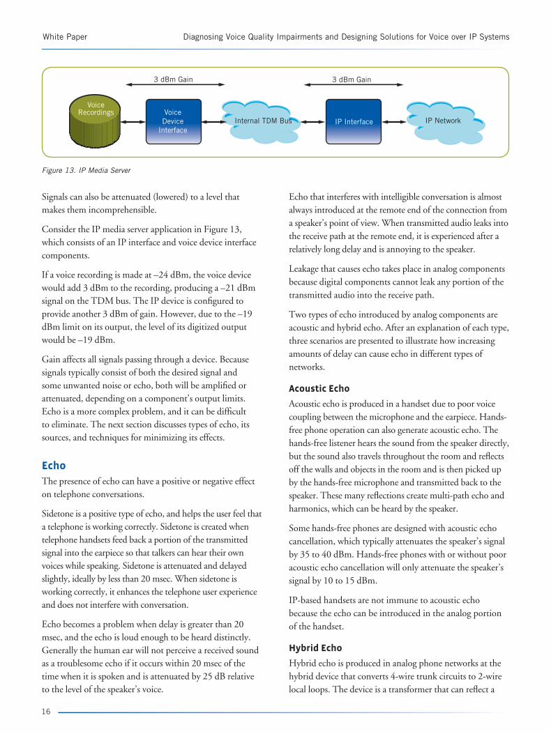
Consider the IP media server application in Figure 13, which consists of an IP interface and voice device interface components.
If a voice recording is made at –24 dBm, the voice device would add 3 dBm to the recording, producing a –21 dBm signal on the TDM bus. The IP device is configured to provide another 3 dBm of gain. However, due to the –19 dBm limit on its output, the level of its digitized output would be –19 dBm.
Gain affects all signals passing through a device. Because signals typically consist of both the desired signal and some unwanted noise or echo, both will be amplified or attenuated, depending on a component’s output limits. Echo is a more complex problem, and it can be difficult to eliminate. The next section discusses types of echo, its sources, and techniques for minimizing its effects.
Echo
The presence of echo can have a positive or negative effect on telephone conversations.
Sidetone is a positive type of echo, and helps the user feel that a telephone is working correctly. Sidetone is created when telephone handsets feed back a portion of the transmitted signal into the earpiece so that talkers can hear their own voices while speaking. Sidetone is attenuated and delayed slightly, ideally by less than 20 msec. When sidetone is working correctly, it enhances the telephone user experience and does not interfere with conversation.
Echo becomes a problem when delay is greater than 20 msec, and the echo is loud enough to be heard distinctly. Generally the human ear will not perceive a received sound as a troublesome echo if it occurs within 20 msec of the time when it is spoken and is attenuated by 25 dB relative to the level of the speaker’s voice.
Echo that interferes with intelligible conversation is almost always introduced at the remote end of the connection from a speaker’s point of view. When transmitted audio leaks into the receive path at the remote end, it is experienced after a relatively long delay and is annoying to the speaker.
Leakage that causes echo takes place in analog components because digital components cannot leak any portion of the transmitted audio into the receive path.
Two types of echo introduced by analog components are acoustic and hybrid echo. After an explanation of each type, three scenarios are presented to illustrate how increasing amounts of delay can cause echo in different types of networks.
Acoustic Echo
Acoustic echo is produced in a handset due to poor voice coupling between the microphone and the earpiece. Hands-free phone operation can also generate acoustic echo. The hands-free listener hears the sound from the speaker directly, but the sound also travels throughout the room and reflects off the walls and objects in the room and is then picked up by the hands-free microphone and transmitted back to the speaker. These many reflections create multi-path echo and harmonics, which can be heard by the speaker.
Some hands-free phones are designed with acoustic echo cancellation, which typically attenuates the speaker’s signal by 35 to 40 dBm. Hands-free phones with or without poor acoustic echo cancellation will only attenuate the speaker’s signal by 10 to 15 dBm.
IP-based handsets are not immune to acoustic echo because the echo can be introduced in the analog portion of the handset.
Hybrid Echo
Hybrid echo is produced in analog phone networks at the hybrid device that converts 4-wire trunk circuits to 2-wire local loops. The device is a transformer that can reflect a
White Paper Diagnosing Voice Quality Impairments and Designing Solutions for Voice over IP Systems
16
IP NetworkInternal TDM Bus IP Interface
3 dBm Gain
VoiceDevice
Interface
3 dBm Gain
VoiceRecordings
Figure 13. IP Media Server

17
Diagnosing Voice Quality Impairments and Designing Solutions for Voice over IP Systems White Paper
PSTN NetworkPBX(West)
PBX(East)
AnalogTelephone (Joe)
AnalogTelephone
2-WireFXS:FXO
4-WireE&M
4-WireE&M
2-WireFXO:FXS
portion of the speaker’s transmitted voice back into the speaker’s receive path.
The amount of reflection depends on the level of impedance mismatch between the components to which the hybrid device is connected. If there is a close match between impedances, a high-quality hybrid in a PBX may attenuate the reflected portion by about 20 to 30 dB. However, in many cases the impedance mismatch is large enough to reflect more echo from a speaker’s voice back into the receive path. System designers typically assume that a hybrid device for an analog phone only reduces echo by 12 dB.
An all-digital network will not produce hybrid echo, but any network that includes analog devices will experience some level of hybrid echo. Efforts to eliminate echo have to be focused on the tail circuit at the opposite end of the network because the signals at that end experience the longest delay.
Scenario 1: Circuit-Switched PSTN Network with Analog Tail CircuitScenario 1 describes a PSTN call between two analog phone users on opposite coasts of the United States, as shown in Figure 14. The speaker (Joe) is using the phone on the left. There is a 2-4-wire hybrid device in both PBXs, and each is a potential source of echo.
Assuming a close impedance match between PBX (West) and the phone interface, any echo introduced at this point will be imperceptible to the speaker because the distance between Joe’s phone and the PBX is short enough to prevent an echo from being heard.
A much greater distance separates PBX (West) and PBX (East). Assuming that the PSTN network is fiber link and that light travels in optical fiber at 0.7 times the speed of light in a vacuum, the signal delay will be about eight microseconds per mile. The one-way propagation delay for a 2500-mile link then is about 20 msec, and the round trip delay is 40 msec. Any echo of sufficient loudness introduced at the PBX (East) end of the connection would be delayed sufficiently to cause an audible, problematic echo.
Scenario 2: Circuit-Switched PSTN T-1 Network with Analog Tail CircuitScenario 2 uses a PSTN T-1 network as shown in Figure 15. Although both PBX (West) and PBX (East) still interface to analog components locally, they now are connected with digital components on the network. These digital telephony network components cannot leak transmit signals into the receive path, but they do introduce additional delay.
Figure 14. Circuit-Switched PSTN Network with Analog Tail Circuit
AnalogTelephone (Joe)
AnalogTelephone
2-WireFXS:FXO T-1 T-1
2-WireFXO:FXS
Includes2-4-Wire Hybrid
Includes2-4-Wire Hybrid
PSTN NetworkPBX(West)
PBX(East)
Figure 15. Circuit-Switched PSTN T-1 Network with Analog Tail Circuit

White Paper Diagnosing Voice Quality Impairments and Designing Solutions for Voice over IP Systems
18
Assuming a 64-Kbps bitstream, an analog signal can be encoded into digital pulse code modulation (PCM) representation in 1 msec. Because round-trip delay is the same as in Scenario 1 and processing further increases the round-trip delay to 44 msec, any echo of sufficient loudness will be heard.
Scenario 3: VoIP Network with Analog Tail Circuit In Scenario 3, the same type of call is made as in Scenarios 1 and 2, but on a VoIP network. Joe will hear an echo because encoding and decoding voice into packets introduces additional delay (see Figure 16).
Joe’s voice can travel from his telephone to the PBX in less than 1 msec. Approximately another millisecond is needed to encode Joe’s voice signal as PCM data and transmit it to the PSTN-to-IP gateway. This is the same one-way processing delay as in Scenario 2. However, because too much network bandwidth would be consumed if the gateway transmitted packets every millisecond, it buffers 10 to 30 msec of voice data before sending an RTP packet.
If the gateway is using G.711 with a 30-msec frame size, the first packet containing Joe’s voice would leave the PSTN-to-IP gateway 32 msec after Joe starts talking.
The voice packet is now sent over the WAN across the United States to the receiving gateway, approximately 2500 miles away. If the WAN is fast and not congested, and the delays of bridges, switches, and routers are negligible, then the one-way propagation delay for a 2500-mile link will be approximately 20 msec. Total delay at this point is 52 msec, already 8 msec longer than the complete round-trip delay in Scenario 2.
The receiving gateway buffers the voice packet to compensate for jitter. If a minimum buffer depth of one packet is assumed, another 30 msec of delay occurs to
which must be added the 2 msec delay between PBX (East) and the analog phone on the far end. Total delay from speaker to listener is now 84 msec.
Because any echo introduced at the far end will be delayed by the same amount of time in each direction, the total round-trip echo delay is 2 x 84 msec or 168 msec, which far exceeds 20 msec. The IP network components will not leak portions of the transmitted voice back into the receive path, but the additional delay is large enough that any echo of sufficient amplitude will be heard by a speaker on either end.
Echo can also be a problem on an enterprise LAN. The root cause (an impedance mismatch) is the same as in the WAN scenario described above.
Echo Cancellation and Suppression
In order to minimize echo and improve perceived voice quality, engineers have developed echo cancellation and suppression algorithms. Designers typically use a DSP-based echo canceller with a digital adaptive filter. Figure 17 illustrates a simple echo canceller system with such a filter.
The adaptive filter [H(t)] estimates and predicts echo in order to eliminate it from the Send-In signal [y(t)]. The NonLinear Processor (NLP) attempts to further reduce any residual echo that remains after the cancellation done by the adaptive filter. Several metrics are used to evaluate the performance of an echo canceller. • Echo Return Loss (ERL) — Ratio of Receive-Out
and Send-In power, expressed in dB. ERL measures the Receive-Out signal loss when it is reflected back as echo in the Send-In signal. ITU-T G.168 specifies ERL at 55 dB, and echo can be attenuated by several means. For example, the hybrid provides 12 dB of ERL, the adaptive filter of the echo canceller provides 18 dB, and the nonlinear processor adds 25 dB of attenuation.
WANPBX
(West)
AnalogTelephone (Joe)
AnalogTelephone
2-WireFXS:FXO T-1 T-1
2-WireFXO:FXS
Includes2-4-Wire Hybrid
Includes2-4-Wire Hybrid
PSTNto IP
Gateway
PSTNto IP
Gateway
PBX(East)
Figure 16. VoIP Network with Analog Tail Circuit

19
Diagnosing Voice Quality Impairments and Designing Solutions for Voice over IP Systems White Paper
• Echo Return Loss Enhancement (ERLE) — Ratio of Send-In power and the power of the residual error signal [e(t)] immediately after cancellation. ERLE mea-sures the loss introduced by the adaptive filter alone.
Echo cancellers must adapt to the local tail circuit quickly,
and the difference between the approximation of echo and
the actual echo should become very small in as short a time
as possible.
Echo cancellers also must detect and adjust for double-talk
(both users speaking simultaneously) and changes in echo
paths. A primary function of echo cancellers is to return
the least amount of echo possible in the Send-Out path.
According to G.168, 55 dB of echo reduction is required.
If the network delay approaches 300 msec, echo should be
reduced by 60 dB.
Latency and Interconnect Devices
In the section Collisions and Interconnect Devices earlier
in this paper, the latency (delay) inherent in using hubs,
bridges, switches, and routers was assumed to be negligible.
However, some of these interconnect devices can add delay
to VoIP communications, and it is important to determine
if the latencies are negligible in all cases.
Hubs
Hubs are multi-port repeaters that forward data received on
one port to all other ports. Hub latencies are relatively small
and are summarized in Table 3. These delays are negligible
when compared to the 10 to 30 msec that it takes for a
CODEC to encode/decode voice.
Bridges and Switches
Bridges and switches use either store-and-forward, cut-
through, or modified cut-through forwarding techniques. • Store-and-forward — Store the entire frame before
forwarding it. Has the longest latency.
• Cut-through — Forward the frame as soon as the
destination address is determined (within the first 14
bytes of the Ethernet frame). Forwards corrupt frames.
• Modified cut-through — Combination of store-
and-forward and cut-through, which waits until the
first 64 bytes of frame data has been received before
making a forwarding decision. Because of this delay,
fewer corrupt frames will be forwarded. Modified
cut-through latencies for small frames (64 bytes) are
similar to store-and-forward latencies.
IP-PSTN Gateway
Receive In
WAN
Sent Out =Near Speech + Residual
Echo
Receive Out
H(t)Echo Path
y(t)
Send In = Near Speech + Joe EchoNLP
e(t)
H(t) H(t)
x(t)
>>
+
-
Σ
Joe SpeechTall Circuit
Figure 17. Echo Canceller Diagram
Device Type (Hub/Repeater) Maximum Delay (µs)
10Base-T ≤ 2.0
Class I 100Base-T ≤ 0.7
Class II 100Base-T ≤ 0.46
1000Base-T ≤ 0.488
Table 3. Hub/Repeater Latencies
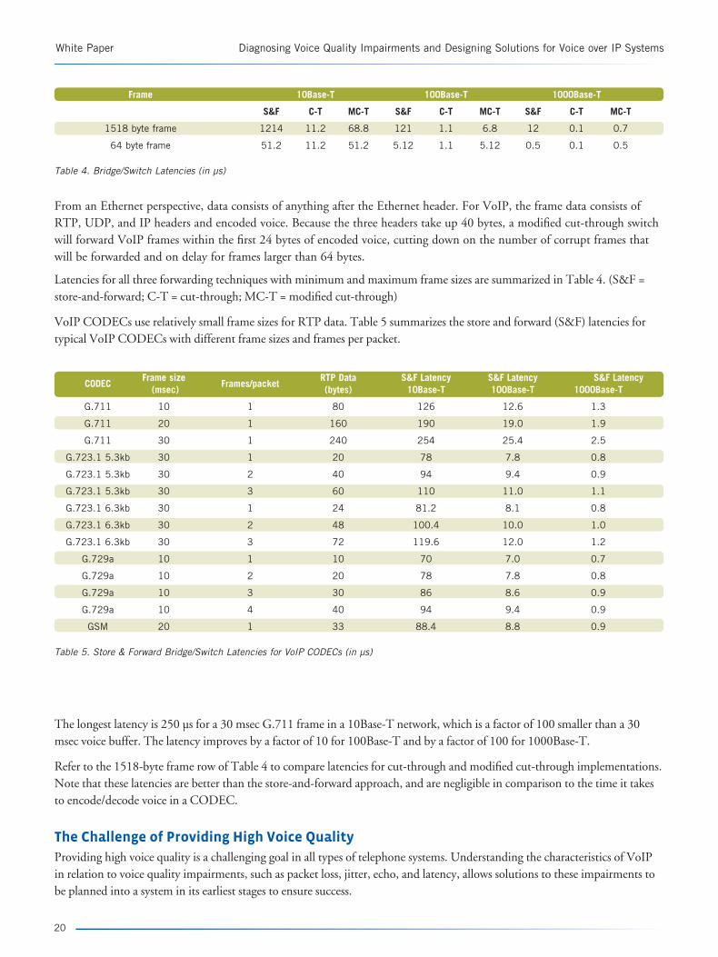
From an Ethernet perspective, data consists of anything after the Ethernet header. For VoIP, the frame data consists of RTP, UDP, and IP headers and encoded voice. Because the three headers take up 40 bytes, a modified cut-through switch will forward VoIP frames within the first 24 bytes of encoded voice, cutting down on the number of corrupt frames that will be forwarded and on delay for frames larger than 64 bytes.
Latencies for all three forwarding techniques with minimum and maximum frame sizes are summarized in Table 4. (S&F = store-and-forward; C-T = cut-through; MC-T = modified cut-through)
VoIP CODECs use relatively small frame sizes for RTP data. Table 5 summarizes the store and forward (S&F) latencies for typical VoIP CODECs with different frame sizes and frames per packet.
White Paper Diagnosing Voice Quality Impairments and Designing Solutions for Voice over IP Systems
20
Frame 10Base-T 100Base-T 1000Base-T
S&F C-T MC-T S&F C-T MC-T S&F C-T MC-T
1518 byte frame 1214 11.2 68.8 121 1.1 6.8 12 0.1 0.7
64 byte frame 51.2 11.2 51.2 5.12 1.1 5.12 0.5 0.1 0.5
Table 4. Bridge/Switch Latencies (in µs)
CODEC
Frame size Frames/packet
RTP Data S&F Latency S&F Latency S&F Latency (msec) (bytes) 10Base-T 100Base-T 1000Base-T
G.711 10 1 80 126 12.6 1.3
G.711 20 1 160 190 19.0 1.9
G.711 30 1 240 254 25.4 2.5
G.723.1 5.3kb 30 1 20 78 7.8 0.8
G.723.1 5.3kb 30 2 40 94 9.4 0.9
G.723.1 5.3kb 30 3 60 110 11.0 1.1
G.723.1 6.3kb 30 1 24 81.2 8.1 0.8
G.723.1 6.3kb 30 2 48 100.4 10.0 1.0
G.723.1 6.3kb 30 3 72 119.6 12.0 1.2
G.729a 10 1 10 70 7.0 0.7
G.729a 10 2 20 78 7.8 0.8
G.729a 10 3 30 86 8.6 0.9
G.729a 10 4 40 94 9.4 0.9
GSM 20 1 33 88.4 8.8 0.9
Table 5. Store & Forward Bridge/Switch Latencies for VoIP CODECs (in µs)
The longest latency is 250 µs for a 30 msec G.711 frame in a 10Base-T network, which is a factor of 100 smaller than a 30 msec voice buffer. The latency improves by a factor of 10 for 100Base-T and by a factor of 100 for 1000Base-T.
Refer to the 1518-byte frame row of Table 4 to compare latencies for cut-through and modified cut-through implementations. Note that these latencies are better than the store-and-forward approach, and are negligible in comparison to the time it takes to encode/decode voice in a CODEC.
The Challenge of Providing High Voice Quality
Providing high voice quality is a challenging goal in all types of telephone systems. Understanding the characteristics of VoIP in relation to voice quality impairments, such as packet loss, jitter, echo, and latency, allows solutions to these impairments to be planned into a system in its earliest stages to ensure success.

21
Diagnosing Voice Quality Impairments and Designing Solutions for Voice over IP Systems White Paper
Dialogic has developed a set of building blocks to help you deploy VoIP systems with high voice quality. For information about Dialogic building blocks used in VoIP solutions, visit the Web pages listed below.
Dialogic® IP Boards (DM/IP and IPT)
http://www.dialogic.com/products/ip_enabled/ ip_boards.htm
Dialogic® Host Media Processing (HMP) Software
http://www.dialogic.com/products/ip_enabled/ hmp_software.htm
Dialogic® Media Gateways
http://www.dialogic.com/products/gateways/default.htm
Sources of information for setting the default parameter values for DM/IP and IPT boards optimally can be found in Appendix B.
References
[Breyer] Breyer, Robert and Sean Riley. Switched, Fast, and
Gigabit Ethernet. Third Edition (New Riders, 1999).
[Hersent] Hersent, Oliver, David Gurle, and Jean-
Pierre Petit. IP Telephony: Packet-Based Multimedia
Communications Systems (Addison-Wesley [Pearson
Education], 2000)
Overcoming Barriers to High-Quality Voice over IP
Deployments — http://www.dialogic.com/goto/?8539
[Perlman] Perlman, Radia. Interconnections: Bridges,
Routers, Switches, and Internetworking Protocols. Second
Edition. (Addison Wesley Longman, 2000)

120.00
100.00
80.00
60.00
40.00
20.00
0.00
0
Number of Channels
% Utilization vs Number of Channels Using G.723.1Switched Ethernet Full-Duplex 100BASE-T
400
800
1200
1600
2000
2400
2800
3200
3600
4000
4400
4800
5200
5600
6000
6400
6800
7200
7600
8000
8400
8800
5.3 kbps, 1 F/P
5.3 kbps, 2 F/P
5.3 kbps, 3 F/P
6.3 kbps, 1 F/P
6.3 kbps, 2 F/P
6.3 kbps, 3/F/P
Appendix A. Additional Capacity Planning Information
This appendix provides additional information for capacity planning.
In the section CODECs and Capacity Planning earlier in this paper, a capacity planning formula is described, and a graph of the utilization versus the number of channels for G.711 on 100Base-T networks is presented (Figure 11). Similar graphs for G.723 (Figure 18) and G.729 (Figure 19) are provided below for reference.
White Paper Diagnosing Voice Quality Impairments and Designing Solutions for Voice over IP Systems
Figure 18. Utilization versus Number of Channels for G.723
22

23
Diagnosing Voice Quality Impairments and Designing Solutions for Voice over IP Systems White Paper
The following tables can aid in capacity planning. They specify the channel capacity at maximum recommended utilizations for 10Base-T (Table 6), 100Base-T (Table 7), and 1000Base-T networks (Table 8).
CODEC Frame size
Frames/pckt Packet
Bits/sec/chnl Shared Switched Switched (msec)
(bytes) Media Half-Duplex Full-Duplex
(30% utilization) (70% utilization) (80% utilization)
G.711 5 1 40 188800 7 18 42
G.711 10 1 80 126400 11 27 63
G.711 20 1 160 95200 15 36 84
G.711 30 1 240 84800 17 41 94
G.723.1 5.3kb 30 1 20 26133.3333 57 133 306
G.723.1 5.3kb 30 2 20 15733.3333 95 222 508
G.723.1 5.3kb 30 3 20 12266.6667 122 285 652
G.723.1 6.3kb 30 1 24 27200 55 128 294
G.723.1 6.3kb 30 2 24 16800 89 208 476
G.723.1 6.3kb 30 3 24 13333.3333 112 262 600
G.729a 10 1 10 70400 21 49 113
G.729a 10 2 10 39200 38 89 204
G.729a 10 3 10 28800 52 121 277
G.729a 10 4 10 23600 63 148 338
GSM 20 1 33 44400 33 78 180
Table 6. 10Base-T Capacity Planning Recommendations (Maximum)
100.00
80.00
60.00
40.00
20.00
0.00
0
Number of Channels
200
400
600
800
1000
1200
1400
1600
1800
2000
2400
2600
2800
3000
3200
3400
3600
3800
4000
4200
4400
% Utilization vs Number of Channels Using G.729a
Switched Ethernet Full-Duplex 100BASE-T
120.00
2200
1 F/P
2 F/P
3 F/P
4 F/P
Figure 19. Utilization versus Number of Channels for G.729

White Paper Diagnosing Voice Quality Impairments and Designing Solutions for Voice over IP Systems
24
CODEC Frame size
Frames/pckt Packet
Bits/sec/chnl Shared Switched Switched (msec)
(bytes) Media Half-Duplex Full-Duplex
(30% utilization) (70% utilization) (80% utilization)
G.711 5 1 40 188800 79 185 423
G.711 10 1 80 126400 118 276 632
G.711 20 1 160 95200 157 367 840
G.711 30 1 240 84800 176 412 943
G.723.1 5.3kb 30 1 20 26133.3333 573 1339 3061
G.723.1 5.3kb 30 2 20 15733.3333 953 2224 5084
G.723.1 5.3kb 30 3 20 12266.6667 1222 2853 6521
G.723.1 6.3kb 30 1 24 27200 551 1286 2941
G.723.1 6.3kb 30 2 24 16800 892 2083 4761
G.723.1 6.3kb 30 3 24 13333.3333 1125 2625 6000
G.729a 10 1 10 70400 213 497 1136
G.729a 10 2 10 39200 382 892 2040
G.729a 10 3 10 28800 520 1215 2777
G.729a 10 4 10 23600 635 1483 3389
GSM 20 1 33 44400 337 788 1801
Table 7. 100Base-T Capacity Planning Recommendations (Maximum)
CODEC Frame size
Frames/pckt Packet
Bits/sec/chnl Shared Switched Switched (msec)
(bytes) Media Half-Duplex Full-Duplex
(30% utilization) (70% utilization) (80% utilization)
G.711 5 1 40 188800 794 1853 4237
G.711 10 1 80 126400 1186 2768 6329
G.711 20 1 160 95200 1575 3676 8403
G.711 30 1 240 84800 1768 4127 9433
G.723.1 5.3kb 30 1 20 26133.3333 5739 13392 30612
G.723.1 5.3kb 30 2 20 15733.3333 9533 22245 50847
G.723.1 5.3kb 30 3 20 12266.6667 12228 28532 65217
G.723.1 6.3kb 30 1 24 27200 5514 12867 29411
G.723.1 6.3kb 30 2 24 16800 8928 20833 47619
G.723.1 6.3kb 30 3 24 13333.3333 11250 26250 60000
G.729a 10 1 10 70400 2130 4971 11363
G.729a 10 2 10 39200 3826 8928 20408
G.729a 10 3 10 28800 5208 12152 27777
G.729a 10 4 10 23600 6355 14830 33898
GSM 20 1 33 44400 3378 7882 18018
Table 8. 1000Base-T Capacity Planning Recommendations (Maximum)
25
Diagnosing Voice Quality Impairments and Designing Solutions for Voice over IP Systems White Paper
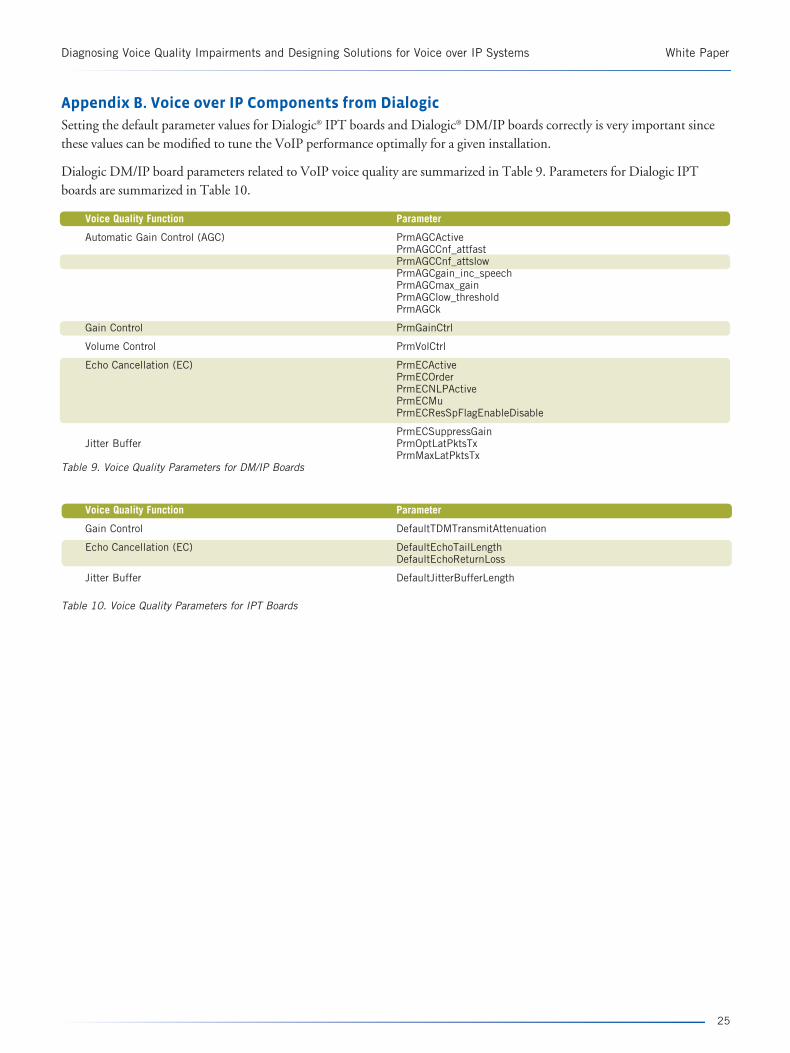
Appendix B. Voice over IP Components from Dialogic
Setting the default parameter values for Dialogic® IPT boards and Dialogic® DM/IP boards correctly is very important since these values can be modified to tune the VoIP performance optimally for a given installation.
Dialogic DM/IP board parameters related to VoIP voice quality are summarized in Table 9. Parameters for Dialogic IPT boards are summarized in Table 10.
Voice Quality Function Parameter
Automatic Gain Control (AGC) PrmAGCActive PrmAGCCnf_attfast PrmAGCCnf_attslow PrmAGCgain_inc_speech PrmAGCmax_gain PrmAGClow_threshold PrmAGCk
Gain Control PrmGainCtrl
Volume Control PrmVolCtrl
Echo Cancellation (EC) PrmECActive PrmECOrder PrmECNLPActive PrmECMu PrmECResSpFlagEnableDisable
PrmECSuppressGain Jitter Buffer PrmOptLatPktsTx PrmMaxLatPktsTx Table 9. Voice Quality Parameters for DM/IP Boards
Voice Quality Function Parameter
Gain Control DefaultTDMTransmitAttenuation
Echo Cancellation (EC) DefaultEchoTailLength DefaultEchoReturnLoss
Jitter Buffer DefaultJitterBufferLength
Table 10. Voice Quality Parameters for IPT Boards

For More Information
Detailed information about configuring Dialogic DM/IP
boards and Dialogic IPT boards can be found in manuals
and help files based on the system release in use.
The manuals that discuss the .config files for Windows® 6.0
CompactPCI system releases are: • Dialogic® DM3 Architecture for CompactPCI on
Windows Configuration Guide (05-1746)
• Dialogic® IPT Series on Windows Configuration Guide (05-1752)
The manuals that discuss the .config files for Linux 6.1
CompactPCI system releases are: • Dialogic® DM3 Architecture Products on Linux
Configuration Guide (05-1876)
• Dialogic® IPT Series on Linux Configuration Guide (05-1751)
The manual that discusses the .config files for the Windows
6.0 PCI system release is: • Dialogic® DM3 Architecture PCI Products on Windows
Configuration Guide (05-1875)
Parameters used in Dialogic’s configuration manager
(DCM) for the Windows® operating system are discussed
in the DCM Online Help for specific system releases.
Relevant Standards Documents
This appendix contains a selected list of the many standards
documents consulted during the writing of this paper.
IEEE
IEEE Std 802.3-2002 (Revision of IEEE Std 802.3, 2000
Edition). Part 3: Carrier Sense Multiple Access with Collision
Detection (CSMA/CD) Access Method and Physical Layer
Specifications
[Also IEEE Std 802 Overview and Architecture, IEEE Std
802.ID Media Access Control (MAC) Bridges, IEEE Std
802.2 Logical Link Control, and IEEE Std 802.3 CSMA/
CD Access Method and Physical Layer Specification]
ETSI
ETSI EN 300 726 v8.0.1 (2000-11). Digital Cellular
Telecommunications System (Phase 2+); Enhanced Full Fate
(EFR) Speech Transcoding; (GSM 06.60 version 8.0.1 Release
1999)
ITU-TAppendix III to ITU Recommendation G.726 and Appendix II to ITU Recommendation G.727 (05/94). General Aspects of Digital Transmission Systems. Comparison of ADPCM Algorithms
G.168 (04/97) Series G: Transmission Systems and Media, Digital Systems and Networks. International Telephone Connections and Circuits – Apparatus Associated with Long-Distance Telephone Circuits. Digital Network Echo Cancellers
G.711 General Aspects of Digital Transmission Systems. Terminal Equipments. Pulse Code Modulation (PCM) of Voice Frequencies
G.723.1 Annex A (11/96) Series G: Transmission Systems and Media. Digital Transmission Systems – Terminal Equipments – Coding of Analogue Signals by Methods Other Than PCM. Dual Rate Speech Coder for Multimedia Communications Transmitting at 5.3 and 6.3 kbit/s. Annex A: Silence Compression Scheme
G.729 Annex A (11/96) Series G: Transmission Systems and Media. Digital Transmission Systems – Terminal Equipments – Coding of Analogue Signals by Methods Other Than PCM. Coding of Speech at 8 kbit/s Using Conjugate Structure Algebraic-Code-Excited Linear-Prediction (CS-ACELP). Annex A: Reduced Complexity 8 kbit/s CS-ACELP Speech Codec
G.729 Annex B (11/96) Series G: Transmission Systems and Media. Digital Transmission Systems – Terminal Equipments – Coding of Analogue Signals by Methods Other Than PCM. Coding of Speech at 8 kbit/s Using Conjugate Structure Algebraic-Code-Excited Linear-Prediction (CS-ACELP). Annex B: A Silence Compression Scheme for G.729 Optimized for Terminals Conforming to Recommendation V.70
H.245 (09/98) Series H: Audiovisual and Multimedia Systems: Infrastructure of Audiovisual Services – Communication Procedures. Control Protocol for Multimedia Communication
Network Working Group MemosRFC 1889. RTP: A Transport Protocol for Real-Time Applications (January 1996)
RFC 1890. RTP Profile for Audio and Video Conferences with Minimal Control (January 1996)
rfc2833. RTP Payload for DTMF Digits, Telephony Tones and Telephony Signals (The Internet Society, May 2000)
White Paper Diagnosing Voice Quality Impairments and Designing Solutions for Voice over IP Systems
26

www.dialogic.com
To learn more about Dialogic® products, go to www.dialogic.comDialogic Corporation9800 Cavendish Blvd., 5th FloorMontreal, Quebec CANADA H4M 2V9
INFORMATION IN THIS DOCUMENT IS PROVIDED IN CONNECTION WITH PRODUCTS OF DIALOGIC CORPORATION OR ITS SUBSIDIARIES (“DIALOGIC”). NO LICENSE, EXPRESS OR IMPLIED, BY ESTOPPEL OR OTHERWISE, TO ANY INTELLECTUAL PROPERTY RIGHTS IS GRANTED BY THIS DOCUMENT. EXCEPT AS PROVIDED IN A SIGNED AGREEMENT BETWEEN YOU AND DIALOGIC, DIALOGIC ASSUMES NO LIABILITY WHATSOEVER, AND DIALOGIC DISCLAIMS ANY EXPRESS OR IMPLIED WARRANTY, RELATING TO SALE AND/OR USE OF DIALOGIC® PRODUCTS INCLUDING LIABILITY OR WARRANTIES RELATING TO FITNESS FOR A PARTICULAR PURPOSE, MERCHANTABILITY, OR INFRINGEMENT OF ANY INTELLECTUAL PROPERTY RIGHT OF A THIRD PARTY.
Dialogic products are not intended for use in medical, life saving, life sustaining, critical control or safety systems, or in nuclear facility applications.
Dialogic may make changes to specifications, product descriptions, and plans at any time, without notice.
Dialogic is a registered trademark of Dialogic Corporation. Dialogic’s trademarks may be used publicly only with permission from Dialogic. Such permission may only be granted by Dialogic’s legal department at 9800 Cavendish Blvd., 5th Floor, Montreal, Quebec, Canada H4M 2V9. Any authorized use of Dialogic’s trademarks will be subject to full respect of the trademark guidelines published by Dialogic from time to time and any use of Dialogic’s trademarks requires proper acknowledge-ment.
Windows is a registered trademark of Microsoft Corporation in the United States and/or other countries. Other names of actual companies and products mentioned herein are the trademarks of their respective owners. Dialogic encourages all users of its products to procure all necessary intellectual property licenses required to implement their concepts or applications, which licenses may vary from country to country.
Copyright © 2008 Dialogic Corporation All rights reserved. 04/08 8908-02