diablo canyon, units 1 and 2, attachment 2 to dcl-12-050 - nrc
TRANSCRIPT

Attachments 7-15 to the Enclosure contain Proprietary Information - Withhold Under 10 CFR 2.390
EnclosureAttachment 2
PG&E Letter DCL-1 2-050
Final Safety Analysis Report Changes forProcess Protection System Replacement
Attachments 7-15 to the Enclosure contain Proprietary InformationWhen separated from Attachments 7-15 to the Enclosure, this cover sheet is decontrolled.

DCPP UNITS 1 & 2 FSAR UPDATE
operations. The monitoring systems are described in Section 11.4. The offsiteradiological monitoring program is described in Section 11.6.
Waste handling systems are incorporated in each facility design for processing and/orretention of normal operation radioactive wastes with appropriate controls and monitors toensure that releases do not exceed the limits of 10 CFR 20. The facilities are alsodesigned with provisions to monitor radioactivity release during accidents and to preventreleases from causing exposures in excess of the guideline levels specified in10 CFR 100.
3.1.4.8 Criterion 18, 1967 - Monitoring Fuel and Waste Storage (Category B)
Monitoring and alarm instrumentation shall be provided for fuel and waste storage andhandling areas for conditions that might contribute to loss of continuity in decay heatremoval and to radiation exposures.
Discussion
The fuel and waste storage and handling areas are provided with monitoring and alarmsystems for radioactivity, and the plant vents are monitored for radioactivity during alloperations. The monitoring systems are described in Section 11.4.
The spent fuel pool cooling system is equipped with adequate instrumentation for normaloperation. Water temperatures in the pool and at the outlet of the heat exchanger areindicated locally, and high pool temperature is alarmed in the control room. The spent fuelpool cooling system is described in Section 9.1.
3.1.5 RELIABILITY AND TESTABILITY OF PROTECTION SYSTEMS
GDCs related to reliability and testing of protection systems are presented in this section.A discussion of conformance follows each criterion.
3.1.5.1 Criterion 19, 1967 - Protection Systems Reliability (Category B)
Protection systems shall be designed for high functional reliability and in-service testabilitycommensurate with the safety functions to be performed.
Discussion Insert 1
The protection systems are designed for high functional reliability and inservice te ability.Each design employs redundant logic trains and measurement and equipment di rersity.Sufficient redundancy is provided to enable individual end-to-end channel tests ith eachreactor at power without compromise of the protective function. Built-in semia omatictesters provide means to test the majority of system components very rapidly. Theprotection systems are described in Section 7.2.
3.1-13 Revision 20 'November 2011

DCPP UNITS 1 & 2 FSAR UPDATE
3.1.5.2 Criterion 20, 1967 - Protection Systems Redundancy and Independence(Category B)
Redundancy and independence designed into protection systems shall be sufficient toassure that no single failure or removal from service of any component or channel of asystem will result in loss of the protection function. The redundancy provided shall include,as a minimum, two channels of protection for each protection function to be served.Different principles shall be used where necessary to achieve true independence ofredundant instrumentation components.
Discussion
Sufficient redundancy and independence is designed into the protection systems to ensurethat no single failure nor removal from service of any component or channel of a systemwill result in loss of the protection function. The minimum redundancy is exceeded iprotection function that is active with the reactor at power. Insert 2
Functional diversity and consequential location diversity are designed int 6e systems.DCPP uses a the Westingheuse Eagle 21 Process Protection System, hich is discussedin detail in Section 7.2.
3.1.5.3 Criterion 21, 1967 - Single Failure Definition (Category B)
Multiple failures resulting from a single event shall be treated as a single failure.
Discussion
When evaluating the protection systems, the ESF, and their support systems, multiplefailures resulting from a single event are treated as a single failure. The ability of eachsystem to perform its function with a single failure is discussed in the sections describingthe individual systems. The single failure criterion is discussed further at the beginning ofSection 3.1.1.
3.1.5.4 Criterion 22, 1967 - Separation of Protection and Control InstrumentationSystems (Category B)
Protection systems shall be separated from control instrumentation systems to the extentthat failure or removal from service of any control instrumentation system component orchannel, or of those common to control instrumentation and protection circuitry, leavesintact a system satisfying all requirements for the protection channels.
Discussion
The protection systems, except the Process Protection System, comply with therequirements of IEEE-279, 1971, Criteria for Protection Systems for Nuclear Power
3.1-14 Revision 20 November 2011
DCPP UNITS 1,& 2 FSAR UPDATE Insert 3
Generating Stations, although construction permits f CPP units were issued prior toissuance of the 1971 version of the standard.Each protection system is separate and distinct from the respective control systems. Thecontrol system is dependent on the protection system in that control signals are derivedfrom protection system measurements, where applicable. These signals are transferred tothe control system by isolation amplifiers that are classified as protection systemcomponents. The adequacy of system isolation has been verified by testing or analysisunder conditions of all postulated credible faults. Isolation devices that serve to protectInstrument Class IA instrument loops have all been tested. For certain applications wherethe isolator is protecting an Instrument Class IB instrument loop, and the isolation device isa simple linear device with no complex failure modes, the analysis was used to verify theadequacy of the isolation device. The failure or removal of any single controlinstrumentation system component or channel, or of those common to the controlinstrumentation system component or channel and protection circuitry, leaves intact asystem that satisfies the requirements of the protection system. The protection systemsand control systems are discussed in Chapter 7.
3.1.5.5 Criterion 23,1967 - Protection Against Multiple Disability of ProtectionSystems (Category B)
The effects of adverse conditions to which redundant channels or protection systemsmight be exposed in common, either under normal conditions or those of an accident, shallnot result in loss of the protection function.
Discussion
Physical separation and electrical isolation of redundant channels and subsystems,functional diversity of subsystems, and safe failure modes are employed in design of thereactors as defenses against functional failure through exposure to common causativefactors. The redundant logic trains, reactor trip breakers, and ESF actuation devices arephysically separated and electrically isolated. Physically separate channel trays, conduits,and penetrations are maintained upstream from the logic elements of each train.
The protection system components have been qualified by testing under extremes of thenormal environment. In addition, components are tested and qualified according toindividual requirements for the adverse environment specific to their location that mightresult from postulated accident conditions. The protection systems are discussed inSection 7.2.
3.1.5.6 Criterion 24,1967 - Emergency Power for Protection Systems (Category B)
In the event of loss of all offsite power, sufficient alternate sources of power shall beprovided to permit the required functioning of the protection systems.
Discussion
3.1-15 Revision 20 November 2011

DCPP UNITS 1 & 2 FSAR UPDATE
The facility is supplied with normal and standby emergency power to provide for therequired functioning of the protection systems.In the event of loss of normal power, emergency ac power is supplied by six dieselgenerators, as described in Chapter 8. Only four diesels are required to supply the powerrequirements with one unit in an accident situation and to bring the other to the shutdowncondition from full power.
The instrumentation and controls portions of the protection systems are supplied initiallyfrom the station batteries and subsequently from the emergency diesel generators. Asingle failure of any one component will not prevent the required functioning of protectionsystems.
3.1.5.7 Criterion 25, 1967 - Demonstration of Functional Operability of ProtectionSystems (Category B)
Means shall be included for testing protection systems while the reactor is in operation todemonstrate that no failure or loss of redundancy has occurred.
Discussion
All reactor protection channels employed in power operation are sufficiently redundant sothat individual testing and calibration, without degradation of the protection function orviolation of the single failure criterion, can be performed with the reactors at power. Suchtesting discloses failures or reduction in redundancy that may have occurred. Removalfrom service of any single channel or component does not result in loss of minimumrequired redundancy. For example, a two-out-of-three function becomes a one-out-of-twofunction when one channel is removed. F I
S1 e 4Semiautomatic testers are built into each of the two logic trains in the reactor protectionsystem. These testers have the capability of testing the major part of the protectionsystem very rapidly while the reactor is at power. Between tests, the testers continuouslymonitor a number of internal protection system points, including the associated powersupplies and fuses. Outputs of the monitors are logically processed to provide alarms forfailures in one train and automatic reactor trip for failures in both trains. A self-testingprovision is designed into each tester. Additional details can be found in Section 7.2.
3.1.5.8 Criterion 26, 1967 - Protection Systems Fail-Safe Design (Category B)
The reactor protection systems shall be designed to fail into a safe state or into a stateestablished as tolerable on a defined basis if conditions such as disconnection of thesystem, loss of energy (e.g., electric power, instrument air), or adverse environments (e.g.,extreme heat or cold, fire, steam, or water) are experienced.
Discussion
3.1-16 Revision 20 November 2011

DCPP UNITS 1 & 2 FSAR UPDATE
The tripping action of the bistable amplifier circuitry was checked after each series oftests to insure that the seismic test input had not impaired this function.
During front-to-back testing of the circuit board, an internal power supply circuit boarddisengaged from its connector causing complete failure of the module. Restrainingclamps were installed on the circuit board and the test was repeated successfully.These clamps have since been installed on all similar modules. All recorded electricalsignals performed properly during and after the tests.
In addition, as part of the overall program to demonstrate the adequacy of the seismictest previously conducted, multiple frequency, multiple axis test (Reference 11) wereperformed on an entire typical channel, including signal conditioning circuits and thebistables, of the process instrumentation system. The results of the bistable tests showthat the electrical functions of each bistable module maintained electrical operabilityboth during and after each seismic event. In addition, no spurious bistable actionsobserved. Insert 1
Su bscquently, the EagglI 21 system replaced the Hagan protection system within the
by Westinghouse (see References 40 through 12' in accordanc~e with requirementsfromn References 43 and 44. A1 sieseii3eismicG analysis was also performed toen~sure that the Eagle 21 generic testing performned by Westinghouse encomrpasses theDCPP installed condition (see Referenc~e 45), ',,hich included the effets Of the top entr,'conduit stiffness.
3.10.2.1.4 Instrument AC Inverters
A prototype UPS and regulating transformer of the DCPP UPS system was tested asdescribed in PG&E engineering seismic file No. ES-68-1.
The UPS and regulating transformer were tested while loaded at 20 kVA; and the acoutput voltage, current and frequency were monitored during the seismic test. Thepresence of, a continuous ac output voltage both during and after the test formed thebasis for determining the functional integrity of the UPS system.
During seismic testing the static inverter maintained structural integrity and functionaloperability. No variation or loss of 120 Vac output voltage was observed during or afterthe test. Therefore, the static inverter will perform its safety related functions during andafter the postulated DCPP seismic events.
3.10.2.1.5 Pressure and Differential Pressure Transmitters (Westinghouse)
Originally the safety related pressure transmitters provided by Westinghouse for DCPPwere installed to sense the following conditions:
3.10-6 Revision 20 November 2011
DCPP UNITS 1 & 2 FSAR UPDATE
36. Seismic Qualification Test Report of Class IE RTD and ThermocoupleTemperature Sensors for Conax Corp., Report No. IPS-1 165, Rev. A,June 18,1984.
37. Rosemount Report D8400102, Qualification Report for Pressure TransmitterModel 1154, (PG&E DC 6000784-117).
38. Rosemount Report D8300040, Qualification Report for Pressure TransmittersRosemount Model 1153 Series D, (PG&E DC 6000784-7-1).
39. PG&E Seismic Calculation No. IS-35, "Seismic Qualification of RosemouTransmitters." Insert 2
40. Equin mea n+ Cl.. ml ;;t-.;n Test Daa 4 'nt 0 Ear..ac 21 DF~s Ramar.+ieR '.,~ SPmm
(E=lfnmiromcntal and Scismfic Testing'), WCAP 8687, Supplement 2 E6,,Revision 0,-M 1 98..
41. C,-, ,imnrn,•,+ (, ,-lmn',•+pn Tes.t Rep,,F, C '--nl. 21 0 O a..... DR.,,a-fen S s.tem(Enyiroenmcental and Seisnmic Testing), WCAP 8687, Supplement 2 E69B,Revision 0, -erur' 1 i990.
42. Equ ipmntsn ( Qualefi~sate Test DaReig-.4 C'sr.Ir 21 PDraesacc Drategan Syte
(EnvROenmcntal and SciSMic Testing), \ACAP 8687, Supplement 2 E69C,Revision 0 Fru, 1991 .Not used.
43. Seismic Qualification of Electrical Equipment for Nuclear Power Plants, NRCRegulatory Guide 1.100, Revision 2, June 1988.
44. Recommended Practices for Seismic Qualification of Class 1 E Equipment forNuclear Power Generating Stations, IEEE 344-1987.
45~ VIkl. Ie* G l flVV m a l tmoI o..f I aqle 21 VDli DrnIsae I •Ir V VsIIV aI I V Ua I lPe - V la
for Dnn•m -( .m ,, 'n l -÷rr- (pkrnrn.- , Gl.-,klr-. (..n,,r.. D-nAr DI.sDC I I ' P nt 4.f san
2, ,A^P 13384, Revision 0, PG&E, S+ptcmber 1992.Not used.
46. PG&E Specification 1021-J-NPG, "Specification for Furnishing and DeliveringRemote Multiplexer and Visual Annunciator Equipment Associated with the MainAnnunciator Systems for Diablo Canyon Power Plant, Units 1 and 2."
47. Trentec Test Report No. 8Q017.0, dated 11/98.
48. Altran Calculation No. 98250-C-001, Revision 0, dated May 1999.
49. PG&E Seismic Calculation No. ES-66, "Seismic Qualification of WestinghouseSupplied SSPS Cabinets."
3.10-40 Revision 20 November 2011
DCPP UNITS 1 & 2 FSAR.UPDATE
Chapter 7
CONTENTS (Continued)
Section Title PaQe
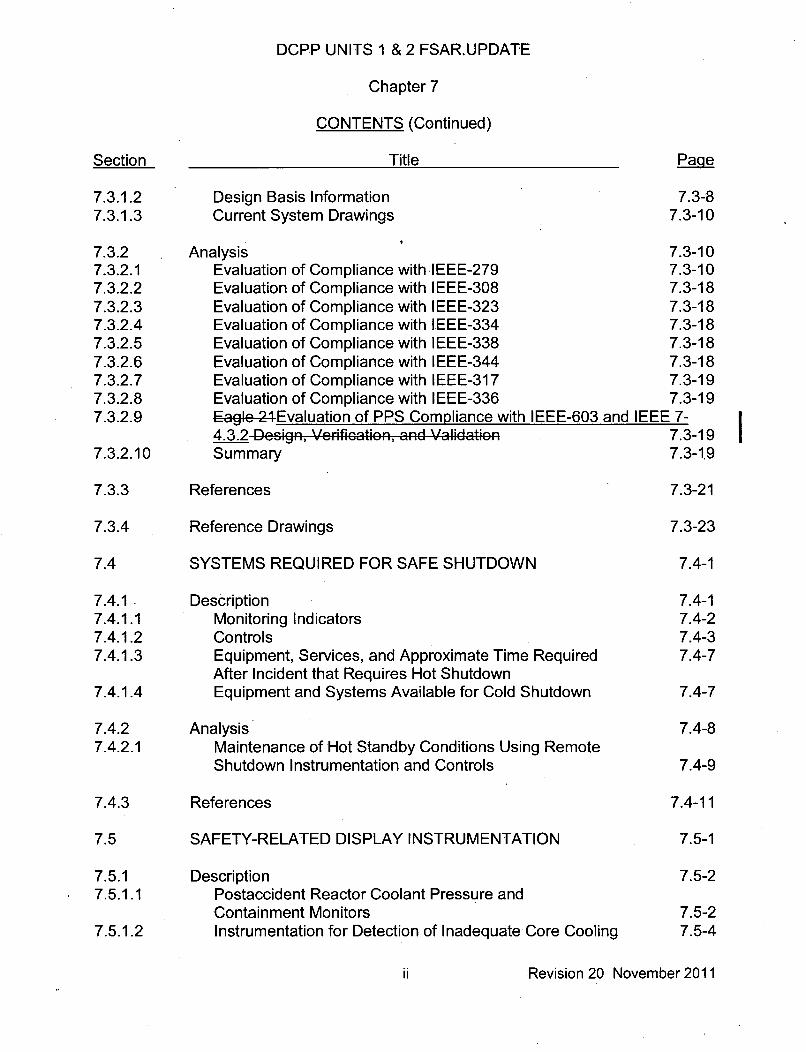
7.3.1.2 Design Basis Information 7.3-87.3.1.3 Current System Drawings 7.3-10
7.3.2 Analysis 7.3-107.3.2.1 Evaluation of Compliance with IEEE-279 7.3-107.3.2.2 Evaluation of Compliance with IEEE-308 7.3-187.3.2.3 Evaluation of Compliance with IEEE-323 7.3-187.3.2.4 Evaluation of Compliance with IEEE-334 7.3-187.3.2.5 Evaluation of Compliance with IEEE-338 7.3-187.3.2.6 Evaluation of Compliance with IEEE-344 7.3-187.3.2.7 Evaluation of Compliance with IEEE-317 7.3-197.3.2.8 Evaluation of Compliance with IEEE-336 7.3-197.3.2.9 Eag, 24Evaluation of PPS Compliance with IEEE-603 and IEEE 7-
4.3.2 Design, Verification, and Validation 7.3-197.3.2.10 Summary 7.3-1.9
7.3.3 References 7.3-21
7.3.4 Reference Drawings 7.3-23
7.4 SYSTEMS REQUIRED FOR SAFE SHUTDOWN 7.4-1
7.4.1. Description 7.4-17.4.1.1 Monitoring Indicators 7.4-27.4.1.2 Controls 7.4-37.4.1.3 Equipment, Services, and Approximate Time Required 7.4-7
After Incident that Requires Hot Shutdown7.4.1.4 Equipment and Systems Available for Cold Shutdown 7.4-7
7.4.2 Analysis 7.4-87.4.2.1 Maintenance of Hot Standby Conditions Using Remote
Shutdown Instrumentation and Controls 7.4-9
7.4.3 References 7.4-11
7.5 SAFETY-RELATED DISPLAY INSTRUMENTATION 7.5-1
7.5.1 Description 7.5-27.5.1.1 Postaccident Reactor Coolant Pressure and
Containment Monitors 7.5-27.5.1.2 Instrumentation for Detection of Inadequate Core Cooling 7.5-4
ii Revision 20 November 2011
DCPP UNITS 1 & 2 FSAR UPDATE
(17) Actuation Accuracy - Synonymous with trip accuracy, but used where theword "trip" may cause ambiguity.
(18) Indication Accuracy - The tolerance band containing the highest expectedvalue of the difference between: (a) the value of a process variable readon an indicator or recorder, and (b) the actual value of that processvariable. An indication must fall within this tolerance band. It includeschannel accuracy, accuracy of readout devices, and rack environmentaleffects but not process effects such as fluid stratification.
(19) Reproducibility - This term may be substituted for "accuracy" in the abovedefinitions for those cases where a trip value or indicated value need notbe referenced to an actual process variable value, but rather to apreviously established trip or indication value; this value is determined bytest.
7.1.1 IDENTIFICATION OF SAFETY-RELATED SYSTEMS
The instrumentation and control systems and supporting systems discussed inChapter 7 that are required to function to achieve the system responses assumed in thesafety evaluations, and those needed to shut down the plant safely are:
(1) Reactor trip system (RTS)
(2) Engineered safety features actuation system (ESFAS)
(3) Instrumentation and control power supply system
(4) Remote shutdown panel controls and instrumentation
The RTS and the ESFAS are functionally defined systems. The functional descriptionsof these systems are provided in Sections 7.2and 7.3. The trip functions identified inSection 7.2, Reactor Trip System, are provided by the following:
(1) Process instrumentation and eGntrel process protection system (PPS)(3,9,10,11)
(2) Nuclear instrumentation system(4 )
(3) Solid-state logic protection system (SSPS)(5)
(4) Reactor trip switchgear(5)
(5) Manual actuation circuitry
7.1-5Revision 15 September 2003

DCPP UNITS 1 & 2 FSAR UPDATE
The actuation functions identified in Section 7.3 are provided by the following:
(1) Process instrumentation and eentrGI-sy6tePPS( 3 ,_9 , 10, 11).
(2) SSPSolid state logic protection systcm(5)
(3) Engineered safety features (ESF) test cabinet(6 )
(4) Manual actuation circuitry
7.1.2 IDENTIFICATION OF SAFETY CRITERIA
7.1.2.1 Design Bases
The design bases and functional performance for the safety-related systems describedin this chapter are provided in Sections 7.1.2.1.1 (RTS), 7.1.2.1.2 (ESFAS), and7.1.2.1.3 (Instrumentation and Control Power Supply System).
7.1.2.1.1 Reactor Trip System
The RTS acts to limit the consequences of Condition II events (faults of moderatefrequency such as loss of feedwater flow) by, at most, a shutdown of the reactor andturbine, with the plant capable of returning to operation after corrective action. The RTSfeatures impose a limiting boundary region to plant operation that ensures that thereactor safety limits are not exceeded during Condition II events and that these eventscan be accommodated without-developing into more severe conditions.
7.1.2.1.1.1 Functional Performance Requirements
(1) Reactor Trips - The RTS automatically initiates reactor trip:
(a) Whenever necessary to prevent fuel damage for an anticipatedmalfunction (Condition II)
(b) To limit core damage for infrequent faults (Condition Ill)
(c) So that the energy generated in the core is compatible with thedesign provisions to protect the reactor coolant pressure boundaryfor limiting faults (Condition IV)
(2) Turbine Trips - The RTS initiates a turbine trip signal whenever reactor tripis initiated, to prevent the reactivity insertion that would otherwise resultfrom excessive reactor system cooldown, and to avoid unnecessaryactuation of the ESFAS.
7.1-6Revision 15 September 2003
DCPP UNITS 1 & 2 FSAR UPDATE
7.1.2.1.3.3 Quality Assurance Requirements
A description of the quality assurance program applied to safety-related instrumentationand control system equipment is in Chapter 17.
7.1.2.2 Independence of Redundant Safety-Related Systems
Separation and independence for individual channels of the RTS and ESFAS arediscussed in Sections 7.2 and 7.3, respectively. Separation of protection and controlsystems is discussed in Section 7.7. See Section 8.3 for a discussion of separation and,independence of safety-related electrical systems.For separation requirements for control board wiring, see Section 7.7.
Separation criteria for circuits entering the containment structure are met by providingseparate electrical penetrations as follows:
(1) Reactor Protection Instrumentation - Each of the Eagle-24PPS protectionsets (I, II, Ill, and IV) utilizes one or more penetrations dedicated to thatprotection set.
(2) Isolation Valves (solenoid-operated) - Each isolation valve inside thecontainment structure is connected to its respective ESF dc bus, andcircuits are run through associated 480 V bus penetrations. All isolationvalves inside the containment structure receive train A signals.Redundant isolation valves outside the containment receive train Bsignals.
(3) Isolation Valves (motor-operated) - Each isolation valve utilizes apenetration dedicated to the 480 V ESF bus that provides power to thevalve.
(4) Fan Coolers - One penetration for each fan cooler motor.
(5) Nuclear Instrumentation (out-of-core) - Four separate penetrations areprovided for out-of-core nuclear instrumentation.
The installation of other cable complies with the criteria presented in Chapter 8.
7.1.2.3 Physical Identification of Safety-Related Equipment
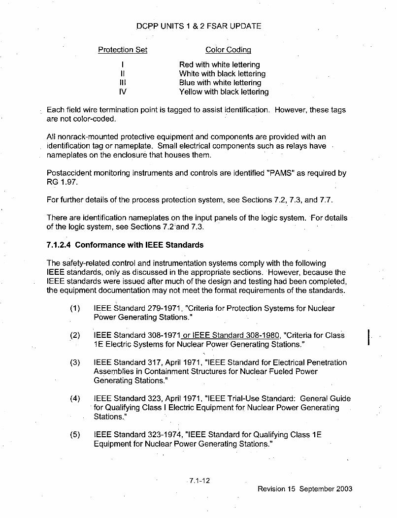
There are four separate process protection system rack sets. Separation of redundantprocess channels begins at the process sensors and is maintained in the field wiring,containment penetrations, and process protection racks to the redundant trains in theprotection logic racks. Redundant process channels are separated by locating theelectronics in different rack sets. A color-coded nameplate on each rack is used todifferentiate between different protective sets. The color coding of the nameplates is:
7.1-11Revision 15 September 2003
DCPP UNITS 1 & 2 FSAR UPDATE
Protection Set Color Coding
I Red with white letteringII White with black lettering
III Blue with white letteringIV Yellow with black lettering
Each field wire termination point is tagged to assist identification. However, these tagsare not color-coded.
All nonrack-mounted protective equipment and components are provided with anidentification tag or nameplate. Small electrical components such as relays havenameplates on the enclosure that houses them.
Postaccident monitoring instruments and controls are identified "PAMS" as required by
RG 1.97.
For further details of the process protection system, see Sections 7.2, 7.3, and 7.7.
There are identification nameplates on the input panels of the logic system. For detailsof the logic system, see Sections 7.2and 7.3.
7.1.2.4 Conformance with IEEE Standards
The safety-related control and instrumentation systems comply with the followingIEEE standards, only as discussed in the appropriate sections. However, because theIEEE standards were issued after much of the design and testing had been completed,the equipment documentation may not meet the format requirements of the standards.
(1) IEEE Standard 279-1971, "Criteria for Protection Systems for NuclearPower Generating Stations."
(2) IEEE Standard 308-1971 or IEEE Standard 308-1980, "Criteria for Class1 E Electric Systems for Nuclear Power Generating Stations."
(3) IEEE Standard 317, April 1971, "IEEE Standard for Electrical PenetrationAssemblies in Containment Structures for Nuclear Fueled PowerGenerating Stations."
(4) IEEE Standard 323, April 1971, "IEEE Trial-Use Standard: General Guidefor Qualifying Class I Electric Equipment for Nuclear Power GeneratingStations."
(5) IEEE Standard 323-1974, "IEEE Standard for Qualifying Class 1 EEquipment for Nuclear Power Generating Stations."
.7.1-12Revision 15 September 2003
DCPP UNITS 1 & 2 FSAR UPDATE
(6) IEEE Standard 334-1971, "Trial-Use Guide for Type Tests ofContinuous-Duty Class I Motors Installed Inside the Containment ofS Nuclear Power Generating Stations."
(7) IEEE Standard 336-1971, "Installation, Inspection, and TestingRequirements for Instrumentation and Electrical Equipment During theConstruction of Nuclear Power Generating Stations."
(8) IEEE Standard 338-1971, "IEEE Trial-Use Criteria for the Periodic Testingof Nuclear Power Generating Station Protection Systems."
(9) IEEE Standard 344-1971, "Trial-Use Guide for Seismic Qualification ofClass I Electric Equipment for Nuclear Power Generating Stations."
(10) IEEE Standard 344-1975, "Recommended Practices for SeismicQualification of Class 1 E Equipment for Nuclear Power GeneratingStations."
(11) IEEE Standard 603-1980 or IEEE Standard 603-1991, "IEEE Standard
Criteria for Safety Systems for Nuclear Power Generating Stations."
7.1.2.5 Conformance with Other Applicable Documents
In addition to the conformance indicated in the preceding section, the safety-relatedsystems in Chapter 7 comply with the following documents only as discussed in theappropriate sections.
(1) "Proposed General Design Criteria for Nuclear Power Plant ConstructionPermits," Federal Register, July 11, 1967.
(2) Safety Guide 6, "Independence Between Redundant Standby (Onsite)Power Sources and Between Their Distribution Systems," USAEC, March1971.
(3) Safety Guide 22, "Periodic Testing of Protection System Actuation*Functions," USAEC, February 1972.
(4) RG 1.47, "Bypassed and Inoperable Status Indication for Nuclear PowerPlant Safety Systems," USAEC, May 1973.
(5) RG 1.97, Rev. 3, "Instrumentation For Light-Water-Cooled Nuclear PowerPlants to Assess Plant and Environs Conditions During and Following anAccident," USNRC, May 1983.
7.1-13Revision 15 September 2003
DCPP UNITS 1 &2 FSAR UPDATE
(6) RG 1.152, "Criteria for Programmable Digital Computer System Softwarein Safety Related Systems in Nuclear Plants," November 1985(Regulatory Guide 1.152 endorses the guidance of ANSI/IEEE-ANS-7-4.3.2).
(7) Regulatory Guide 1.152, Revision 3, "Criteria for Use of Computers inSafety Systems of Nuclear Power Plants"
(8) RG 1.153, "Criteria for Power, Instrumentation and Control Portions ofSafety Systems," December 1985 (RG 1.153 endorses the guidance ofIEEE Standard 603-1980).
(9) ANSI/IEEE-ANS-7-4.3.2, "Application Criteria for Programmable DigitalComputer Systems in Safety Systems of Nuclear Power GeneratingStations," 1982 (ANSI/IEEE-ANS-7-4.3.2, 1982 expands and amplifies therequirements of IEEE Standard 603-1980).
(10) IEEE Standard 7-4.3.2, "Standard Criteria for Digital Computers in SafetySystems of Nuclear Power Generating Stations," 2003
7.1.3 REFERENCES
,1. IEEE Standard, 279-1971, Criteria for Protection Systems for Nuclear PowerGenerating Stations, The Institute of Electrical and Electronics Engineers, Inc.
2. Technical Specifications, Diablo Canyon Power Plant Units 1 and 2, Appendix Ato License Nos. DPR-80 and DPR-82, as amended.
3. J. A. Nay, Process Instrumentation for Westinghouse Nuclear Steam SupplySystems, WCAP-07671, April 1971.
4. J. B. Lipchak and R. A. Stokes, Nuclear Instrumentation System, WCAP-7669,April 1971.
5. D. N. Katz, Solid State Logic Protection System Description, WCAP-7672,June 1971.
6. J. T. Hailer, Engineered Safeguards Final Device or Activator Testing,WCAP-7705, February 1973.
7. IEEE Standard 308-1971, Criteria for Class 1 E Electrical Systems for NuclearPower Generating Stations, The Institute of Electrical and Electronics Engineers,Inc.
8. T. W. T. Burnett, Reactor Protection System Diversity in WestinghousePressurized Water Reactors, WCAP-7306, April 1969.
7.1-14Revision 15 September 2003

DCPP UNITS 1 & 2 FSAR UPDATE
9 L .E.I DF,-o,- ,r r'-Ft-,Eag 21 M ;t ........... =,o,' r,, D .r...s D---o4,'r;--,
SWGAP 12374, Fotmo 1989 (WPrOPrietar,' Class 2).
Insert 1
7.1-15Revision 15 September 2003

DCPP UNITS 1 & 2 FSAR UPDATE
7.2 REACTOR TRIP SYSTEM
7.2.1 DESCRIPTION
This section provides a system description and the design bases for the reactor tripsystem (RTS).
7.2.1.1 System Description
The RTS uses sensors that feed the process protection system (PPS) process circuitry -
consisting of two to four redundant channels, which monitor various plant parameters.The RTS also contains the solid state protection system (SSPS) logic circuitrynecessary to automatically open the reactor trip breakers. The logic circuitry consists oftwo redundant logic trains that receive input from the protection channels.
Each of the two trains, A and B, is capable of opening a separate and independentreactor trip breaker (52/RTA and 52/RTB). The two trip breakers in seriesconnectthree-phase ac power from the rod drive motor generator sets to the rod drive powerbus, as shown in Figure 7.2-1, Sheet 2. For reactor trip, a loss of dc voltage to theundervoltage coil releases the trip plunger and trips open the breaker. Additionally, anundervoltage trip auxiliary relay provides a trip signal to the shunt trip coil that trips openthe breaker in the unlikely event of an undervoltage coil malfunction. When either of thetrip breakers opens, power is interrupted to the rod drive power supply, and the controlrods fall by gravity into the core. The rods cannot be withdrawn until an operator resetsthe trip breakers. The trip breakers cannot be reset until the bistable, which initiated thetrip, reenergizes. Bypass breakers BYA and BYB are provided to permit testing of thetrip breakers, as discussed below.
7.2.1.1.1 Reactor Trips
The various reactor trip circuits automatically open the reactor trip breakers whenever acondition monitored by the RTS reaches a preset level. In addition to redundantchannels and trains, the design approach provides an RTS that monitors numeroussystem variables, thereby providing RTS functional diversity. The extent of this diversityhas been evaluated for a wide variety of postulated accidents and is detailed inReference 1.
Table 7.2-1 provides a list of reactor trips that are described below.
7.2.1.1.1.1 Nuclear Overpower Trips
The specific trip functions generated are:
(1) Power Range High Nuclear Power Trip - The power range high nuclearpower trip circuit trips the reactor when two of the four power rangechannels exceed the trip setpoint.
7.2-1 Revision 20 November 2011

DCPP UNITS 1 & 2 FSAR UPDATE
There are two independent bistables each with its own trip setting (a highand a, low setting). The high trip setting provides protection during normalpower operation and is always active. The low trip setting, which providesprotection during startup, can be manually blocked when two of the fourpower range channels read above approximately 10 percent power (P-10).Three of the four channels sensing below 10 percent power automaticallyreinstate the trip function. Refer to Table 7.2-2 for a listing of all protectionsystem interlocks.
(2) Intermediate Range High Neutron Flux Trip - The intermediate range highneutron flux trip circuit trips the reactor when one of the two intermediaterange channels exceeds the trip setpoint. This trip, which providesprotection during reactor startup, can be manually blocked if two of thefour power range channels are above approximately 10 percent power(P-1 0). Three of the four power range channels below this valueautomatically reinstate the intermediate range high neutron flux trip. Theintermediate range channels (including detectors) are separate from thepower range channels. The intermediate range channels can beindividually bypassed at the nuclear instrumentation racks to permitchannel testing during plant shutdown or prior to startup. This bypassaction is annunciated on the control board.
(3) Source Range High Neutron Flux Trip - The source range high neutronflux trip circuit trips the reactor when one of the two source range channelsexceeds the trip setpoint. This trip, which provides protection duringreactor startup and plant shutdown, can be manually blocked when one ofthe two intermediate range channels reads above the P-6 setpoint valueand is automatically reinstated when both intermediate range channelsdecrease below the P-6 value. This trip is also automatically bypassed bytwo-out-of-four logic from the power range interlock (P-1 0). This tripfunction can also be reinstated below P-10 by an administrative actionrequiring manual actuation of two control board-mountedswitches. Eachswitch will reinstate the trip function in one of the two pr-`teotienSSPS logictrains. The source range trip point is set between the P-6 setpoint(source range cutoff flux level) and the maximum source range flux level.The channels can be individually bypassed at the nuclear instrumentationracks to permit channel testing during plant shutdown or prior to startup.This bypass action is annunciated on the control board.
(4) Power Range High Positive Nuclear Power Rate Trip - This circuit trips thereactor when an abnormal rate of increase in nuclear power occurs in twoof the four power range channels. This trip provides protection against rodejection and rod withdrawal accidents of low worth from middle to lowpower conditions and is always active. -I
7.2-2 Revision 20 November 2011

DCPP UNITS 1 & 2 FSAR UPDATE
the turbine and steam piping from excessive moisture carryover caused by high-high
steam generator water level. Other turbine trips are discussed in Chapter 10.
The logic for this trip is shown in Figure 7.2-1, Sheets 2, 4, 10 and 16.
The analog portion of the trip shown in Figure 7.2-1, Sheet 16, is represented bydashed lines. When the turbine is tripped, turbine autostop oil pressure drops, and thepressure is sensed by three pressure sensors. A logic output is provided from eachsensor when the oil pressure drops below a preset value. These three outputs aretransmitted to two redundant two-out-of-three. logic matrices, either of which trips thereactor if above P-9.
The autostop oil pressure signal also dumps the emergency trip fluid, closing all of theturbine steam stop valves. When all stop valves are closed, a reactor trip signal isinitiated if the reactor is above P-9. This trip signal is generated by redundant (twoeach) limit switches on the stop valves.
7.2.1.1.1.7 Safety, Injection Signal Actuation Trip
A reactor trip occurs When the safety injection system (SIS) is actuated. The means ofactuating the SIS are described in Section 7.3. Figure 7.2-1, Sheet 8, shows the logic.for this trip.
7.2.1.1.1.8 Manual Trip
The manual trip consists of two switches with four outputs on each switch. Each switchprovides a trip signal for both trip breakers and both bypass breakers. (Operating amanual trip switch also removes the voltage from the undervoltage trip coil.)There are no interlocks that can block this trip. Figure 7.2-1, Sheet 3, shows themanual trip logic.
7.2.1.1.1.9 Seismic Trip
The seismic trip system operates to shut down reactor operations should groundaccelerations exceed a preset level in any two of the three orthogonal directionsmonitored (one vertical, two horizontal). The preset level is indicated in the TechnicalSpecifications (Reference 4).
Three triaxial sensors (accelerometers) are anchored to the containment base in threeseparate locations 120 degrees apart (Figure 7.2-6). Each senses acceleration in threemutually orthogonal directions. Output signals are generated when groundaccelerations exceed the preset level. These signals, lasting from 6 to 20 seconds'(adjustable), are transmitted to the Trains A and B solid state protection syst-,rn (SSPS).If two of the three sensors in any direction produce simultaneous outputs, the logicproduces trains A and B reactor trip signals. The PPS channels are designed so thatupon loss of electrical power to any channel, the output of that channel is a trip signal.The seismic trip channels are an exception to the fail-safe design. Since no credit is
7.2-10 Revision 20 November 2011

DCPP UNITS 1 & 2 FSAR UPDATE
taken in accident analyses for the seismic trip, the seismic trip channels are designedenergize-to-actuate to eliminate the possibility of spurious trips.
7.2.1.1.1.10 Automatic Trip Logic
The general alarm system, described in Reference 5, maintains a check on each train ofthe solid state logic; protection system.-SPS for the existence of certain undesirableconditions. Both trains are tripped if an abnormal condition occurs simultaneously inboth trains. Reference 5 states that SSPS printed circuit boards (PCBs) use MotorolaHigh Threshold Logic (MHTL). MHTL based PCBs are obsolete and are being replacedwith PCBs which are not based on MHTL (reference 33). The replacement universallogic, safeguards driver, or under voltage driver PCBs have diagnostic features that canactivate a general warning alarm when there is a critical board problem.
7.2.1.1.1.11 Reactor Trip Breakers
The reactor trip breakers are equipped for automatic actuation of both the undervoltagetrip device and the shunt trip device. The reactor trip breakers are also equipped topermit manual trip of the breakers at the switchgear cabinet.
7.2.1.1.2 Reactor Trip System Interlocks
7.2.1.1.2.1 Power Escalation Permissives
The overpower protection provided by the out-of-core nuclear instrumentation consistsof three discrete, but overlapping, levels. Continuation of startup operation or powerincrease requires a permissive signal from the higher range instrumentation channelsbefore the lower range level trips can be manually blocked by the operator.
A one-out-of-two intermediate range permissive signal (P-6) is required prior to sourcerange level trip blocking and detector high voltage cutoff. Source range level trips areautomatically reactivated and high voltage restored when both intermediate rangechannels are below the permissive (P-6) levels. There is a manual reset switch foradministratively reactivating the source range level trip and detector high voltage whenbetween the permissive P-6 and P-10 level, if required. Source range level trip blockand high voltage cutoff are always maintained when above the permissive P-10 level.
The intermediate range level trip and power range (low setpoint) trip'can be. blockedonly after satisfactory operation and permissive information are obtained fromtwo-out-of-four power range channels. Individual blocking switches are provided so thatthe low range power range trip and intermediate range trip can be independentlyblocked. These trips are automatically reactivated when any three of the four powerrange channels are below the permissive (P-1 0) level, thus ensuring automaticactivation to more restrictive trip protection.
7.2-11 Revision 20 November 2011

DCPP UNITS 1 & 2 FSAR UPDATE
The development of permissives P-6 and P-1 0 is shown in Figure 7.2-1, Sheet 4. All ofthe permissives are digital; they are derived from analog signals in the nuclear powerrange and intermediate range channels.
See Table 7.2-2 for:the list of protection system interlocks.7.2.1.1.2.2 Blocks of Reactor Trips at Low Power
Interlock P-7 blocks a reactor trip at low power (below approximately 10 percent of fullpower) on a low reactor coolant flow or reactor coolant pump open.breaker signal inmore than one loop, reactor coolant pump undervoltage, reactor coolant pumpunderfrequency, pressurizer low pressure, and pressurizer high water level on bothunits. See Figure 7.2-1, Sheets 5 and 6 for permissive applications. The low powersignal is derived from three-out-of-four power range neutron flux signals below thesetpoint in~coincidence with one-out-of-two turbine impulse chamber pressure signalsbelow the setpoint (low plant load). The P-8 interlock blocks a reactor trip when theplant is below a preset level specified in the Technical Specifications on a low reactorcoolant flow in any one loop. The block action (absence of the P-8 interlock signal)occurs when three-out-of-four neutron flux power range signals are below the setpoint.Thus, below the P-8 setpoint, the reactor is allowed to operate with one, inactive loop,and trip will not occur until two loops are indicating low flow. See Figure 7.2-1, Sheet 4,for derivation of P-8, and Sheet 5 for the applicable logic.The P-9 interlock blocks a reactor trip below the maximum value of 50 percent of fullpower on a turbine trip signal. See Figure 7.2-1, Sheets 2, 4, and 16 for the applicationlogic. The reactor trip on turbine trip is actuated by two-out-of-three logic fromemergency trip fluid pressure signals or by all closed signals from the turbine steamstop valves.
See Table 7.2-2 for the list of protection system blocks.
7.2.1.1.3 Coolant Temperature Sensor Arrangement and CalculationalMethodology
The individual narrow range cold and hot leg temperature signals required for input tothe reactor trip circuits and interlocks are obtained using resistance temperaturedetectors (RTDs) installed in each reactor coolant loop.
Inser1The cold leg temperature measurement on each loop is accomplished with a dualelement narrow-range RTD mounted in a thermowell. T ...........inherently redundant in that either: senSOr can adequatel.y r epresent the cold leg-,temperature measUrement. Temperature streaming in the cold leg is not a concern dueto the mixing action of the reactor coolant purnp.
Insert 2The hot leg temperature measurement on each loop is accomplished with three dualelement narrow-range RTDs mounted in thermowells spaced 120 degrees apart ar undthe circumference of the reactor coolant pipe for spatial variations. One of the,in each therm.well is an nstalled spare. I
7.2-12 Revision 20 November 2011

n CDD I IIITZ I 2Q. ) r=(ZA I~ I~lTILJ~.JI I ~
Insert 3
g RTD signals are input to thepas follows-
Thc-c cold and hot legdigital electronics and p
.narFew FaFr 9rr 4~
The t'.vo filtered co~ld leg temperaturWe inpu t si.gnals- D~sedtdetermine a group a."ragc ,alue Ttovi The 2 in.put redundant snSo. algorithm(RSA) calculates the group average value based on the number of good iptsignals.
If both input signals ar~e BAD, the group valuc is set equal to the average of the b~o badsensor values. if one signal is BAD and the o•the is DISABLED, the group value is setequal to the value of the bad sensor. The group quality is set to _BAD in ei-t~her case.
if one of the input signals isBAD and the other is GOOD, the group va'Oe is set equal tothe GOOD value. A cossecGheck is not pe~fOFred. The groupl quality is set to
if neither of the input signals is BAD, a consistency check is pe~fermed. if the deviationof these two signals is within an acceptance tolerance (±DE=LTAC), the group quality isset. t.6 GO:.(OD and the groeup value is set equal to the avrgif the MeA~ inputs. if thediffere•ne exGeeds ±DELTA,, the group quality is set to BAD, and the individual signalqualities are set to POOR. The group value is set equal to the average o~f the lAPo
DELTAC is a fixed input parameter based on operating experience. One DELTAGvalue is required for each protectfion set.
Estimates on f ht leg temuperature are derived from eah, THn . nnLAA-ifl nV-U fleUvs
Thestij -4j - P-Bjsjj (7.24)
where-
i f i-s the f*lteFed- T.I hijbocj-nflaF. for the jth RTD ' - 1 to 3) in the ith loop (i - 1 to 1
-power fraction befing used to correct the bias value being used forF any
P-, (T fv Tc\ve )/ATe, (7.2 5)
where4
ATP i the full power AT in the ith loop
7.2-13 Revision 20 November 2011

DCPP UNITS 1 & 2 FSAR UPDATE
S?-mnualy iput bias that corr~ects the ind'Aua T--Qvalue to the leep-
avcragc.
The three hot leg te.perature estimates- Th for eah toopiare processed todetermine a group average valu at-veu. The 3 input RSA calculates the group value-
Sbased on the available number of good input values.
if all three inputs are BAD, the group value as set to the average of the three inputsensor values. The group value quality is set to BAD. if only one input is GOOD, thegroup value is set equal to the value of the good sensor. The group quality is set toBAD.
If teo inputs arc good, the difference between the two sesosiscmpared to DELTAH.If the inputs do not agree withir ±DELTA.H, the group quality is set to BAD and thequality of both inputs is set to POOR. if the inputs agree, the greup quality is set toGOOD. The group value is set equal to the average of the two inputs in either ,cae.
If all three iputs a ,e good, anr average of the thee estimated hot leg temperaturfes iscomrputed and the individual signals are checked to deter•min iOf they agree within" DELTAH of the average value. If al1l of the signals agee within ± D ELTAH of theaverage value, the group quality is set to GOOD. The group valu•e,,,his set tothe-average of the three estimated average hot leg temperatures.
if the signal v'alues do not all agree within ± DELTAH of the average, the RSA will deletethe sign•l value that is furthest f.rom the average. The quality of this signal will be set to-POOR and a consistency check Will the•n be pe,1ormed On the remaining GOOD signals..if these signals pass the consistency check, the group value will be taken as theaverage of these GOOD signals and the group quality will be set to POOR. However, if.these signals again fail the consistency check (wA~ithin ± DELTAH), then the group valuewill be set to the average of these two signals; but the group quality will be set to BAD.All of the individual sIgnals will h thei quality set to POOR.
DELTAH is a fxed input paramreter based upon temrperature fluctuation within the hot
leg. One DELTAH v,,alue is required for each protect"io Set.
DELTA T and T Average are calculated as follows:
ATi=Thavei -lcave1 (7.2-4-6)
Tag =(Tave +Tfae )/2.0 Insert 4 (7.2-5-7)
The aI,-UIated values for DELTA T and Tare then utilized oro•, th the reainder Ofthe v•Detemrperature ard OveFpewer DELTA T protection hannel and channel outputsfor control purposes.
7.2-14 Revision 20 November 2011

DCPP UNITS 1 & 2 FSAR UPDATE
A similar calculation of DELTA T is P"~ormcd for and used by the steam generatorlow low level tFrP time delay (1TD) funcTtion.
Alarmns arc generated frma )rup status that is based on the quality oef Tf W 7
out of the RSA. if the quality of either group is BAD and all of thc inputs for that grouparc not offscal Ieow,~ then the group status is set to TROUBLE and RTD FAILURE. if
eithr qulity is POOR and all of its inputs are not offscale l ow', then the group status isSet. to TROUBLE. Otherp'ise, the group status is set to GOOD.
7.2.1.1.4 Pressurizer Water Level Reference Leg Arrangement
The design of the pressurizer water level instrumentation includes a slight modificationof the usual tank level arrangement using differential pressure between an upper and alower tap. The modification shown in Figure 7.2-4 consists of the use of a sealed ereference leg instead OTthme convemntonal open column OT water. •efer to IsrSection 7.2.2.3.4 for an analysis of this arrangement. Insert 5
7.2.1.1.5 Process Protection System (PPS) n
The process protection system is described in References 3, 34, 35, and 36. I
7.2.1.1.6 Solid State (Digital) Logic Protection System (SSPS)
The s•lid state logic pro.tection. syste. . -SPS takes binary inputs, (voltage/no voltage)from the PPSpr-eess and nuclear instrument channels and direct inputs correspondingto conditions (normal/abnormal) of plant parameters. The system combines thesesignals in the required logic combination and generates a trip signal.(no voltage) to the'undervoltage coils of the reactor trip circuit breakers and an undervoltage auxiliary relaywhen the necessary combination of signals occurs. The undervoltage auxiliary relaysends a trip signal (125 Vdc) to the shunt trip coils of the reactor trip breakers. Thesystem also provides annunciator, status light, and computer input signals that indicatethe condition of bistable input signals, partial- and full-trip functions, and the status of thevarious blocking, permissive, and actuation functions. In addition, the system includesmeans for semiautomatic testing of the logic circuits. A detailed description of thissystem is provided in Reference 6. Reference 6 is based on SSPS printed circuitboards (PCBs) that use Motorola High Threshold Logic (MHTL). MHTL based PCBsare obsolete and are being replaced with PCBs which are not based on MHTL(reference 33).
7.2.1.1.7 Isolation Devices
In certain applications, it is advantageous to employ control signals providedderived fromindividual protection channels through isolation devices contained in the protectionchannel, as permitted by IEEE-279 (Reference 7) and IEEE-603 (Reference 28).
In all of these cases, signals provideddeFrved from protection channels for nonprotectivefunctions are obtained through isolation devices located in the process protection racks.
II
II
T-2-15 Revision 20 November 2011

DCPP UNITS 1 & 2 FSAR UPDATE
By definition, nonprotective functions include those signals used for control, remoteprocess indication, and computer monitoring.
Isolation devices qualification type tests are described in References 8-,9, 35, 36, and5282.7.2.1.1.8 Energy Supply and Environmental Qualification Requirements
The energy supply for the reactor trip system, including the voltage and frequencyvariations, is described in Section 7.6. The environmental qualification requirements areidentified in Section 3.11.
7.2.1.1.9 Reactor Trip System Instrumentation Trip Setpoints
The functions that require trip action are identified in the Technical Specifications.
7.2.1.1.10 Seismic Design
The seismic design considerations for the RTS are discussed in Section 3.10. Thedesign meets the requirements of Criterion 2 of the General Design Criteria (GDC)(Reference 10). A discussion of the seismic testing of the RTS equipment is presentedin Section 3.10.
The monitoring circuitry, sensors and signal electronics, for several variables that provideinputs to the reactor trip system are not seismically qualified, and in some cases, are notseismically mounted or classified as Design Class I. Those circuits are:
(1) Source range (SR) nuclear instrumentation - sensors and electronics(Design Class I)
(2) Intermediate range (IR) nuclear instrumentation - sensors and electronics(Design Class I)
(3) Main turbine stop valve closed limit switches (Design Class II)
(4) Main turbine auto-stop oil pressure switches (Design Class II)
(5) 12 kV bus underfrequency relays, potential transformers and test switches(Design Class II)
(6) 12 kV bus undervoltage relays, potential transformers and test switches(Design Class II)
(7) 12 kV reactor coolant pump circuit breaker open position switches(Design Class II)
7.2-16 Revision 20 November 2011

DCPP UNITS 1 & 2 FSAR UPDATE
and breaker position switch monitoring circuits and the equipment in whichthey are mounted have been seismically analyzed to confirm that theirstructural integrity is such that no seismically induced common modefailures of the monitoring circuits or the equipment in which they aremounted exist that could degrade a primary RTS safety function.
Insert 67.2.1.2 Design Basis Information
The RTS meets IEEE criteria as set forth in IEEE-279 as described in Section 7.2.2.2.1.
The following are the generating station conditions requiring reactor trip (seeSection 7.1.2):
The fo(see F
(1) DNBR approaching the applicable limit value (see Section 4.4.1.1 andSection 4.4.2.3)
(2) Power density (kilowatts per foot) approaching rated value for Condition IIfaults (see Sections 4.2.1, 4.3.1, and 4.4.1 for fuel design limits)
(3) RCS overpressure creating stressing approaching the limits specified inSections 5.2 and 5.5
Ilowing are the variables required to be monitored in order to provide reactor tripsigure 7.2-1 and Table 7.2-1):
(1) Neutron flux
(2) Reactor coolant temperature
(3) RCS pressure (pressurizer pressure)
(4) Pressurizer water level
(5) Reactor coolant flow
(6) 'Reactor coolant pump operational status (bus voltage and frequency, andbreaker position)
(7) Steam generator water level
(8) Turbine operational status (autostop oil pressure and stop valve position)
Reactor coolant temperature is a spatially dependent variable. (See Section 7.3.1 for,discussion.)
7.2-18 Revision 20 November 2011
DCPP UNITS 1 & 2 FSAR UPDATE
demonstrated in Table 7.2-3, which lists the various trips of the RTS, the correspondingTechnical Specifications on safety limits and safety system settings, and the appropriateaccidents discussed in the safety analyses in which the trip could be utilized.
The RTS design, except the PPS, -was evaluated in detail with respect to common modefailure and is presented in References 1 and 11. The evaluation for common modefailure in the PPS is presented in Reference 37 and was approved in Reference 38. Thedesign meets the requirements of GDC 19, 22, and 23. Preoperational testing wasperformed on RTS components and systems to determine equipment readiness forstartup. This testing served as a further evaluation of the system design.
Analyses of the results of Conditions 1, 11, 111, and IV events, including considerations ofinstrumentation installed to mitigate their consequences, are presented in Chapter 15.The instrumentation installed to mitigate the consequences of load reduction and turbinetrip is identified in Section 7.4.
With the installation of the RTD bypass elimination functional upgrade as patofhtEagle 21 proccss protcction system upg.adc, the following plant operating concerns areaddressed:
(1) The possibility of loss of flow or reduced flow through the common returnline of the hot and cold RTD bypass manifold, as a result of transport timeof the temperature measurements for the RTD loop, affecting the designbasis for the overtemperature, overpower and control channels monitoringassociated with the affected RTD bypass loop is eliminated.
(2) Operator indication 6f the loop Tavg, Tavg, and Delta-T deviation alarms ismaintained, providing the operator the same detecting signals as wit Insert 7bypass loops.
(3) The potential for a failed Thot RTD affccting the loop Ta..g, Ta,•g, and ATmeasurements is reduced due to the algorithms provided in the Eagle 21......s prtcte ......... sotw r .................. .......... .... a failed RT-D
and eliminate the failed RT-Ds mneasurement from affecting these plantpaFamneteFS.
The seismic trip is provided to automatically shut down the reactor in the event of aseismic occurrence that causes the ground acceleration to exceed a preset level. Nocredit was taken for operation of the seismic trip in the safety analysis; however, itsfunctional capability at the specified trip settings is required to enhance the overallreliability of the reactor protection system.
Checks and tests of these functional units will be made as required by the TechnicalSpecifications.
7.2.2.2 Evaluation of Compliance with Applicable Codes and Standards
7.2-23 Revision 20 November 2011

DCPP UNITS 1 & 2 FSAR UPDATE
7.2.2.2.1 Evaluation of Compliance with IEEE-279
The RTSFca.-,to trip system meets the requirements of IEEE-279 as indicated below.The PPS portion of the RTS is designed to meet the later IEEE-603 (Reference 28) andIEEE Standard 7-4.3.2 (Reference 31) standards. Evaluation of the PPS compliancewith these standards is contained in Section 7.2.2.2.9.
7.2.2.2.1.1 Single Failure Criterion
The protection system is designed to provide two, three, or four instrumentation channelsfor each protective function and redundant (two) logic trains. These redundant channelsand trains are electrically isolated and physically separated. Thus, any single failurewithin a channel or train will not prevent protective action at the system level whenrequired. This meets the requirements of Criterion 20 of the GDC. The PPS channelsare designed so that upon loss of electrical power to any channel, the output of thatchannel is a trip signal (see Sections 7.2.1.1.1.4 and 7.2.1.1.1.9 for exceptions). Thismeets the requirements of GDC 26.
To prevent the occurrence of common mode failures, such additional measures asfunctional diversity, physical separation, testing, as well as administrative control duringdesign, production, installation, and operation are employed, as discussed inReference 11, for protection logic. Standard reliability engineering techniques were usedto assess the likelihood of trip failure due to random component failures. Common modefailures were also qualitatively investigated. It was concluded from the evaluation thatthe likelihood of no trip following initiation of Condition II events is extremely small(2 x 10⁻⁷ derived for random component failures). The solid-state protection systemdesign has been evaluated by the same methods as used for the relay system and thesame order of magnitude of reliability is provided.
7.2.2.2.1.2 Quality of Components and Modules
For a discussion on the quality assurance program for the components and modules usedin the RTS, refer to Chapter 17. The quality used meets the requirements of Criterion 1 ofthe GDC.
7.2.2.2.1.3 Equipment Qualification
For a discussion of the tests made to verify the performance requirements, refer toSection 3.11. The test results demonstrate that the design meets the requirements ofGDC 23.
7.2.2.2.1.4 Independence
Each individual channel is assigned to one of four channel designations, e.g.,Channel 1, 119 111, or IV. See Figure 7.2-5. Channel independence is carried throughout
7.2-24 Revision 20 November 2011

DCPP UNITS 1 & 2 FSAR UPDATE
the system, extending from the sensor through to the devices actuating the protectivefunction. Physical separation is used to achieve separation of redundant transmitters.Separation of wiring is achieved using separate wireways, cable trays, conduit runs, andcontainment penetrations for each redundant channel. 'Redundant process equipment isseparated by locating electronics in different protection rack sets. Each redundantchannel is energized from a separate ac power feed. This meets the requirements ofGDC 20.
Position Regarding Scparation of Isolatedl Signal Outputs within PrFOc C 5 PrFotection
It is PG&E's position that specific p•hysical separation is not requ•icd within the proceIs
protectien r.acks between the protection • iFruits and isoated nonprotection circuits, andthat the degree Of electrical separation plus the physical seartin sociated with theinsulatin• on the wires IS • ufficient to meet the requirem.. ents of IEEE 279.
The justification for this postio. i that IEEE 279 co.ers this situation inthreeparagraphs quoted below:
4.2 Single Failure Criterion. Any single failue within the pirtection systemrshall not prevent proper protective action at the system level whenFequ Fed-.
4.6 Chann el Independence. Channels that provide signals for the samneprotective function shall be independent and physic~ally separated toaccomplish dec~oupling of the effects of -unsafe environmental factors,electric; transients, and physical accident consequences dcumented in the
during mnaintenance operations Or in the event Of channel malfunction.
4.7.2 Isolated Dev,;ces. The transm.ission of signals fr om pro.tection systemrequipent for control system use shall be- througu l isollation devi.es, whi•h
shall be classified as pa of the protection- system and shall meet all ther-equiremnents of this, doc-umnent. No cr~edible failur~e at teotu fa
fromn Meeting the minimu performance requierements specified inthedesign base.
Examples of credible failures include shodF circuits, open circ~uits, grounds,and the application of the mnaximnum credible ac and dG potential. A failure
inanisoation devic~e is evaluated in the same manner as a failure of otherequipment in the protection system.
Theintn of 4.2 and 4.6 with regard to pr-otection signals is handled through a-combination of electrical and physical separation. The electrical separation is handledby supplying each protecation rack set with separate independent sources of power.
7.2-25 Revision 20 November 2011

DCPP UNITS 1 & 2 FSAR UPDATE
Physical separation is- proIvided by loc1ating redundant Ghannels in separIte racks sets.Thus separation, both electrical and physical, outside the rack is ensured. The intent of4.7.2 is mnet 'within the process protec~tion racks by the pro'visien of qualified isolIatorFs thathave been tested and verified to pe~fe~ properly under the credible failures listed i4.7.2. The isolator is designed to be an electrical barrier between protectionannonprotec~tion and, as- such, the degree Of physical separation provided within themoedules is- that which is cnsistent with the voltagesinovd
The question of whether or not specific physical se paration is requir~ed is best addressedby reviewing the potential haz-ards involved. There are three general categories Ofhazards that mnust be protected against. These arc mi~ssiles, oeletrical faults, and fire.Missiles extemnal to the rac~k can be ruled out on the basis that the racks are located in,general plant areas where it is not credible to assumne misie capable o~f penetrating thesteel racjk. Missiles within the rack can be ruled out on the basis that there is nomechanism. withfin the racks for the generation of miessiles with sufficient energy to causedamnage to the hardw1areo iig
Electrical fapults1 within a rack constitute a single failure. Since there isno interamechanismn capable of simultaneously causing such a failure in more than one protectionset, the result is acceptable. The plant rem~ains safe with three out of the four protectionsets remaining in operation. A few ver; specificelectrical faults external to the protectionracks on the signals derived fromn protection channels mnay have access to the outputs of-all protection set simultaneously. Ho~weverF, the isolators have been shown t rvnthese distur~bances fromn entering the pro~tectio~ncircuits; thus the results arc acceptable.
Fire external to the racks is a potential hazard; however, fire retardant paint and wiring,fire barriers at the r-ack entrances, and adequt seartion external to the racks providea satisfactOr;y defense against thee hazard. For fu~ther discussions on firFe proetection, seeSections 8.3.1 and 9A.5.. A potential cause of fire within Mmor than one protection set i-sa;;n. ectqnric.Eal fault involving the nonprotection outputs fromn these sets; however, it hasbeen verified during the isolator tests that the fault current is terminated by the failure ofGertain components with no damage occurring in the wiring leading to the module. Thus-,a fire within a rack set due to high current igiigoetherwise damaging the wiring is notpossibe.
The remaining sourc eof fire within the racks a short circouit within the protectio~n
protection sets remnain-.
it is thus esta-blished that no credible failure associated with the isolator output 'wiringviolates the single failure critekrion therefor e, the present method of rack wiring isentirFelyadequate.-
7.2-26 Revision 20 November 2011

DCPP UNITS 1 & 2 FSAR UPDATE
7.2.2.2.1.5 Separation of Multiplexed, Isolated Solid-State Protection SystemSignals
Information from both SSPS logic trains is transmitted to the plant control boards andcomputer using a multiplex system. To ensure separation of the signals from each train,each signal is passed through an optically-coupled isolator. Verification tests on theseisolators using voltages of 118 Vac and 250 Vdc are described in Reference 12.
To provide physical separation between input and output circuits in the solid-stateprotection system racks, physical barriers have been provided to separate input andoutput wire bundles. This meets the requirements of GDC 22 and 24.Independence of the SSPS logic trains is discussed in Reference 6. Two reactor tripbreakers are actuated by two separate logic matrices that interrupt power to the controlrod drive mechanisms. The breaker main contacts are connected in series with thepower supply so that opening either breaker interrupts power to all control rod drivemechanisms, permitting the rods to free-fall into the core. The design philosophy-is tomake maximum use of a wide variety of measurements. The protection systemcontinuously monitors numerous diverse system variables. The extent of this diversityhas been evaluated for a wide variety of postulated accidents and is discussed inReference 1. Generally, two or more diverse protection functions would terminate theaccident conditions before intolerable consequences could occur. This meets therequirements of Criteria 21 and 23 of the GDC.
.7.2.2.2.1.6 Control and Protection System Interaction
The protection system is designed to be independent of the control system. In certainapplications, the control signals and other nonprotective functions are derived fromindividual protective channels through isolation devices. The isolation devices areclassified as part of the protection system and are located in the process protectionracks. Nonprotective functions include those signals used for control, remote processindication, and computer monitoring. The isolation devices are designed so that a shortcircuit, open circuit; or the application of 118 Vac or 140 Vdc on the isolated outputportion of the circuit (i.e., the nonprotective side of the circuit) will not affect the input(protective) side of the circuit. The signals obtained through the isolation devices arenever returned to the protective racks. This meets the requirements of Criterion 22 ofthe GDC.
A detailed discussion of the design and testing of the isolation devices is provided inReferences 8-,9, 35, 36, and 52.32. These reports include the results of applying variousmalfunction conditions on the output portion of the isolation devices. The results showthat no significant disturbance to the isolation devices input signal occurred. This meetsthe requirements of Criterion 31 of the GDC.
To provide additional assurance that the electrical wiring to and from the SSPS isolators,as installed, would not permit control-side faults to enter the protection system throughinput-output electrical coupling, tests were conducted at Diablo Canyon using voltages of
7.2-27 Revision 20 November 2011

DCPP UNITS 1 & 2 FSAR UPDATE
118 Vac, 250 Vdc, 460 Vac, 580 Vac and electrical noise. A description of these tests isprovided in References 8-,12, .and -32.
Where failure of a protection system component can cause a process excursion thatrequires protective action, the protection system can withstand another independentfailure without loss of protective action. This is normally achieved by means oftwo-out-of-four (2/4) trip logic for each of the protective functions except steam generatorprotection. The steam generator low-low water level protective function relies upontwo-out-of-three (2/3) trip logic and a control system median signal selector (MSS). Theuse of a control system MSS prevents-any protection system failure from causing acontrol system reaction resulting in a need for subsequent protective action. For detailsrefer to Reference 27.
7.2.2.2.1.7 Capability for Testing
The RTS is capable of being tested during power operation. Where only parts of thesystem are tested at any one time, the testing sequence provides the necessary overlapbetween the parts to ensure complete system operation. The process p•Ote.t.O.PPSequipment is designed to permit any channel to be maintained in a bypassed conditionand, when required, tested during power operation without initiating a protective action atthe system level. This is accomplished without lifting electrical leads or installingtemporary jumpers.
If a protection channel has been bypassed for any purpose, a signal is provided to allowthis condition to be continuously indicated in the control room.
The operability of the process sensors is ascertained by comparison with redundantchannels monitoring the same process variables or those with a fixed known relationshipto the parameter being checked. The in-containment process sensors can be calibratedduring plant shutdown, if required.
Surveillance testing of the preess pr3otection• ,,,mPPS is performed with the use of amaintenance workstation t(M/\^a•Ma.n Ma.ehi,,- Int÷er,.a "AA• 1 ,1) .1 . s...÷• The
MWSMMI is used to enter instructions to the installed test processor in the prc)ess-preteetienPPS rack being tested which then generates the appropriate test signals toverify proper channel operation. The capability is provided to test in either partial tripmode or bypass mode where the channel comparators are maintained in the not-trippedstate during the testing. Testing in bypass is allowed by the plant TechnicalSpecifications. The bypass condition is continuously indicated in the control room via anannunciator.
The power range channels of the nuclear instrumentation system are tested bysuperimposing a test signal on the actual detector signal being received by the channelat the time of testing. The output of the bistable is not placed in a tripped condition priorto testing. Also, because the power range channel logic is two-out-of-four, bypass of this
7.2-28 Revision 20 November 2011

DCPP UNITS 1 & 2 FSAR UPDATE
reactor trip function is not required. Note, however, that the source andintermediate-range high neutron flux trips must be bypassed during testing.
To test a power range channel, a TEST-OPERATE switch is provided to requiredeliberate operator action. Operation of the switch initiates the CHANNEL TESTannunciator in the control room. Bistable operation is tested by increasing the test signallevel up to its trip setpoint and verifying bistable relay operation by control boardannunciator and trip status lights.
It should be noted that a valid trip signal would cause the channel under test to trip at alower actual reactor power level. A reactor trip would occur when a second bistabletrips. No provision has been made in the channel test circuit for reducing the channelsignal level below that signal being received from the nuclear instrumentation systemdetector. A nuclear instrumentation system channel that causes a reactor trip throughone-out-of-two protection logic (source or intermediate range) is provided with a bypassfunction, which prevents the initiation of a reactor trip from that particular channel duringthe short period that it is undergoing testing. These bypasses initiate an alarm in thecontrol room.
For a detailed description of the nuclear instrumentation system, see Reference 2.
The SSPS logic trains of the RTS are designed to be capable of complete testing atpower, except for those trips listed in Section 7.2.3.2. Annunciation is provided in thecontrol room to indicate when a train is in test, when a reactor trip is bypassed, and whena reactor trip breaker is bypassed. Details of the SSPS IgiG system testing are providedin Reference 6.
The reactor coolant pump breakers cannot be tripped at power without causing a plantupset by loss of power to a coolant pump. However, the reactor coolant pump breakertrip logic and continuity through the shunt trip coil can be tested at power. Manual tripcannot be tested at power without causing a reactor trip, because operation of eithermanual trip switch actuates both trains A and B. Note, however, that manual trip couldalso be initiated from outside the control room by manually tripping one of the reactor tripbreakers. Initiating safety injection cannot be done at power without upsetting normalplant operation. However, the logic for these trips is testable at power.
Testing of the SSPS logic trains of the RTS includes a check of the input relays and alogic matrix check. The following sequence is used to test the system:
(1) Check of Input Relays - During testing of the process instrumentationsystem and nuclear instrumentation system comparators, each channelcomparator is placed in a trip mode causing one input relay in train A andone in train B to de-energize. A contact of each relay is connected to auniversal logic printed circuit card. This card performs both the reactor tripand monitoring functions. The contact that creates the reactor trip alsocauses a status lamp and an annunciator on the control board to operate.
7.2-29 ,Revision 20 November 2011

DCPP UNITS 1 & 2 FSAR UPDATE
Either train A or B input relay operation lights the status lamp and soundsthe annunciator.
Each train contains a multiplexing test switch. This switch is normallyconfigured such that train A is in the A+B position, while train B is in theNormal position. Administrative controls are used to control thisconfiguration and may be changed to other configurations as necessary tomeet plant conditions. The A+B position alternately allows information tobe transmitted from the two trains to the control board. A steady-statuslamp and annunciator indicates that input relays in both trains have beendeenergized. A flashing lamp means that both input relays in the two trainsdid not deenergize. Contact inputs to the logic protection system, such asreactor coolant pump bus underfrequency relays, operate input relays thatare tested by operating the remote contacts as previously described andusing the same indications as those provided for bistable input relays.
Actuation of the input relays provides the overlap between the testing ofthe SSPSl.g.ic protection system and the testing of those systemssupplying the inputs to the SSPSlog3ic protcction system. Test indicationsare status lamps and annunciators on the control board. Inputs to theSSPSlogic protection system are checked one channel at a time, leavingthe other channels in service. For example, a function that trips the reactorwhen two-out-of-four channels trip becomes a one-out-of-three trip whenone channel is placed in the trip mode. Both trains of the SSPSlegie-protection system remain in service during this portion of the test.
(2) Check of Logic Matrices - Logic matrices are checked one train at a time.Input relays are not operated during this portion of the test. Reactor tripsfrom the train being tested are inhibited with the use of the input errorinhibit switch on the semiautomatic test panel in the train. Details ofsemiautomatic tester operation are provided in Reference 6. At thecompletion of the logic matrix tests, one bistable in each channel ofprocess instrumentation or nuclear instrumentation is tripped or is verifiedin the tripped state-to check closure of the input error inhibit switchcontacts.
With the exception of the P-8 blocking function, the logic test scheme usespulse techniques to check the coincidence logic. All possible trip andnontrip combinations are checked. Pulses from the tester are applied tothe inputs of the universal logic card at the same points electrically thatconnect to the input relay contacts. Thus, there is an overlap between theinput relay check and the logic matrix check. Pulses are fed back from thereactor trip breaker undervoltage coil to the tester. The pulses are of suchshort duration that the reactor trip breaker undervoltage coil armatureshould not respond mechanically.
7.2-30 Revision 20 November 2011

DCPP UNITS 1 & 2 FSAR UPDATE
Because the P-8 block of the one of four RCS low flow trip is not connectedto the semiautomatic tester, it is tested using the manual input functionpushbuttons. The P-8 block function is verified using only one loop of RCSlow flow on a staggered monthly frequency and all loops on a refuelingfrequency.
Test indications that are provided are an annunciator in the control roomindicating that reactor trips from the train have been blocked and that thetrain is being tested, and green and red lamps on the semiautomatic testerto indicate a good or bad logic matrix test. Protection capability providedduring this portion of the test is from the train not being tested.
The general design features and details of the testability of the SSPSIegio- Isystem are described in Reference 6. The testing capability meets therequirements of Criteria 19 and 25 of the GDC.
(3) Testing of Reactor Trip Breakers - Normally, reactor trip breakers 52/RTAand 52/RTB are in service, and bypass breakers 52/BYA and 52/BYB arewithdrawn (out of service). In testing the protection logic, pulse techniquesare used to avoid tripping the reactor trip breakers, thereby eliminating theneed to bypass them during the testing, although the associated bypassbreaker is closed to preclude an inadvertent reactor trip and to allowreactor trip breaker testing. The following procedure describes the methodused for testing the trip breakers:
(a) Bypass breaker 52/BYB is racked to test position and closed
(b) With bypass breaker 52/BYA racked out (test position), manuallyclose and trip it to verify its operation
(c) Rack in and close 52/BYA (bypasses 52/RTA)
(d) While blocking 52/RTA shunt trip, manually trip 52/RTA and 52/BYBthrough ,a protection system logic matrix
(e) Reset 52/RTA
(f) Manually trip 52/RTA using the shunt trip coil only with the shunt trip
test push button
(g) Reset 52/RTA
(h) Rack out 52/BYB
(i) Trip and rack out 52/BYA
7.2-31 Revision 20 November 2011
DCPP UNITS 1 & 2 FSAR UPDATE
(j) Repeat above steps to test trip breaker 52/RTB and bypass breaker52/BYA using bypass breaker 52/BYB to bypass 52/RTB
Auxiliary contacts of the bypass breakers are connected so that if eithertrain is placed in test while the bypass breaker of the other train is fullyracked in and closed, both reactor trip breakers and the bypass breakerautomatically trip.
Auxiliary contacts of the bypass breakers are also connected in such a waythat if an attempt is made to fully rack in and close the bypass breaker inone train while the bypass breaker of the other train is already fully rackedin and closed, both bypass breakers automatically trip. Additionally, tripsignals will be sent to both reactor trip and bypass breakers through thep-,tc-tio-n syst.. SSPS logic.
The train A and train B alarm systems operate an annunciator in the controlroom. The two bypass breakers also operate an annunciator in the controlroom. Bypassing of a protection train with either the bypass or the testswitches results in audible and visual indications.
The complete RTS is normally required to be in service. However, topermit on-line testing of the various protection channels or to permitcontinued operation in the event of a subsystem instrumentation channelfailure, a Technical Specification defining the minimum number of operablechannels and the minimum degree of channel redundancy has beenformulated. This Technical Specification also defines the requiredrestriction to operation in the event that the channel operability and degreeof redundancy requirements cannot be met.
The RTS is designed in such a way that some components' response timetests-can only be performed during shutdown. However, the safetyanalyses utilize conservative numbers for trip channel response times.The measured channel response times are compared with those used inthe safety evaluations. On the basis of startup tests conducted on severalplants, the actual response times measured are less than the times used inthe safety analyses.
(4) Bypasses - The Eagle 21 pro.ess protc.tion system PPS is designed topermit an inoperable channel to be placed in a bypass condition for thepurpose of troubleshooting or periodic test of a redundant channel. Use ofthe bypass mode disables the individual channel comparator trip circuitrythat forces the associated logic input relays to remain in the non-trippedstate until the "bypass" is removed. If the prcess protectioenPPS channelhas been bypassed for any purpose, a signal is provided to allow thiscondition to be continuously indicated in the control room. During suchoperation, the process pr.tection sysmPPS continues to satisfy the
7.2-32 Revision 20 November 2011

DCPP UNITS 1 & 2 FSAR UPDATE
single failure criterion. This is acceptable since there are 4 channels andthe two-out-of-four trip logic reduces to two-out-of-three during the test.For functions that use two-out-of-three logic, it is implicitly accepted thatthe single failure criterion is met because of the results of the systemreliability study. From the results of this it was concluded that the Eagle-21-digital PPS system availability is equivalent to the originalrespeGtove analogprocess PPSprotctin ssrev, . availability even without the incorporation ofthe redundancy, automatic surveillance testing, self calibration and selfdiagnostic features of the Eagle-24-diital PPp....... prtc-o . tm..,
EXCEPTIONS:
(a) "One-out-of-two" functions are permitted to violate the single failurecriterion during channel bypass provided that acceptable reliability ofoperation can be otherwise demonstrated and bypass time intervalis short.
(b) Containment spray actuation channels are tested by bypassing ornegating the channel under test. This is acceptable since there are4 channels and the two-out-of-four trip logic reduces to two-out-of-three during the test.
INTERLOCK CIRCUITS
A listing of the operating bypasses is included in Table 7.2-2. Thesebypasses meet the intent of the requirements of Paragraph 4.12 ofIEEE-279.
Where operating requirements necessitate automatic or manual bypass* ofa protective function, the design is such that the bypass is removedautomatically whenever permissive conditions are not met. Devices usedto achieve automatic removal of the bypass of a protective function areconsidered part of the protective system and are designed in accordancewith the criteria of this section. Indication is provided in the control room ifsome part of the system has been administratively bypassed or taken outof service. -.
*Note: The term "bypass" is defined as the meeting of the coincident
permissive (interlock) logic to permit the protective logic to becomeenabled/disabled as required. The term "bypass," in this section isnot intended to be defined as the disabling of the individualchannel comparator trip circuitry during routine test or surveillancethat forces the associated logic input relays to remain in the non-tripped state until the "bypass" is removed.
7.2-33 Revision 20 November 2011
DCPP UNITS 1 & 2 FSAR UPDATE
(5) Multiple Setpoints - For monitoring neutron flux, multiple setpoints areused. When a more restrictive trip setting becomes necessary to provideadequate protection for a particular mode of operation or set of operatingconditions, the protective system circuits are designed to provide positivemeans or administrative control to ensure that the more restrictive tripsetpoint is used. The devices used to prevent improper use of lessrestrictive trip settings are considered part of the protective system and aredesigned in accordance with the criteria of this section.
(6) Completion of Protective Action - The RTS is so designed that, onceinitiated, a protective action goes to completion. Return to normaloperation requires action by the operator.
(7) Manual Initiation - Switches are provided on the control board for manualinitiation of protective action. Failure in the automatic system does notprevent the manual actuation of the protective functions. Manual actuationrelies on the operation of a minimum of equipment. Additionally, thereactor trip and bypass breakers can be operated locally.
(8) Access - The design provides for administrative control of access to allsetpoint adjustments, module calibration adjustments, test points, and themeans for bypassing channels or protective functions. For details refer toRgeenoe 23.
(9) Information Readout - The RTS provides the operator with completeinformation pertinent to system status and safety. All transmitted signals(flow, pressure, temperature, etc.) that cause a reactor trip are eitherindicated or recorded for every channel including all neutron flux powerrange currents (top detector, bottom detector, algebraic difference, andaverage of bottom and top detector currents).
Any reactor trip actuates an annunciator.
Annunciators are also used to alert the operator of deviations from normaloperating conditions so that he may take appropriate corrective action to.avoid a reactor trip. Actuation of any rod stop or trip of any reactor tripchannel actuates an annunciator.
(10) Identification - The identification described in Section 7.1.2.3 providesimmediate and unambiguous identification of the protection equipment.
7.2.2.2.2 Evaluation of Compliance with IEEE-308 (Reference 13)
See Section 7.6 and Chapter 8 for a discussion on the power supply for the RTS andcompliance with IEEE-308 (Reference 13).
7.2.2.2.3 Evaluation of Compliance with IEEE-323
7.2-34 Revision 20 November 2011
DCPP UNITS 1 & 2 FSAR UPDATE
Refer to Section 3.11 for a discussion on Class I electrical equipment environmentalqualification and compliance to IEEE-323 (Reference 14). Documentation of theEnvironmental and Seismic qualification of the RTSproccess protection .ystem isprovided in References 2-3-,24, 25, and 26, and for the PPS in References 35, 36, and39.
7.2.2.2.4 Evaluation of Compliance with IEEE-334
There are no Class I motors in the RTS; therefore, IEEE-334 (Reference 15) does notapply.
7.2.2.2.5 Evaluation of Compliance with IEEE-338
The periodic testing of the RTS conforms to the requirements of IEEE-338(Reference 16), with the exception that ol..wing comments.
(-1-)the periodic test frequency is in accordance with spesified-in-the TechnicalSpecifications Section 5.5.18 Surveillance Frequency Control Proctramwas-conserwativcly selected, using the considerations discussed in paragraph4.3 of Rcfcrence 16, to ensure that equipment associated with protectionfunctions has not drifted beyond- its minimum performance requirements.
The test interval discussed in Paragraph 5.2 of Reference 16 is developedpriarily On past operating experience and modified, if necessary, to ensure that
system and su~bsystem protection is reibypoied. Anal'Aic mnethodsfodetermining reliability arf not used to determ;i .. ne test iral
7.2.2.2.6 Evaluation of Compliance with IEEE-344
The seismic testing, as discussed in Section 3.10, conforms to IEEE-344 (Reference 17)except the format of the documentation may not meet the'requirements because testingwas completed prior to issuance of the standard. Documentation of the Environmentaland Seismic qualification of the PPSprccss p-rtetion4" .. e-m is provided in References2-3-,35, 36, and 3921, 25-,and-26.
7.2.2.2.7 Evaluation of Compliance with IEEE-317
The electrical penetrations are designed and built in accordance with IEEE-317(Reference 18) with the following exceptions:
(1) Prototype tests were not made with all of the physical conditions of theaccident environment applied simultaneously with the electrical tests,although they were successfully made separately. For example, themomentary current tests on power penetrations are not run undersimulated accident conditions. It is felt that such tests need not be made
7.2-35 Revision 20 November 2011

DCPP UNITS 1 & 2 FSAR UPDATE
simultaneously because the construction of the penetration assemblies issuch that the outer seal is located about 4-1/2 feet away from the innerseal and the containment liner and, therefore, will not be exposed toaccident environmental conditions. The integrity of the containment is,therefore, maintained at the penetration assemblies during a loss-of-coolant accident (LOCA).
(2) Dielectric strength tests were conducted in accordance with the NationalElectrical Manufacturers Association (NEMA) standard that permits testingof this type of equipment at 20 percent higher than twice-rated voltage plus1000 V for 1 second.
(3) Wire and cable splice samples used at the containment penetrations weretested under conditions simulating a LOCA environment. Refer toSection 3.11 for a discussion on Class I electrical equipment environmentalqualification.
7.2.2.2.8 Evaluation of Compliance with IEEE-336
Diablo Canyon is in conformance with IEEE-336 (Reference 19), with the followingexceptions:
(1) Paragraph 2.4
(2) Paragraph 3(4)
"Data sheets shall contain an evaluation ofacceptability." The evaluation of acceptability isindicated on the results and data sheets by theapproval signature.
"Visual examination of contact corrosion." No visualexamination for contact corrosion is made on breakerand starter contacts unless there is evidence of waterdamage or condensation. Contact resistance testsare made on breakers rated at 4 kV and above. Nocontact resistance test is made of lower voltagebreakers or starters. Q
(3) Paragraph 6.2.2 - "Demonstrate freedom from unwanted noise." Nosystem test incorporates a noise measurement. If thesystem under test meets the test criteria, then nonot a problem. Insert8
7.2.2.2.9 Evaluation of PPS Compliance with IEEE-603 and IEEE 7-4.3.2-IDesign, m• ;r•m•m ton and mid vPmlam.IVYn
Plan arc IFEEE Standard 603 1980 (Refercencc 28), Rcgulatery Guide 1.152 I ,
7.2-36 Revision 20 November 2011
DCPP UNITS 1 & 2 FSAR UPDATE
(Reforence 20), Regulatory' Guide 1.153 (Rcfcrcnce 30), and ANSI/EEE ,ANS 7 4.3.2(RefeFen~e 31).
7.2.2.2.10 Evaluation of Compliance with AEC General Design Criteria
The RTS meets the requirements of the GDC wherever appropriate. Specific cases arenoted in this chapter.
7.2.2.3 Specific Control and Protection Interactions
7.2.2.3.1 Nuclear Power
Four power range nuclear power channels are provided for overpower protection. Anadditional control input signal is derived by auctioneering of the four channels forautomatic rod control. If any channel fails producing a low output, that channel isincapable of proper overpower protection but does not cause control rod movementbecause of the auctioneer. Two-out-of-four overpower trip logic ensures an overpowertrip, if needed, even with an independent failure in another channel.
In addition, a deviation signal gives an alarm if any nuclear power channel deviatessignificantly from any of the other channels. Also, the control system responds only torapid changes in nuclear power; slow changes or drifts are compensated by thetemperature control signals. Finally, an overpower signal from any nuclear power rangechannel will block manual and automatic rod withdrawal. The setpoint for this rod stop isbelow the reactor trip setpoint.
7.2.2.3.2 Coolant Temperature
The accuracy of the RTD temperature measurements is demonstrated during plantstartup tests by comparing temperature measurements from all RTDs with one another.The comparisons are done with the RCS in an isothermal condition. The linearity of theAT measurements obtained from the hot leg and cold leg RTDs as a function of plantpower is also checked during plant startup tests.
The absolute value of AT versus plant power is not important as far as reactor protectionis concerned. Reactor trip system setpoints are based on percentages of the indicatedAT at nominal full power, rather than on absolute values of AT. For this reason, thelinearity of the AT signals as a function of power is of importance rather than the absolutevalues of the AT. As part of the plant startup tests, the loop RTDs signals are comparedwith the core exit thermocouple signals. Note also that reactor control is based onsignals derived from protection system channels after isolation by isolation devices sothat no feedback effect can perturb the protection channels.
Because control is based on the average temperature of the loop having the highestaverage temperature, the control rods are always moved based on the mostconservative temperature measurement with respect to margins to DNB. A spurious low
.7.2-37 -Revision 20 November 2011

DCPP UNITS 1 & 2 FSAR UPDATE
Periodic surveillance of the RTS is performed to ensure proper protective action. Thissurveillance consists of checks, calibrations, and functional testing that are summarizedin the following sections.
7.2.3.1.1 Channel Checksf
A channel check consists of a qualitative assessment of channel behavior duringoperation by observation. This determination shall include, where possible, comparisonof the channel indication and/or status with other indications and/or status derived fromindependent instrument channels measuring the same parameters.7.2.3.1.2 Channel Calibration
A channel calibration shall be the adjustment, as necessary, of the channel such that itresponds within the required range and accuracy to known values of input. The channelcalibration shall encompass the entire channel including the sensors and alarm, interlockand/or trip functions, and may be performed by any series of sequential, overlapping, ortotal channel steps such that the entire channel is calibrated.
7.2.3.1.3 Actuation Logic Test
An actuation logic test shall be the application of various simulated input combinations inconjunction with each possible interlock logic state and verification of the required logicoutput. The actuation logic test shall include a continuity check, as a minimum, of outputdevices.
7.2.3.1.4 Process Protection System Channel Operational Test
A channel operational test shall be the injection of a simulated signal into the channel asclose to the sensor as practicable to verify operability of alarm, interlock, and/or tripfunctions. The channel operational test shall include adjustments, as necessary, of thealarm, interlock, and/or trip setpoints such that the setpoints are within the requiredrange and accuracy.
7.2.3.1.5 Trip Actuating Device Operational Test
A trip actuating device operational test shall consist of operating the trip actuating deviceand verifying operability of alarm, interlock, and/or trip functions. The trip actuatingdevice operational test shall include adjustment, as necessary, of the trip actuatingdevice such that it actuates at the required setpoint within the, required accuracy.
7.2.3.1.6 Reactor Trip System Response Time
The RTS response time shall be the time interval from when the monitored parameterexceeds its trip setpoint at the channel sensor until loss of stationary gripper coil voltage.
7.2.3.2 Compliance with Safety Guide 22
7.2-42 Revision 20 November 2011

DCPP UNITS 1 & 2 FSAR UPDATE
Periodic testing of the RTS actuation functions, as described, complies with AEC SafetyGuide 22 (Reference 22). Under the present design, there are protection functions thatare not tested at power. These are:
(1) Generation of a reactor trip by tripping the reactor coolant pump breakers
(2) Generation of a reactor trip by tripping the turbine
(3) Generation of a reactor trip by use of the manual trip switch
(4) Generation of a reactor trip by actuating the safety injection system
(5) Generation of a reactor trip by general warning circuitry (both redundanttrains)
(6) Generation of a reactor trip by closing both reactor trip bypass breakers
The actuation logic for the functions listed is tested as described in Section 7.2.2. Asrequired by Safety Guide 22, where equipment is not tested during reactor operation, ithas been determined that:
(1) There is no practicable system design that would permit operation of theequipment without adversely affecting the safety or operability of the plant.
(2) The probability that the protection system will fail to initiate the operation ofthe equipment is, and can be maintained, acceptably low without testingthe equipment during reactor operation.
(3) The equipment can be routinely tested when the reactor is shut down.
Where the ability-of a system to respond to a bona fide accident signal is intentionallybypassed for the purpose of performing a test during reactor operation, each bypasscondition is automatically indicated to the reactor operator in the main control room by aseparate annunciator for the SSPS train in test. Test circuitry does not allow two SSPStrains to be tested at the same time so that extension of the bypass condition toredundant systems is prevented.
7.2.4 REFERENCES
1. T. W. T. Burnett, Reactor Protection System Diversity in Westing-housePressurized Water Reactors, WCAP-7306, April 1969.
2. J. B. Lipchak, and R.A. Stokes, Nuclear Instrumentation System, WCAP-7669,April 1971.
7.2-43 Revision 20 November 2011
DCPP UNITS 1 & 2 FSAR UPDATE
3. J. A. Nay, Process Instrumentation for Westinghouse Nuclear Steam SupplySystems, WCAP-7671, April 1971.
4. Technical Specifications, Diablo Canyon, Power Plant Units 1 and 2, Appendix Ato License Nos. DPR-80 and DPR-82, as amended.
5. D. N. Katz, Solid State Logic Protection System Description, WCAP-7488L,January 1971.
6. D. N. Katz, Solid State Logic Protection System Description, WCAP-7672, InSE
June 1971.7. IEEE Standard 279-1971, Criteria for Protection Systems for Nucle ower
Generating Stations, The Institute of Electrical and Electronics ineers.
8. j. P. [ole Ni~e a ult Su.mI* e, arnd "ma d-,A FCran.~g Test~ Inaiaaaal po
fo r WeAtaoCnqha. pe Eagl 2ci )1 D rOant no Dreter-atmioInr Upgrjad "'CA ,.7a33,
June 1988 (W Proprietary Class 2).
9. R. Bartholomew and J. Li pchak, Test Report, Nuclear Instrumentation -SystemIsolation Amplifier, WCAP-7819, Rev. 1, January 1972.
10. Proposed General Design Criteria for Nuclear Power Plant Construction Permits,Federal Register, July 11, 1967.
11. W. C. Gang 10ff, An Evaluation of Anticipated Operational Transients inWestinghouse Pressurized Water Reactors, WCAP-7486, May 1971.
12. D. N. Katz, et al., Westinghouse Protection Systems Noise Tests, WCAP-1 2358,Revision 2, October 1975 (W Proprietary Class 3).
13. IEEE Standard 308-1971, Criteria for Class 1 E Electric Systems for NuclearPower Generating Stations, The Institute of Electrical and ElectronicsEngineers, Inc.
14. IEEE Standard 323-1971, Trial-Use Standard: General Guide for QualifyingClass I Electric Equipment for Nuclear Power Generating Stations, The Institute ofElectrical and Electronics Engineers, Inc.
15. IEEE Standard 334-1971, Trial-Use Guide for Type Tests of Continuous-DutyClass I Motors Installed Inside the Containment of Nuclear Power GeneratingStations, The Institute of Electrical and Electronics Engineers, Inc.
16. IEEE Standard 338-1971, Trial-Use Criteria for the Periodic Testing- of NuclearPower Generating Station Protection Systems, The Institute of Electrical andElectronics Engineers Inc.
I
7.2-44 Revision 20 November 2011

DCPP UNITS 1 & 2 FSAR UPDATE
17. IEEE Standard 344-1971, Trial-Use Guide for Seismic Qualification of Class IElectric Equipment for Nuclear Power Generating Stations, The Institute ofElectrical and Electronics Engineers, Inc.
18. IEEE Standard 317-1971, Electric Penetration Assemblies in ContainmentStructures for Nuclear Fueled Power Generating Stations, The, Institute ofElectrical and Electronics Engineers, Inc.
19. IEEE Standard 336-1971, Installation, Inspection and Testing Requirements forInstrumentation and Electrical Equipment durinq the Construction of NuclearPower Generating Stations, The Institute of Electrical and ElectronicsEngineers, Inc.
20. Deleted in Revision 15.
21. IEEE Standard 344-1975, Recommended Practices for Seismic Qualification ofClass 1 E Equipment for Nuclear Power Generating Stations, The Institute ofElectrical and Electronics Engineers, Inc.
22. Safety Guide 22, Periodic Testing of Protection System Actuation Func, Insert 10
USAEC, February, 1972.
23. L.TE . E ,rin,, ,e,., al,0 ...... •, E-agl' 21 M icr prnrnc tss 1r Dr n"' Dr
ay•MWCAP 12374, September 1989.
24. R. B. Miller, Methodology for Qualifying Westinghouse WRD Supplied NSSSSafety-Related Electrical Equipment, WCAP-8587, W Proprietary Class 3.
25. Equipment Qualification Data Package, WCAP-8587, Supplement 1,EQDP-SE-9A and 69B, W Proprietary Class 3.
26. Equipment Qualification Test Report, WCAP-8687, Supplement 2-E69A and 69B,W Proprietary Class 2.
27. Advanced Digital Feedwater Control System Input Signal Validation for PacificGas and Electric Company Diablo Canyon Units 1 and 2, WCAP-12221W Proprietary Class 3, April 1997 (PGE-97-540) and WCAP-12222 W ProprietaryClass 3, March 1989.
28. IEEE Standard 603-19911-980, IEEE Standard Criteria for Safety Systems forNuclear Power Generating Stations.
7.2-'45 Revision 20 November 2011

DCPP UNITS 1 & 2 FSAR UPDATEInsert 11
29. Regulatory Guide 1.152, Criteria for Use of PrCnrrammable Diq Comput rsSystem Soft-are in Safety-Related Systems inof Nuclear Power Plants, F.evision
.3, Julyl~evfemlbei 1-985201 1.
30. Regulator' Guide 1. 153, Criteri-a forF Powe:r. Instrumentation-and- CnrlPortion~s
of Safety System..s, DeemiberF 1985.
31. ANSI/IEEE-ANS 7-4.3.2, APli.atinnStandard Criteria for P.rogrammable DigitalComputers Systems-in Safety Systems of Nuclear Power Generating Stations, I200340K8.
32. G. " '- Nois Faulm Su rl aR .R ad n. , iIntnrfenr TeIn)-I,-n•-4 lAlc.+ iIrr-ieheuse Ea '.e I21 I Inmil h, ',Fc.l -I s n UselDC Di•IftA I\/I ICS .
and10C, VCAP 11340, Novemcber 1986.33. DCP 1000000354, Allow Replacement of SSPS Printed Circuit Boards, June
2010.
7.2.5 REFERENCE DRAWINGS Insert 12
Figures representing controlled engineering drawings are incorporated by reference andare identified in Table 1.6-1. The contents of the drawings are controlled by DCPPprocedures.
7.2-46 Revision 20 November 2011
DCPP UNITS 1 & 2 FSAR UPDATE
7.3 ENGINEERED SAFETY FEATURES ACTUATION SYSTEM
7.3.1 DESCRIPTION
7.3.1.1 System Description
The engineered safety features actuation system (ESFAS) senses selected plantparameters and the process protection system (PPS) process circuitry determines whetheror not predetermined safety limits are being exceeded. If so, signals are combined intologic matrices by the solid state protection system (SSPS) that are sensitive tocombinations indicative of primary or secondary system boundary ruptures (Conditions IIIor IV faults). Once the required logic combination is completed, the SSPSsystem sendsactuation signals to those engineered safety features (ESF) components whose aggregatefunction best serves the requirements of the accident. This conforms to Criteria 12 and 15of the General Design Criteria (GDC) (Reference 1). Included in this section are theelectrical schematic diagrams for all ESF systems circuits and supporting systems.Figure 7.3-52 shows containment electrical penetrations, cable trays, and supports.
7.3.1.1.1 Functional Design
The following summarizes those generating station conditions requiring protective action:
(1) Primary system
(a) Rupture in small pipes or crack in large pipes
(b) Rupture of a reactor coolant pipe - loss-of-coolant accident (LOCA)
(c) Steam generator tube rupture
(2) Secondary system
(a) Minor secondary system pipe break resulting in steam release ratesequivalent to the actuation of a single dump, relief, or safety valve
(b) Rupture of a major steam pipe
The following summarizes the generating station variables required to be monitored foreach accident:
(1) Rupture in small pipes or crack in large primary system pipes
(a) Pressurizer pressure
(b)ý Pressurizer water level
(c) Containment pressure
7.3-1 Revision 18 October 2008

DCPP UNITS 1 & 2 FSAR UPDATE
(2) Rupture of a reactor coolant pipe LOCA
(a) Pressurizer pressure
(b) Pressurizer water level
(c) Containment pressure
(3) Steam generator tube rupture
(a) Pressurizer pressure
(b) Pressurizer water level
(4) Minor secondary system pipe break or major steam pipe rupture
(a) Pressurizer pressure
(b) Pressurizer water level
(c) Steam line pressures
(d) Steam line pressure rate
(e) Reactor coolant average temperature (Tavg)
(f) Containment pressure
7.3.1.1.2 Signal Computation
The ESFAS consists of two discrete portions of circuitry: (a) a PPS process-pretecti•nportion consisting of three to four redundant channels that monitor various plantparameters -such as the reactor coolant system (RCS) and steam system pressures,,temperatures and flows, and containment pressures, and (b) a SSPS logic portionconsisting of two redundant logic trains that receive inputs from the PPSprccess.p,,---tc..channels and perform the needed logic to actuate the ESF: Each SSPS lgic.-train iscapable of actuating the ESF equipment required. The intent is that any single failurewithin the ESFAS shall not prevent system action when required.
The redundant concept is applied to the PPS process protetien.-and SSPS logic portions'of the system. Separation of redundant PPSprOcess,. p .ottion channels begins at theprocess sensors and is maintained in the field wiring, containment penetrations, andPPSprocess-protecti• n racks, terminating at the redundant groups of ESF SSPSlegicracks as shown in Figure 7.3-50.. This conforms to GDC 19.
Section 7.2 provides further details on protection instrumentation. The same designphilosophy applies to both systems and conforms to GDC 19, 20, 22, and 23.
7.3-2 Revision 18 October 2008

DCPP UNITS 1 & 2 FSAR UPDATE
The variables are sensed by the PPS process protectien-circuitry, as discussed inReference 2 and in Section 7.2. The outputs from the PPSprcccss pr•otc•tien channelsare combined into actuation logic by the SSPS as shown on Sheets 5, 6, 7, and 8 ofFigure 7.2-1. Tables 7.3-1 and 7.3-2 provide additional information pertaining to the SSPSlogic and function.
The interlocks associated with the ESFAS are outlined in Table 7.3-3. These interlockssatisfy the functional requirements discussed in Section 7.1.2.
Manual controls are also provided to switch from the injection to the recirculation phaseafter a LOCA.
7.3.1.1.3 Devices Requiring Actuation
The following are the actions that the ESFAS initiates when performing its function:
(1) Safety injection
(2) Reactor trip
(3) Feedwater line isolation by closing all main control valves, feedwater bypassvalves, feedwater pump trip, and closure of main feedwater isolation valves
(4) Auxiliary feedwater system actuation
(5) Auxiliary saltwater pump start
(6) Automatic containment spray
(7) Containment isolation
(8) Containment fan coolers start
(9) Emergency diesel generator startup
(10) Main steam line isolation
(11) Turbine and generator trips
(12) Control room isolation
(13) Component cooling water pump start
(14) Trip RHR pumps on low RWST level
7.3-3 Revision 18 October 2008
DCPP UNITS 1 & 2 FSAR UPDATE
7.3.1.1.4 Implementation of Functional Design
7.3.1.1.4.1 Process Protection System (PPS) Circuitry
The proc.ss potcc•tion PPS sensors and racks for the ESFAS are covered in References2. 28, 29, and 304-7. Discussed in these reports are the parameters to be measuredincluding pressures, flows, tank and vessel water levels, and temperatures, as well as themeasurement and signal transmission considerations. These latter considerations includethe basic current transmission system, transmitters, orifices and flow elements, resistanc Insert 1temperature detectors (RTDs), and pneumatics. Other considerations covered arautomatic calculations, signal conditioning, and location and mounting of th vices.
The sensors monitoring the primary system are located as shown on the piping schematicdiagram, Figure 3.2-7. The secondary system sensor locations are shown on the pipingschematic diagram, Figure 3.2-4, Turbine Steam Supply System.
Containment pressure is sensed by four physically separated differential pressuretransmitters mounted outside of the containment. The transmitters are connected tocontainment atmosphere by filled and sealed hydraulic transmission systems similar to thesealed pressurizer water level reference leg described in Section 7.2.2.3.4. Thisarrangement, with the pressure sensors external to the containment, forms a doublebarrier and conforms to Reference 1 and AEC Safety Guide 11 (Reference 3). SeeSection 6.2 for additional information on instrument lines penetrating containment.
Three water level instrumentation channels are provided for the refueling water storagetank (RWST). Each channel provides independent indication on the main control board,thus meeting the requirements of Paragraph 4.20 of IEEE-279 (Reference 4).Two-out-of-three logic is provided for residual heat removal (RHR) pump trip and, low-levelalarm initiation. One channel provides low-low-level alarm initiation; another channelprovides a high-level alarm to alert the operator of overfill and potential spillage ofradioactive material.
The following is a description of those process channels not included in the reactor tripsystem (RTS) or ESFAS that enable additional monitoring of in-containment conditions inthe post-LOCA recovery period. These channels are located outside of the containment(with the exception of sump instrumentation).
(1) High-head Safety Injection Pumps Discharge Pressure - These channelsshow that the safety injection pumps are operating. The transmitters areoutside thecontainment, with indicators on the control board.
(2) Pump Energization - Pump motor power feed breakers indicate that theyhave closed by energizing indicating lights on the control board.
(3) Valve Position - All ESF remotely operated valves have position indicationon the control board in two places. Red and/green indicator lights are
7.3-4 Revision 18 October 2008
DCPP UNITS 1 & 2 FSAR UPDATE
7.3.1.1.4.2 Solid State Protection System (SSPS) L-gic-Circuitry
The ESF SSPSIegie racks are discussed in detail in Reference 5. The descriptionincludes the considerations and provisions for physical and electrical separation as well asdetails of the circuitry. Reference 5 also covers certain aspects of on-line test provisions,provisions for test points, considerations for the instrument power source, considerationsfor accomplishing physical separation, and provisions for ensuring instrument qualification.The outputs from the PPSproccss protct•on channels are combined into actuation logic-by the SSPS, as shown on Sheets 5 (Tavg), 6 (pressurizer pressure), 7 (steam pressurerate and steamline pressure), and 8 (engineered safety features actuation) of Figure 7.2-1.
To facilitate ESF actuation testing, two SSPS cabinets (one per train) are provided thatenable operation, to the maximum practical extent, of safety features loads on a group-by-group basis until actuation of all devices has been checked. Final actuation testing isdiscussed in detail in Section 7.3.2.
7.3.1.1.4.3 Final Actuation Circuitry
The outputs of the solid state loegO potec.tion .yst. mSSPS (the slave relays) areenergized to actuate, as are most final actuators and actuated devices. These devicesare:
(1) Safety Injection System Pumps and Valve Actuators - See Section 6.3 forflow diagrams and additional information.
(2) Containment Isolation - Phase A - T signal isolates all nonessential (toreactor operation) process lines on receipt of safety injection signal; Phase B--P signal isolates remaining process lines (which do not include safetyinjection lines) on receipt of a two-out-of-four high-high containmentpressure signal. For further information, see Section 6.2.4.
(3) Containment Fan Coolers - See Section 6.2.
(4) Component Cooling Pumps and Valves - See Section 9.2.2.
(5) Auxiliary Saltwater Pumps - See Section 9.2.7.
(6) Auxiliary Feedwater Pumps Start - See Section 6.5.
(7) Diesel. Generators Start - See Section 8.3.
(8) Feedwater Isolation - See Section 10.4.
(9) Ventilation Isolation Valve and Damper Actuators - See Section 6.2.
(10) Steam Line Isolation Valve Actuators, See Section 10.3.
7.3-6 Revision 18 October 2008

DCPP UNITS 1 & 2 FSAR UPDATE
(g) Hot shutdown panel open
(h) Hot shutdown panel in control
(i) Heat tracing fault (boric acid systems)
(j) Radiation monitoring system failure
(k) Radiation monitoring system in test
(I) Diesel generator system
(m) NIS reactor trip bypass
(n) NIS rod stop bypass
(o) Containment high-high pressure in test
(p) Process protection system (PPS) channel in bypass
(q) PPS channel set failure
(r) PPS trouble
(s) PPS RTD failure
(t) Steam generator trip time delay timer actuated
In addition to the status lights and annunciator displays just described, system controlswitches on the control board are provided with indicating lights to display valve positionand motor status with power potential indicating lights provided where equipment power is480 V or higher.
The features described above, supplemented with administrative procedures, provide theoperator with safety system status information, by means of which the status of bypassedor inoperable systems is available to the operator, in accordance with the intent of RG 1.47(Reference 6).
7.3.1.2 Design Basis Information
The generating station conditions that require protective action are discussed inSection 7.3.1.1.1. The generating station variables that are required to be monitored inorder to provide protective actions are also summarized in Section 7.3.1.1.1.
The only variable sensed by the ESFAS, which has spatial dependence, is reactor coolanttemperature. The effect on the measurement is negated by taking multiple samples fromthe reactor coolant hot leg and electronically averaging these samples in the PPSpre-ess-protection systcmn.
7.3-8 Revision 18 October 2008
DCPP UNITS 1 & 2 FSAR UPDATE
Containment pressure -5 to 55 psig(b) The ranges required in generating the required actuation signals for
steam break protection are:
Steam line pressure 0 to 1200 psig
Pressurizer pressure 1250 to 2500 psig
Containment pressure -5 to 55 psig
7.3.1.3 Current System Drawings
The schematic diagrams and logic diagrams for ESF circuits and supporting systems arepresented at the end of Chapter 7 (see Figures 7.3-1 through 7.3-49).
7.3.2 ANALYSIS
The minimum performance for each of the ESFAS components to be specified in terms oftime response, accuracy, and range is in accordance with the requirements set forth in thisdocument.
Inse7.3.2.1 Evaluation of Compliance with IEEE-279
The ESFAS meets the criteria as set forth in IEEE-279, as indicated below.fellews:_
7.3.2.1.1 Single Failure Criteria
The discussion presented in Section 7.2.2 is applicable to the ESFAS, with the followingexception:
In the ESF, a loss of instrument power to a specific channel/rack/or protection set will callfor actuation of ESF equipment controlled by the specific channel that lost power(exceptions to the fail-safe design requirement are the containment spray and the radiationmonitoring channels that initiate containment ventilation isolation). The actuatedequipment in some cases must have power to comply. The power supply for theprotection systems is discussed in Chapter 8. The containment spray function is energizedto trip in order to avoid spurious actuation. In addition, manual containment spray requiressimultaneous actuation of both manual controls. This is considered acceptable becausespray actuation on high-high containment pressure signal provides automatic initiation ofthe system via protection channels, meeting the criteria in Reference 4. When theconstruction permits for the Diablo Canyon units were issued in April 1968 andDecember 1970, manual initiation at the system level was in compliance withparagraph 4.17 of IEEE-279 (Reference 8). No single random failure in the manualinitiation circuits can prevent automatic initiation. Failure of manual initiation at the systemlevel is not considered a significant safety problem because the operator can initiateoperation manually at the component level.
The design conforms to GDC 21 and 26.
7.3-10 Revision 18 October 2008
DCPP UNITS 1 & 2 FSAR UPDATE
7.3.2.1.2 Equipment Qualification
The ability of the equipment inside the containment required to function for post-LOCAoperation in the adverse environment associated with the LOCA or in-containment steambreak, has been evaluated in Section 3.11.
Sensors for measurement of pressurizer pressure, pressurizer level, Tavg, and steam lineflows are located inside the containment and will be exposed to the post-LOCAenvironment.
7.3.2.1.3 Channel Independence
The discussion presented in Section 7.2.2 is applicable. The ESF outputs from thes•lid state logic pr..ec;tionSSPS cabinets are redundant, and the actuations associatedwith each train are energized to actuate, up to and including the final actuators, by theseparate ac power supplies that power the respective SSPSlegio trains. Mutuallyredundant ESF circuits utilize separate relays in separate racks.
7.3.2.1.4 Control and Protection System Interaction
The discussions presented in Section 7.2.2 are applicable.
7.3.2.1.5 Capability for Sensor Checks and Equipment Test and Calibration
The discussions of system testability in Section 7.2.2 are applicable to the sensors, analogcircuitry and SSPSIegi& trains of the ESFAS.
The following discussions cover those areas in which the testing provisions differ fromthose for the RTS.
7.3.2.1.5.1 Testing of Engineered Safety Features Actuation System
The ESFAS is tested to ensure that the systems operate as designed and functionproperly in the unlikely event of an accident. The testing program, which conforms withCriteria 25, 38, 46, 48, and 57 of the GDC, and to the AEC Safety Guide 22 (Reference 9),is as follows:
(1) Prior to initial plant operations, ESFAS tests will be conducted.
(2) Subsequent to initial startup, ESFAS tests will be conducted as required inthe Technical Specifications.
(3) During on-line operation of the reactor, the ESF PPS proeess-andSSPSIegie circuitry are fully tested. In addition, essentially all of theengineered safety features final actuators can be fully tested. The few finalactuators whose operation is not compatible with continued on-line plant
7.3-11 Revision 18 October 2008

DCPP UNITS 1 & 2 FSAR UPDATE
operation are checked during refueling outages. Slave relays are tested onan interval defined in the Technical Specifications.
(4) During normal operation, the operability of testable final actuation devices ofthe ESF actuation system are tested by manual initiation from the testcontrol panel.
The discussions presented in Section 7.2.2.2.1.7 are applicable.
7.3.2.1.5.2 Performance Test Acceptability Standard for the "S" (Safety InjectionSignal) and the "P" (Automatic Demand Signal for Containment SprayActuation) Actuation Signals Generation
During reactor operation, the acceptability of the ESFAS is based on the successfulcompletion of the overlapping tests performed on the initiating system and the ESFAS.Checks of process indications verify operability of the sensors. Process checks and testsverify the operability of the PPS process circuitry from the input of these circuits throughthe SSPS logic input relays and the inputs to the logic matrices. Seid -stateIeg•,, .SPStesting checks the signal path through the logic matrices and master relays and performscontinuity tests on the coils of the output slave relays. Final actuator testing can beperformed by operating the output slave relays and verifying the required ESF actuation.Actuators whose testing is not compatible with on-line operation will be tested duringrefueling outages, except those actuators normally in their required positions, which willnot be tested. Operation of the final devices is confirmed by control board indication andvisual observation that the appropriate pump breakers close and automatic valves havecompleted their travel.
The basis for acceptability for the ESF interlocks is receipt of proper indication uponintroducing a trip.
Maintenance checks (performed during regularly scheduled refueling outages), such asresistance to ground of signal cables in radiation environments, are based on qualificationtest data that identify what constitutes acceptable degradation, e.g., radiation and thermal.
7.3.2.1.5.3 Frequency of Performance of Engineered Safety Features ActuationTests
During reactor, operation, complete system testing (excluding sensors or those deviceswhose operation would cause plant upset) is performed as required by the TechnicalSpecifications. Testing, including the sensors, is also performed during scheduled plantshutdown for refueling.
7.3.2.1.5.4 Engineered Safety Features Actuation Test Description
The following sections describe the testing circuitry and procedures for the on-line portionof the testing program. The guidelines used in developing the circuitry and proceduresare:
7.3-12 Revision 18 October 2008

DCPP UNITS 1 & 2 FSAR UPDATE
(1) The test procedures must not involve the potential for damage to any plantequipment.
(2) The test procedures must minimize the potential for accidental tripping.(3) The provisions for on-line testing must minimize, complication of ESF
actuation circuits so that their reliability is not degraded.
7.3.2.1.5.5 Description of Initiation Circuitry
Several systems comprise the total ESFAS, the majority of which may be initiated bydifferent process conditions and reset independently of each other.
The remaining functions (listed in Section 7.3.1) are initiated by a common signal(safety injection), which in turn may be generated by different process conditions.
In addition, operation of all other vital auxiliary support systems, such as auxiliaryfeedwater, component cooling water, and auxiliary saltwater, is initiated via the ESFstarting sequence actuated by the safety injection signal.
Each function is actuated by a logic circuit that is duplicated for each of the two redundanttrains of ESF initiation circuits.
The output of each of the initiation circuits consists of a master relay, which drives slaverelays for contact multiplication as required. The logic, master, and slave relays aremounted in the solid state logic .w,,,'--inSSPS cabinets designated trains A and B,respectively, for the redundant counterparts. The master and slave relay circuits operatevarious pump and fan circuit breakers or starters, motor-operated valve contactors,solenoid-operated valves, emergency generator starting, etc.
7.3.2.1.5.6 PPSProccss Proctction Testing
PPSProcess prot.ctin• testing is identical to that used for reactor trip circuitry and isdescribed in Section 7.2.3. Briefly, in the PPSprcc~s -proteo•--n racks, a dedicatedmaintenance workstation \An• ...... h=•,e =,e,•-a,-e (^mM, unit. is provided toused-
together with a rack mounted test panel to facilitate testing in each protection set.
Section 7.2.2.2.1.7 discusses testing in bypass which is the normal method. Alternatively,administrative control allows, during channel testing, that the channel output be put in atrip condition that de-energizes (operates) the input relays in train A and train B cabinets.Of necessity this is done on one channel at a time. Status lights and single channel tripalarms in the main control room verify that the SSPS logic input relays have beendeenergized and the channel outputs are in the trip mode. An exception to this iscontainment spray, which is energized to actuate two-out-of-four logic and reverts to two-out-of-three logic when one channel is in test.
7.3.2.1.5.7 So-lid-Stt. L6gWSSPS Testing
After the individual pre-essPPS channel testing is complete, the SSPS logic matrices are.tested from the trains A and B logic rack test panels. This step provides overlap betweenthe PPSprocess-fprtection and logic portions of the test program. During this test, each of
7.3-13 Revision 18 October 2008
DCPP UNITS 1 & 2 FSAR UPDATE
the logic inputs is actuated automatically in all combinations of trip and nontrip logic. Triplogic is not maintained long enough to permit master relay actuation - master relays are"pulsed" to check continuity. Following the logic testing, the individual master relays areactuated electrically to test their mechanical operation. Actuation of the master relaysduring this test applies low voltage to the slave relay coil circuits to allow continuitychecking, but not slave relay actuation. During logic testing of one train, the other train caninitiate the required ESF function. For additional details, see Reference 5.
7.3.2.1.5.8 Actuator Testing
At this point, testing of the initiation circuits through operation of the master relay and itscontacts to the coils of the slave relays has been accomplished. Slave relays do notoperate because of reduced voltage.
In the next step, operation of the slave relays and the devices controlled by their contactscan be checked. For this procedure, control switches mounted in the safeguards testcabinet (STC) near the SSPSIegie rack area are provided for most slave relays. Thesecontrols require two deliberate actions on the part of the operator to actuate a slave relay.By operation of these relays one at a time through the control switches, all devices thatcan be operated on-line without risk to the plant can be tested.
Devices are assigned to the slave relays to minimize undesired effects on plant operation.This procedure minimizes the possibility of upset to the plant and again ensures thatoverlap in the testing is continuous, since the normal power supply for the slave relays isutilized.
During this last procedure, close communication between the main control room operatorand the person at the test panel is required. Before energizing a slave relay, the operatorin the control room ensures that plant conditions will permit operation of the equipment thatwill be actuated by the relay. After the tester has energized the slave relay, the controlroom operator observes that all equipment has operated as indicated by appropriateindicating lamps, monitor lamps, and annunciators on the control board. The test director,using a prepared check list, records all operations. The operator then resets all devicesand prepares for operation of the next slave relay-actuated equipment.
By means of the procedure outlined above, all devices actuated by ESFAS initiationcircuits can be operated by the test circuitry during on-line operation, with the followingexceptions:
(1) Main steam isolation - During cold shutdowns, these valves are full stroketested.
(2) Feedwater isolation - Air-operated, spring-closed regulating control valvesand feedwater bypass valves are provided for each main feedwater line.Operation of these valves is continually monitored by normal operation.During cold shutdown, these valves are tested for closure times. Motor-
7.3-14 Revision 18 October 2008

DCPP UNITS 1 & 2 FSAR UPDATE
7.3.2.1.5.9 Actuator Blocking and Continuity Test Circuits
The limited number of components that cannot be operated on-line are assigned to slaverelays separate from those assigned to components that can be operated on-line. Forsome of these components, additional blocking relays are provided that allow operation ofthe slave relays without actuation of the associated ESF devices. Interlocking preventsblocking the output of more than one slave relay at a time. The circuits provide formonitoring of the slave relay contacts, the devices control circuit cabling, control voltage,and the devices actuating solenoids. These slave relays and actuators may be testedusing the blocking and continuity test circuits while the unit is on line; however, use ofthese circuits can increase the risk associated with testing, since failure of the blockingcircuits may result in a reactor trip.
7.3.2.1.5.10 Time Required for Testing
The system design includes provisions for timely testing of both the PPSpreoess-pretec-tion and SSPSIegiE sections of the system. Testing of actuated components(including those which can only be partially tested) is a function of control room operatoravailability. It is expected to require several shifts to accomplish these tests. During thisprocedure, automatic actuation circuitry will override testing, except for those few devicesassociated with a single slave relay whose outputs must be blocked and then only whileblocked. It is anticipated that continuity testing associated with a blocked slave relay couldtake several minutes. During this time, the redundant devices in the other trains would befunctional.
7.3.2.1.5.11 Safety Guide 22
Periodic testing of the ESF actuation functions, as described, complies with AEC SafetyGuide 22. Under the present design, those protection functions that are not tested atpower are listed in Section 7.3.2.1.5.9.
As required by Safety Guide 22, where actuated equipment is not tested during reactoroperation, it has been determined that:
(1) There is no practicable system design that would permit operation of theactuated equipment without adversely affecting the safety or operability ofthe plant.
(2) The probability that the protection system will fail to initiate the operation ofthe actuated equipment is, and can be maintained, acceptably low withouttesting the actuated equipment during reactor operation.
(3) The actuated equipment can be routinely tested when the reactor is shutdown.
Where the ability of a system to respond to a bona fide accident signal is intentionallybypassed, for the purpose of performing a test during reactor operation, each bypasscondition is automatically indicated to the reactor operator in the control room by a
7.3-16 Revision 18 October 2008

DCPP UNITS 1 & 2 FSAR UPDATE
common "ESF testing" annunciator for the train in test. Test circuitry does not allow twoESF trains to be tested at the same time so that extension of the bypass condition toredundant systems is prevented.
The discussion on "bypass" in Section 7.2.2.2.1.7 is applicable.
7.3.2.1.5.12 Summary
The testing program and procedures described provide capability for checking completelyfrom the process signal to the SSPSIeGi& cabinets and from these to the individual pumpand fan circuit breakers or starters, valve contactors, pilot solenoid valves, etc., includingall field cabling actually used in the circuitry called upon to operate for an accidentcondition. For those devices whose operation could affect plant or equipment operation,the same procedure provides for checking from the process signal to the SSPSIogio rack.To check the final actuation device, the device itself is tested during shutdown conditions.All testing is performed as required by the Technical Specifications.
The procedures require testing at various locations:
(1) Process channel testing and verification of setpoints are accomplished at thePPSprccss._poet-,•" racks. Verification of SSPS logic input relayoperation is done at the control room status lights.
(2) Logic testing through operation of the master relays and low voltageapplication to slave relays is done at the SSPSIegiG rack test panel.
(3) Testing of pumps, fans, and valves is done at a test panel located in thevicinity of the SSPSIegi& racks, in combination with the control roomoperator.
(4) Continuity testing for the circuits that cannot be operated is done at thesame test panel mentioned in (3) above.
7.3.2.1.6 Testing During Shutdown
Emergency core cooling system (ECCS) components and the system, includingemergency power supplies, will be tested in accordance with the Technical Specifications.
Containment spray system tests are performed at each major fuel reloading. The tests willbe performed with the isolation valves in the spray supply lines at the containment andspray additive tank blocked closed, and are initiated manually or by using an actual orsimulated actuation signal.
All final actuators can be tested during a refueling outage. The final actuators that cannotbe tested during on-line operation are tested during each major fuel reloading. All testingis performed as required by the Technical Specifications.
7.3-17 Revision 18 October 2008

DCPP UNITS 1 & 2 FSAR UPDATE
7.3.2.1.7 Periodic Maintenance Inspections
Periodic maintenance on the system equipment is accomplished and documentedaccording to the maintenance procedures contained in the Plant Manual.
The balance of the requirements listed in Reference 4 (Paragraphs 4.11 through 4.22) isdiscussed in Sections 7.2.2 and 7.2.3. Paragraph 4.20 receives special attention inSection 7.5.
7.3.2.2 Evaluation of Compliance with IEEE-308 (Reference 10)
The power supplies for the ESF equipment conform to IEEE 308 (Reference 10).
See Section 7.6 and Chapter 8, which discuss the power supply for the protectionsystems, for additional discussions on compliance with this criteria.
7.3.2.3 Evaluation of Compliance with IEEE-323 (Reference 11)
Refer to Section 3.11 for a discussion on ESF electrical equipment environmentalqualification and compliance to IEEE-323 (Reference 11). Documentation of theEnvironmental and Seismic qualification of the ESFASpocess protcct.o, sy.,-m isprovided in References 18, 19, and 20, and 24 for the PPS in References 29, 30, and 33.
7.3.2.4 Evaluation of Compliance with IEEE-334
The only continuous duty Class I motors in containment are part of the containment fan
coolers, which have been tested in the manner set forth in IEEE-334 (Reference 12).
7.3.2.5 Evaluation of Compliance with IEEE-338
The periodic testing of the ESFAS actuatione .,,,- m, conforms to the requirements ofIEEE-338 (Reference 13), with the exception that the periodic test frequency is inaccordance with the Technical Specification Section 5.5.18 Surveillance FrequencyControl Proqram#.flloi .... m;.... ..
(1) The periodic test frcqmnc. pec•ified in the Technical Spccifications wasconscrvativel seetdeuigcnsiderations in paragraph 4.3 of Rcfcrcnce13, to ensuire thatt eqimn assoiated with protcction functions has notdrifted beyond its minimum penane requireFment
The test inte-val .discussed in Paragraph 5.2 of RefeFence 13 is p rily developed-on past operating experdieGe, ad modified, as necessamy, to ensure thatsystem and sub system protection is reliably provided. AnalAiG methods fordetermining reliability are not used to determine test interv'al.
7.3-18 Revision 18 October 2008

DCPP UNITS 1 & 2 FSAR UPDATE
7.3.2.6 Evaluation of Compliance with IEEE-344
The seismic testing, as set forth in Section 3.10, conforms to the testing requirements ofIEEE-344 (Reference 14), except that some tests may not conform to the guidelines ofIEEE-344 since testing was completed prior to issuance of the standard. Documentationof the environmental and seismic qualification of the PPSpr-ccss protectin .,,,,.,,,t isprovided in References 18, 10, 20, aRd 2429, 30, and 33.
7.3.2.7 Evaluation of Compliance with IEEE-317
See Section 7.2.2 for a discussion of conformance with IEEE-317 (Reference 15). The
same applies to penetrations for systems described ýin Section 7.3.
7.3.2.8 Evaluation of Compliance with IEEE-336
See Section 7.2.2 for a discussion of conformance with IEEE-336 (Reference 16).
7.3.2.9 Evaluation of PPS Compliance with IEEE-603 and IEEE 7-4.3.2Eagle 2-Dc~in, erification, and Validation
The standards that are applicable to the Eagle 21 Design, Verification and Validation Planare IEEE Standard 603 1980 (ReferencE, 21), Regulatory Guide 1.152 (Reference 22),Regulatory Guide 1. 153 (Reference 23), and ANSI/EEE ,ANS 7 4.3.2 (Reference 24).
7.3.2.10 Summary Insert 3
The effectiveness of the ESFAS is evaluated in Chapter 15 based on the ability of thesystem to contain the effects of Conditions III and IV faults including loss of coolant andsteam break accidents. The ESFAS parameters are based on the componentperformance specifications that are provided by the manufacturer, or verified by test foreach component. Appropriate factors to account for uncertainties in the data are factoredinto the constants characterizing the system.
The ESFAS must detect Conditions III and IV faults and generate signals that actuate theESF. The system must sense the accident condition and generate the signal actuating theprotection function reliably, and within a time determined by, and consistent with, theaccident analyses in Chapter 15.
The time required for the generation of the actuation signal of ESFAS is relatively short.The remainder of the time is associated with the actuation of the mechanical and fluidsystem equipment associated with ESF. This includes the time required for switching,bringing pumps and other equipment to speed, and the time required for them to take load.
Operating procedures normally require that the complete ESF actuation system beoperable. However, redundancy of system components is such that the system operability
7.3-19 Revision 18 October 2008

DCPP UNITS 1 & 2 FSAR UPDATE
11. IEEE Standard 323-1971, Trial-Use Standard: General Guide for Qualifying Class IElectric Equipment for Nuclear Power Generating Stations, The Institute ofElectrical and Electronics Engineers, Inc.
12. IEEE Standard 334-1971, Trial-Use Guide for Type Tests of Continuous-Duty ClassI Motors Installed Inside the Containment of Nuclear Power Generating Stations,The Institute of Electrical and Electronics Engineers, Inc.
13. IEEE Standard 338-1971, Trial-Use Criteria for the Periodic Testing of NuclearPower Generating Station Protection Systems, The Institute of Electrical andElectronics Engineers, Inc.
14. IEEE Standard 344-1971, Trial-Use Guide for Seismic Qualifications of Class IElectric Equipment for Nuclear Power Generating Stations, The Institute ofElectrical and Electronics Engineers, Inc.
15. IEEE Standard 317-1971, Electric Penetration Assemblies in ContainmentStructures for Nuclear Fueled Power Generating Stations, The Institute of Electricaland Electronics Engineers, Inc.
16. IEEE Standard, 336-1971, Installation, Inspection, and Testing Requirements forInstrumentation and Electric Equipment During the Construction of Nuclear PowerGenerating Stations, The Institute of Electrical and Electronics Engineers, Inc.
17. L.E Firn Teniral DanrFt Eagle 21 ltl0GFG0nrnnaEonr Based DrrFOc.s Drn+nrteek
ay§ffWGAP 12374,Septembw 1999.18. R. B. Miller, Methodology for Qualifying Westinghouse WRD NS Insert 4
-hueWDSupplied4
Safety Related Electrical Equipment, WCAP-8587, Westinghouse ProprietaryClass 3.
19. Equipment Qualification Data Package, WCAP-8587, Supplement 1, EQDP-ESE-69A and 69B, Westinghouse Proprietary Class 3.
20. Equipment Qualification Test Report, WCAP-8687, Supplement 2-E69A and 69B,Westinghouse Proprietary Class 2.
21. IEEE Standard 603-19911-980, IEEE Standard Criteria for Safety Systems forNuclear Power Generating Stations.
22. Regulatory Guide 1.152, Criteria for Use ofPr, ,ammablc Digtal- Computers,System+ Se"t a.. in Safety-Related Systems inof Nuclear Power Plants, Revision3, JulyNovember 198520 1.
23. Regulator,' Guide 1. 153, CriterFia; forx Pov.,er, Instrumentation and Control Portionsof Safety Syste .Decer.. 19•- 85.
7.3-22 Revision 18 Oc.toInsert 5
7.3-22 Revision 18 October 2008
DCPP UNITS 1 & 2 FSAR UPDATE
24. ANSI/IEEE-ANS-7-4.3.2, A ""•I,,-•,, Standard Criteria for Prorammable -DigitalComputers Systems-in Safety Systems of Nuclear Power Generating Stations,20031-982.
25. Reliability Assessment of Potter & Brumfield MDR Relays, WCAP-1 3878, Rev. 0,Westinghouse Proprietary Class 2C, June 1994.
26. Extension of Slave Relay Surveillance Test Intervals, WCAP-1 Insert 6
Westinghouse Proprietary Class 3, April 1994.
7.3.4 REFERENCE DRAWINGS
Figures representing controlled engineering drawings are incorporated by reference andare identified in Table 1.6-1. The contents of the drawings are controlled by DCPPprocedures.
7i3-23 Revision 18 October 2008

Final Safety Analysis Report Inserts
Final Safety Analysis Report (FSAR) Section 3.1
Insert 1, Section 3.1.5.1
The Process Protection System contains self-test and self-diagnostic functions thatreduce the likelihood of undetected failures.
Insert 2, Section 3.1.5.2
comprised of Invensys Operations Management Tricon subsystem and a CS InnovationsAdvanced Logic System subsystem,
Insert 3, Section 3.1.5.4
The Process Protection System complies with the requirements of IEEE-603, 1991,Standard Criteria for Safety Systems for Nuclear Power Generating Stations, and IEEE-7-,4.3.2, 2003, Standard Criteria for Digital Computers in Safety Systems for Nuclear PowerGenerating Stations.
Insert 4, Section 3.1.5.7
The Process Protection System is designed to be rapidly tested at power. TheProcess Protection System contains self-test and self-diagnostic functions in eachchannel that continuously verify critical components within the channel are operationaland provide indication of faults while the reactor is at power.
FSAR Section 3.10
Insert 1, Section 3.10.2.1.3
Subsequently, the Process Protection System, comprised of the Invensys OperationsManagement Tricon subsystem and the CS Innovations Advanced Logic Systemsubsystem, replaced the original Hagan protection system within the existing racks.: TheProcess Protection System Tricon subsystem has been seismically qualified by InvensysOperations Management (see Reference 40) in accordance with requirements fromReference 44 that is endorsed by Reference 33. The Process Protection SystemAdvanced Logic System subsystem has been seismically qualified by CS Innovations(see Reference 41). in accordance with requirements from Reference 44.
Insert 2, Section 3.10.3 References
Reference 40 Triconex Topical Report, Invensys Operations ManagementDocument 7286-545-1, Revision 4, December 20, 2010.
Reference 41 Advanced Loqic System Equipment Qualification Results, CSInnovations Document 6002-00200.
1

Final Safety Analysis Report Inserts
FSAR Section 7.1
Insert 1, Section 7.1.3
Reference 9 Diablo Canyon Power Plant Units 1 & 2 Process Protection System(PPS) Replacement Conceptual Design Document, Revision 4,2011.
Reference 10 Triconex Topical Report, Invensys Operations ManagementDocument 7286-545-1, Revision 4, December 20, 2010.
Reference 11 Advanced Logic System Topical Report, CS Innovations Document6002-00301, Revision 2, November 10, 2011.
FSAR Section 7.2
Insert 1, Section 7.2.1.1.3
Both RTDs are averaged electronically using a two sensor quality algorithm (SQA2) todevelop the cold leg average temperature for the loop.
Insert 2, Section 7.2.1.1.3
The RTDs in each thermowell are identified as "A" and "B." The three "A" RTDs andthe three "B" RTDs are averaged electronically using three sensor quality algorithms(SQA3A and SQA3B) to develop the hot leg average temperature signal for the loop.
Insert 3, Section 7.2.1.1.3
The SQA algorithms are contained in Reference 51. The SQA algorithms determinethe status of the input signals and, based on the determined status, define how todevelop the cold leg and hot leg average temperature signals for use by the AT/Tave(DTTA) channels in the PPS. In addition to determining cold leg and hot leg averagetemperature signals, the SQA algorithms detail the requirements for alarming abnormalconditions through the use of the channel level "PPS Trouble" and "RTD Failure"alarms.
All hot let temperature input signals are adjusted by a compensation signal to accountfor temperature streaming effects present in the reactor coolant hot legs prior to beingused by the SQA3A and SQA3B algorithms. The method for determining theappropriate streaming factors to apply to the hot leg temperature signals is detailed in.Reference 51.
2

Final Safety Analysis Report Inserts
Insert 4, Section 7.2.1.1.3
The calculated values for AT and Tavg are used by the Overtemperature andOverpower AT protection functions and are output for use by the rod speed anddirection control system.
The calculated AT signal is also used to provide the power signal for use in the SteamGenerator Water Level Low-Low Level Trip Time Delay calculation discussed in Section7.2.1.1.1.5.
Insert 5, Section 7.2.1.1.5
The PPS provides signals to the SSPS that will result in automatic shutdown the reactorwhen the limits of safe operation are approached. The safe operating region is definedby several considerations, such as mechanical/hydraulic limitations on equipment andheat transfer phenomena. The PPS monitors plant parameters, compares themagainst setpoints, and provides binary inputs (voltage/no voltage) to the SSPS.
The PPS is comprised of four Protection Channel (Channel 1, 11, 111, or IV) Sets (alsoreferred to as "protection rack sets," "protection sets," or "protection racks"). Eachprotection channel set is further comprised of various process "channels". Each of thefour PPS protection channel sets contains a microprocessor-based Triconprogrammable logic controller subsystem (Reference 35) comprised of three separatelegs and a field. programmable gate array,(FPGA) based Advanced Logic System (ALS)subsystem (Reference 36) comprised of an A core and a B core.
The PPS Tricon subsystem is triple modular redundant (TMR) from input terminal tooutput terminal. The TMR architecture allows continued system operation in thepresence of any single point of failure within the system. The Tricon subsystemcontains power supply modules, input modules, main processor modules,communications modules, and output modules and each input and output moduleincludes three separate and independent input or output circuits or legs. These legscommunicate. independently with the three main processor modules. Standardfirmware is resident on the main processor modules for all three microprocessors aswell as on the input, output, and communication modules. The PPS Tricon subsystemprotection channel protection function can be performed by any of the three Tricon legs.The TMR architecture also allows the Tricon to detect and correct individual faults on-line, without interruption of monitoring, control, and protection capabilities. In thepresence of a fault within the TMR architecture, the Tricon self-diagnostics will alarm thecondition, remove the affected portion of the faulted module from operation, andcontinues to function normally in a dual redundant mode. The system returns to thefully triple redundant mode of operation when the affected module is replaced.
The diverse ALS PPS subsystem utilizes FPGA hardware logic rather than amicroprocessor and therefore has no software component required for operation of thesystem. The built-in diversity provided by the ALS A core and B core subsystemsensures that the PPS will perform the required PPS safety functions automatically in thepresence of a postulated common cause software failure (References 37 and 38). The
3

Final Safety Analysis Report Inserts
PPS ALS subsystem protection channel protection function can be performed by eitherthe ALS A core or B core. At least one Tricon leg and one ALS core are required for aPPS protection set to perform all required protection functions required for thatprotection set. The ALS consists of a chassis containing core logic, input, and outputcards and peripheral equipment consisting of cabinets, power supplies, control panels,and assembly panels. The ALS contains self-diagnostics capability to diagnosefailures should they occur and self-test capability to support efficient surveillance testing.
The PPS meets the criteria in IEEE Standard 308-1980 (Reference 8), IEEE Standard603-1991 (Reference 28), IEEE Standard 7-4.3.2-2003 Reference 31), and RG 1.152,Revision 3 (Reference 29), and NRC Digital Instrumentation and Controls Interim StaffGuidance 04, Revision 1 (Reference 23). The PPS Tricon programmable logiccontroller subsystem was qualified in accordance with EPRI TR-107330 (Reference 30),with exceptions and clarifications identified in Table 2-2 of Reference 35. Complianceof the PPS with IEEE Standard 308-1980 (endorsed by IEEE Standard 603-1991Clause 8) and.IEEE Standard 603-1991 is described in Section 7.2.2.2.9. Complianceof the PPS with IEEE Standard 7-4.3.2-2003 (endorsed by Regulatory Guide 1.152(Reference 29) is contained in Section of 3.11 of Reference 47 for the Tricon subsystemand in Section 12.2 of Reference 36 for the ALS subsystem. Compliance of the PPSwith RG 1.152, Revision 3, is contained in Reference 48 for the Tricon subsystem andin Section 12.6 of Reference 36 for the ALS subsystem. Compliance of the PPS withNRC Digital Instrumentation and Controls Interim Staff Guidance 04, Revision 1, iscontained in Reference 49 for the Tricon subsystem and in Reference 50 for the ALSsubsystem.
Insert 6, Section 7.2.1.2
The PPS portion of the RTS is designed to meet the latter IEEE Standard 603(Reference 28) and IEEE Standard 7-4.3.2 (Reference 31) standards as described inSection 7.2.2.2.9.
Insert 7, Section 7.2.2.1.2
The potential for a failed Thot RTD affecting the loop Tavg, Tavg, and AT measurementsis reduced by application of the SQA3A and SQA3B algorithms provided in the PPSsoftware as discussed in Section 7.2.1.1.3 and detailed in Reference 51.
Insert 8, Section 7.2.2.2.9
The PPS portion of the RTS is designed to comply with IEEE Standard 603-1991(Reference 28) and IEEE Standard 7-4.3.2-2003 Reference 31).
Compliance of the PPS with IEEE Standard 7-4.3.2-2003 (endorsed by RegulatoryGuide'1.152.(Reference 29) is contained in Section of 3.11 of Reference 47 for theTricon subsystem and in Section 12.2 of Reference 36 for the ALS subsystem.
4

Final Safety Analysis Report Inserts
IEEE Standard 603-1991 contains safety related system criteria in five clauses (Clauses.4, 5, 6, 7 and 8). The compliance of the PPS portion of RTS to these five clauses andtheir sub-clauses is described in the subsections below.
7.2.2.2.9.1 IEEE Standard 603-1991 Clause 4, Design Basis
IEEE Standard 603-1991, Clause 4.1, Identification of the Design Basis Events,includes criteria to identify the design basis events applicable to each mode of operationand the initial conditions and allowable limits of plant conditions for each such event.This information is contained in the FSAR Update Sections 7.2.1.2'and 15. The PPSdiversity and defense-in-depth analysis (References 37 and 38) evaluated a commoncause software failure in the PPS and determined the built-in diversity provided by thePPS ALS subsystem ensures that all accidents and events that credit automatic PPSmitigation in the FSAR Update Section 15 accident analyses are mitigated automaticallyby the PPS.
IEEE Standard 603-1991, Clause 4.2, Identification of Safety Functions and ProtectiveActions, includes criteria to identify the safety functions and corresponding protectiveactions of the execute features for each design basis event. FSAR Update Sections7.2.1.1 and 7.2.1.2 identify the safety function and protective actions performed by thePPS portion of the RTS. The RTS reactor trips are listed in Table 7.2-1 and the RTSreactor trips credited by the FSAR Update Section 15 accident analyses are listed in'Table 7.2-7.
IEEE Standard 603-1991, Clause 4.3, Permissive Conditions for Operating Bypasses,includes criteria to identify the permissive conditions for each operating bypasscapability that is to be provided. The RTS permissives and associated functions areidentified in Table 7.2-2 and are described in FSAR Update Sections 7.2.1.1.2.1 and7.2.1.1.2.2.
IEEE Standard 603-1991, Clause 4.4, Variables monitored, includes criteria to identifythe variables or combinations of variables, or both, that are to be monitored to manuallyor automatically, or both, control each protective action; the analytical limit associatedwith each variable, the ranges (normal, abnormal, and accident conditions); and therates of change of these variables to be accommodated until proper completion of theprotective action is ensured. The variables monitored by the RTS, the criteria toidentify the variables, and the ranges of the variables is contained in the FSAR UpdateSection 7.2.1.2. The analytical limit for the variables is identified in the FSAR UpdateSection 15. The rates of change of the RTS variables is identified in FSAR UpdateSections 7.2.1.1.1.1 and 7.2.1.1.1.2.
IEEE Standard 603-1991, Clause 4.5, Minimum Criteria for Manual Protective Actions,includes criteria to identify the points in time and the plant conditions during whichmanual control is allowed, the justification for permitting initiation or control subsequentto initiation solely by manual means, the range of environmental conditions imposedupon the operator during normal, abnormal, and accident circumstances throughoutwhich the manual operations shall be performed, and the variables that shall bedisplayed for the operator to use in taking manual action. The PPS is designed toprovide automatic initiation for all FSAR Update Section 15 accidents and events that
5

Final Safety Analysis Report Inserts
credit automatic PPS mitigation. Manual initiation of the RTS is not required, howevermanual trip capability exists as described in Section 7.2.1.1.1.8.
IEEE Standard 603-1991, Clause 4.6, Identification of the Minimum Number andLocation of Sensors, includes criteria for those variables that have a spatial dependence(that is, where the variable varies as a function of position in a particular region), theminimum number and locations of sensors required for protective purposes. The basisfor the required number and location of RTS sensors is contained in References 1 and 3.The only variable sensed by the RTS that has special dependence is reactor coolanttemperature and this is addressed by taking multiple samples from the reactor coolantsystem hot leg and averaging the sample temperatures in the PPS.
IEEE Standard 603-1991, Clause 4.7, Range of Transient and Steady-State Conditions,includes criteria to identify the range of transient and steady-state conditions of bothmotive and control power and the environment during normal, abnormal, and accidentcircumstances throughout which the safety system shall perform. Section 3 ofReference 40 contains this information for the PPS. The environmental and seismicqualification of the PPS is provided in References in References 35, 36, and 39.
IEEE Standard 603-1991, Clause 4.8, Conditions Causing Functional Degradation,includes criteria to evaluate the conditions having the potential for functionaldegradation of safety system performance and for which provisions shall beincorporated to retain the capability for performing the safety functions (for example,missiles, pipe breaks, fires, loss of ventilation, spurious operation of fire suppressionsystems, operator error, failure in non-safety-related systems). These conditions areaddressed for the RTS in Section 7.2.1.2.
IEEE Standard 603-1991, Clause 4.9, Methods Used to Determine Reliability, includescriteria to identify the methods to be used to determine that the reliability of the safetysystem design is appropriate for each safety system design and any qualitative orquantitative reliability goals that may be imposed on the system design. The reliabilityof the RTS is addressed in Section 7.2.1.2. The reliability of the PPS Triconsubsystem is evaluated in Reference 44 and the reliability of the PPS ALS subsystem isevaluated in Reference 41.
IEEE Standard 603-1991, Clause 4.10, Critical Points in Time or Plant Conditions,includes criteria to identify the critical points in time or the plant conditions, after theonset of a design basis event, including the point in time or plant conditions for whichthe protective actions of the safety system shall be initiated, the point in time or plantconditions that define the proper completion of the safety function, the points in time orplant conditions that require automatic control of protective actions, and the point in timeor plant conditions that allow returning a safety system to normal. This information iscontained in Section 15.
6
Final Safety Analysis Report Inserts
IEEE Standard 603-1991, Clause 4.11, Equipment Protective Provisions, includescriteria to identify the equipment protective provisions that prevent the safety systemsfrom accomplishing their safety functions. There are no equipment protectiveprovisions associated with the PPS that would prevent the safety systems fromaccomplishing their safety functions.
IEEE Standard 603-1991, Clause 4.12, Special Design Bases, includes criteria toidentify any other special design basis that may be imposed on the system design(example: diversity, interlocks, and regulatory agency criteria). The PPS is a digitalinstrument and control system and therefore has been designed to meet the criteria ofIEEE Standard 7-4.3.2-2003 (Reference 31), RG 1.152, Revision 3 (Reference 29), andthe NRC Digital Instrumentation and Controls Interim Staff Guidance 04, Revision 1(Reference 23).
7.2.2.2.9.2 IEEE Standard 603-1991 Clause 5, System
IEEE Standard 603-1991, Clause 5.1, Single-Failure Criterion, includes criteria that thesafety systems shall perform all safety functions required for a design basis event in thepresence of: (1) any single detectable failure within the safety systems concurrent withall identifiable but non-detectable failures; (2) all failures caused by the single failure;and (3) all failures and spurious system actions that cause or are caused by the designbasis event requiring the safety functions. The single-failure criterion applies to thesafety systems whether control is by automatic or manual means. The PPS isdesigned such that no single failure will impact the ability of the equipment to performthe safety function. Single failure for the PPS Tricon subsystem is addressed inSection 2.2.11 of Reference 35 and for the PPS ALS subsystem is addressed in Section12.1.2 of Reference 36. The failure modes and effects analysis for the PPS Triconsubsystem is contained in Reference 42 and for the PPS ALS subsystem is contained inReference 41.
IEEE Standard 603-1991, Clause 5.2, Completion of Protective Action, includes criteriathat the safety systems shall be designed so that, once initiated automatically ormanually, the intended sequence of protective actions of the execute features shallcontinue until completion. Deliberate operator action shall be required to return thesafety systems to normal. The PPS architecture is such that, once initiated, theprotective action proceeds to completion. Interrupts are not used and return to normaloperation requires deliberate operator action.
IEEE Standard 603-1991, Clause 5.3, Quality, includes criteria that the components andmodules shall be of a quality that is consistent with minimum maintenance requirementsand low failure rates. Safety system equipment shall be designed, manufactured,inspected, installed, tested, operated, and maintained in accordance with a prescribedQA program. The PPS was designed, manufactured, and inspected in accordancewith vendor QA programs. The PPS was installed and is tested, operated, andmaintained in accordance with the Section 17 Quality Assurance Program and the PPSspecific QA requirements in Reference 43.
IEEE Standard 603-1991, Clause 5.4, Equipment Qualification, includes criteria that
safety system equipment shall be qualified by type test, previous operating experience,
7
Final Safety Analysis Report Inserts
or analysis, or any combination of these three methods, to substantiate that it will becapable of meeting, on a continuing basis, the performance requirements as specified inthe design basis. Qualification of Class 1 E equipment shall be in accordance with therequirements of IEEE Std 323-1983 and IEEE Std 627-1980. The equipment testingand analysis for the PPS Tricon subsystem is contained in Section 2 of Reference 35.The equipment testing and analysis for the PPS ALS subsystem is contained inSection 4 of Reference 36 and Reference 39.
IEEE Standard 603-1991, Cause 5.5, System Integrity, includes criteria that safetysystems shall be designed to accomplish their safety functions under the full range ofapplicable conditions enumerated in the design basis. The PPS has been designedand tested to confirm the equipment demonstrates system performance adequate toensure completion of protective actions over the full range of applicable transient andsteady-state plant conditions. The functional requirements for the PPS are containedin Reference 40. The PPS consists of four separate and isolated Protection Channelswith adequate instrumentation to monitor the required reactor plant parameters andprovide signals to the SSPS for use in determining when required protective actions arerequired.
IEEE Standard 603-1991, Clause 5.6, Independence
IEEE Standard 603-1991, Clause 5.6.1, Independence between Redundant Portions ofa Safety System, includes criteria that redundant portions of a safety system providedfor a safety function shall be independent of and physically separated from each otherto the degree necessary to retain the capability to accomplish safety function during andfollowing any design basis event requiring that safety function. The PPS consists offour independent Protection Channels. Each Protection Channel is physicallyseparated and electrically isolated from the other sets. Each PPS Protection Channelis powered from a separate 120 V AC vital bus via a Class 1 E uninterruptible powersupply.
IEEE Standard 603-1991, Clause 5.6.2, Independence between Safety Systems andEffects of Design Basis Event, includes criteria that safety system equipment required tomitigate the consequences of a specific design basis event shall be independent of, andphysically separated from, the effects of the design basis event to the degree necessaryto retain the capability to meet the requirements of this standard. The PPS consists offour independent Protection Channels. Each Protection Channel is physicallyseparated and electrically isolated from the other sets. The functional requirements forthe PPS considering effects of design basis events are contained in Reference 40.The equipment testing and analysis for the PPS Tricon subsystem is contained inSection 2 of Reference 35. The equipment testing and analysis for the PPS ALSsubsystem is contained in Section 4 of Reference 36. There are no credible missilesthat can penetrate the PPS cabinets containing the Tricon and ALS subsystemprocessing equipment. Protection of the PPS cabinets against external fire events isaccomplished through use of fire retardant paint, fire retardant wiring, fire barriers, anarea fire suppression system, and through physical separation of the PPS cabinets.IEEE Standard 603-1991, Clause 5.6.3, Independence between Safety Systems andOther Systems, includes criteria that safety system design shall be such that crediblefailures in and consequential actions by other systems, as documented in the design
8

Final Safety Analysis Report Inserts
basis, shall not prevent the safety systems from meeting the requirements of thisstandard. Clause 5.6.3.1, Interconnected Equipment, (1) Classification, statesequipment that is used for both safety and non-safety functions shall be classified aspart of the safety systems, isolation devices used to effect a safety system boundaryshall be classified as part of the safety system. The PPS equipment used for bothsafety and non-safety functions is classified as part of the PPS.
Clause 5.6.3.1, (2) Isolation, includes criteria that no credible failure on the non-safetyside of an isolation device shall prevent any portion of a safety system from meeting itsminimum performance requirements during and following any design basis eventrequiring that safety function. A failure in an isolation device shall be evaluated in thesame manner as a failure of other equipment in a safety system. The PPS consists offour independent Protection Channels to ensure that the PPS protection function can beperformed with failure of one Protection Channel. The effect of failure of isolationdevices is considered in the system level failure modes and effects analysis for the PPScontained in Reference 45. The PPSTricon and ALS subsystem processingequipment is protected from high current in the interfacing non-safety systems.
Clause 5.6.3.2 Equipment in Proximity, (1) Separation, includes criteria that equipmentin other systems that is in physical proximity to safety system equipment, but that isneither an associated circuit nor another Class 1 E circuit, shall be physically separatedfrom the safety system equipment to the degree necessary to retain the safety systemscapability to accomplish their safety functions in the event of the failure of non-safetyequipment. Physical separation may be achieved by physical barriers or acceptableseparation distance. The separation of Class 1 E equipment shall be in accordancewith the requirements of IEEE Std 384-1981. The PPS equipment is physicallyseparated from equipment in other systems by locating the redundant PPS ProtectionChannels in separate cabinets. The requirement for physical separation is provided inSection 1.2 of Reference 40.
Clause 5.6.3.2, (2) Barriers, includes criteria that physical barriers used to effect asafety system boundary shall meet the requirements of Clauses 5.3, 5.4 and 5.5 for theapplicable conditions specified in Clause 4.7 and 4.8 of the design basis. The PPSisolation devices that provide an electrical barrier meet the requirements of IEEEStandard 603-1991, Clauses 5.3, 5.4 and 5.5 for the applicable conditions specified inIEEE Standard 603-1991 Clause 4.7 and 4.8 of the design basis. The isolationdevices meet the functional requirements for the PPS contained in Reference 40.
Clause 5.6.3.3, Effects of a Single Random Failure, includes criteria that where a singlerandom failure in a non-safety system can (1) result in a design basis event, and (2)also prevent proper action of a portion of the safety system designed to protect againstthat event, the remaining portions of the safety system shall be capable of providing thesafety function even when degraded by any separate single failure. The PPS consistsof four independent Protection Channels that are physically separated and electricallyisolated from each other. The functional requirements for the PPS considering effectsof design basis events are contained in Reference 40.
Clause 5.7, Capability for Test and Calibration, includes criteria that capability for testingand calibration of safety system equipment shall be provided while retaining the
9

Final Safety Analysis Report Inserts
capability of the safety systems to accomplish their safety functions. The capability fortesting and calibration of safety system equipment shall be provided during poweroperation and shall duplicate, as closely as practicable, performance of the safetyfunction. Testing of Class 1 E systems shall be in accordance with the requirements ofIEEE Std 338-1987. The PPS is capable of being tested online using .the bypasscapability of a channel while retaining the capability to perform the PPS safety function.Simulated signal inputs into a channel can be applied using measuring and testequipment. Indication of channel bypass status is indicated in the control room.
Clause 5.8, Information Displays, Clause 5.8.1, Displays for Manually ControlledActions, includes criteria that the display instrumentation provided for manuallycontrolled actions for which no automatic control is provided and that are required forthe safety systems to accomplish their safety functions shall be part of the safetysystems. The PPS is designed to provide automatic initiation for all FSAR UpdateSection 15 accidents and events that credit automatic PPS mitigation. Manualinitiation of the RTS is not required, however manual trip capability exists as describedin Section 7.2.1.1.1.8.
Clause 5.8.2 System Status Indication, includes criteria that display instrumentationshall provide accurate, complete, and timely information pertinent to safety systemstatus. This information shall include indication and identification of protective actionsof the sense and command features and execute features. The design shall minimizethe possibility of ambiguous indications that could be confusing to the .operator. ThePPS includes display instrumentation that indicates and identifies protective actions ofthe sense and command features and execute features. A "postage stamp" indicatorlamp on the panel illuminates to indicate that a Protection Channel has been activated.
Clause, 5.8.3 Indication of Bypasses, .includes criteria that if the protective actions ofsome part of a safety system have been bypassed or deliberately rendered inoperativefor any purpose other than an operating bypass, continued indication of this fact foreach affected safety group shall be provided in the control room. The PPS is designedsuch that if a Protection Channel has been bypassed for any purpose, a signal isautomatically provided to allow this condition to be continuously indicated in the controlroom.
Clause 5.8.4, Location, includes criteria that informational displays shall be locatedaccessible to the operator. Information displays provided for manually controlledprotective actions shall be visible from the location of the controls used to effect theactions. The PPS display instrumentation that indicates and identifies protectiveactions of the sense and command features is located in the control room and is visiblefrom the location of the controls.
Clause 5.9, Control of Access, includes criteria that the design shall permit theadministrative control of access to safety system equipment. These administrativecontrols shall be supported by provisions within the safety systems, by provision in thegenerating station design, or by a combination thereof. The PPS equipment is locatedin a controlled area secured by the plant security system in a manner that only allowsauthorized personnel access. This limits the means to bypass safety system functions,via access controls, to authorized plant personnel.
.10

Final Safety Analysis Report Inserts
Clause 5.10, Repair, includes criteria that the safety systems shall be designed tofacilitate timely recognition, location, replacement, repair and adjustment ofmalfunctioning equipment. The PPS is designed with system diagnostics and self-testing features to detect both hardware and software faults and to assist in diagnosticand repair activities. Most failures are detectable within each Protection Channelincluding the processors, I/O modules, power supplies and the communication features.The PPS equipment is contained in racks that allow removal and replacement of allcards and modules at power with the system on-line without adverse effect on the PPSsafety function.
Clause 5.11, Identification, includes criteria that to provide assurance that therequirements given in this standard can be applied during the design, construction,maintenance, and operation of the plant, the following requirements shall be met; safetysystem equipment shall be distinctly identified for each redundant portion of a safetysystem in accordance with the requirements of IEEEE Std 384-1981 andIEEE Std 420-1982; components for modules mounted in equipment or assemblies thatare clearly identified as being in a single redundant portion of a safety system do notthemselves require identification; Identification of safety system equipment shall bedistinguishable from identifying markings placed on equipment for other purposes (forexample, identification of fire protection'equipment, phase identification of powercables); identification of safety system equipment and its divisional assignment shall notrequire frequent use of reference material, and the associated documentation shall bedistinctly identified in accordance with the requirements of IEEE Std 494-1974. For thePPS, a color coded nameplate on each rack is used to differentiate between differentProtection Channels. All non-rack-mounted protective equipment and components areprovided with an identification' tag or nameplate. Additional details are contained inSection 7.1.2.3.
Clause, Clause 5.12, Auxiliary Features, includes criteria that auxiliary supportingfeatures shall meet all requirements of the standard. Other auxiliary features that (1)perform a function that is not required for the safety systems to accomplish their safetyfunctions, and (2) are part of the safety systems by association (that is, not isolated fromthe safety system) shall be designed to meet those criteria necessary to ensure thatthese components, equipment, and systems do not degrade the safety systems below.an acceptable level. The PPS Tricon subsystem and PPS ALS subsystem are safety-related and do not contain auxiliary features that support performance of the automaticPPS safety function. The communication architecture provides the ability to transmitPPS information to the non-safety related plant process computer gateway computer.The PPS Tricon subsystem utilizes a port aggregator tap device to preventcommunication from the plant process computer gateway computer to the Triconsubsystem. The PPS ALS subsystem utilizes a communication channel that isinherently one-way to the plant process computer gateway computer to preventcommunication from the plant process computer gateway computer to the ALSsubsystem.
The communication architecture also provides the ability to transmit PPS informationwith the non-safety related maintenance workstation used for testing, maintenance, andtroubleshooting. The PPS Tricon subsystem utilizes a fiber optic media connectionbetween the Tricon subsystem and the Tricon communications module to provide
11

Final Safety Analysis Report Inserts
electrical isolation. The PPS Tricon subsystem prevents communication from themaintenance workstation to the Tricon subsystem from affecting the safety function bypreventing data input while a safety-related instrument-loop-specific out of serviceswitch is determined to be open by the application software. Two-way communicationfrom the maintenance workstation to the Tricon subsystem is only permitted when thesafety-related instrument-loop-specific out of service switch is determined to be closedby the application software. The PPS ALS subsystem utilizes a communicationchannel that is inherently one-way to the maintenance workstation. The PPS ALSsubsystem also utilizes a test ALS bus communication channel that provides two-waycommunications between the ALS maintenance software in the maintenanceworkstation and the ALS subsystem. The communication path between themaintenance workstation and the ALS subsystem is normally disabled with a hardwiredswitch and two-way communication is only permitted when the hardwired switch isclosed to complete the circuit from the maintenance workstation to the ALS subsystem.
Clause 5.13, Multi-Unit Stations, includes criteria that the sharing of structures, systems,and components between units at multi-unit generating stations is permissible providedthat the ability to simultaneously perform required safety functions in all units is notimpaired. The PPS does not share any PPS components between the units.
Clause 5.14, Human Factors Considerations, includes criteria that human factors shallbe considered at the initial stages and throughout the design process to assure that thefunctions allocated in whole or in part to the human operator(s) and maintainer(s) canbe successfully accomplished to meet the safety system design goals, in accordancewith IEEE Std 1023-1988. Human factors are considered in the PPS design. ThePPS uses devices located on the control room vertical boards and control console. Tosupport operation, a human system interface located on the control room controlconsole provides PPS system health and status displays via a connection to the plantprocess computer gateway computer. To support maintenance and engineering, thePPS maintenance workstation provides display of PPS functions. The PPS Tricon andALS system cards and modules display the results of operation and self-diagnosticinformation.
Clause 5.15, Reliability, includes criteria for those systems for which either quantitativeor qualitative reliability goals have been established, appropriate analysis of the designshallbe performed in order to confirm that such goals have been achieved. The PPSis designed to be highly reliable and exceeds the EPRI TR-1 07330 reliability goal of99.0 percent reliability analysis as documentedfor the Tricon subsystem inReference 44 and for the ALS subsystem in Reference 41.
12

Final Safety Analysis Report Inserts
7.2.2.2.9.3 Clause 6, Sense and Command Features
Clause 6.1, Automatic Control, includes criteria that means shall be provided toautomatically initiate and control all protective actions except as justified in Clause 4.5.The safety system design shall be such that the operator is not required to take anyaction prior to the time and plant conditions specified in Clause 4.5 following the onsetof each design basis event. At the option of the safety system designer, means maybe provided to automatically initiate and control those protective actions of 4.5. ThePPS performs sense and command functions by providing trip and actuation signals tothe SSPS for use by the RTS, and ESFAS, which performs the execute functions. ThePPS is designed to provide automatic initiation for all FSAR Update Section 15accidents and events that credit automatic PPS mitigation.
Clause 6.2, Manual Control, Clause 6.2.1, includes criteria that means shall be providedin the control room to implement manual initiation at the division level of theautomatically initiated protective actions. The means provided shall minimize thenumber of discrete operator manipulations and shall depend on the operation of aminimum of equipment consistent with the constraints of 5:6.1. Manual RTS capabilityis provided'as described in Section 7.2.1.1.1.8. Means are provided in the controlroom for manual initiation of a reactor trip at the division level (SSPS Train "A" and Train"B") of the automatically initiated protective actions. These means are provided at theSSPS actuation level, downstream of the PPS, and are independent of any PPShardware or software.
Clause 6.2.2, includes criteria that means shall be provided in the control room toimplement manual initiation and control of the protective actions identified in Clause 4.5that have not been selected for automatic control under Clause 6.1. The displaysprovided for these actions shall meet the requirements of Clause 5.8.1. The PPS isdesigned to provide automatic initiation for all FSAR Update Section 15 accidents and'events that credit automatic PPS mitigation.
Clause 6.2.3, includes criteria that means shall be provided to implement the manualactions necessary to maintain safe conditions after the protective actions are completedas specified in Clause 4.10. The information provided to the operators, the actionsrequired of these operators, and the quantity and location of associated displays andcontrols shall be appropriate for the time period within which the actions shall beaccomplished and the number of available qualified operators. Such displays andcontrols shall be located in areas that are accessible, located in an environment suitablefor the operator, and suitably arranged for operator surveillance and action. Therequired PPS information and PPS devices is located on the control room verticalboards and control console and are accessible and suitable for the operator to maintainsafe conditions after PPS protective actions are initiated.
Clause 6.3, Interaction with Other Systems, Clause 6.3.1 includes criteria that where asingle credible event, including all direct and consequential results of that event, cancause a non-safety system action that results in a condition requiring protective action,and can concurrently prevent the protective action in those sense and command featurechannels designated to provide principal protection against the condition, eitheralternate channels not subject to failure resulting from the same single event shall be
13

Final Safety Analysis Report Inserts
provided to limit the consequences of this event to a value specified by the design basis,or equipment not subject to failure caused by the same single credible event shall beprovided to detect the event and limit the consequences to a value specified by thedesign bases., Clause 6.3.2 includes criteria that provisions shall be included so thatthe requirements in Clause 6.3.1 can be met in conjunction with the requirements ofClause 6.7 if a channel is in maintenance bypass. These provisions include reducingthe required coincidence, defeating the non-safety system signals taken from theredundant channels, or initiating a protective action from the bypassed channel.
The PPS diversity and defense-in-depth analysis (References 37 and 38) evaluated thecapability of the RTS functions to be performed for FSAR Update Section 15 accidentsand included evaluation of a common cause software failure in the PPS. PPS diversityand defense-in-depth analysis, determined the built-in diversity provided by the PPSALS subsystem ensures that all accidents that credit automatic PPS mitigation in theFSAR Update Section 15 accident analyses are mitigated automatically by the PPS.FSAR Update Section 15 accident analyses include consideration of the impact of theaccidents on the performance of non-safety systems. For other events such asearthquakes, fire, missiles, flood, and wind, the PPS components are protected fromapplicable events or sufficient component redundancy is available such that the PPSsafety function can be performed. The failure modes and effects analysis for the PPSTricon subsystem is contained in Reference 42, for the PPS ALS subsystem iscontained in Reference 41, and for the PPS system is contained in Reference 45. Thefailure modes and effects analysis determined the PPS can perform the safety functionconsidering a failure of a PPS Protection Channel. The failure of a PPS ProtectionChannel is equivalent to the effect of a PPS channel being-placed in maintenancebypass.
The PPS is designed to minimize the possibility of occurrence of events that canpotentially cause a non-safety system action that results in a condition requiring PPSprotective action and concurrently prevents the PPS from providing protection for theevent. Transmitter (sensor) inputs required by both the PPS and the control systemare provided to the control system via qualified isolation devices (independent of thePPS) located on the transmitter input circuit. The analog signal for use by the controlsystem is not processed by the PPS equipment and thus is not subject to PPS softwarecommon cause failure. RTD inputs to PPS channels are an exception. RTD inputsare conditioned (resistance to temperature) by the ALS and output to the Tricon asanalog signals for processing by wide range temperature channels, pressurizer vaportemperature channel, and AT/Tavg channels. The AT/Tavg channels provide analogoutputs to the rod speed and direction control system.
Clause 6.4, Derivation of System Inputs, includes criteria that to the extent feasible andpractical, sense and command feature inputs shall be derived from signals that aredirect measures of the desired variables as specified in the design basis. The processvariables and derived parameters used for the PPS RTS actuation functions identified inFSAR Update Section 7.2.1.2 are derived from signals that are direct measures of thevariables..
Clause 6.5, Capability for Testing and Calibration, Clause 6.5.1, contains criteria thatmeans shall be provided for checking, with a high degree of confidence, the operational
14

Final Safety Analysis Report Inserts
availability of each sense and command feature input sensor required for a safetyfunction during reactor operation; and Clause 6.5.2 contains criteria that one of thefollowing means shall be provided for assuring the operational availability of each senseand command feature required during the post-accident period, checking theoperational availability of sensors by use of the methods described in Clause 6.5.1; orspecifying equipment that is stable and retains its calibration during the post-accidenttime period. The PPS incorporates self-testing diagnostic features as well as rangechecking on all sensor inputs. A trouble alarm is generated upon detection of an inputfailure or an out-of-range low or out-of-range high input condition at -5 percent (low) and105 percent (high) of span. The PPS has the capability for channel checks usingindications provided in the control room.
Clause 6.6, Operating Bypasses, includes criteria that whenever the applicablepermissive conditions are not met, a safety system shall automatically prevent theactivation of an operating bypass or initiate the appropriate safety function(s). If plantconditions change so that an activated operating bypass is no longer permissible, thesafety system shall accomplish one of the following actions, remove the appropriateactive operating bypass(es), restore plant conditions so that permissive conditions onceagain exist, or initiate the appropriate safety function(s). FSAR Update Table 7.2-2lists the operating bypasses for the RTS. Where operating requirements necessitateautomatic or manual bypass of a protective function, the design is such that the bypassis removed automatically whenever permissive conditions for the bypass are not satisfied.Devices used to achieve automatic removal of the bypass of a protective function areconsidered part of the protective system and are designed accordingly. The ability toinitiate appropriate safety functions is available at all times. Indication is provided in thecontrol room if some part of the protection system has been administratively bypassed ortaken out of service.
Clause 6.7, Maintenance Bypass, includes criteria that capability of a safety system toaccomplish its safety function shall be retained while sense and command featuresequipment is in maintenance bypass. During such operation, the sense and commandfeatures shall continue to meet the requirements of Clause 5.1 and Clause 6.3. Anexception is one-out-of-two portions of the sense and command features are notrequired to meet Clause 5.1 and Clause 6.3 when one portion is rendered inoperable,provided that acceptable reliability of equipment operation is otherwise demonstrated)that is, that the period allowed for removal from service for maintenance bypass issufficiently short to have no significantly detrimental effect on overall sense andcommand features availability). FSAR Update Section 7.2.2.2.1.7 discusses testing inbypass and presents the normal method for removing channels for maintenance. ThePPS is designed to permit an inoperable channel to be placed in a bypass condition forthe purpose of troubleshooting or periodic test of a redundant channel. Use of thebypass mode disables the individual channel comparator trip circuitry that forces theassociated logic input relays to remain in the non-tripped state until the bypass' isremoved. If the PPS channel has been bypassed for any purpose, a signal is providedto allow this condition to be continuously indicated in the control room. The PPSsystem failure modes and effects analysis contained in Reference 45 assumes an initialcondition that a PPS channel is placed in the bypass and determines the overall effectof an evaluated failure on the safety system's capability to perform the required safetyfunctions in this configuration. The PPS system failure modes and effects analysis
15
Final Safety Analysis Report Inserts
demonstrates the PPS has sufficient redundancy, independence and other requireddesign fundamentals such that the safety function can be performed even with achannel in the bypass.
Clause 6.8, Setpoints, includes criteria that the allowance for uncertainties between theprocess analytical limit and the device setpoint shall be determined using a documentedmethodology, and that where it is necessary to provide multiple setpoints for adequateprotection for a particular mode of operation or set of operating conditions, the designshall provide positive means of ensuring that the more restrictive setpoint is used whenrequired. The devices used to prevent improper use of less restrictive setpoints shallbe part of the sense and command features. The calculations for the PPS setpointsare contained in Reference 46 and include allowance for uncertainties between theprocess analytical limit and the device setpoint. The PPS does not utilize multiplesetpoints for any parameter in any one direction.
7.2.2.2.9.4 Clause 7, Execute Features
Clause 7.1, Automatic Control, includes criteria that capability shall be incorporated inthe execute features to receive and act upon automatic control signals from the senseand command features consistent with Clause 4.4 of the design basis. The PPSperforms sense and command functions by providing trip and actuation signals to theSSPS for use by the RTS. PPS protection outputs provide ON/OFF (partial trip)signals to the two trains of the SSPS whenever measured parameters indicate thatsafety limits are being approached (a pre-established setpoint is exceeded). TheSSPS initiates a reactor trip when the requisite number of PPS channels have tripped(designed coincidence logic is satisfied). The execute features for the RTS areperformed by the SSPS. The RTS, once initiated either automatically or manually,proceeds to completion because the mechanical action of the reactor trip circuit,breakers require an external electrical reset command to reclose the breakers.
Clause 7.2, Manual Control, includes criteria that If manual control of any actuatedcomponent in the execute features is provided, the additional design features in theexecute features necessary to accomplish such manual control shall not defeat therequirements of Clause 5.1 and Clause 6.2. Capability shall be provided in theexecute features to receive and act upon manual control signals from the sense andcommand features consistent with the design basis. The PPS is designed to provideautomatic initiation for all FSAR Update Section 15 accidents and events that creditautomatic PPS mitigation. Manual RTS capability is provided as described in Section7.2.1.1.1.8. Means are provided in the control room for manual initiation at the divisionlevel (SSPS Train "A" and Train "B") of the automatically initiated protective actionsManual RT. These means are provided at the'SSPS actuation level, downstream ofthe PPS, and are independent of any PPS hardware or software. The required PPSinformation and PPS devices is located on the control room vertical boards and controlconsole.
Clause 7.3, Completion of Protective Action, includes criteria that the design of theexecute features shall be such that once initiated, the protective actions of the executefeatures shall go to completion. This requirement shall not preclude the use ofequipment protective devices identified in Clause 4.11 of the design basis or the
16
Final Safety Analysis Report Inserts
provision for deliberate operator interventions. When the sense and commandfeatures reset, the execute features shall not automatically return to normal; they shallrequire separate, deliberate operator action to be returned to normal. After the initialprotective action has gone to completion, the execute features may require manualcontrol or automatic control (that is, cycling) of specific equipment to maintaincompletion of the safety function. All PPS execute features are performed by theSSPS. The PPS monitors plant parameters and sends partial trip/actuation signals tothe SSPS when predetermined setpoints are exceeded. The SSPS provides sealed-inreactor trip actuation signals when the coincidence logic for a particular trip/actuationfunction is satisfied. The SSPS does not require manual intervention oracknowledgement of actuation commands to complete a protective function. TheSSPS reactor trip actuation signal requires manual action to reset following completionof the protective action and only after the PPS initiating signals have reset.
Clause 7.4, Operating Bypasses, includes requirements that whenever the applicableconditions are not met, a safety system shall automatically prevent the activation of anoperating bypass or initiate the appropriate safety function(s). If plant conditions ->
change so that an activated operating bypass is no longer permissible, the safetysystem shall automatically accomplish one of the following actions; remove theappropriate active operating bypass(es), restore plant conditions so that permissiveconditions once again exist, or initiate the appropriate safety function(s). The operatingbypasses associated with the PPS are performed by the SSPS and are not performed bythe PPS. The operating bypasses are automatically removed when plant conditionschange to an operating mode in which protective actions are required to be operable sothat a design basis event can be mitigated.
Clause 7.5, Maintenance Bypass, includes criteria that the capability of a safety systemto accomplish its safety function shall be retained while execute features equipment is inmaintenance bypass. Portions of the execute features with a degree of redundancy ofone shall be designed such that when a portion is placed in maintenance bypass (that is,reducing temporarily its degree of redundancy to zero), the remaining portions provideacceptable reliability. FSAR Update Section 7.2.2.2.1.7 discusses testing in bypassand presents the normal method for removing channels for maintenance. Alternatively,for various PPS RTS functions, the Technical Specifications allow an inoperablechannel and one additional channel to be surveillance tested with one channel inbypass and one channel in trip for up to 12 hours, or both the inoperable and theadditional channel to be surveillance tested in bypass for up to 12 hours. During theperiod the PPS RTS functions are in the bypass configurations allowed by the TechnicalSpecifications, the PPS is still capable to accomplish its safety function if a valid reactortrip signal occurs.
7.2.2.2.9.5 Clause 8, Power Source
Clause 8.1, Electrical Power Sources, provides criteria that those portions of the Class1 E power system that are required to provide the power to the many facets of the safetysystem are governed by the criteria of this document and are a portion of the safetysystems. Specific criteria unique to the Class 1E power systems are given in IEEE Std308-1980. The PPS portion of the protection system is designed to conform to IEEE-308-1980 (Reference 8). The PPS utilizes Class 1 E power sources. Each PPS
17

Final Safety Analysis Report Inserts
Protection Channel is powered from a separate 120 V AC vital bus via a Class 1 Euninterruptible power supply. The Class 1 E power sources are described in Section8.1.1.4.
Clause 8.2, Non-Electrical Power Sources, includes criteria that non-electrical powersources, such as control-air systems, bottled-gas systems, and hydraulic systems,required to provide the power to the safety systems are a portion of the safety systemsand shall provide power consistent with the requirements of this standard. 'The PPSdoes not rely on non-electrical power sources for performance of its safety relatedfunctions.
Clause 8.3, Maintenance Bypass, includes criteria that the capability of the safetysystems to accomplish their safety functions shall be retained while power sources arein maintenance bypass. Portions of the power sources with a degree of redundancy ofone shall be designed such that when a portion is placed in maintenance bypass (thatis, reducing temporarily its degree of redundancy to zero), the remaining portionsprovide acceptable reliability. Each PPS Protection Channel is powered from aseparate 120 V AC vital bus. If an external power source for a safety-relatedProtection Channel fails, the remaining safety-related Protection Channel will ensurethat the safety system remains capable of performing the assigned safety function.Additional power source redundancy to assure reliability is provided within theProtection Channel. The Tricon subsystem chassis contains two redundant chassispower-supplies that are qualified Class 1 E power modules that are supplied fromseparate external power sources. Each ALS subsystem chassis contains tworedundant chassis power supplies that are qualified Class 1 E power supplies that aresupplied from separate external power supplies. Each chassis power supply iscapable of supplying full chassis load in the event of failure (or bypass) of the otherpower supply.
Insert 9, Section 7.2.4
Reference 8 IEEE Standard 308-1980,, Criteria for Class 1 E Electric Systems forNuclear Power Generating Stations, The Institute of Electrical andElectronics Engineers, Inc.
Insert 10, Section 7.2.4
Reference 23 NRC Digital Instrumentation and Controls Interim Staff Guidance,Digital I&C-ISG-04, Task Workinq Group #4: Highly-IntegratedControl Rooms - Communications Issues (HICRc), Revision 1,"March 6, 2009.
Insert 11, Section 7.2.4
Reference 30 EPRI TR-1 07330, Generic Requirements Specification forQualifying Commercially Available PLC for Safety-Related'Applications in Nuclear Power Plants, 1997.
Insert 12, Section 7.2.4
18

Final Safety Analysis Report Inserts
Reference 34
Reference 35
Reference 36
Reference 37
Reference 38
Reference 39
Reference 40
Reference 41
Reference 42
Reference 43
Reference 44
Reference 45
Reference 46
Reference 47
J. W. Hefler, Diablo Canyon Power Plant Units 1 & 2 ProcessProtection System (PPS) Replacement Conceptual DesignDocument, Revision 4, 2011, Altran Solutions.
Triconex Topical Report, Invensys Operations ManagementDocument 7286-545-1, Revision 4, December 20, 2010.
Advanced Logic System Topical Report, CS Innovations Document6002-00301, Revision 2, November 10, 2011.
S. B Patterson, Diablo Canyon Power Plant.Process Protection SystemReplacement Diversity & Defense-in-Depth Assessment, Revision 1,August, 2010, PG&E Proprietary Report.
Diablo Canyon Power Plant, Unit Nos. 1 and 2 - Safety Evaluationfor Topical Report, "Process Protection System ReplacementDiversity & Defense-In-Depth Assessment (TAC Nos. ME4094 andME4095), US NRC, April 19, 2011.
ALS EQ Results, 6002-00200, CS Innovations proprietary.
Functional Requirement Specification, Process Protection SystemReplacement, MONTH YEAR.
Diablo Canyon ALS Reliability Analysis and Failure Mode andEffects Analysis, CS Innovations Document 6116-00029, Revision1, April 2012.
Failure Modes and Effects Analysis, Invensys OperationsManagement Document 993754-1-811.
Process Protection System (PPS) Replacement System QualityAssurance Plan (SyQAP), Revision 0, September 2011..
Reliability Analysis, Invensys Operations Management Document993754-1-819.
Process Protection System (PPS) Replacement System LevelFailure Modes and Effects Analysis, Revision 0, 2012.
C. R. Tuley, et. al., Westinghouse Setpoint Methodology forProtection Systems, Diablo Canyon Units 1 and 2, 24 Month FuelCycle Evaluation, Replacement Steam Generator, and ProcessProtection System Replacement, WCAP 11082, MONTH YEAR.
Final Safety Evaluation For Invensys Operations Management"Triconex Topical Report", NRC Office of Nuclear Reactor:Regulation, April 12, 2012.
19

Final Safety Analysis Report Inserts
Reference 48
Reference 49
Reference 50
Reference 51
Reference 52
Process Protection System Replacement Diablo Canyon PowerPlant Regulatory Guide 1.152 Conformance Report, InvensysOperations Management Document 993754-1-913-P, Revision 0,September 2011.
Process Protection System Replacement Diablo Canyon PowerPlant DI&C-ISG-04 Conformance Report, Invensys OperationsManagement Document No. 993754-1-912-P, Revision 0, September2011.
Process Protection System (PPS) Replacement System ALSCompliance with ISG-04, MONTH YEAR.
Process Protection System Controller Transfer Functions DesignInput Specification, PG&E Specification No. 101 15-J-NPG,Revision 1, March 2011.
Moore Module Qualification Test ReDort. MONTH YEAR.
FSAR Section 7.3
Insert 1, Section 7.3.1.1.4.1
The PPS provides signals to the SSPS that will result in automatic actuation of ESFAScomponents when the limits of safe operation are approached. The safe operatingregion is defined by, several considerations, such as mechanical/hydraulic limitations onequipment and heat transfer phenomena. The PPS monitors plant parameters,compares them against setpoints, and provides binary inputs (voltage/no voltage) to theSSPS.
The PPS is comprised of four Protection Channel (Channel 1, 11, 111, or IV) Sets (alsoreferred to as "protection rack sets," "protection sets," or "protection racks"). Eachprotection channel set is further comprised of various process "channels". Each of thefour PPS protection channel sets contains a microprocessor-based Triconprogrammable logic controller subsystem (Reference 29) comprised of three separatelegs and. a field programmable gate array (FPGA) based Advanced Logic System (ALS)subsystem (Reference 30) comprised of an A core and a B core.
The PPS Tricon subsystem is triple modular redundant (TMR) from input terminal tooutput terminal. The TMR architecture allows continued system operation in thepresence of any single point of failure within the system. The Tricon subsystemcontains power supply modules, input modules, main processor modules,communications modules, and output modules and each input and output moduleincludes three separate and independent input or output circuits or legs. These legscommunicate independently with the three main processor modules. Standardfirmware is resident on the main processor modules for all three microprocessors aswell as on the input, output, and communication modules. The PPS Tricon subsystemprotection channel protection function can be performed by any of the three Tricon legs.
20

Final Safety Analysis Report Inserts
The TMR architecture also allows the Tricon to detect and correct individual faults on-line, without interruption of monitoring, control, and protection capabilities. In thepresence of a fault within the TMR architecture, the Tricon self-diagnostics will alarm thecondition, remove the affected portion of the faulted module from operation, andcontinues to function normally in a dual redundant mode. The system returns to thefully triple redundant mode of operation when the affected module is replaced..
The diverse ALS PPS subsystem utilizes FPGA hardware logic rather than amicroprocessor and therefore has no software component required for operation of thesystem. The built-in diversity provided by the ALS A core and B core subsystemsensures that the PPS will perform the required PPS safety functions automatically in thepresence of a postulated common cause software failure (References 31 and 32). ThePPS ALS subsystem protection channel protection function can be performed by eitherthe ALS A core or B core. At least one Tricon leg and one ALS core are required for aPPS protection set to perform all required protection functions required for thatprotection set. The ALS consists of a chassis containing core logic, input, and outputcards and peripheral equipment consisting of cabinets, power supplies, control panels,and assembly panels. The ALS contains self-diagnostics capability to diagnosefailures should they occur and self-test capability to support efficient surveillance testing.
The PPS meets the criteria in IEEE Standard 308-1980 (Reference .17), IEEE Standard603-1991 (Reference 21), IEEE Standard 7-4.3.2-2003 (Reference 24), and RG 1.152,Revision 3 (Reference 22), and NRC Digital Instrumentation and Controls Interim StaffGuidance 04, Revision 1 (Reference 23). The PPS Tricon programmable logiccontroller subsystem was qualified in accordance with EPRI TR-1 07330 (Reference 27),with exceptions and clarifications identified in Table 2-2 of Reference 29. Complianceof the PPS with IEEE Standard 308-1980 (endorsed by IEEE Standard 603-1991Clause 8) and IEEE Standard 603-1991 is described in Section 7.3.2.9. Compliance of.the PPS with IEEE Standard 7-4.3.2-2003 (endorsed by Regulatory Guide 1.152(Reference 22) is contained in Section of 3.11 of Reference 41 for the Tricon subsystemand in Section 12.2 of Reference 30 for the ALS subsystem. Compliance of the PPSwith RG 1.152, Revision 3, is contained in Reference 42 for the Tricon subsystem andin Section 12.6 of Reference 30 for the ALS subsystem. Compliance of the PPS withNRC Digital Instrumentation and Controls Interim Staff Guidance 04, Revision 1, iscontained in Reference 43 for the Tricon subsystem and in Reference 44 for the ALSsubsystem.
Insert 2, Section 7.3.2.1
The PPS portion of the ESFAS is designed to meet the later IEEE-603 (Reference 21)and IEEE 7-4.3.2 (Reference 24) standards. Evaluation of the PPS compliance withthe IEEE-603 and IEEE 7-4.3.2 standards is contained in Section 7.3.2.9.
21

Final Safety Analysis Report Inserts
Insert 3, Section 7.3.2.9
The PPS portion of the ESFAS is designed to comply with IEEE Standard 603-1991(Reference 21) and with IEEE Standard 7-4.3.2-2003.
Compliance of the PPS with Standard IEEE 7-4.3.2 (endorsed by Regulatory Guide1.152 (Reference 22) is contained in Section of 3.11 of Reference 41 for the Triconsubsystem and in Section 12.2 of Reference 30 for the ALS subsystem.
IEEE Standard 603-1991 contains safety related system criteria in five clauses (Clauses4, 5, 6, 7 and 8). The compliance of the PPS portion of ESFAS to these five clausesand their sub-clauses is described in the subsections below.
7.3.2.9.1 IEEE Standard 603-1991 Clause 4, Design Basis
IEEE Standard 603-1991, Clause 4.1, Identification of the Design Basis Events,includes criteria to identify the design basis events applicable to each mode of operationand the initial conditions and allowable limits of plant conditions for each such event.This information is contained in the FSAR Update Sections 7.3.1.2 and 15. The PPSdiversity and defense-in-depth analysis (References 31 and 32) evaluated a commoncause software failure in the PPS and determined the built-in diversity provided by thePPS ALS subsystem ensures that all accidents and events that credit automatic PPSmitigation in the FSAR Update Section 15 accident analyses are mitigated automaticallyby the PPS.
IEEE Standard 603-1991, Clause 4.2, Identification of Safety Functions and ProtectiveActions, includes criteria to identify the safety functions and corresponding protectiveactions of the execute features for each design basis event. FSAR Update Sections7.3.1.1 to 7.3.1.1.4 identify the safety function and protective actions performed by thePPS portion of the ESFAS. The ESFAS component actuation functions that arecredited by the FSAR Update Section 15 accident analyses are listed in Table 7.3-1 andthe component isolation functions are listed in Table 7.3-2.
IEEE Standard 603-1991, Clause 4.3, Permissive Conditions for Operating Bypasses,includes criteria to identify the permissive conditions for each operating bypasscapability that is to be provided. The ESFAS permissives and associated functions areidentified in Table 7.3-3.
IEEE Standard 603-1991, Clause 4.4, Variables monitored, includes criteria to identifythe variables or combinations of variables, or both, that are to be monitored to manuallyor automatically, or both, control each protective action; the analytical limit associatedwith each variable, the ranges (normal, abnormal, and accident conditions); and therates of change of these variables to be accommodated until proper completion of theprotective action is ensured. The variables monitored by the ESFAS, the criteria toidentify the variables, and the ranges of the variables is contained in the FSAR UpdateSections 7.3.1.1.1 and 7.3.1.2. The analytical limit for the variables is identified in theFSAR Update Section 15. The rates of change of the ESFAS steam line pressurefunction is identified in FSAR Update Sections 15.
22

Final Safety Analysis Report Inserts
IEEE Standard 603-1991, Clause 4.5, Minimum Criteria for Manual Protective Actions,includes criteria to identify the points in time and the plant conditions during whichmanual control is allowed, the justification for permitting initiation or control subsequentto initiation solely by manual means, the range of environmental conditions imposedupon the operator during normal, abnormal, and accident circumstances throughoutwhich the manual operations shall be performed, and the variables that shall bedisplayed for the operator to use in taking manual action. The PPS is designed toprovide automatic initiation for all FSAR Update Section 15 accidents and events thatcredit automatic PPS mitigation. Manual initiation of the ESFAS is not required,however manual trip capability exists as described in Section 7.3.2.1.1.
IEEE Standard 603-1991, Clause 4.6, Identification of the Minimum Number andLocation of Sensors, includes criteria for those variables that have a spatial dependence(that is, where the variable varies as a function of position in a particular region), theminimum number and locations of sensors required for protective purposes. The basisfor the required number and location of ESFAS sensors is contained in Reference 2.The only variable sensed by the ESFAS that has special dependence is reactor coolanttemperature and this is addressed by taking multiple samples from the reactor coolantsystem hot leg and averaging the sample temperatures in the PPS.
IEEE Standard 603-1991, Clause 4.7, Range of Transient and Steady-State Conditions,includes criteria to identify the range of transient and steady-state conditions of bothmotive and control power and the environment during normal, abnormal, and accidentcircumstances throughout which the safety system shall perform. Section 3 ofReference 34 contains this information for the PPS. The environmental and seismicqualification of the PPS is provided in References in References 29, 30, and 33.
IEEE Standard 603-1991, Clause 4.8, Conditions Causing Functional Degradation,includes criteria to evaluate the conditions having the potential for functionaldegradation of safety system performance and for which provisions shall beincorporated to retain the capability for performing the safety functions (for example,missiles, pipe breaks, fires, loss of ventilation, spurious operation of fire suppressionsystems, operator error, failure in non-safety-related systems). These conditions areaddressed for the ESFAS in Section 7.3.1.2.
IEEE Standard 603-1991, Clause 4.9, Methods Used to Determine Reliability, includescriteria to identify the methods to be used to determine that the reliability of the safetysystem design is appropriate for each safety system design and any qualitative orquantitative reliability goals that may be imposed on the system design. The reliabilityof the PPS Tricon subsystem is evaluated in Reference 38 and the reliability of the PPSALS subsystem is evaluated in Reference 35.
IEEE Standard 603-1991, Clause 4.10, Critical Points in Time or Plant Conditions,includes criteria to identify the critical points in time or the plant conditions, after theonset of a design basis event, including the point in time or plant conditions for whichthe protective actions of the safety system shall be initiated, the point in time or plantconditions that define the proper completion of the safety function, the points in time orplant conditions that require automatic control of protective actions, and the point in time
23

Final Safety Analysis Report Inserts
or plant conditions that allow returning a safety system to normal. This information iscontained in Section 15.
IEEE Standard 603-1991, Clause 4.11, Equipment Protective Provisions, includescriteria to identify the equipment protective provisions that prevent the safety systemsfrom accomplishing their safety functions. There are no equipment protectiveprovisions associated with the PPS that would prevent the safety systems fromaccomplishing their safety functions.
IEEE Standard 603-1991, Clause 4.12, Special Design Bases, includes criteria toidentify any other special design basis that may be imposed on the system design(example: diversity, interlocks, and regulatory agency criteria). The PPS is a digitalinstrument and control system and therefore has been designed to meet the criteria ofIEEE Standard 7-4.3.2-2003 (Reference 24), RG 1.152, Revision 3 (Reference 22), andthe NRC Digital Instrumentation and Controls Interim Staff Guidance 04, Revision 1(Reference 24).
7.3.2.9.2 IEEE Standard 603-1991 Clause 5, System
IEEE Standard 603-1991, Clause 5.1, Single-Failure Criterion, includes criteria that thesafety systems shall perform all safety functions required for a design basis event in thepresence of: (1) any single detectable failure within the safety systems concurrent withall identifiable but non-detectable failures; (2) all failures caused by the single failure;and (3) all failures and spurious system actions that cause or are caused by the designbasis event requiring the safety functions. The single-failure criterion applies to thesafety systems whether control is by automatic or manual means. The PPS isdesigned such that no single failure will impact the ability of the equipment to performthe safety function. Single failure for the PPS Tricon subsystem is addressed inSection 2.2.11 of Reference 29 and for the PPS ALS subsystem is addressed in Section12.1.2 of Reference 30. The failure modes and effects analysis for the PPS Triconsubsystem is contained in Reference 36 and for the PPS ALS subsystem is contained inReference 35.
IEEE Standard 603-1991, Clause 5.2, Completion of Protective Action, includes criteriathat the safety systems shall be designed so that, once initiated automatically ormanually, the intended sequence of protective actions of the execute features shallcontinue until completion. Deliberate operator action shall be required to return thesafety systems to normal. The PPS architecture is such that, once initiated, theprotective action proceeds to completion. Interrupts are not used and return to normaloperation requires deliberate operator action.
IEEE Standard 603-1991, Clause 5.3, Quality, includes criteria that the components andmodules shall be of a quality that is consistent with minimum maintenance requirementsand low failure rates. Safety system equipment shall be designed, manufactured,inspected, installed, tested, operated, and maintained in accordance with a prescribedQA program. The PPS was designed, manufactured, and inspected in accordancewith vendor QA programs. The PPS was installed and is tested, operated, andmaintained in accordance with the Section 17 Quality Assurance Program and the PPSspecific QA requirements in Reference 37.
24
Final Safety Analysis Report Inserts
IEEE Standard 603-1991, Clause 5.4, Equipment Qualification, includes criteria thatsafety system equipment shall be qualified by type test, previous operating experience,or analysis, or any combination of these three methods, to substantiate that it will becapable of meeting, on a continuing basis, the performance requirements as specified inthe design basis. Qualification of Class 1 E equipment shall be in accordance with therequirements of IEEE Std 323-1983 and IEEE Std 627-1980. The equipment testingand analysis for the PPS Tricon subsystem is contained in Section 2 of Reference 29.The equipment testing and analysis for the PPS ALS subsystem is contained in Section4 of Reference 30 and Reference 33.
IEEE Standard 603-1991, Cause 5.5, System Integrity, includes criteria that safetysystems shall be designed to accomplish their safety functions under the full range ofapplicable conditions enumerated in the design basis. The PPS has been designedand tested to confirm the equipment demonstrates system performance adequate toensure completion of protective actions over the full range of applicable transient andsteady-state plant conditions. The functional requirements for the PPS are containedin Reference 34. The PPS consists of four separate and isolated Protection Channelswith adequate instrumentation to monitor the required reactor plant parameters andprovide signals to the SSPS for use in determining when required protective actions arerequired.
IEEE Standard 603-1991, Clause 5.6, Independence
IEEE Standard 603-1991, Clause 5.6.1, Independence between Redundant Portions ofa Safety System, includes criteria that redundant portions of a safety system providedfor a safety function shall be independent of and physically separated from each otherto the degree necessary to retain the capability to accomplish safety function during andfollowing any design basis event requiring that safety function. The PPS consists offour independent Protection Channels. Each Protection Channel is physicallyseparated and electrically isolated from the other sets. Each PPS Protection Channelis powered from a separate 120 V AC vital bus via a Class 1 E uninterruptible powersupply.
IEEE Standard 603-1991, Clause 5.6.2, Independence between Safety Systems andEffects of Design Basis Event, includes criteria that safety system equipment required tomitigate the consequences of a specific design basis event shall be independent of, andphysically separated from, the effects of the design basis event to the degree necessaryto retain the capability to meet the requirements of this standard. The PPS consists offour independent Protection Channels. Each Protection Channel is physicallyseparated and electrically isolated from the other sets. The functional requirements forthe PPS considering effects of design basis events are contained in Reference 34.The equipment testing and analysis for the PPS Tricon subsystem is contained inSection 2 of Reference 29. The equipment testing and analysis for the PPS ALSsubsystem is contained in Section 4 of Reference 30 and Reference 33. There are nocredible missiles that can penetrate the PPS cabinets containing the Tricon and ALSsubsystem processing equipment. Protection of the PPS cabinets against external fireevents is accomplished through use of fire retardant paint, fire retardant wiring, firebarriers, an area fire suppression system, and through physical separation of the PPScabinets.
25

Final Safety Analysis Report Inserts
IEEE Standard 603-1991, Clause 5.6.3, Independence between Safety Systems andOther Systems, includes criteria that safety system design shall be such that crediblefailures in and consequential actions by other systems, as documented in the designbasis, shall not prevent the safety systems from meeting the requirements of thisstandard. Clause 5.6.3.1, Interconnected Equipment,.(1) Classification, statesequipment that is used for both safety and non-safety functions shall be classified aspart of the safety systems, isolation devices used to effect a safety system boundaryshall be classified as part of the safety system. The PPS equipment used for bothsafety and non-safety functions is classified as part of the PPS.
Clause 5.6.3.1, (2) Isolation, includes criteria that no credible failure on the non-safetyside of an isolation device shall prevent any portion of a safety system from meeting itsminimum performance requirements during and following any design basis eventrequiring that safety function. A failure in an isolation device shall be evaluated in thesame manner as a failure of other equipment in a safety system. The PPS consists offour independent Protection Channels to ensure that the PPS protection function can beperformed with failure of one Protection Channel. The effect of failure of isolationdevices is considered in the system level failure modes and effects analysis for the PPScontained in Reference 39. The PPS Tricon and ALS subsystem processingequipment is protected from high current in the interfacing non-safety systems.
Clause 5.6.3.2 Equipment in Proximity, (1) Separation, includes criteria that equipmentin other systems that is in physical proximity to safety system equipment, but that isneither an associated circuit nor another Class 1 E circuit, shall be physically separatedfrom the safety system equipment to the degree necessary to retain the safety systemscapability to accomplish their safety functions in the event of the failure of non-safetyequipment. Physical separation may be achieved by physical barriers or acceptableseparation distance. The separation of Class 1E equipment shall be in accordancewith the requirements of IEEE Std 384-1981. The PPS equipment is physicallyseparated from equipment in other systems by locating the redundant PPS ProtectionChannels in separate cabinets. The requirement for physical separation is provided inSection 1.2 of Reference 34.
Clause 5.6.3.2, (2) Barriers, includes criteria that physical barriers used to effect asafety system boundary shall meet the requirements of Clauses 5.3, 5.4 and 5.5 for theapplicable conditions specified in Clause 4.7 and 4.8 of the design basis. The PPSisolation devices that provide an electrical barrier meet the requirements of IEEEStandard 603-1991, Clauses 5.3, 5.4 and 5.5 for the applicable conditions specified inIEEE Standard 603-1991 Clause 4.7 and 4.8 of the design basis. The isolationdevices meet the functional requirements for the PPS contained in Reference 34.
Clause 5.6.3.3, Effects of a Single Random Failure, includes criteria that where a singlerandom failure in a non-safety system can (1) result in a design basis event, and (2)also prevent proper action of a portion of the safety system designed to protect againstthat event, the remaining portions of the safety system shall be capable of providing thesafety function even when degraded by any separate single failure. The PPS consistsof four independent Protection Channels that are physically separated and electricallyisolated from each other. The functional requirements for the PPS considering effectsof design basis events are contained in Reference 34.
26
Final Safety Analysis Report Inserts
Clause 5.7, Capability for Test and Calibration, includes criteria that capability for testingand calibration of safety system equipment shall be provided while retaining thecapability of the safety systems to accomplish their safety functions. The capability fortesting and calibration of safety system equipment shall be provided during poweroperation and shall duplicate, as closely as practicable, performance of the safetyfunction. Testing of Class 1 E systems shall be in accordance with the requirements ofIEEE Std 338-1987. The PPS is capable of being tested online using the bypasscapability of a channel while retaining the capability to perform the PPS safety function.Simulated signal inputs into a channel can be applied using measuring and testequipment. Indication of channel bypass status is indicated in the control room.
Clause 5.8, Information Displays, Clause 5.8.1, Displays for Manually ControlledActions, includes criteria that the display instrumentation provided for manuallycontrolled actions for which no automatic control is provided and that are required forthe safety systems to accomplish their safety functions shall be part of the safetysystems. The PPS is designed to provide automatic initiation for all FSAR UpdateSection 15 accidents and events that credit automatic PPS mitigation. Manualinitiation of the ESFAS is not required, however manual initiation capability exists asdescribed in Section 7.3.2.1.1.
Clause 5.8.2 System Status Indication, includes criteria that display instrumentationshall provide accurate, complete, and timely information pertinent to safety systemstatus. This information shall include indication and identification of protective actionsof the sense and command features and execute features. The design shall minimizethe possibility of ambiguous indications'that could be confusing to the operator. ThePPS includes display instrumentation that indicates and identifies protective actions ofthe sense and command features and execute features. A "postage stamp" indicatorlamp on the panel illuminates to indicate that a Protection Channel has been activated.
Clause, 5.8.3 Indication of Bypasses, .includes criteria that if the protective actions ofsome part of a safety system have been bypassed or deliberately rendered inoperativefor any purpose other than an operating bypass, continued indication of this fact foreach affected safety group shall be provided in the control room. The PPS is designedsuch that if a Protection Channel has been bypassed for any purpose, a signal is.automatically provided to allow this condition to be continuously indicated in the controlroom.
Clause 5.8.4, Location, includes criteria that informational displays shall be locatedaccessible to the operator. Information displays provided for manually controlledprotective actions shall be visible from the location of the controls used to effect theactions. The PPS display instrumentation that indicates and identifies protectiveactions of the sense and command features is located in the control room and is visiblefrom the location of the controls.
Clause 5.9, Control of Access, includes criteria that the design shall permit theadministrative control of access to safety system equipment. These administrativecontrols shall be supported by provisions within the safety systems, by provision in thegenerating station design, or by a combination thereof. The PPS equipment is locatedin a controlled area secured by the plant security system in a manner that only allows
27

Final Safety Analysis Report Inserts
authorized personnel access. This limits the means to bypass safety system functions,via access controls, to authorized plant personnel.
Clause 5.10, Repair, includes criteria that the safety systems shall be designed tofacilitate timely recognition, location, replacement, repair and adjustment ofmalfunctioning equipment. The PPS is designed with system diagnostics and self-testing features to detect both hardware and software faults and to assist in diagnosticand repair activities. Most failures are detectable within each Protection Channelincluding the processors, I/O modules, power supplies and the communication features.The PPS equipment is contained in racks that allow removal and replacement of allcards and modules at power with the system on-line without adverse effect on the PPSsafety function.
Clause-5.1 1, Identification, includes criteria that to provide assurance that therequirements given in this standard can be applied during the design, construction,maintenance, and operation of the plant, the following requirements shall be met; safetysystem equipment shall be distinctly identified for each redundant portion of a safetysystem in accordance with'the requirements of IEEEE Std 384-1981 and IEEE Std 420-1982; components for modules mounted in equipment or assemblies that are clearlyidentified as being in a single redundant portion of a safety system do not themselvesrequire identification; Identification of safety system equipment shall be distinguishablefrom identifying markings placed on equipment for other purposes (for example,identification of fire protection equipment, phase identification of power cables);identification of safety system equipment and its divisional assignment shall not requirefrequent use of reference material, and the associated -documentation shall be distinctlyidentified in accordance with the requirements of IEEE Std 494-1974. For the PPS, acolor coded nameplate on each rack is used to differentiate between different ProtectionChannels. All non-rack-mounted protective equipment and components are providedwith an identification tag or nameplate. Additional details are contained in Section7.1.2.3.
Clause, Clause 5.12, Auxiliary Features, includes criteria that auxiliary supportingfeatures shall meet all requirements of the standard. Other auxiliary features that (1)perform a function that is not required for the safety systems to accomplish their safetyfunctions, and (2) are part of the safety systems by association (that is, not isolated fromthe safety system) shall be designed to meet those criteria necessary to ensure thatthese components, equipment, and systems do not degrade the safety systems belowan acceptable level. The PPS Tricon subsystem and PPS ALS subsystem are safety-related and do not contain auxiliary features that support performance of the automaticPPS safety function. The communication architecture provides the ability to transmitPPS information to the non-safety related plant process computer gateway computer.The PPS Tricon subsystem utilizes a port aggregator tap device to preventcommunication from the plant process computer gateway computer to the Triconsubsystem. The PPS ALS subsystem utilizes a communication channel that isinherently one-way to the plant process computer gateway computer to preventcommunication from the plant process computer gateway computer to the ALSsubsystem.
28

Final Safety Analysis Report Inserts
The communication architecture also provides the ability to transmit PPS informationwith the non-safety related maintenance workstation used for testing, maintenance, andtroubleshooting. The PPS Tricon subsystem utilizes a fiber optic media connectionbetween the Tricon subsystem and the Tricon communications module to provideelectrical isolation. The PPS Tricon subsystem prevents communication from themaintenance workstation to the Tricon subsystem from affecting the safety function bypreventing data input while a safety-related instrument-loop-specific out of serviceswitch is determined to be open by the application software. Two-way communicationfrom the maintenance workstation to the Tricon subsystem is only permitted when thesafety-related instrument-loop-specific out of service switch is determined to be closedby the application software. The PPS ALS subsystem utilizes a communicationchannel that is inherently one-way to the maintenance workstation. The PPS ALSsubsystem also utilizes a test ALS bus communication channel that provides two-waycommunications between the ALS maintenance software in the maintenanceworkstation and the ALS subsystem. The communication path between themaintenance workstation and the ALS subsystem is normally disabled with a hardwiredswitch and two-way communication is only permitted when the hardwired switch isclosed to complete the circuit from the maintenance workstation to the ALS subsystem.
Clause 5.13, Multi-Unit Stations, includes criteria that the sharing.of structures, systems,and components between units at multi-unit generating stations is permissible providedthat the ability to simultaneously perform required safety functions in all units is notimpaired. The PPS does not share any PPS components between the units.
Clause 5.14, Human Factors Considerations, includes criteria that human factors shallbe considered at the initial stages and throughout the design process to assure that thefunctions allocated in whole or in part to the human operator(s) and maintainer(s) canbe successfully accomplished to meet the safety system design goals, in accordancewith IEEE Std 1023-1988. Human factors are considered in the PPS design. ThePPS uses devices located on the control room vertical boards and control console. Tosupport operation, a human system interface located on the control room controlconsole provides PPS system health and status displays via a connection to the plantprocess computer gateway computer. To support maintenance and engineering, thePPS maintenance workstation provides display of PPS functions. The PPS Tricon andALS system cards and modules display the results of operation and self-diagnosticinformation.
Clause 5.15, Reliability, includes criteria for those systems for which either quantitativeor qualitative reliability goals have been established, appropriate analysis of the designshall be performed in order to confirm that such goals have been achieved. The PPSis designed to be highly reliable and exceeds the EPRI TR-1 07330 reliability goal of99.0 percent reliability analysis as documented for the Tricon subsystem inReference 38 and for the ALS subsystem in Reference 35.
29
Final Safety Analysis Report Inserts
7.3.2.9.3 Clause 6, Sense and Command Features
Clause 6.1, Automatic Control, includes criteria that means shall be provided toautomatically initiate and control all protective actions except as justified in Clause 4.5.The safety system design shall be such that the operator is not required to take anyaction prior to the time and plant conditions specified in Clause 4.5 following the onsetof each design basis event. At the option of the safety system designer, means maybe provided to automatically initiate and control those protective actions of 4.5. ThePPS performs sense and command functions by providing trip and actuation signals tothe SSPS for use by the RTS, and ESFAS, which performs the execute functions. ThePPS is designed to provide automatic initiation for all FSAR Update Section 15accidents and events that credit automatic PPS mitigation.
Clause 6.2, Manual Control, Clause 6.2.1, includes criteria that means shall be providedin the control room to implement manual initiation at the division level of theautomatically initiated protective actions. The means provided shall minimize thenumber of discrete operator manipulations and shall depend on the operation of aminimum of equipment consistent with the constraints of 5.6.1. Manual ESFAScapability is provided as described in Section 7.3.2.1.1. Means are provided in thecontrol room for manual initiation at the division level (SSPS Train "A" and Train "B") ofthe automatically initiated protective actions Manual SI, Manual SLI, ManualContainment Isolation Phase A, and Manual Containment Spray. These means areprovided at the SSPS actuation level, downstream of the PPS, and are independent ofany PPS hardware or software.
Clause 6.2.2, includes criteria that means shall be provided in the control room toimplement manual initiation and control of the protective actions identified in Clause 4.5that have not been selected for automatic control under Clause 6.1. The displaysprovided for these actions shall meet the requirements of Clause 5.8.1. The PPS isdesigned to provide automatic initiation for all FSAR Update Section 15 accidents andevents that credit automatic PPS mitigation.
Clause 6.2.3, includes criteria that means shall be provided to implement the manualactions necessary to maintain safe conditions after the protective actions are completedas specified in Clause 4.10. The information provided to the operators, the actionsrequired of these operators, and the quantity and location of associated displays andcontrols shall be appropriate for the time period within which the actions shall beaccomplished and the number of available qualified operators. Such displays andcontrols shall be located in areas that are accessible, located in an environment suitablefor the operator, and suitably arranged for operator surveillance and action. Therequired PPS information and PPS devices is located on the control room verticalboards and control console and are accessible and suitable for the operator to maintainsafe conditions after PPS protective actions are initiated.
Clause 6.3, Interaction with Other Systems, Clause 6.3.1 includes criteria that where asingle credible event, including all direct and consequential results of that event, cancause a non-safety system action that results in a condition requiring protective action,and can concurrently prevent the protective action in those sense and command featurechannels designated to provide principal protection against the condition, either
30

Final Safety Analysis Report Inserts
alternate channels not subject to failure resulting from the same single event shall beprovided to limit the consequences of this event to a value specified by the design basis,or equipment not subject to failure caused by the same single credible event shall beprovided to detect the event and limit the consequences to a value specified by thedesign bases. Clause 6.3.2 includes criteria that provisions shall be included so thatthe requirements in Clause 6.3.1 can be met in conjunction with the requirements ofClause 6.7 if a channel is in maintenance bypass. These provisions include reducingthe required coincidence, defeating the non-safety system signals taken from theredundant channels, or initiating a protective action from the bypassed channel.
The PPS diversity and defense-in-depth analysis (References 31 and 32) evaluated thecapability of the ESFAS functions to be performed for FSAR Update Section 15accidents and included evaluation of a common cause software failure in the PPS.PPS diversity and defense-in-depth analysis, determined the built-in diversity providedby the PPS ALS subsystem ensures that all accidents that credit automatic PPSmitigation in the FSAR Update Section 15 accident analyses are mitigated automaticallyby the PPS. FSAR Update Section 15 accident analyses include consideration of theimpact of the accidents on the performance of non-safety systems. For other eventssuch as earthquakes, fire, missiles, flood, and wind, the PPS components are protectedfrom applicable events or sufficient component redundancy is available such that thePPS safety function can be performed. The failure modes and effects analysis for thePPS Tricon subsystem is contained in Reference 36, for the PPS ALS subsystem iscontained in Reference 35, and for the PPS system is contained in Reference 39., Thefailure modes and effects analysis determined the PPS can perform the safety functionconsidering a failure of a PPS Protection Channel. The failure of a PPS ProtectionChannel is equivalent to the effect of a PPS channel being placed in maintenancebypass.
The PPS is designed to minimize the possibility of occurrence of events that canpotentially cause a non-safety system action that results in a condition requiring PPSprotective action and concurrently prevents the PPS from providing protection for theevent. Transmitter (sensor) inputs required by both the PPS and the control systemare provided to the control system via qualified isolation devices (independent of thePPS) located on the transmitter input circuit. The analog signal for use by the controlsystem is not processed by the PPS equipment and thus is not subject to PPS softwarecommon cause failure. RTD inputs to PPS channels are an exception. RTD inputsare conditioned (resistance to temperature) by the ALS and output to the Tricon asanalog signals for processing by wide range temperature channels, pressurizer vaportemperature channel, and AT/Tavg channels. The AT/Tavg channels provide analogoutputs to the rod speed and direction control system.
Clause 6.4, Derivation of System Inputs, includes criteria that to the extent feasible andpractical, sense and command feature inputs shall be derived from signals that aredirect measures of the desired variables as specified in the design basis. The processvariables and derived parameters used for the PPS ESFAS actuation functionsidentified in FSAR Update Section 7.3.1.1.3 are derived from signals that are directmeasures of the variables.
31
Final Safety Analysis. Report Inserts
Clause 6.5, Capability for Testing and Calibration, Clause 6.5.1, contains criteria thatmeans shall be provided for checking, with a high degree of confidence, the operationalavailability of each sense and command feature input sensor required for a safetyfunction during reactor operation; and Clause 6.5.2 contains criteria that one of thefollowing means shall be provided for assuring the operational availability of each senseand command feature required during the post-accident period, checking theoperational availability of sensors by use of the methods described in Clause 6.5.1; orspecifying equipment that is stable and retains its calibration during the post-accidenttime period. The PPS incorporates self-testing diagnostic features as well as rangechecking on all sensor inputs. A trouble alarm is generated upon detection of an inputfailure or an out-of-range low or out-of-range high input condition at -5 percent (low) and105 percent (high) of span. The PPS has the capability for channel checks usingindications provided in the control room.
Clause 6.6, Operating Bypasses, includes criteria that whenever the applicablepermissive conditions are not met, a safety system shall automatically prevent theactivation of an operating bypass or initiate the appropriate safety function(s). If plantconditions change so that an activated operating bypass is no longer permissible, thesafety system shall accomplish one of the following actions, remove the appropriateactive operating bypass(es), restore plant conditions so that permissive conditions onceagain exist, or initiate the appropriate safety function(s). Section 7.3.2.1.5.6 discussesoperating bypasses for the ESFAS. Where operating requirements necessitateautomatic or manual bypass of a protective function, the design is such that the bypassis removed automatically whenever permissive conditions for the bypass are not satisfied.Devices used to achieve automatic removal of the bypass of a protective function areconsidered part of the protective system and are designed accordingly. The ability toinitiate appropriate safety functions is available at all times. Indication is provided in thecontrol room if some part of the protection system has been administratively bypassed ortaken out of service.
Clause 6.7, Maintenance Bypass, includes criteria that capability of a safety system -toaccomplish its safety function shall be retained while sense and command featuresequipment is in maintenance bypass. During such operation, the sense and commandfeatures shall continue to meet the requirements of Clause 5.1 and Clause 6.3. Anexception is one-out-of-two portions of the sense and command features are notrequired to meet Clause 5.1 and Clause 6.3 when one portion is rendered inoperable,provided that acceptable reliability of equipment operation is otherwise demonstrated)that is, that the period allowed for removal from service for maintenance bypass issufficiently short to have no significantly detrimental effect on overall sense andcommand features availability). FSAR Update Section 7.3.2.1.5.6 discusses testing inbypass and presents the normal method for removing channels for maintenance. ThePPS is designed to permit an inoperable channel to be placed in a bypass condition forthe purpose of troubleshooting or periodic test of a redundant channel. Use of thebypass mode disables the individual channel comparator trip circuitry that forces theassociated logic input relays to remain in the non-tripped state until the bypass' isremoved. If the PPS channel has been bypassed for any purpose, a signal is providedto allow this condition to be continuously indicated in the control room. The PPSsystem failure modes and effects analysis contained in Reference 39 assumes an initialcondition that a PPS channel is placed in the bypass and determines the overall effect
32
Final Safety Analysis Report Inserts
of an evaluated failure on the safety system's capability to perform the required safetyfunctions in this configuration. The PPS system failure modes and effects analysisdemonstrates the PPS has sufficient redundancy, independence and other requireddesign fundamentals such that the safety function can be performed even with achannel in the bypass.
Clause 6.8, Setpoints, includes criteria that the allowance for uncertainties between theprocess analytical limit and the device setpoint shall be determined using a documentedmethodology, and that where it is necessary to provide multiple setpoints for adequateprotection for a particular mode of operation or set of operating conditions, the designshall provide positive means of ensuring that the more restrictive setpoint is used whenrequired. The devices used to prevent improper use of less restrictive setpoints shallbe part of the sense and command features. The calculations for the PPS setpointsare contained in Reference 40 and include allowance for uncertainties between theprocess analytical limit and the device setpoint. The PPS does not utilize multiplesetpoints for any parameter in any one direction.
7.3.2.9.4 Clause 7, ,Execute Features
Clause 7.1, Automatic Control, includes criteria that capability shall be incorporated inthe execute features to receive and act upon automatic control signals from the senseand command features consistent with Clause 4.4 of the design basis. The PPSperforms sense and command functions by providing trip and actuation signals to theSSPS for use by the ESFAS. PPS protection outputs provide ON/OFF (partial trip)signals to the two trains of the SSPS whenever measured parameters indicate thatsafety limits are being approached (a pre-established setpoint is exceeded). TheSSPS actuates ESFAS component(s) when the requisite number of PPS channels havetripped (designed coincidence logic is satisfied). The execute features for the ESFASare performed by the SSPS. The ESFAS functions proceed to completion because theoutput signals from the SSPS are electrically latched and seal-in on command. Thesesignals also require a manual operator action to unlatch them. In addition, the SIsignal has a timer that prevents manual reset by the operator for 30 seconds followingSI actuation to ensure the SI proceeds to completion.
Clause 7.2, Manual Control, includes criteria that If manual control of any actuatedcomponent in the execute features is provided, the additional design features in theexecute features necessary to accomplish such manual control shall not defeat therequirements of Clause 5.1 and Clause 6.2. Capability shall be provided in theexecute features to receive and act upon manual control signals from the sense andcommand features consistent with the design basis. The PPS is designed to provideautomatic initiation for all FSAR Update Section 15 accidents and events that creditautomatic PPS mitigation. Manual ESFAS capability is provided as described inSection 7.3.2.1.1. Means are provided in the control room for manual initiation at thedivision level (SSPS Train "A" and Train "B") of the automatically initiated protectiveactions Manual RT. These means are provided at the SSPS actuation level,downstream of the PPS, and are independent of any PPS hardware or software. Therequired PPS information and PPS devices is located on the control room verticalboards and control console.
33

Final Safety Analysis Report Inserts
Clause 7.3, Completion of Protective Action, includes criteria that the design of theexecute features shall be such that once initiated, the protective actions of the executefeatures shall go to completion. This requirement shall not preclude the use ofequipment protective devices identified in Clause 4.11 of the design basis or theprovision for deliberate operator interventions. When the sense and commandfeatures reset, the execute features shall not automatically return to normal; they shallrequire separate, deliberate operator action to be returned to normal. After the initialprotective action has gone to completion, the execute features may require manualcontrol or automatic control (that is, cycling) of specific equipment to maintaincompletion of the safety function. All PPS execute features are performed by theSSPS. The PPS monitors plant parameters and sends partial trip/actuation signals tothe SSPS when predetermined setpoints are exceeded. The SSPS provides sealed-inESFAS actuation signals when the coincidence logic for a particular trip/actuation'function is satisfied. The SSPS does not require manual intervention oracknowledgement of actuation commands to complete a protective function. TheSSPS ESFAS actuation signal requires manual action to reset following completion ofthe protective action and only after the PPS initiating signals have reset.
Clause 7.4, Operating Bypasses, includes requirements that whenever the applicableconditions are not met, a safety system shall automatically prevent the activation of anoperating bypass or initiate the appropriate safety function(s). If plant conditionschange so that an activated operating bypass is no longer permissible, the safetysystem shall automatically accomplish one of the following actions; remove theappropriate active operating bypass(es), restore plant conditions so that permissiveconditions once again exist, or initiate the appropriate safety function(s). The operatingbypasses associated with the PPS are performed by the SSPS and are not performed bythe PPS. The operating bypasses are automatically removed when plant conditionschange to an operating mode in which protective actions are required to be operable sothat a design basis event can be mitigated.
Clause 7.5, Maintenance Bypass, includes criteria that the capability of a safety systemto accomplish its safety function shall be retained while execute features equipment is inmaintenance bypass. Portions of the execute features with a degree of redundancy ofone shall be designed such that when a portion is placed in maintenance bypass (that is,reducing temporarily its degree of redundancy to zero), the remaining portions provideacceptable reliability. FSAR Update Section 7.3.2.1.5.6 discusses testing in bypassand presents the normal method for removing channels for maintenance. Alternatively,for various PPS ESFAS functions, the Technical Specifications allow an inoperablechannel and one additional channel to be surveillance tested with one channel inbypass and one channel in trip for up to 12 hours, or both the inoperable and theadditional channel to be surveillance tested in bypass for up to 12 hours.. During theperiod the PPS ESFAS functions are in the bypass configurations allowed by theTechnical Specifications, the PPS is still capable to accomplish its safety function if avalid ESFAS signal occurs.
7.3.2.9.5 Clause 8, Power Source
Clause 8.1, Electrical Power Sources, provides criteria that those portions of the Class1 E power system that are required to provide the power to the many facets of the safety
34

Final Safety Analysis Report Inserts
system are governed by the criteria of this document and are a portion of the safetysystems. Specific criteria unique to the Class 1E power systems are given in IEEE Std308-1980. The PPS portion of the protection system is designed to conform to IEEE-308-1980 (Reference 17). The PPS utilizes Class 1E power sources. Each PPSProtection Channel lis powered from a separate 120 V AC vital bus via a Class 1 Euninterruptible power supply. The Class 1 E power sources are described in Section8.1.1.4.
Clause 8.2, Non-Electrical Power Sources, includes criteria that non-electrical powersources, such as control-air systems, bottled-gas systems, and hydraulic systems,required to provide the power to the safety systems are a portion of the safety systemsand shall provide power consistent with the requirements of this standard. The PPSdoes not rely on non-electrical power sources for performance of its safety relatedfunctions.
Clause 8.3, Maintenance Bypass, includes criteria that the capability of the safetysystems to accomplish their safety functions shall be retained while power sources arein maintenance bypass. Portions of the power sources with a degree of redundancy ofone shall be designed such that when a portion is placed in maintenance bypass (thatis, reducing temporarily its degree of redundancy to, zero), the remaining portionsprovide acceptable reliability. Each PPS Protection Channel is powered from aseparate 120 V AC vital bus. If an external power source for a safety-relatedProtection Channel fails, the remaining safety-related Protection Channel will ensurethat the safety system remains capable of performing the assigned safety function.Additional power source redundancy to assure reliability is provided within theProtection Channel. The Tricon subsystem chassis contains two redundant chassispower supplies that are qualified Class 1 E power modules that are supplied fromseparate external power sources. Each ALS subsystem chassis contains tworedundant chassis power supplies that are qualified Class 1 E power supplies that aresupplied from separate external power supplies. Each chassis power supply iscapable of supplying full chassis load in the event of failure (or bypass) of the otherpower supply.
Insert 4, Section 7.3.3
Reference 17 IEEE Standard 308-1980, Criteria for Class 1 E Electric Systems forNuclear Power Generating Stations, The Institute of Electrical andElectronics Engineers, Inc.
Insert 5, Section 7.3.3
Reference 23 NRC Digital Instrumentation and Controls Interim Staff Guidance,Digital I&C-ISG-04, Task Working Group #4: Highly-IntegratedControl Rooms - Communications Issues (HICRc), Revision 1,"March 6, 2009.
35

Final Safety Analysis Report Inserts
Insert 6, Section 7.3.3
Reference 27
Reference 28
Reference 29
Reference 30
Reference 31
Reference 32
Reference 33
Reference 34
Reference 35
Reference 36
Reference 37
Reference 38
Reference 39
Reference 40
EPRI TR-107330, Generic Requirements Specification forQualifying Commercially Available PLC for Safety-RelatedApplications in Nuclear Power Plants, 1997.
J. W. Hefler, Diablo Canyon Power Plant Units 1 & 2 ProcessProtection System (PPS) Replacement Conceptual DesignDocument, Revision 4, 2011, Altran Solutions.
Triconex Topical Report, Invensys Operations ManagementDocument 7286-545-1, Revision 4, December 20, 2010.
Advanced Logic System Topical Report, CS Innovations Document6002-00301, Revision 2, November 10, 2011.
S. B Patterson, Diablo Canyon Power Plant Process Protection SystemReplacement Diversity & Defense-in-Depth Assessment, Revision 1,August, 2010, PG&E Proprietary Report.
Diablo Canyon Power Plant, Unit Nos. 1 and 2 - Safety Evaluationfor Topical Report, "Process Protection System ReplacementDiversity & Defense-In-Depth Assessment (TAC Nos. ME4094 andME4095), US NRC, April 19, 2011.
ALS EQ Results, 6002-00200, CS Innovations proprietary.
Functional Requirement Specification, Process Protection SystemReplacement, MONTH YEAR.
Diablo Canyon ALS Reliability Analysis and Failure Mode andEffects Analysis, CS Innovations Document 6116-00029, Revision1, April 2012.
Failure Modes and Effects Analysis, Invensys OperationsManagement Document 993754-1-811.
Process Protection System (PPS) Replacement System QualityAssurance Plan (SvQAP), Revision 0, September 2011.
Reliability Analysis, Invensys Operations Management Document993754-1-819.
Process Protection System (PPS) Replacement System LevelFailure Modes and Effects Analysis, Revision 0, 2012.
C. R. Tuley, et. al., Westinghouse Setpoint Methodology for.Protection Systems, Diablo Canyon Units 1 and 2, 24 Month Fuel
36
Final Safety Analysis Report Inserts
Reference 41
Reference 42
Reference 43
Reference 44
Cycle Evaluation, Replacement Steam Generator, and ProcessProtection System Replacement, WCAP 11082, MONTH YEAR.
Final Safety Evaluation For Invensys Operations Management"Triconex Topical Report", NRC Office of Nuclear ReactorRegulation, April 12, 2012.
Process Protection System Replacement Diablo Canyon PowerPlant Requlatory Guide 1.152 Conformance Report, InvensysOperations Management Document 993754-1-913-P, Revision 0,September 2011.
Process Protection System Replacement Diablo Canyon PowerPlant DI&C-ISG-04 Conformance Report, Invensys OperationsManagement Document No. 993754-1-912-P, Revision 0, September2011.
Process Protection System (PPS) Replacement System ALSCompliance with ISG-04, MONTH YEAR.
37

Attachments 7-15 to the Enclosure contain Proprietary Information - Withhold Under 10 CFR 2.390
EnclosureAttachment 3
PG&E Letter DCL-12-050
Technical Specification Bases Changes forProcess Protection System Replacement
Attachments 7-15 to the Enclosure contain Proprietary InformationWhen separated from Attachments 7-15 to the Enclosure, this cover sheet is decontrolled.

RTS InstrumentationB 3.3.1
BASES
BACKGROUND The RTS instrumentation is segmented into four distinct but(continued) interconnected modules as identified below:
1. Field transmitters or process sensors: provide a measurableelectronic signal based upon the physical characteristics of theparameter being measured;
2. Signal Process Control and Protection System, including DigitalProcess Protection System, Nuclear Instrumentation System(NIS), field contacts, and protection channel sets: provides signalconditioning, bistable setpoint comparison, process algorithmactuation, compatible electrical signal output to protection systemdevices, and control board/control room/miscellaneous indications;
3. Solid State Protection System (SSPS), including input, logic, andoutput bays: initiates proper unit shutdown and/or ESF actuationin accordance with the defined logic, which is based on thebistable outputs from the signal process control and protectionsystem; and
4. Reactor trip switchgear, including reactor trip breakers (RTBs) andbypass breakers: provides the means to interrupt power to thecontrol rod drive mechanisms (CRDMs) and allows the rod clustercontrol assemblies (RCCAs), or "rods," to fall into the core andshut down the reactor. The bypass breakers allow testing of theRTBs at power.
Field Transmitters or Sensors
To meet the design demands for redundancy and reliability, more thanone, and often as many as four, field transmitters or sensors are usedto measure unit parameters. To account for the calibration tolerancesand instrument drift, which are assumed to occur between calibrations,statistical allowances are provided in the Trip Setpoint and AllowableValues. The OPERABILITY of each transmitter or sensor can beevaluated when its "as found" calibration data are compared against itsdocumented acceptance criteria.
Signal Process Control and Protection System
Generally, three or four channels of process control equipment areused for the signal processing of unit parameters measured by the fieldinstruments. The process control equipment provides signalconditioning, comparable output signals for instruments located on themain control board, and comparison of measured input signals withsetpoints established by safety analyses. These setpoints are defined
(continued)
DIABLO CANYON - UNITS 1 & 2Rev 7A Page 2 of 166

RTS InstrumentationB 3.3.1
BASES
BACKGROUND Signal Process Control and Protection System (continued)
in the FSAR (References 1, 2, 3, 9, 10, & 11). If the measured value ofa unit parameter exceeds the predetermined setpoint, an output from abistable is forwarded to the SSPS for decision evaluation, except in thecase of the seismic, turbine stop valve position, auto stop oil pressure,12 kV bus and RCP breaker inputs which do not go through signalconditioning. Channel separation is maintained up to and through theinput bays. However, not all unit parameters require four channels ofsensor measurement and signal processing. Some unit parametersprovide input only to the SSPS, while others provide input to the SSPS,the main control board, the unit computer, and one or more controlsystems.
Generally, if a parameter is used only for input to the protectioncircuits, three channels with a two-out-of-three logic are sufficient toprovide the required reliability ahd redundancy. If one channel fails in adirection that would not result in a partial Function trip, the Function isstill OPERABLE with a two-out-of-two logic. If one'channel fails, suchthat a partial Function trip occurs, a trip will not occur and the Functionis still OPERABLE with a one-out-of-two logic.
Generally, if a parameter is used for input to the SSPS and a controlfunction, four channels with a two-out-of-four logic are sufficient toprovide the required reliability and redundancy. In the case of theDigital Feedwater Control System (DFWCS), the median/signal select(MSS) feature prevents control/protection interaction even though thereare only three inputs and 2-out-of-3 logic. The circuit must be able towithstand both an input failure to the control system, which may thenrequire the protection function actuation, and a single failure in theother channels providing the protection function actuation. Again, asingle failure will neither cause nor prevent the protection functionactuation. These requirements are described in IEEE-279-1971.(Ref. 4) and IEEE-603-1991 for the Process Protection System (Ref.6). The actual number of channels required for each unit parameter isspecified in Reference 1.
Two logic channels are required to ensure no single random failure of ai insert 1logic channel will disable the RTS.* -- -/
The logic channels are designed such that testing required while thereactor is at power may be accomplished without causing a trip. ThepProcess Protection System is designed to permit any one channel tobe tested and maintained at power in a bypass mode. If a channel hasbeen bypassed for any purpose, the bypass is continuously indicated inthe control room as required by applicable codes and standards. As analternative to testing in the bypass mode, testing; in the trip mode isalso possible and permitted.
(continued)
DIABLO CANYON - UNITS 1 & 2Rev 7A Page 3 of 166

RTS InstrumentationB 3.3.1
BASESBACKGROUND Trip Setpoints and Allowable Values
(continued) The Trip Setpoints are the nominal values at which the bistables are
set. Any bistable is considered to be properly adjusted when the "asleft" value is within the two sided tolerance band for CHANNELCALIBRATION tolerance. The calibration tolerance, after conversion,should correspond to the rack comparator setting accuracy defined inthe latest setpoint study.
The Trip Setpoints used in the bistables are based on the analyticallimits stated in Reference 1. The selection of these Trip Setpoints issuch that adequate protection is provided when all sensor andprocessing time delays are taken into account. To allow for calibrationtolerances, instrumentation uncertainties, instrument drift, and severeenvironment errors for those RTS channels that must function in harshenvironments as defined by 10 CFR 50.49 (Ref. 5), the Trip Setpointsand Allowable Values specified in Table 3.3.1-1 in the accompanyingLCO are conservatively adjusted with respect to the analytical limits. Adetailed description of the methodology used to calculate the TripSetpoints, including their explicit uncertainties, is provided inWCAP-11082, "Westinghouse Setpoint Methodology for ProtectionSystems Diablo Canyon Units 1 & 2, 24 Month Fuel Cycle, andReplacement Steam Generator Evaluation, and Process ProtectionSystem Replacement" Septe MONTH 200-YEAR (Ref. 17) andcalculation NSP-1-20-13F (Ref. 18) and NSP-2-20-13F (Ref. 19).Interlock setpoints are Nominal Values provided in the PLS(Westinghouse Precautions Limitations and Setpoints) and theirallowable values are calculated in Calculation J-110 Rev 5 (Ref. 20).The actual nominal Trip Setpoint entered into the bistable is moreconservative than that specified by the Allowable Value to account forRack Drift and Rack Measuring and Test Equipment uncertainties.One example of such a change in measurement error is drift during thesurveillance interval. If the measured setpoint does not exceed theAllowable Value, the bistable is considered OPERABLE.
Rack drift in excess of the Allowable Value exhibits the behavior thatthe rack has not met its allowance. Since there is a small statisticalchance that this will happen, an infrequent excessive drift is expected.Rack or sensor drift in excess of the allowance that is more thanoccasional may be indicative of more serious problems and warrantsfurther investigation. In the event a channel's setpoint is foundnonconservative with respect to the specified Trip Setpoint, but moreconservative than the Allowable Value, the setpoint must be adjustedconsistent with the Trip Setpoint value. When a channel's TripSetpoint is nonconservative with respect to the Allowable Value,declare the channel inoperable and apply the applicable ACTIONstatement until the channel is returned to OPERABLE status with itsSetpoint adjusted consistent with the Trip Setpoint value.
(continued)
DIABLO CANYON - UNITS 1 & 2Rev 7A Page 4 of 166

RTS InstrumentationB 3.3.1
BASES
APPLICABLESAFETYANALYSES, LCO,andAPPLICABILITY
(continued)
two-out-of-three configuration are generally required when there is nopotential for control system and protection system interaction that couldsimultaneously create a need for RTS trip and disable one RTSchannel. The two-out-of-three and two-out-of-four configurations allowone, channel to be tripped during maintenance or testing withoutcausing a reactor trip. Specific exceptions to the above generalphilosophy exist and are discussed below.
.4 - I I Insert 2
Reactor Trip System Functions
The safety analyses and OPERABILITY requirements applicable toeach RTS Function are discussed below:
1 Manual Reactor Trip
The Manual Reactor Trip ensures that the control room operatorcan initiate a reactor trip at any time by using either of two reactortrip switches in the control room. A Manual Reactor Tripaccomplishes the same results as any one of the automatic tripFunctions. It is used by the reactor operator to shut down thereactor whenever any parameter is rapidly trending toward its TripSetpoint.
The LCO requires two Manual Reactor Trip channels to beOPERABLE. Each channel is controlled by a manual reactor tripswitch. Each channel activates the reactor trip breaker in bothtrains. Two independent channels are required to be OPERABLEso that no single random failure will disable the Manual ReactorTrip Function.
In MODE 1 or 2, manual initiation of a reactor trip must beOPERABLE (1-out-of-2 coincidence). These are the MODES inwhich the shutdown rods and/or control rods are partially or fullywithdrawn from the core. In MODE 3, 4, or 5, the manual initiationFunction must also be OPERABLE if one or more shutdown rodsor control rods are withdrawn or the Rod Control System iscapable of withdrawing the shutdown rods or the control rods. Inthis condition, inadvertent control rod withdrawal is possible. InMODE 3, 4, or 5, manual initiation of a reactor trip does not haveto be OPERABLE if the Rod Control System is not capable ofwithdrawing the shutdown rods or control rods and if all rods arefully inserted. If the rods cannot be withdrawn from the core andall of the rods are fully inserted there is no need to be able to tripthe reactor. In MODE 6, neither the shutdown rods nor the controlrods are permitted to be withdrawn and the CRDMs aredisconnected from the control rods and shutdown rods. Therefore,the manual initiation Function is not required.
(continued)
DIABLO CANYON - UNITS 1 & 2Rev 7A Page 8 of 166
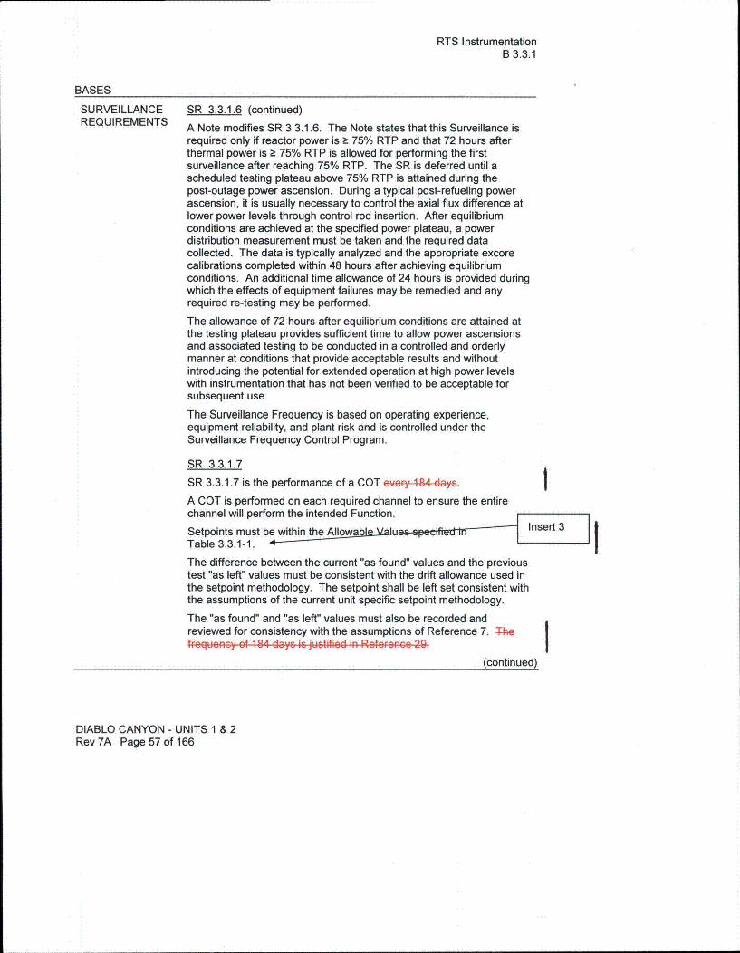
RTS InstrumentationB 3.3.1
BASES
SURVEILLANCE SR 3.3.1.6 (continued)
REQUIREMENTS A Note modifies SR 3.3.1.6. The Note states that this Surveillance is
required only if reactor power is a 75% RTP and that 72 hours afterthermal power is a 75% RTP is allowed for performing the firstsurveillance after reaching 75% RTP. The SR is deferred until ascheduled testing plateau above 75% RTP is attained during thepost-outage power ascension. During a typical post-refueling powerascension, it is usually necessary to control the axial flux difference atlower power levels through control rod insertion. After equilibriumconditions are achieved at the specified power plateau, a powerdistribution measurement must be taken and the required datacollected. The data is typically analyzed and the appropriate excorecalibrations completed within 48 hours after achieving equilibriumconditions. An additional time allowance of 24 hours is provided duringwhich the effects of equipment failures may be remedied and anyrequired re-testing may be performed.
The allowance of 72 hours after equilibrium conditions are attained atthe testing plateau provides sufficient time to allow power ascensionsand associated testing to be conducted in a controlled and orderlymanner at conditions that provide acceptable results and withoutintroducing the potential for extended operation at high power levelswith instrumentation that has not been verified to be acceptable forsubsequent use.
The Surveillance Frequency is based on operating experience,equipment reliability, and plant risk and is controlled under theSurveillance Frequency Control Program.
SR 3.3.1.7
SR 3.3.1.7 is the performance of a COT eve•y484 da. y
A COT is performed on each required channel to ensure the entirechannel will perform the intended Function.
Setpoints must be within the Allowa Insert 3
Table 3.3.1-1. IThe difference between the current "as found" values and the previoustest "as left" values must be consistent with the drift allowance used inthe setpoint methodology. The setpoint shall be left set consistent withthe assumptions of the current unit specific setpoint methodology.
The "as found" and "as left" values must also be recorded andreviewed for consistency with the assumptions of Reference 7. Thef..q..eucc' of 184 days is justifiod in Reforenco 29 I
(continued)
DIABLO CANYON - UNITS 1 & 2Rev 7A Page 57 of 166

RTS InstrumentationB 3.3.1
BASES
SURVEILLANCE SR 3.3.1.7 (continued)REQUIREMENTS SR 3.3.1.7 is modified by two notes. Note 1 provides a 4 hour delay in
the requirement to perform this Surveillance for source rangeinstrumentation when entering MODE 3 from MODE 2. This Noteallows a normal shutdown to proceed without a delay for testing inMODE 2 and for a short time in MODE 3 until the RTBs are open andSR 3.3.1.7 is no longer required to be performed. If the unit is to be inMODE 3 with the RTBs closed for > 4 hours this Surveillance must beperformed prior to 4 hours after entry into MODE 3. Note 2 requiresthat the quarterly COT for the source range instrumentation shallinclude verification by observation of the associated permissiveannunciator window that the P-6 and P-10 interlocks are in theirrequired state for the existing unit conditions. If this surveillance or ifSR 3.3.1.8 has been performed within the previous 184 days, therequirements of this surveillance are satisfied.
The Surveillance Frequency is baed Gn ope.ating eXperien,•..p . ,ment reliability, and plant rFik and is controlled under the I
Surveillance Frequency Control Program.
SR 3.3.1.8
SR 3.3.1.8 is the performance of a COT as described in SR 3.3.1.7 it ismodified by the same Note that this test shall include verification thatthe P-6 and P-1 0 interlocks are in their required state for the existingunit conditions by observation of the associated permissive annunciatorwindow. The Frequency is modified by a Note that allows thissurveillance to be satisfied if it has been performed within 184 days ofthe Frequencies prior to reactor startup, 12 hours after reducing powerbelow P-10, and four hours after reducing power below P-6, asdiscussed below. The Frequency of "prior to startup" ensures thissurveillance is performed prior to critical operations and applies to thesource, intermediate and power range low instrument channels. TheFrequency of "12 hours after reducing power below P-10" (applicableto intermediate and power range low channels) and "4 hours afterreducing power below P-6" (applicable to source range channels)allows a normal shutdown to be completed and the unit removed fromthe MODE of Applicability for this surveillance without a delay toperform the testing required by this surveillance. The Frequencythereafter applies if the plant remains in the MODE of Applicability afterthe initial performances of prior to reactor startup, 12 hours afterreducing power below P-10, and four hours after reducing power belowP-6. The MODE of Applicability for this surveillance is < P-10 for thepower range low and intermediate range channels and < P-6 for thesource range channels.
(continued)
DIABLO CANYON - UNITS 1 & 2Rev 7A Page 58 of 166

RTS InstrumentationB 3.3.1
BASES
SURVEILLANCE SR 3.3.1.8 (continued)REQUIREMENTS Once the unit is in MODE 3, this surveillance is no longer required. If
power is to be maintained < P-10 for more than 12 hours or < P-6 formore than 4 hours, then the testing required by this surveillance mustbe performed prior to the expiration of the 12 hour or 4 hour limit, asapplicable. These time limits are reasonable, based on operatingexperience, to complete the required testing or place the unit in aMODE where this surveillance is no longer required. This test ensuresthat the NIS source, intermediate, and power range low channels areOPERABLE prior to taking the reactor critical and after reducing powerinto the applicable MODE (< P-10 or < P-6) for the periods discussedabove. The Surveillance Frequency is based on operating experience,equipment reliability, and plant risk and is controlled under theSurveillance Frequency Control Program.
SR 3.3.1.9
SR 3.3.1.9 is the performance of a TADOT. The SurveillanceFrequency is based on operating experience, equipment reliability, andplant risk and is controlled under the Surveillance Frequency ControlProgram.
The SR is modified by a Note that excludes verification of setpointsfrom the TADOT. Since this SR applies to RCP undervoltage andunderfrequency relays, setpoint verification requires elaborate benchcalibration and is accomplished during the CHANNEL CALIBRATION.
SR 3.3.1.10CHANNEL CALIBRATION is a complete check of the instrument loop,including the sensor. The test verifies that the channel responds to ameasured parameter within the necessary range and accuracy.
CHANNEL CALIBRATIONS must be performed co t ht Insert 3assumptions of the DCPP setpoint methodology. he difference tbetween the current "as found" values and the previous test "as left"values must be consistent with the drift allowance used in the setpointmethodology.
Whenever an RTD is replaced in Functions 6, 7, or 14, the nextrequired CHANNEL CALIBRATION of the RTDs is accomplished by aninplace cross calibration that compares the other sensing elementswith the recently installed sensing element.The Surveillance Frequency is basod ORn oprating ePerieGe,•,.u. iment eliability, and plant Fisk and it controlled under the ISurveillance Frequency Control Program.
SR 3.3.1.10 is modified by a Note stating that this test shall includeverification that the time constants are adjusted to the prescribedvalues where applicable.
(continued)
DIABLO CANYON - UNITS 1 & 2Rev 7A Page 59 of 166
RTS InstrumentationB 3.3.1
BASES
SURVEILLANCE SR 3.3.1.15REQUIREMENTS SR 3.3.1.15 is the performance of a TADOT of Turbine Trip Functions.
(continued) This TADOT is performed prior to exceeding the P-9 interlock
whenever the unit has been in MODE 3. This Surveillance is notrequired if it has been performed within the previous 31 days.Verification of the Trip Setpoint does not have to be performed for thisSurveillance. Performance of this test will ensure that the turbine tripFunction is OPERABLE prior to exceeding the P-9 intfrlock.
SR 3.3.1.16
SR 3.3.1.16 verifies that the individual channel/train actuation responsetimes are less than or equal to the maximum values assumed in theaccident analysis. Response time testing acceptance criteria and theindividual functions requiring RESPONSE TIME verification areincluded in Equipment Control Guideline (ECG) 38.1. Individualcomponent response times are not modeled in the analyses.
The analyses model the overall or total elapsed time, from the point atwhich the parameter exceeds the trip setpoint value at the sensor tothe point at which the equipment reaches the required functional state(i.e., control and shutdown rods fully inserted in the reactor core).
For channels that include dynamic transfer Functions (e.g., lag,lead/lag, rate/lag, etc.), the response time test may be performed withthe transfer Function set to one, with the resulting measured responsetime compared to the appropriate FSAR response time. Alternately,the response time test can be performed with the time constants set totheir nominal value, provided the required response time is analyticallycalculated assuming the time constants are set at their nominal values.The response time may be measured by a series of overlapping testssuch that the entire response time is measured.
The response time testing for the SG water level low-low does notinclude trip time delays. Response times include the transmitters,cagIe-24p.Process pProtection System cabinets, solid state protectionsystem cabinets, and actuation devices only. This reflects theresponse times necessary for THERMAL POWER in excess of 50percent RTP. For those functions without a specified response time,SR 3.3.1.16 is not applicable.
(continued)
DIABLO CANYON - UNITS 1 & 2Rev 7A Page 62 of 166

RTS InstrumentationB 3.3.1
BASES
SURVEILLANCE SR 3.3.1.16 (continued)REQUIREMENTS SR 3.3.1.16 is modified by a Note stating that neutron detectors are
excluded from RTS RESPONSE TIME testing. This Note is necessarybecause of the difficulty in generating an appropriate detector inputsignal. Excluding the detectors is acceptable because the principles ofdetector operation ensure a virtually instantaneous response. Thesource range preamplifiers are also excluded. This is acceptablebecause the principles of operation of the preamplifier have beenevaluated and a determination made that there are no credible failuremechanisms that could affect response time that would not be detectedduring routine testing. Response time of the neutron flux signal portionof the channel shall be measured from detector output or input to thefirst electronic component in the channel, exclusive of the preamplifier.
REFERENCES 1. FSAR, Chapter 7.
2. FSAR, Chapter 6.
3. FSAR, Chapter 15.
4. IEEE Std. 279-1971.
5. 10 CFR 50.49.
6. IEEE Std. 603-1991, "Standard Criteria for Safety Systems forNuclear Power Generating Stations"BlaI
7. WCAP-10271-P-A, Supplement 2, Rev. 1, June 1990.
8. WCAP 13632 - PA-1, Rev. 2 "Elimination of Pressure SensorResponse Time Testing Requirements."
9. FSAR, Chapter 9.2.7 & 9.2.2.
10. FSAR, Chapter 10.3 & 10.4
11. FSAR, Chapter 8.3.
12. DCM S-38A, "Plant Protection System"
13. WCAP-13878, "Reliability of Potter & Brumfield MDR Relays",June 1994.
14. WCAP-1 3900, "Extension of Slave Relay Surveillance Testintervals", April 1994.
15. WCAP-14117, "Reliability Assessment of Potter and BrumfieldMDR Series Relays."
16. WCAP-9226, "Reactor Core Response to Excessive SecondarySteam Releases," Revision 1, January 1978.
(continued)
DIABLO CANYON - UNITS 1 & 2Rev 7A Page 64 of 166

RTS InstrumentationB 3.3.1
BASES
REFERENCES(continued)
17. WCAP-1 1082, "Westinghouse Setpoint Methodology for ProtectionSystems, Diablo Canyon Units I and 2, 24 Month Fuel CycleEvaluation, and-Replacement Steam Generator, and ProcessProtection System Replacement" $eptembeiMONTH 2007-YEAR.
18. NSP-1-20-13F Unit I "Turbine Auto Stop Low Oil Pressure."
19. NSP-2-20-13F Unit 2 "Turbine Auto Stop Low Oil Pressure."
20. J-1 10 "24 Month Fuel Cycle Allowable Value Determination /Documentation and ITDP Uncertainty Sensitivity."
21. IEEE Std. 338-1977.
22. License Amendment 61/60, May 23, 1991.
23. Westinghouse Technical Bulletin ESBU-TB-92-14-R1,"Decalibration Effects of Calorimetric Power Measurements on theNIS High Power Reactor Trip at Power Levels less than 70%RTP," dated February 6, 1996.
24. DCPP NSSS Calculation N-212, Revision 1.
25. License Amendments 157/157, June 2, 2003.
26. WCAP-12472-P-A, "BEACON Core Monitoring and OperationsSupport System," August 1994.
27. WCAP-14036-P-A, Revision 1, "Elimination of Periodic ProtectionChannel Response Time Tests," October 1998.
28. WCAP-14333-P-A, Revision 1, "Probabilistic Risk Analysis of theRPS and ESFAS Test Times and Completion Times," October1998.
29. WCAP-15376-P-A, Revision 1, "Risk-Informed Assessment of theRTS and ESFAS Surveillance Test Intervals and Reactor TripBreaker Test and Completion Times," March 2003.
30. WCAP-1 1394-P-A, "Methodology For The Analysis of the DroppedRod Event," January, 1990
31. License Amendments 205/206, April 29, 2009
32. WCAP-16769-P Revision 1, "Westinghouse SSPS Universal LogicBoard Replacement Summary Report6D30225G01/G02/G03/G04," July 2008.
I
DIABLO CANYON - UNITS 1 & 2Rev 7A Page 65 of 166

ESFAS InstrumentationB 3.3.2
BASES
BACKGROUND During AOOs, which are those events expected to occur one or more(continued) times during the unit life, the acceptable limits are:
1. The Departure from Nucleate Boiling Ratio (DNBR) shall bemaintained above the Safety Limit (SL) value to prevent departurefrom nucleate boiling (DNB).
2. Fuel centerline melt shall not occur, and
3. The RCS pressure SL of 2750 psia shall not be exceeded.
Operation within the SLs of Specification 2.0, "Safety Limits (SLs),"also maintains the above values and assures that offsite dose will bewithin the 10 CFR 50 and 10 CFR 100 criteria during AOOs.
Accidents are events that are analyzed even though they are notexpected to occur during the unit life. The acceptable limit duringaccidents is that offsite dose shall be maintained within an acceptablefraction of 10 CFR 100 limits. Different accident categories are alloweda different fraction of these limits, based on probability of occurrence.Meeting the acceptable consequences for that event is consideredhaving acceptable consequences for that event. However, thesevalues and their associated NTSPs are not considered to be LSSS asdefined in 10 CFR 50.36.
The ESFAS instrumentation is segmented into three distinct butinterconnected modules as identified below:
" Field transmitters or process sensors and instrumentation: providea measurable electronic signal based on the physicalcharacteristics of the parameter being measured;
" Signal processing equipment including dDigital Process pErotectionsystem, field contacts, and protection channel sets: provide signalconditioning, bistable setpoint comparison, process algorithmactuation, compatible electrical signal output to protection systemdevices, and control board/control room/miscellaneous indications;and
* Solid State Protection System (SSPS) including input, logic, andoutput bays: initiates the proper unit shutdown or engineeredsafety feature (ESF) actuation in accordance with the defined logicand based on the bistable outputs from the signal process controland protection system. The residual heat removal pump trip orrefueling water storage tank level-low signal is not processed by theSSPS. The associated relays are located in the residual heatremoval pumps control system.
(continued)
DIABLO CANYON - UNITS 1 & 2Rev 7A Page 68 of 166

ESFAS InstrumentationB 3.3.2
BASES
BACKGROUND Signal Processing Equipment (continued)
Generally, if a parameter is used for input to the SSPS and a controlfunction, four channels with a two-out-of-four logic are sufficient toprovide the required reliability and redundancy. In the case of theDigital Feedwater Control System (DFWCS), the median/signal select(MSS) feature prevents control/protection interaction even though thereare only three inputs and 2-out-of-3 logic. The circuit must be able towithstand both an input failure to the control system, which may thenrequire the protection function actuation, and a single failure in theother channels providing the protection function actuation. Again, asingle failure will neither cause nor prevent the protection functionactuation.
These requirements are described in IEEE-279-1971 (Ref. 4) andIEEE-603-1991 for the Process Protection System (Ref. 6). The actualnumber of channels required for each unit parameter is specified inReference 2.
Each of the four Process Protection System protection channel setscontains a microprocessor-based Tricon programmable logic controllersubsystem comprised of three separate legs and a field programmablegate array-based Advanced Logic System (ALS) subsystem comprisedof an A core and a B core. The protection set protection function canbe Performed by any of the three Tricon legs and by either the ALS Acore or B core. At least one Tricon leg and one ALS core are reguiredfor a protection set to perform all required protection functions requiredfor that protection set.
The channels are designed such that testing required to be performedat power may be accomplished without causing an ESF actuation. TheProcess Protection System is designed to permit any one channel tobe tested and maintained at power in a bypass mode.
If a channel has been bypassed for any purpose, the bypass iscontinuously indicated in the control room as required by applicablecodes and standards. As an alternate to testing in the bypass mode,testing in the trip mode is also possible and permitted.
(continued)
DIABLO CANYON - UNITS 1 & 2Rev 7A Page 70 of 166

ESFAS InstrumentationB 3.3.2
BASES
BACKGROUND Trip Setpoints and Allowable Values(continued) The Trip Setpoints are the nominal values at which the bistables are
set. Any bistable is considered to be properly adjusted when the "asleft" value is within the two-sided tolerance band for calibrationaccuracy.
The Trip Setpoints used in the bistables are based on the analyticallimits stated in Reference 2. The selection of these Trip Setpoints issuch that adequate protection is provided when all sensor andprocessing time delays are taken into account. To allow for calibrationtolerances, instrumentation uncertainties, instrument drift, and severeenvironment errors for those ESFAS channels that must function inharsh environments as defined by 10 CFR 50.49 (Ref. 5), the TripSetpoints and Allowable Values specified in Table 3.3.2-1 in theaccompanying LCO are conservatively adjusted with respect to theanalytical limits. A detailed description of the methodology used tocalculate the Trip Setpoints, including their explicit uncertainties, isprovided in WCAP-1 1082, "Westinghouse Setpoint Methodology forProtection Systems Diablo Canyon Units 1 & 2, 24 Month Fuel Cycle,a•rd-Replacement Steam Generator Evaluation, and ProcessProtection System Replacement" Septe befMONTH 2007YEAR(Ref. 12), calculation J-54 (Ref. 13) and calculation J-110 (Ref. 14).Interlock setpoints are nominal values provided in the PLS(Westinghouse Precautions Limitations and Setpoints) and theirallowable values are calculated in Calculation J-1 10 Rev. 7 (Ref. 14).For Function 5.b in TS Table 3.3.2-1, the magnitudes of theseuncertainties are factored into the determination of the NTSP andcorresponding AV. The actual nominal Trip Setpoint entered into thebistable is more conservative than that specified by the AllowableValue to account for Rack Drift and Rack Measuring and TestEquipment uncertainties. The calibration tolerance, after conversion,should correspond to the rack comparator setting accuracy defined inthe latest setpoint study. For Function 5.b in TS Table 3.3.2-1, the AVserves as the Technical Specification OPERABILITY limit for purposesof the COT. One example of such a change in measurement error isdrift during the surveillance interval. If the measured setpoint isconservative with respect to the Allowable Value, the bistable isconsidered OPERABLE. For Function 5.b in TS Table 3.3.2-1, notethat, although a channel is OPERABLE under these circumstances, thesetpoint must be left adjusted to within the established as-left criteriaand confirmed to be operating within the statistical allowances of theuncertainty terms assigned.
(continued)
DIABLO CANYON - UNITS 1 & 2Rev 7A Page 71 of 166

ESFAS InstrumentationB 3.3.2
BASES
APPLICABLESAFETYANALYSES, LCO,andAPPLICABILITY
(continued)
Failure of any instrument renders the affected channel(s) inoperableand reduces the reliability of the affected Functions.
The LCO generally requires OPERABILITY of four or three channels ineach instrumentation function and two channels in each logic andmanual initiation function. The two-out-of-three and the two-out-of-fourconfigurations allow one channel to be tripped, cut-out or bypassedduring maintenance or testing without causing an ESFAS initiation.Two logic or manual initiation channels are required to ensure no singrandom failure disables the ESFAS Insert 4The required channels of ESFAS instrumentation provide unitprotection in the event of any of the analyzed accidents. ESFASprotection functions are as follows:
1. Safety Iniection
Safety Injection (SI) provides two primary functions:
1. Primary side water addition to ensure maintenance or recoveryof reactor vessel water level (coverage of the active fuel forheat removal, clad integrity, and for limiting peak cladtemperature to < 2200°F); and
2. Boration to ensure recovery and maintenance of SDM (keff< 1.0).
These functions are necessary to mitigate the effects of highenergy line breaks (HELBs) both inside and outside ofcontainment. The SI signal is also used to initiate otherFunctions such as:
S
S
0
0
0
Phase A Isolation;Containment Ventilation Isolation;
Reactor Trip;Turbine Trip from Reactor Trip with P-9;Feedwater Isolation and Feedwater Pump Turbine Trip;
* Start of motor driven auxiliary feedwater (AFW) pumps;* Control room ventilation to pressurization mode via Phase
A isolation, and Auxiliary Building to "Building andSafeguards or Safeguards Only" mode;
* Start of the diesel generators (DGs) and transfer to thestartup bus;
* Start of the containment fan cooler units (CFCUs) in lowspeed;
* Start of the component cooling water and auxiliary saltwater pumps;
* Input to containment spray pump and discharge valve auto,start (with containment spray signal);
" Isolate SG sample blowdown lines.(continued)
DIABLO CANYON - UNITS 1 & 2Rev 7A Page 75 of 166

ESFAS InstrumentationB 3.3.2
BASES
SURVEILLANCEREQUIREMENTS
(continued)
SR 3.3.2.2
SR 3.3.2.2 is the performance of an ACTUATION LOGIC TEST. TheSSPS is tested using the semiautomatic tester. The train being testedis placed in the bypass condition, thus preventing inadvertentactuation. Through the semiautomatic tester, all possible logiccombinations, with and without applicable permissives, are tested foreach protection function. In addition, the master relay coil is pulsetested for continuity. This verifies that the logic modules areOPERABLE and that there is an intact voltage signal path to themaster relay coils. The Surveillance Frequency is based on operatingexperience, equipment reliability, and plant risk and is controlled underthe Surveillance Frequency Control Program.
SR 3.3.2.3 - Not used
SR 3.3.2.4
SR 3.3.2.4 is the performance of a MASTER RELAY TEST. TheMASTER RELAY TEST is the energizing of the master relay, verifyingcontact operation and a low voltage continuity check of the slave relaycoil. Upon master relay contact operation, a low voltage is injected tothe slave relay coil. This voltage is insufficient to pick up the slaverelay, but large enough to demonstrate signal path continuity. The timeallowed for the testing (4 hours) is justified in Reference 8. TheSurveillance Frequency is based on operating experience, equipmentreliability, and plant risk and is controlled under the SurveillanceFrequency Control Program.
SR 3.3.2.5
SR 3.3.2.5 is the performance of a COT.
A COT is performed on each required channel to ensure the entirechannel will perform the intended Function. Setpoints must be foundconservative with respect to the Allowable Insert 3Table 3.3.2-1. - I
The difference between the current "as found" values and the previoustest "as left" values must be consistent with the drift allowance used inthe setpoint methodology. The setpoint shall be left set consistent withthe assumptions of the current unit specific setpoint methodology.
The "as found" and "as left" values must also be recorded andreviewed for consistency with the assumptions of the surveillanceinterval extension analysis (Ref. 8) when applicable.
The Surveillance Frequency is based 9.R- Merv• I V t Pae-I--. I1--..I . .--. I--. il.-- ICAuIDHAuRAR FRullRiIImv zRin uMjRx RIK wriu u-crniroited undoer tne
Surveillance Frequency Control Program.
The next two paragraphs apply only to Function 5.b, an SL-LSSSfunction, in TS Table 3.3.2-1.
(continued)
DIABLO CANYON - UNITS 1 & 2Rev 7A Page 114 of 166

ESFAS InstrumentationB 3.3.2,
BASES
SURVEILLANCEREQUIREMENTS
(continued)
SR 3.3.2.7- Not used
SR 3.3.2.8
SR 3.3.2.8 is the performance of a TADOT. This test is a check of theManual Actuation Functions (except AFW; see SR 3.3.2.13). EachManual Actuation Function is tested up to, and including, the masterrelay coils. In some instances, the test includes actuation of the enddevice (i.e., pump starts, valve cycles, etc.). The SurveillanceFrequency is based on operating experience, equipment reliability, andplant risk and is controlled under the Surveillance Frequency ControlProgram. The SR is modified by a Note that excludes verification ofsetpoints during the TADOT for manual initiation Functions. Themanual initiation Functions have no associated setpoints.
SR 3.3.2.9
SR 3.3.2.9 is the performance of a CHANNEL CALIBRATION.
CHANNEL CALIBRATION is a complete check of the instrument loop,including the sensor. The test verifies that the channel responds tomeasured parameter within the necessary range and accuracy. Insert 3
CHANNEL CALIBRATIONS must be performed consiste i h theassumptions of the unit specific setpoint methodology. The differencebetween the current "as-found" values and the previous test "as-left"values must be consistent with the drift allowance used in the setpointmethodology.
(continued)
DIABLO CANYON - UNITS 1 & 2Rev7A Page 116 of 166

ESFAS InstrumentationB 3.3.2
BASES
SURVEILLANCE SR 3.3.2.9 (continued)REQUIREMENTS Whenever an RTD is replaced in Function 6.d., the next required
CHANNEL CALIBRATION of the RTDs is accomplished by an inplacecross calibration that compares the other sensing elements with therecently installed sensing element.
The Surveillance Frequency is basod on oporating .xp•.Fi...,c.uiPmeR. t Fcliability, .d p"'nt rick and i6 controlled under the ISurveillance Frequency Control Program.
This SR is modified by a Note stating that this test should includeverification that the time constants are adjusted to the prescribedvalues where applicable.
The next two paragraphs apply only to Function 5.b, an SL-LSSSfunction, in TS Table 3.3.2-1.
SR 3.3.2.9 for Function 5.b is modified by two notes as identified inTable 3.3.2-1. The first Note requires evaluation of channelperformance for the condition where the as-found setting for thechannel setpoint is outside its as-found tolerance but conservative withrespect to the AV. Evaluation of instrument performance will verify thatthe instrument will continue to behave in accordance with safetyanalysis assumptions. The purpose of the assessment is to ensureconfidence in the instrument performance prior to returning theinstrument to service. The performance of these channels will beevaluated under the DCPP Corrective Action Program. Entry into theCorrective Action Program will ensure required review anddocumentation of the condition for continued OPERABILITY. Thesecond Note requires that the as-left setting for the instrument bereturned to within the as-left tolerance of the NTSP. Where a setpointmore conservative than the NTSP is used in the plant surveillanceprocedures, the as-left and as-found tolerances, as applicable, will beapplied to the surveillance procedure setpoint. This will ensure thatsufficient margin to the SL and/or Analytical Limit is maintained. If theas-left instrument setting cannot be returned to a setting within the as-left tolerance, then the instrument channel shall be declaredinoperable.
The second Note also requires that the NTSP and the methodologiesfor calculating the as-left and the as-found tolerances be in the ECGs.
(continued)
DIABLO CANYON - UNITS 1 & 2Rev 7A Page 117 of 166

ESFAS InstrumentationB 3.3.2
BASES
SURVEILLANCEREQUIREMENTS
(continued)
SR 3.3.2.12
SR 3.3.2.12 is the performance of an ACTUATION LOGIC TEST.This SR is applied to the RHR Pump Trip on RWST Level-Lowactuation logic and relays which are not processed through the SSPS.The Surveillance Frequency is based on operating experience,equipment reliability, and plant risk and is controlled under theSurveillance Frequency Control Program.
SR 3.3.2.13
SR 3.3.2.13 is the performance of a TADOT. This test is a check ofthe Manual Actuation Function for AFW. Each Manual ActuationFunction is tested up to, and including, the master relay coils. In someinstances, the test includes actuation of the end device (i.e., pumpstarts, valve cycles, etc.). The Surveillance Frequency is based onoperating experience, equipment reliability, and plant risk and iscontrolled under the Surveillance Frequency Control Program. The SRis modified by a Note that excludes verification of setpoints during theTADOT for manual initiation Functions. The manual initiationFunctions have no associated setpoints.
REFERENCES 1. FSAR, Chapter 6.
2. FSAR, Chapter 7.
3. FSAR, Chapter 15.
4. IEEE Std.279-1971.
5. 10 CFR 50.49.
6. IEEE Std. 603-1991, "Standard Criteria for Safety Systems forNuclear Power Generating Stations"Blan
7. WCAP-1 3900, "Extension of Slave Relay Surveillance Testintervals", April 1994
8. WCAP-1 0271-P-A, Supplement 2, Rev. 1, June 1990.
I
(continued)
DIABLO CANYON - UNITS 1 & 2Rev 7A Page 120 of 166

ESFAS InstrumentationB 3.3.2
BASES
REFERENCES(continued)
9. WCAP-13878, "Reliability of Potter & Brumfield MDR Relays",June 1994.
10. WCAP-14117, "Reliability Assessment of Potter and BrumfieldMDR Series Relays."
11. WCAP-1 3632-P-A, Revision 2, "Elimination of Pressure SensorResponse Time Testing Requirements," January 1996.
12. WCAP-1 1082, "Westinghouse Setpoint Methodology for ProtectionSystems, Diablo Canyon Units 1 and 2, 24 Month Fuel Cycle, andReplacement Steam Generator Evaluation, and ProcessProtection System Replacement" MONTHSeptembeF YEAR2007.
13. Calculation J-54, "Nominal Setpoint Calculation for Selected PLSSetpoints."
14. J-1 10, "24 Month Fuel Cycle Allowable Value Determination /Documentation and ITDP Uncertainty Sensitivity."
15. License Amendment 61/60, May 23, 1991.
16. WCAP-14036-P-A, Revision 1, "Elimination of Periodic ProtectionChannel Response Time Tests," October 1998.
17. WCAP-14333-P-A, Revision 1, "Probabilistic Risk Analysis of theRPS and ESFAS Test Times and Completion Times,"October 1998.
18. WCAP-15376-P-A, Revision 1, "Risk-Informed Assessment of theRTS and ESFAS Surveillance Test Intervals and Reactor TripBreaker Test and Completion Times," March 2003.
19. 10 CFR 50.55a(h), "Protection and Safety Systems."
I
DIABLO CANYON - UNITS 1 & 2Rev 7A Page 121 of 166

Technical Specification Bases Inserts
Technical Specification Bases Section 3.3.1
Insert 1, Background
Each of the four Process Protection System protection channel sets contains a microprocessor-based Triconprogrammable logic controller subsystem comprised of three separate legs and a field programmable gatearray-based Advanced Logic System (ALS) subsystem comprised of an A core and a B core. The protectionset protection function can be performed by any of the three Tricon legs and by either the ALS A core or Bcore. At least one Tricon leg and one ALS core are required for a protection set to perform all requiredprotection functions required for that protection set.
Insert 2, Applicable Safety Analyses, LCO, and Applicability
For the RTS functions processed by the Process Protection System, at least one Tricon leg and one ALS coreare required for a protection set and associated instrumentation channels to be OPERABLE. If all threeTricon legs or both ALS cores in a protection set are out of service, the protection function cannot beperformed and the protection set and associated instrumentation channels are inoperable and the applicableConditions for the Table 3.3.1-1 Functions with an inoperable channel must be entered. One or two-out-of-three Tricon legs and one-out-of-two ALS cores in a protection set are sufficient to provide the protectionfunction. To maintain high reliability of the Process Protection System, the maximum time with one or twoTricon leg(s) out of service in a protection set is administratively controlled. To maintain high reliability anddiversity of the Process Protection System, the~maximum time with one ALS core out of service in a protectionset is administratively controlled.
Insert 3, Surveillance Requirements
Plant procedures verify that the instrument channel functions as required by verifying the "as left" and "asfound" settings are consistent with those established by the setpoint methodology.
Technical Specification Bases Section 3.3.2
Insert 3, Surveillance Requirements
Plant procedures verify that the instrument channel functions as required by verifying the "as left" and "asfound" settings are consistent with those established by the setpoint methodology.
Insert 4, Applicable Safety Analyses, LCO, and Applicability
For the ESFAS functions processed by the Process Protection System, at least one Tricon leg and one ALScore are required for a protection set and associated instrumentation channels to be OPERABLE. If all threeTricon legs or both ALS cores in a protection set are out of service, the protection function cannot beperformed and the protection set and associated instrumentation channels are inoperable and the appropriateConditions for the Table 3.3.2-1 Functions with an inoperable channel must be entered. One or two-out-of-three Tricon legs and one-out-of-two ALS cores in a protection set are sufficient to provide the protectionfunction. To maintain high reliability of the Process Protection System, the maximum time with one or twoTricon leg(s) out of service in a protection set is administratively controlled. To maintain high reliability anddiversity of the Process Protection System, the maximum time with one ALS core out of service in a protectionset is administratively controlled.