di s e ñ o d e v e h í c u l o ba j a sae - páginas - sae.pdf · his technical report consist on...
TRANSCRIPT

Diseño De vehículo Baja sae

UNIVERSIDAD AUTÓNOMA DE CIUDAD JUÁREZ
Ricardo Duarte JáquezRector
David Ramírez PereaSecretario General
Manuel Loera de la RosaSecretario Académico
Francisco López Hernández Director del Instituto de Ingeniería y Tecnología
Luis Enrique Gutiérrez CasasCoordinador General de Investigación y Posgrado
Ramón Chavira ChaviraDirector General de Difusión Cultural y Divulgación Científica

Universidad Autónoma de Ciudad Juárez
juan Miguel Díaz MenDoza
luis viDal Portilla
carlos FeliPe raMírez esPinoza
césar gonzález Pizón
ingeniería y tecnología
CoordinaCión General de investiGaCión y PosGrado
Diseño De vehículo Baja sae
Lisbeily Domínguez Ruvalcaba Coordinadora de la ColeCCión

Díaz Mendoza, Juan Miguel; Vidal Portilla, Luis; Ramírez Espinoza, Carlos Felipe; González Pizón, César.
Diseño de vehículo Baja SAE / Juan Miguel Díaz Mendoza, Luis Vidal Portilla, Carlos Felipe Ramírez Espinoza, César González Pizón. Ciu-dad Juárez, Chih. : Universidad Autónoma de Ciudad Juárez, 2013. (Colección Textos Universitarios, Serie Investigación)
32 p.; 30 cm.
Incluye bibliografía Colección Reportes Técnicos de Investigación ISbn: 978-607-7953-80-7Serie IIT, Vol. 6. ISbn: 978-607-520-017-0
Contenido:
1.– Introduction. 2.– Proposal. 3.– Methodology. 4.– Results. 5.– Con-clusions.
D. R. © Díaz Mendoza, Juan Miguel; Vidal Portilla, Luis; Ramírez Espinoza, Carlos Feli-pe; González Pizón, César.
La edición, diseño y producción editorial de este documento estuvo a cargo de la Direc-ción General de Difusión Cultural y Divulgación Científica, a través de la Subdirección de Publicaciones.

ínDiceResumen 7Abstract 9Palabras clave 10Usuarios potenciales 10Reconocimientos 10
i. introDuction
ii. ProPosal
Background 13
Theory framework 14Parameters 14Table1. Vehicle parameters 14Chassis roll cage requirements 15Engine requirements 15Suspension 15Steering system 16Brake system 16Electrical system 16Manufacturing 17

iii. MethoDology
Chassis frame 19Material 19
Table 2 20Chassis design 20Analysis 20Transmission design 21Gear box design 21
Figure 1 21Drive system: cvt (continuous variable transmission) 22
Figure 2 22Steering design 23Rack and pinion 23Brake system 23
Figure 3 23Physical considerations 24
Figure 4 24Suspension design 24Manufacturing 25
iv. results
v. conclusions
References

7
resuMen
Este proyecto tiene el propósito de desarrollar un prototipo de vehículo todo terreno. El diseño del vehículo estará enfocado a mejorar varios aspectos del desempeño global. Por lo tanto, se establecieron varios objetivos:
Mejorar el desempeño con el diseño de un nuevo reductor de engranes. ɶReducir peso del vehículo con un nuevo chasis. ɶDiseñar un nuevo sistema de suspensión. ɶDiseñar un nuevo sistema de dirección para mejorar la maniobrabilidad. ɶ
Se fabricará utilizando procesos manuales y automáticos tipo CnC. El proceso de diseño fue basado en la reglas que publica la Sociedad de Ingenie-
ros Automotrices de Estados Unidos (SAE). Esta reglas establecen lo requerimientos mínimos del diseño con el objetivo de cumplir con seguridad del piloto en la compe-tencia. El proyecto adicionalmente desarrolla habilidades de diseño y fabricación en los estudiantes que participan en el proyecto. Esto les permitirá adquirir habilidades para su desarrollo profesional cuando estén en la industria.
El diseño fue enfoca a obtener un vehículo que fuera mas ligero como se menciono anteriormente y se obtuvo de acuerdo a los resultados.
En resumen el proyecto fue terminado en tiempo y objetivos planteados al ini-cio del proyecto. El vehículo realizó pruebas de desempeño y resistencia básicas que cumplían con los objetivos propuestos.


9
aBstract
This project aims to develop a prototype of an ATV. The vehicle design will be focused on improving various aspects of overall performance. It is therefore established several objectives which are:
Improve performance with a new design of gear reducer. ɶReducing vehicle weight with a new chassis. ɶDesign a new suspension system. ɶDesign a new steering system for improved handling. ɶ
Which was made using manual processes and automatic type CnC.The design process was based on the rules published by the Society of Automo-
tive Engineers of America (SAE). These rules establish the minimum design require-ments in order to comply with driver safety in the competition. The project further develops skills in design and manufacturing students participating in the project. This will enable them to acquire skills for their professional development when they are in the industry.
The design was focused to obtain a vehicle that was much lighter as mentioned above and was obtained according to the results.
In summary, the project was completed on time and objectives at the beginning of the project. The vehicle tested for performance and basic resistance that met the objectives.

Diseño de vehículo Baja sae
10 Palabras claveMechanical design, manufacturing, improvement.
Usuarios potencialesPotential users of this project are students that are interested in automotive de-
sign, projects that requires information in automated process application.
Reconocimientos
Agradecemos a la universidad Autónoma de Ciudad Juárez y a las compañías bRP, El Milésimo, Y&D, Ergomed, Jidosha, Rino Metales, Ávila manufacturing, Le-yco, Dr. García, que apoyaron a financiar este proyecto. También queremos agrade-cer a los estudiantes que apoyaron en el desarrollo de este proyecto: Mayra nevá-rez, Eduardo Morales, Valentín Gallega, Ismael Pérez, Juan José Velázquez, néstor Santos, Enrique Duarte, Felipe Jiménez, Roberto Sierra, Roberto Alamillo, Jerónimo Huerta y Jaime Mendoza. Ya que sin el apoyo de todos ellos no su hubiera logrado la terminación de este proyecto.

Diseño de vehículo Baja sae 11
i. introDuction
Automotive design is one of the areas where engineering knowledge is ap-plied in several systems such chassis structural analysis, mechanism de-sign (brakes, transmission, steering, etc.), stress analysis, materials selec-tion and manufacturing.
The project bAJA SAE requires applying several analyses in the design process, which also needs physical testing on order to achieve a good design.
This project was developed with the purpose to design and manufacture an all terrain vehicle prototype. The University of Juarez has participated in a competi-tion called bAJA SAE in the past three years in which the competition results have been improved each year. The project also required to use the SAE rules that each year are published for the competition and used to assure that vehicle design meets them.
There are several aspects that the design must meet in order to comply with the rules requirements and participate. based on this rules and order aspects the project was initiated and completed with the validation of the prototype.
There are several aspects that the vehicle must meet with are the following:
Must meet safety design. This means rollover protection, brakes and lighting. ɶMeet performance criteria’s. ɶMeet building standards to comply with safety. ɶMeet materials standards to comply with safety ɶ
The vehicle for this project is important to design and improve over the past proto-type in several areas. The main goals in this vehicle design are the following:
Improve performance by design a new gearbox. ɶReduce vehicle weight. ɶDesign a new suspension system. ɶDesign a new steering system to improve maneuverability. ɶ

12
Diseño de vehículo Baja sae
The goals will be achieved through several steps and work among the research team with the support of the students.
Once revise the project requirements is needed to develop a work including con-cept design, detailed design, mechanical analysis (stress, dynamic and others), and fabrication (manual and automated processes (CnC , EDM).

Diseño de vehículo Baja sae 13
ii. ProPosal
Background
This technical report consist on the description of the four-wheel vehicle that was being designed and constructed with the purpose of participate on the competition baja SAE 2011. The design objective is a light but strong ve-hicle based on the regulations for the competition and dedicated to reach the
expected results on performance and cost.The society of Automotive Engineers (SAE) is the organization that sponsors and or-
ganizes the baja SAE competition. This is an international competition that promotes design, manufacturing and project management skills on the students that participate on the project with support of a academic advisor. The competition was established in 1976 in the university of South Carolina under supervision of the Dr. J. F Stevens. Since then, this event has become a premier design event for engineering students.
The main objectives of this design project are to enhance vehicle performance and cost, meeting the rules requirements.
Some of these requirements require using engineering knowledge and tools such manufacturing technology applications, CAD/CAM/CAE, cost analysis, etc. Also the de-sign requires performing validation and test to assure vehicle will stand the completion tests. The vehicle design consist on a frame chassis that main objective is to design the cockpit to withstand rollover situation which prevents that pilot suffers any injuries. A key part of the performance is the engine, which is the same for all participants.
Finally there is the score process for each of the events and a final score is giving to each participant and ranked among all registered in the event. Usually 100 or more universities participate on each of the events that SAE sponsors on the bAJA SAE category.
Design in the automotive industry is one of the most challenge for a new product because requires a good design process and fabrication which will assure a good per-formance and reliability. Since the car has several systems, each requires a particu-lar approach in order to meet car design requirements.

14
Diseño de vehículo Baja sae ii. ProPosal
These systems, which we list as follows:
Chassis: the main structural element in the car. ɶSuspension: System, which controls the ride, comfort as well the maneuver- ɶability of the car.Power train: This system provides the energy to move the car at specific speed ɶbased on weight and dimension.Transmission: Provides the ratio between power and tires assuring a good ɶtraction and speed.brakes: This system is very critical for the safety of the vehicle when used by ɶthe final user of the vehicle.Lights: System the provides lighting capability and safety since is used an ɶvisual control to others.Steering: The steering system is a key part of the front suspension since en- ɶhance the maneuverability of the vehicle.
Considering all these requirements for the car the design process was developed for the car, which included body panels.
Theory framework
Parameters
The parameters that are defined for the car are established in the bAJA SAE rules, which are shown in the following chart. Table 1.
Table1. Vehicle parameters
Vehicle Dimensional Requirement
MIN MAX
Wheelbase AD 108 IN
Overall height 52 IN AD
Front track AD 64 IN
Rear track AD 64 IN
Engine power AD 10 HP
Ground Clearance AD 12 IN
Material 1 IN DIAM AD
Others requirements are hitch points, electrical system, safety guards, brake sys-tem, fuel system, fasteners, and suspension and steering system.

Diseño de vehículo Baja sae
15
ii. ProPosal
Chassis roll cage requirements
Parameters for the chassis requirements are several which will be describe in order to properly design this structure and analysis from the mechanical and stress performance.
Cockpit. The cockpit is the key section of the vehicle since has the most important job in the car design: protect the pilot’s physical integrity during a rollover situation. So should be very stiff and light at the same time.
Some these requirements are as follows:
Safety of the pilot in case of rollover ɶSafety in case of frontal or rear crash ɶDimensions to fir 95% of the percentile of the users. ɶMaterial that meets specifications of steel SAE1018 with 1in diameter and ɶ3.00 mm thickness.
Additionally structural analysis will be required.
Engine Requirements
The vehicle engine requirements are established in the SAE rules(1) which men-tion that only briggs & Stratton (b&S) engines with the following parts number should be used:
baja Acceptable Engines 20S332 0036-F1 205432 0536-E9 205332 0536-E9 205332 0536-b1
The engine is rated as a 10 hp power and according to the rules no modifications are allowed the modify engine performance. An other key point is rpm must regu-lated to top 3800 rpm since b&S will verify it prior to test.
Suspension
The suspension system requires a new design that allows better maneuverability and better steering. The basic requirements are to withstand track terrain and de-sign. Since there are no additionally requirements in the rules, are at the team option the improvements in design and manufacturing requirements.

16
Diseño de vehículo Baja sae ii. ProPosal
Steering system
The steering systems is also requiring a basic approach, which is safety of the vehicle, and withstand track terrain and design. no further requirements are re-quested.
Brake system
The requirements of the brake system are two and they consist in the following:
Able to block all four wheels at the same time. ɶThe hydraulic system must have a master cylinder with independent circuits ɶfor front and rear wheels.
Must be shown the proper selection was made in order to assure safety of the per-son and vehicle.
Electrical system
The electrical system requires the following items:
Should use to killing switches for emergency shutdown and the switches must ɶbe placed on in front and one in the back of the vehicle.For lights an additional battery should be used, and the lights used must meet ɶSAE “U” or “S” rated.
Finally there are other areas where is require to meet engineering standards which will assure safety of the vehicle. Some of these are:
Fasteners. Should meet a minimum of SAE grade 5 according to the rules. ɶSafety equipment: Pilot restrains systems must meet either SFI Specification ɶ16.5/16.1, or FIA specification 8853/98.Guards: the body panels and other guards should be design to protect pilot ɶfrom coming injured during a crash situation and protect moving parts from injure a person in case of failure.

Diseño de vehículo Baja sae
17
ii. ProPosal
Manufacturing
Manufacturing engineering is technology that applies techniques or equipment to improve processes. During the project three main processes will be used to manufac-ture the main components. The three processes are:
MIG welding.- This welding process is defined as metal inert gas process which ɶuses automatic wire feed in the welding process. This process has given good results in previous projects.Turning.- This is one of the process that many of the parts will be fabricated. ɶThe current application will be on manual process.CnC process. This automated process has different field such, turning, milling, ɶdrilling, EDM (electro discharge machine) and others. The project is consider-ing milling and wire EDM mainly on suspension and gear box assemblies.

19
iii. MethoDology
The design development and fabrication was made in a team scope where the professors and students design and manufacture the key components of the car. Each of the systems was developed having in main the objec-tives of the car.
Chassis frame
The chassis of a vehicle is the armor on which are mounted and holding all the mechanisms, supporting the weight of some of them and some other components are hanging of it. The most important objective of our chassis design is to ensure driver safety, but it is also a priority for the structure to be as light as possible. For those reasons, the two most important things were considered on the makeup of the struc-ture are the weight and the stiffness.
Material
Due to the SAE rules, the frame must be made of circular steel tubing with an outside diameter of 25mm (1 in) and a wall thickness of 3mm (0.120 in) and a carbon content of at least 0.18% (1018 steel), but we can also use a steel shape that exceeds the bending stiffness and bending strength of 1018 steel and having at least a wall thickness of 1.57mm (0.062 in). The frame of our car is made of chromoly 4130n tub-ing whit an outside diameter of 31.25mm (1.25 in) for the main roll cage members and 25mm (1 in) for the rear some roll cage members, both having a wall thickness of 1.625mm (0.065 in), which meets the requirements.
besides, it was calculate the bending stiffness and bending strength of chromoly tubing and demonstrated that exceed the requirements (See table 2).

20
Diseño de vehículo Baja sae iii. MethoDology
Table 2
1018 Steel 4130N Chromoly
Outside diameter (m). 0.025 0.03125
Wall thickness (m) 0.003 0.001625
c (m) 0.0125 0.015625
Yield Strength (MPa) 365 778
Modulus of elasticity, E (GPa) 205 205
I= (m4)π (D4-d4)
641.277x10⁻⁸ 1.6641x10⁻⁸
Bending Stiffness (Nm2) 2619.42 3411.51
Bending Strength 373.107 828.615
Chassis design
One of the goals was to create a good design. It was needed to create a small struc-ture that allowed to have more maneuverability, but also to create an ergonomic design. When designing the chassis, was ensure to act in accordance with all specifi-cations that SAE rules demand. In addition, was designed thinking about the manu-facturing; because of this, it was optimized the model having less bent members.
Moreover, the design counts with front and rear bumpers, to avoid any collision damage in some element of the chassis and/or the suspension.
The dimensions of the chassis are the followings: from rear to front bumper the distance is 2.11m (83 in), the width is 0.91m (36 in), and the height is 1.21m (47.5 in). These are dimension only of chassis, without considering the suspensions and tires.
Analysis
To ensure that chassis of the vehicle is tough; it was made some FEA (Finite Ele-ment Analysis) using Solid Works Simulation software. It was analyzed the structure for three different collisions: front and rear impact, and rollover. For simulation, was defined a material with chromoly specifications. besides it was made real destructive collision test using a prototype of the chassis.
Front impact simulation – In this test the chassis was subjected to a force of 12000 n over the front bumper with a direction normal to the right plane. The results show that the minimum factor of safety (FOS) is 2.7 on this section.
Rear impact simulation – For this test, also was use a force of 12000 n this time over the rear members that are at the end of the vehicle. The result of this test showed a FOS of 1.68.
Rollover simulation – This time, to simulate a rollover of the vehicle in the comple-tion, it was applied a force of 15000 n over the RHO members, with and angle of 60 degrees to the top plane. The FOS obtained in this test was 1.58.
Diseño de vehículo Baja sae
21
iii. MethoDology
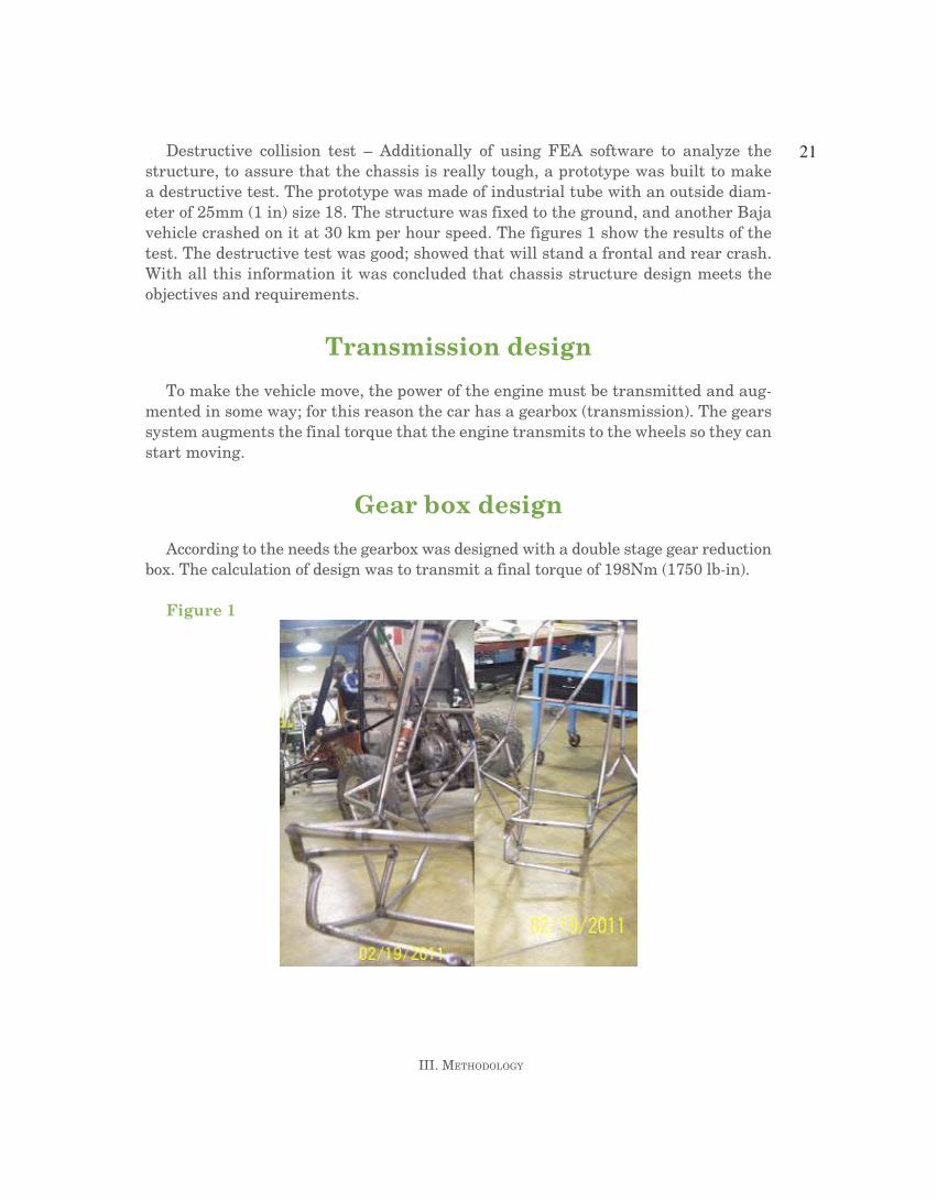
Destructive collision test – Additionally of using FEA software to analyze the structure, to assure that the chassis is really tough, a prototype was built to make a destructive test. The prototype was made of industrial tube with an outside diam-eter of 25mm (1 in) size 18. The structure was fixed to the ground, and another baja vehicle crashed on it at 30 km per hour speed. The figures 1 show the results of the test. The destructive test was good; showed that will stand a frontal and rear crash. With all this information it was concluded that chassis structure design meets the objectives and requirements.
Transmission design
To make the vehicle move, the power of the engine must be transmitted and aug-mented in some way; for this reason the car has a gearbox (transmission). The gears system augments the final torque that the engine transmits to the wheels so they can start moving.
Gear box design
According to the needs the gearbox was designed with a double stage gear reduction box. The calculation of design was to transmit a final torque of 198nm (1750 lb-in).
Figure 1

22
Diseño de vehículo Baja sae iii. MethoDology
Gear and shaft specifications - These are the characteristics of the four spur gears of the transmission uses: for the first reduction it has a 19 teeth gear and a 57 teeth gear with a diametrical pitch of 12, both of them with 12.5mm (0.5 in) of face width, and for the second reduction it counts with a 18 teeth gear and a 45 teeth gear with diametrical pitch of 8, both with 18.75mm (0.75mm) of face width. These gears give a first stage reduction of 3:1, and a second reduction of 2.5:1, multiplying this values we have a final reduction of 7.5:1. In addition, the shafts were designed to support all the stresses to which they are subjected, the entrance and the intermediate shafts have an outer diameter of 23.44mm (15/16 in), and the final shaft has 29.69 mm (1 3/16 in). For both gears and shaft is used a 4140 steel which is appropriate for this application.
Covers design - The covers of the gearbox were designed to have an easy and quick assembly, to be strong enough to support all the loads on them, and to be as light as possible. The material used on the covers is aluminum 6061; this is kind of tough but at the same time is light, so is option for the design and manufacturing.
Drive system: cvt (continuous variable transmission)
The revolutions of the engine must be transferred to the wheels somehow and part of that function is done by the CVT. The CVT is a transmission that can change ef-fectively trough an infinite number of gear ratios between maximum and minimum values (called shift ratios).
For this vehicle it was use a Polaris P90 that transfers engine torque and maxi-mize the rpm that are delivered to the gearbox.
Part of the innovation for this year was to modify the edge through a small cut to reduce weight while increasing the speed at which RPM increases these with the intention get better results on the back shifting of the CVT under certain conditions. Flyweight’s average weight is 82.5gr Figure 2 shows the flyweights and spring.
Figure 2

Diseño de vehículo Baja sae
23
iii. MethoDology
Steering design
One of the key systems is the steering system of an automobile as a set of mecha-nisms that are responsible for guiding the front wheels for the vehicle to take the desired path; these mechanisms over time have been improved to achieve three main things for a management system, such as security, softness and precision.
Taking into account these needs the design was done in conjunction with the front suspension system due to the great relationship they have with each other and thus be more efficient when they are manufactured, another point of the system is the prin-ciple that was based, called the Principle of Ackerman or Ackerman geometry. Which is used in the design of steering systems on all vehicles in series or competition.
Rack and pinion
The Rack and Pinion that will be used has the following description, for a more comfortable driving wheel is used a diameter 10 in. This will add one item to the er-gonomics of the vehicle, high efficiency, accuracy and greater control in both straight and curves whether open or closed. Figure 3 Rack and Pinion steering. Specifications – 5/8-36 Spline Stub, 15 in Center to Center (Adjustable), 1/2 bolt holes.
Brake system
For the new design it’s very important to have an optimum braking system. To make that, the team used formulas to calculate the distance, the time and the force necessary to stop the prototype.
Figure 3
According with the rules of this year, and the help of the team’s last year expe-rience, it was decided to use a CnC dual cylinder brake pedal with reverse swing mount of 3/4in pistons, that features an adjustable balance bar for front and rear. The decision it’s the best ergonomic option for the pilot’s comfort. Figure 4.

24
Diseño de vehículo Baja sae iii. MethoDology
Physical considerations
According to the summary of moments in the front tire of the vehicle normal force on the front rim is 1366 newtons and normal force in the rear wheel is 884.67 nek-tons. For the calculations, consider the mass of drivers = 69.5Kg and vehicle mass = 229.5kg. Total mass = 299 Kg. According to the calculations the strength to stop the vehicle equals (mass) (deceleration) = (299Kg)(4.905m) = 1466.5 newtons.
The bRP stainless steel brake lines of 1/8in were chosen to resist the 12MPa pres-sure that offers the master cylinder. The two piston bRP calipers were the best op-tion to fit in the new design. With a force of 7Kn, the piston pushes the brake pads against the rotor, making a uniform brake. Considering the magnitudes of the force, the material has to be such as resistant as the force applied in each part of the sys-tem. In short was needed a force of 1466.5n to stop the vehicle and have a force of 7000n as the vehicle stops whatever the condition of the floor.
Figure 4
Suspension design
The suspension is one of the most important things in a car, it helps in every way, if well design it could make the car overcome any obstacle on the road. basically it is made up of a rigid structure with shocks and springs.
DESIGn.- Once the purpose is taken, it is time to design the suspension according to the needs. The suspension should be enough short to make the car light but still strong to make a 12 inches travel.
With this sketch at hand every change made could be seen in the overall move-ment of the tires.

Diseño de vehículo Baja sae
25
iii. MethoDology
The objectives of this suspension are:
The most ground clearance. ɶA good position of front tires when steer. ɶA 12 inches travel in front suspension ɶ
The ground clearance was obtain with a front suspension of double A arm, hav-ing the lower A arm almost horizontally, making the size of the tire the height of the front part of the vehicle. Suspension geometry affects steering, that was solve having the front tires tilt depending to the turn so that the tires could dig the ground and force the car to turn. All without sacrificing the long travel of the tire.
The front suspension has a 8º of caster and 5º of kingpin. The caster angle was determined by having the tire tilt to the turn side, and the kingpin angle for reducing the tire horizontal drag when moving vertically without restricting steering. The rear suspension is a swing arm, which it restricts the rear tires movement by only vertical displacement, which means 0º camber and it helps for a better traction. The limits of the rear suspension are the continuous variable joints, because their length will determine the width and frame will put the base for it, giving the length required.
Manufacturing
The manufacturing process for the vehicle was based in three main processes. MIG welding process, manual milling and turning process and milling CnC and EDM for key components. Parts design was based in cad/cam/cae software to develop parts and process them in our manufacturing systems laboratory. During the process key steps were considered to assure the quality and functionally of the assemblies. One key step was to make additional prototype parts to get experience mainly on weld-ing.

27
iv. results
As was mentioned in the project objectives, which are the following:
Improve performance by design a new gearbox. ɶReduce vehicle weight. ɶDesign a new suspension system. ɶDesign a new steering system to improve maneuverability. ɶ
The vehicle was improved in overall on each of these goals. During the process of testing and validating these goals were met.
During test brake was better, cornering was much better than expected. In the other hand the gearbox was slim and lighter as planned. However, still some work was needed on suspension. It failed during some to rough terrain. The steering sys-tem was also giving good performance during testing.
The vehicle was improved in suspension. During testing better corning was better that previous version.


29
v. conclusions
The project was concentrated in one of the principal goals, to reduce weight. In every system was made a reduction of weight without sacrificing the performance of the new vehicle. There were several improvements including, a better CVT Shifting, Suspension and Steering.
Also the results obtained during testing and competition allowed to evaluated fur-thermore the design improvements areas, in order to enhance vehicle performance.


31
reFerences
1. 2011 baja SAE Competition Rules 2. MOTT, Robert L. Machine elements in mechanical design. Fourth edition. 2006. 3. Miliken, William F., Milliken, Douglas L. Race car vehicle dynamics I. 1995. 4. Miliken, William F., Milliken, Douglas L. Race car vehicle dynamics II. 1995. 5. Indios baja SAE Design report. 2011.
