dfig wind turbine modeling - shoutwiki blog | …images.shoutwiki.com/mindworks/c/c0/2014dfig...dfig...
TRANSCRIPT

DFIG Wind Turbine
Modeling
Team Power Team
Drew McKinnon
Cody Swisher
Tiras Newman
Andy Miles
Student
Mentors: Mike Beacham
Alaap Anujan
Professors:
Dr. Herbert Hess
Dr. Brian Johnson
Dr. Feng Li
Sponsor: SEL
Dr. Normann Fishcher
Presentation Includes:
Introduction to type I, type II and type
III wind turbine generators (WTGs)
Students’ Type III WTG control system
scheme
Students’ Physical DFIG model

Presentation Includes:
Software model of WTG fed power
system
Current standing
Future work

Type I WTG
• Squirrel-cage induction generator
• Connected to transmission step-up transformer
directly
• Turbine speed is fixed (or nearly fixed) to grid
frequency
• Generates real power when turbine shaft rotates
faster than the electrical grid frequency
• Low-cost, reliable

Type II WTG
• Wound rotor induction generator
• Also connected to transmission step-up transformer
directly, but includes variable resistance in rotor
circuit
• Can produce power at higher wind speeds than Type I
WTGs

Type III WTG
•Variable frequency AC rotor excitation
•Current regulated voltage-source converter
•Immediate adjustment of rotor current’s
magnitude and phase
•Exchanges power via back-to-back AC-DC
converters

Type III WTG
•Small adjustments to rotor circuit have large
effect on stator circuit
•Can operate with wind speeds+/- 50% of
synchronous speed

Type III WTG
•Separate real and reactive power controls while
running asynchronously
•More expensive than Type I and II WTG due to
power electronics controls
•Type III WTGs behave like a controlled current
source during faults

WTG Type Comparison
Type I Type II Type III
Machine Used Squirrel Cage
Induction
Generator
Wound Rotor
Induction
Generator
Doubly-Fed
Induction
Generator
Wind Speed
Control
2-3 % 10 % 50 %
Separate
Real/Reactive
Power Control
No No Yes
Cost Lowest cost Mid to low cost High cost

Behavior During
Faults
Type I and II WTGs behave similar to large
induction machines, producing fault currents
of 5-6 pu
Faults are usually easily detected

Behavior During
Faults
Faults on Type III WTG typically produce
fault currents of 1.1-2.5 pu
Faults are difficult to protect without
nuisance tripping
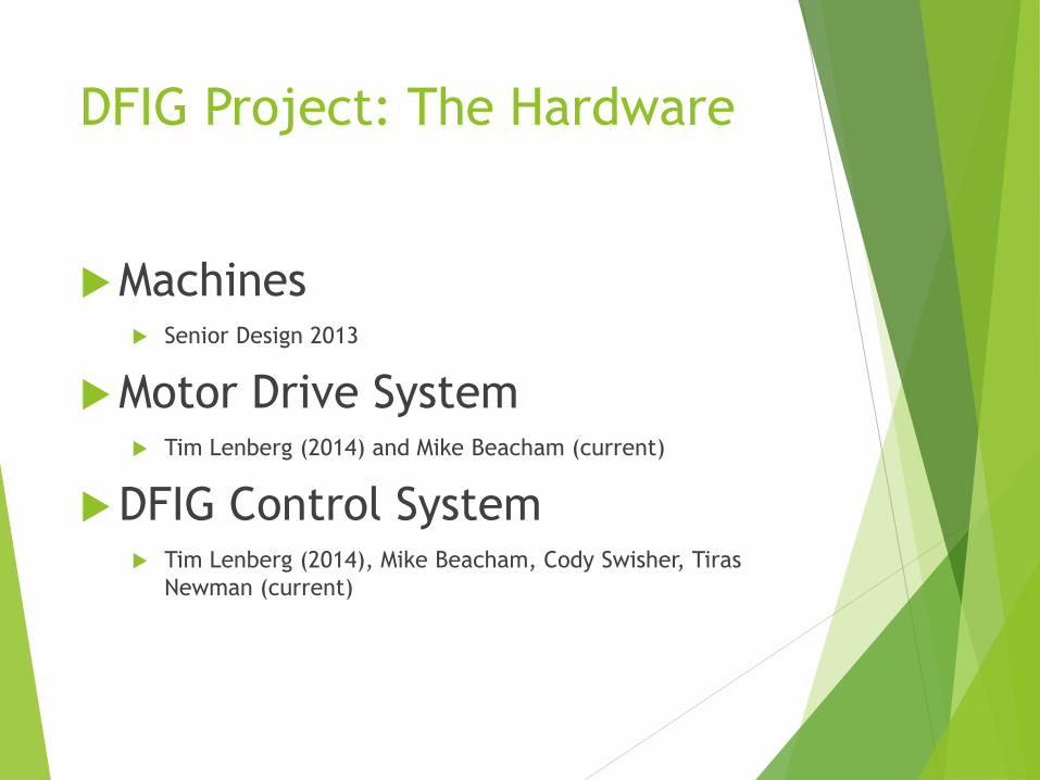
DFIG Project: The Hardware
Machines Senior Design 2013
Motor Drive System Tim Lenberg (2014) and Mike Beacham (current)
DFIG Control System Tim Lenberg (2014), Mike Beacham, Cody Swisher, Tiras
Newman (current)

ABB Drive
System
IGBT Drive
system
Squirrel Cage
Induction
Machine
(SCIM)
Doubly Fed
Induction
Machine (DFIG)
The Hardware:

IGBT Drive (Insulated Gate Bipolar Transistor)
Rotor
Stator IGBT
IGBT
Measurements
and protection Enerpro Firing
Board
Microchip Controller
Grid Voltage

Controller: Work in progress
Microchip PIC24 microcontroller
Programmed in C language
Gathers data
Synchronous (dq0) reference frame calculation
Sends firing signals to Enerpro device
MATLAB Model
Simulink Block Diagram
Similar to what we needed
Modification currently underway

Simulink Control System
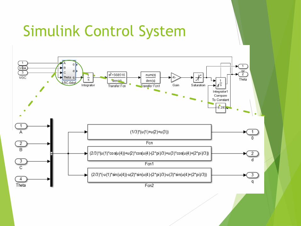
Simulink Control System

Park Transform
Transforms rotating A, B and C phases into a two-axis
(dq) reference frame (vectors)

Simulation Model

RTDS
(Real Time Digital Simulator)
The simulator operates in REAL TIME
Closed Loop Testing
For Protective Relays
Power System Models
Fault Simulations
Other Loop Studies

The RTDS

DFIG: Parametarization of DFIG
Short circuit, open circuit, locked
rotor tests
DFIG Equivalent Circuit

RSCAD Model (Originally by Rishabh Jain)

System

VSC

DFIG – 33kV system

345kV system

Steady State Simulations

A-Ground Fault Simulations

Where the Project Stands
RSCAD Model is now finished and
providing expected results
690V
208V
Control scheme currently in initial phases
Park’s transformation being coded into
microcontroller

What’s Next
Implement and verify controls
Test DFIG on Model Power System
Compare physical DFIG to RSCAD simulation