dewatering of fuel tank
TRANSCRIPT

8/13/2019 Dewatering of Fuel Tank
http://slidepdf.com/reader/full/dewatering-of-fuel-tank 1/5
.jE
^FJ argr-adl nllgl ; o I t, LuJl 9 l+rd asle F\.nesmo & olfodl controcting co.,lld. "\#
METHOD STATEMEI\T
DEwATERING oF F.LIEL TAN?JAND HV CoMPoI.IND SHAFT
SERVICE COMPOLIND
FACILITY 8
MS 8007
1.0 SCOPE
The following proposals focus upon the methodology of dewatering the fuel
storage tanks and HV compound shaft beside the service compound.
2.0
2.1
OUTLINE
The water table in the area of Facility 08
*1.9 but found to occur at approx + 1.0
approx. +3.2 l3.l
was understood to be at approx.
locally. Existing ground level is
2.2 The bottom of excavation of the Fuel tanks is at approx.- 0.9 to - 0.8
7.3 It is proposed to circumferentiate the excavation and reduce the water tablewithinto approx. -3.0 i.e. fall of approx. 1.9 + 3.0 : 4.9m
2.1 Ground water will be removed by a well point and collection sysrempumped away via a piped system to outfall into a storm ditch located
200 m from the access road to the site'.
and be
approx.
2.5 Sketch AYP/JUB/08/C/SK-013 shows the dewatering system for the FuelTanks.
2.6 Sketch AYP/JUB/09/C/SK-006 Rev. C shows the outfall roure from rhedewatering area to the outfall in the storm ditch beside the existing tarmacedNaval base access road. This route was used for dewatering Facility 09.
8/13/2019 Dewatering of Fuel Tank
http://slidepdf.com/reader/full/dewatering-of-fuel-tank 2/5
,ltJ
aa r gr--asJ I ur llgl ; o
I I . binJl g Io,r
r i a-S*tt #\^nesmo & olfodlconlrocting co,,lld. "M
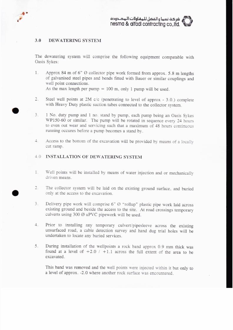
3.0 DEWATERING SYSTEN{
The dewatering system will comprise the following equipment compatable withOasis Sykes:
I. Approx 84 m of 6" A collector pipe work formed from approx. 5.8 m lengthsof galvanised steel pipes and bends fitted with Bauer or similar couplings and
weli point connections.
As the max length per pump : 100 m, only 1 pump will be used.
Steel well points at 2M c/c (penetrating to level of approx - 3.0.) completewith Heavy Duty plastic suction tubes connected to the coliector system.
1 No. duty pump and 1 no. stand by pump, each pump being an oasis S,vkes
wP150-60 or similar. The pump will be rotated in sequence every 24 hoursto even out wear and servicing such that a maximum of 48 hours continuousrunning occures before a pump becomes a stand by.
Access to the bottom of the excavation will be provided by means of a iocallrcut ramp.
')
_1 .
4.0 INSTALLATION OF DEWATERING SYSTEM
l. \trteli points wili be instalied by means of water injection and or mechanicall_v
driven means.
J
The collector system will be iaid on the existin-e ground surface, and buriedonl,v at the access to the excar,ation.
Deiivery pipe work wili comprise 6" o "rollup" plastic pipe work laid acrossexisting ground and beside the access to the site. At road crossings temporaryculverts using 30A g uPVC pipework will be used.
Prior to installing any temporary culvert/pipesleeve across the existingunsurfaced road. a cable detection survey and hand dug trial holes will beundertaken to locate any buried services.
5. During installation of the wellpoints a rock band approx 0.9 mm thick wasfound at a level of +2.0 I +1.1 across the fuil exrent of the area to beexcavated.
This band was removed and the well points u'ere injecred v'ithin it but onlya level of approx. -2.0 where another rock surface \\'as encountered.
-l
1
+.

8/13/2019 Dewatering of Fuel Tank
http://slidepdf.com/reader/full/dewatering-of-fuel-tank 3/5
,il"t'
n3-a rgrcsJ I r-rU gl ;
oI I . lSall q I o,rr r i15 di, rf\^
nesmo & olfodlcontrocfing co.,[d. 'M,
t*,/ /*The dewatering system was made operable. The welipoints vlere removed onewellpoint at a time, excavated locally and replaced in an anti clockwise
rotation.
24 hours after discormecting the flexible
5. REMOVAL OF WELL POINTS
hnWell points willlremoved approx.
coupling from the well head(s).
Well points may be loosened by means ofmechanical extraction in an attempt to minimise
insitu soils.
rejetting and removed byIoss of well points within the

8/13/2019 Dewatering of Fuel Tank
http://slidepdf.com/reader/full/dewatering-of-fuel-tank 4/5
WE
WATER TAN K400 1000
WATTR TANK
EXC.LEVEL = 2.A7
: WATER TANK6
XTG.GL
J. I
50Y_- 2.0
PUMP HOUSIof)r').00
1 .90 rsstlMED
^_:Z__
0.75 APPROX

8/13/2019 Dewatering of Fuel Tank
http://slidepdf.com/reader/full/dewatering-of-fuel-tank 5/5
AB NUC 96'eO'ZZltv r.v
llVC I nnr:r,1"",,
]IV3S I lr.rlod lffi| :6"iloii'o'6tz- ffirlllllI lil l,nI lil ,# l/I tc b
I re'txl F
liI
I nvr
\\ \\
\
L -
ll*ll--_l_1"rrr__| tu l l
I I l- l I
ooeL I lodzi I I_ |l Illl li zs't =
--lLl ll rsnollsl llllol ll
llle lll|P ll
l,'
ltt.llI I I I I zor ='r3^31'3x3I I 1.. I L- 0oqx009x00g
lllE ll)-'-ansJUIr-qffi{o
r ruT------T-------+llllos'rooczp I
I I loI I 18 | oo
f-il--L-I1,1V@
3/t^z
t
ltJ
C] NCIS
t//J'/.=:l: E Al8
ar{xs/t/Yo/rn,/ o^, CN YS
INIUSJYASO ONV NOIIVAV]XSATddOS USJVil ONV CNIJI{3IC AUIJ
::lI]i
TOVJ'IV)g
VI^ISgN
80 AJIIIJY.{ _ III gSVHd USJNOH :rCl lCUd
9Nl0Nl18 uJLlr 9L
a:f 1c uJLu oc
s3d r0
s3d r0
s3d r0
s3d 9e
Sf,d ZI
s3d 9c
s3d 9f
sdvS oNlo,9
lsoHA8l^lll0
ll.lll ..l0 9
dnnd 9NrullvMlcsfy^So ,9
3SV8 NOlI3nS6 B
NOrr3NnllSro B
0Nl8 .06x0 p
s9nld ul88nu
l8nI nnlNlr{n'lv 0 €
ouruJog 38n1 l18lx3'll
CNO'1 l^{9 51Nl0d'1-13/v1
t{flt
[0
MFHIT
ffi' i_J I
-]+l-@
sf.''-I|-Ll l=
lllgUT.
#li* lHL