dewatering and groundwater control · pdf filedewatering and groundwater control. departments...
TRANSCRIPT

This copy is a reprint which includes current ARMY TM 5-818-5NAVY NAVFAC P-418
AIR FORCE AFM 88-5, Chap 6
DEWATERINGAND
GROUNDWATER CONTROL
.
DEPARTMENTS OF THE ARMY, THE NAVY,AND THE AIR FORCENOVEMBER 1983

REPRODUCTION AUlHORlZAllON/RESlRlCllONS
This manual has been prepared by or for the Government and, except to the ex-tent indicated below, is public property and not subject to copyright.
Copyrighted material included in the manual has been used with the knowledgeand permission of the proprietors and is acknowledged as such at point of use.Anyone wishing to make further use of any copyrighted material, by itself andapart from this text, should seek necessary permission directly from the proprie-tors.
Reprints or republications of this manual should include a credit substantially asfollows: “Joint Departments of the Army, the Air Force, and the Navy, USA,Technical Manual TM 5-818-5/AFM 88-5, Chap 6/NAVFAC P-418, Dewateringand Groundwater Control.”
If the reprint or republication includes copyrighted material, the credit shouldalso state: “Anyone wishing to make further use of copyrighted material, by itselfand spurt from this text, should seek necessary permission directly from the pro-prietors.”

TM-8 184AFM 88-5, Chap. 6
NAVFAC P-4 18C - l
Change
No. 1
HEADQUARTERSDEPARTMENTS OF THE ARMY,
AIR FORCE, AND NAVYW ASHINGTON, DC 27 June 1985
DEWATERING AND GROUNDWATER CONTROL
TM %318-5/AFM 88-5, Chapter 6/NAVFAC P-418, 15 November 1983 is changed as follows:1. Remove old pages and insert new pages as indicated below. New or changed material is indicated by a verti-cal bar in the margin of the page.
Remowe pages Insert pqesiandtt . . . . . . . . . . . . . . . . . . . . . . . . . . . . . . . . . . . . . . . . . . . . . . . . . . . . . . . . . . . . . . . . . . . . . . . . . . . . . . . . . . i and iiiA- l ,...,.....,,,,....,.,,........,.......,.................,............................ A- l
2. File this change sheet in front of the publication for reference purposes.
By Order of the Secretaries of the Army, the Air Force, and the Marine Corps:
Officiak
JOHN A. WICKHAM, JR.General, United States Army
Chief of Stag
DONALD J. DELANDROBrigadier General, .?Jnited Stahs Army
The Adjutant General
Official:
EARL T. O’LOUGHLINGeneral, United States Air Force,
Commander, Air ForceLogistics Comm4wh.d
CHARLES A. GABRIELGeneral, United States Air Force
Chief of Stafl
H.A. HATCHLieutenant General, Marine COTQSDeputy Chief of Stiff, Installation
.and Logistics Command


TM 5-8154lAFM 88-5, Chap 6lNAVFACP-418
Figure4-11
4-12
Flow and drawdown for fully and partially penetrating singlewells; circular source; gravity flow
Flow and drawdown for fully penetrating single we& circulars o u r c e ; c o m b i n e d a r t e s i a n a n d g r a v i t y f l o w s
%7e
4-12
4-13
iii Change 1

TM 5-818-5/AFM 88-5, Chap WNAVFAC P-418
CHAPTER 1
INTRODUCTION
l-l. Purpose and scope. This manual providesguidance for the planning, design, supervision, con-struction, and operation of dewatering and pressurerelief systems and of seepage cutoffs for deep excava-tions for structures. It presents: description of variousmethods of dewatering and pressure reliefi techniquesfor determining groundwater conditions, characteris-tics of pervious aquifers, and dewatering require-ments; guidance for specifying requirements for de-watering and seepage control measures; guidance fordetermining the adequacy of designs and plans pre-pared by contractors; procedures for designing, install-ing, operating, and checking the performance of de-watering systems for various types of excavations; anddescriptions and design of various types of cutoffs forcontrolling groundwater.
1-2. General.CL It will generally be the responsibility of the con-
tractor to design, install, and operate dewatering andgroundwater control systems. The principal usefulnessof this manual to design personnel will be those por-tions devoted to selecting and specifying dewateringand groundwater control systems. The portions of themanual dealing with design considerations should fa-cilitate review of the contractor’s plans for achievingthe desired results.
b. Most of the analytical procedures set forth in thismanual for groundwater flow are for “steady-state”flow and not for “unsteady-state” flow, which occursduring the initial phase of dewatering.
c. Some subsurface construction may require de-watering and groundwater control procedures that arenot commonly encountered by construction contract-ors, or the dewatering may be sufficiently critical as toaffect the competency of the foundation and design ofthe substructure. In these cases, it may be desirable todesign and specify the equipment and procedures to beused and to accept responsibility for results obtained.This manual should assist design personnel in thiswork.
1-3. Construction dewatering.a. Need for groundwater control. Proper control of
groundwater can greatly facilitate construction of subsurface structures founded in, or underlain by, per-vious soil strata below the water table by:
(1) Intercepting seepage that would otherwiseemerge from the slopes or bottom of an excavation.
(2) Increasing the stability of excavated slopesand preventing the loss of material from the slopes orbottom of the excavation.
(3) Reducing lateral loads on cofferdams.(4) Eliminating the need for, or reducing, air pres-
sure in tunneling.(5) Improving the excavation and backfill char-
acteristics of sandy soils.Uncontrolled or improperly controlled groundwatercan, by hydrostatic pressure and seepage, cause piping,heave, or reduce the stability of excavation slopes orfoundation soils so as to make them unsuitable for sup-porting the structure. For these reasons, subsurfaceconstruction should not be attempted or permittedwithout appropriate control of the groundwater and(subsurface) hydrostatic pressure.
b. Influence of excavation chunzcteristics. The loca-tion of an excavation, its size, depth, and type, such asopen cut, shaft, or tunnel, and the type of soil to beexcavated are important considerations in the selec-tion and design of a dewatering system. For mostgranular soils, the groundwater table during construc-tion should be maintained at least 2 to 3 feet below theslopes and bottom of an excavation in order to ensure“dry” working conditions. It may need to be main-tained at lower depths for silts (5 to 10 feet below subgrade) to prevent water pumping to the surface andmaking the bottom of the excavation wet and spongy.Where such deep dewatering provisions are necessary,they should be explicitly required by the specificationsas they greatly exceed normal requirements and wouldnot otherwise be anticipated by contractors.
(1) Where the bottom of an excavation is under-lain by a clay, silt, or shale stratum that is underlainby a pervious formation under artesian pressure (fig.l-l), the upward pressure or seepage may rupture thebottom of the excavation or keep it wet even thoughthe slopes have been dewatered. Factor of safety con-siderations with regard to artesian pressure are dis-cussed in paragraph 4-8.
(2) Special measures may be required for excava-tions extending into weathered rock or shale wheresubstantial water inflow can be accommodated with-out severe erosion. If the groundwater has not beencontrolled by dewatering and there is appreciable flow
l - l

TM 5-818-5/AFM 88-5, Chap WNAVFAC P-418
RIVER STAGE PIEZOMETERS
WATER TABLE FROM B0
//
HYDROSTATIC PRESSURE FROM AL- -----1 S A N D
C L A Y
-IMPERVIOUS
B A C K F I L L S A N D
mw
C L A Y O R R O C K
-
(Modified from “Foundation Engineering, ” G. A . ieonards, ed., 1962, McGraw-HiiiBook Company. Used with permission of McGraw-Hill Book Company.)
Figure 1-1. Installation ofpiezometers for determining water tableand artesian hydrostaticpressure.
or significant hydrostatic pressures within the rock orshale deposit, rock anchors, tiebacks, and lagging orbracing may be required to prevent heave or to supportexposed excavation slopes.
(3) An important facet of dewatering an excava-tion is the relative risk of damage that may occur tothe excavation, cofferdam, or foundation for a struc-ture in event of failure of the dewatering system. Themethod of excavation and reuse of the excavated soilmay also have a bearing on the need for dewatering.These factors, as well as the construction schedule,must be determined and evaluated before proceedingwith the design of a dewatering system.
c. Groundwater control methods. Methods for con-trolling groundwater may be divided into three cate-gories:
(1) Interception and removal of groumhvater fromthe site by pumping from sumps, wells, wellpoints, ordrains. This type of control must include conside:rationof a filter to prevent migration of fines and possibledevelopment of piping in the soil being drained.
(2) Reduction of artesian pressure beneath thebottom of an excavation.
(3) Isolation of the excavation from the inflow ofgroundwater by a sheet-pile cutoff, grout curtain,slurry cutoff wall, or by freezing.
1-4. Permanent groundwater control.Many factors relating to the design of a temporary de-watering or pressure relief system are equally applica-ble to the design of permanent groundwater controlsystems. The principal differences are the require-ments for permanency and the need for continuousoperation. The requirements for permanent drainagesystems depend largely on the structural design andoperational requirements of the facility. Since perma-nent groundwater control systems must operate con-tinuously without interruption, they should be con-servatively designed and mechanically simple to avoidthe need for complicated control equipment subject tofailure and the need for operating personnel. Perma-nent drainage systems should include provisions forinspection, maintenance, and monitoring the behaviorof the system in more detail than is usually requiredfor construction dewatering systems. Permanent sys-tems should be conservatively designed so that satis-factory results are achieved even if there is a rise inthe groundwater level in the surrounding area, whichmay occur if water supply wells are shut down or if theefficiency of the dewatering system decreases, as mayhappen if bacteria growth develops in the filter sys-tem. An example of a permanent groundwater controlsystem is shown in figure 1-2.
_
1-2

TM 5-818-5/AFM 88-5, Chap 6/NAVFAC P-418
IMPERVIOUS BACKFILL
PERVIOUS BACKFILL
/bIl7-/AL cWATERTABLE Q- .
SIJMP AND PUMP, jpfzn
DISCHAR
S A N D .,*fi. .
GE
ARTESIAN FLOW , l, SAND . l
U.S. Army corps of Engineers(Frum & Associates, Inc.)
Figure 1-2, Permanentgroundwater control system.
1-3

TM 5-818-5/AFM 88-5, Chap WNAVFAC P-418
CHAPTER 2
METHODS FOR DEWATERING, PRESSURE RELIEF,AND SEEPAGE CUTOFF
2-1. General.a. Tempomry dewatering systems. Dewatering and
control of groundwater during construction may be ac-complished by one or a combination of methods de-scribed in the following paragraphs. The applicabilityof different methods to various types of excavations,groundwater lowering, and soil conditions is also dis-cussed in these paragraphs. Analysis and design of de-watering pressure relief and groundwater control sys-tems are described in chapter 4.
b. Permanent dminuge systems. The principles andmethods of groundwater control for permanent struc-tures are similar to those to be described for construc-tion projects. A method often used for permanentgroundwater control consists of relief wells (to be dis-cussed subsequently in detail) installed beneath andadjacent to the structure, with drainage blankets be-neath and surrounding the structure at locations belowthe water table as shown previously in figure 1-2. Thewater entering the wells and drainage blanket iscarried through collector pipes to sumps, pits, or man-holes, from which it is pumped or drained. Permanentgroundwater control may include a combination ofwells, cutoffs, and vertical sand drains. Additional in-formation on the design of permanent drainage sys-tems for buildings may be found in TM 5-81%l/AFM88-3, Chapter 7; TM 5-818-4/AFM 88-5, Chapter 5;and TM 5-818-6/AFM 88-32. (See app, A for ref-erences.)
2-2. Types and source of seepage.a. Types of seepage flow. Types of seepage flow are
tabulated below:
Type of flow Flow characteristics
Artesian Seepage through the previous aquifer is confinedbetween two or more impervious strata, andthe piezometric head within the previousaquifer is above the top of the pervious aqui-fer (fig. 1-2).
Gravity !l’he surface of the water table is below the top ofthe pervious aquifer (fig. 1-2).
For some soil configurations and drawdowns, the flowmay be artesian in some areas and gravity in otherareas, such as near wells or sumps where drawdownoccurs. The type of seepage flow to a dewatering sys-tem can be determined from a study of the ground-
water table and soil formations in the area and thedrawdown required to dewater the excavation.
b. Source of seepage flow. The source and distanceL* to the source of seepage or radius of influence Rmust be estimated or determined prior to designing orevaluating a dewatering or drainage system.
(1) The source of seepage depends on the geo-logical features of the area, the existence of adjacentstreams or bodies of water, the perviousness of thesand formation, recharge, amount of drawdown, andduration of pumping. The source of seepage may be anearby stream or lake, the aquifer being drained, orboth an adjacent body of water and storage in theaquifer.
(2) Where the site is not adjacent to a river orlake, the source of seepage will be from storage in theformation being drained and recharged from rainfallover the area. Where this condition exists, flow to thearea being dewatered can be computed on the assump-tion that the source of seepage is circular and at a dis-tance R. The radius of influence R is defined as theradius of the circle beyond which pumping of a de-watering system has no significant effect on the origi-nal groundwater level or piezometric surface (see para4-2u(3)).
(3) Where an excavation is located close to a riveror shoreline in contact with the aquifer to be de-watered, the distance to the effective source of seepageL, if less than R/2, may be considered as being approxi-mately the near bank of the river; if the distance to theriverbank or shoreline is equal to about Rl2, or greater,the source of seepage can be considered a circle with aradius somewhat less than R.
(4) Where a line or two parallel lines of wells areinstalled in an area not close to a river, the source ofseepage may be considered as a line paralleling the lineof wells.
2-3. Sumps and ditches.a. Open excavations, An elementary dewatering
procedure involves installation of ditches, Frenchdrains, and sumps within an excavation, from whichwater entering the excavation can be pumped (fig.2-1). This method of dewatering generally should not
*For convenience, symbols and unusual abbreviations are hstedin the Notation (app B).
2 - 1

TM 5-818-5/AFM 88-5, Chap 6/NAVFAC P-418
LOWERED WATER TABLESUMP PUMP
(Mod$edfrotn “Foundation Engineering, “G. A. Leonards, ed., 1962, McGraw-Hill BookCompany. Used with permission of McGraw-Hill Book Company.)
Figure 2-1. Dewatering open excavation by ditch and sump,
be considered where the groundwater head must belowered more than a few feet, as seepage into the ex-cavation may impair the stability of excavation slopesor have a detrimental effect on the integrity of thefoundation soils. Filter blankets or drains may be in-cluded in a sump and ditch system to overcome minorraveling and facilitate collection of seepage. Dis-advantages of a sump dewatering system are slownessin drainage of the slopes; potentially wet conditionsduring excavation and backfilling, which may impedeconstruction and adversely affect the subgrade soil;space required in the bottom of the excavation fordrains, ditches, sumps, and pumps; and the frequentlack of workmen who are skilled in the proper con-struction or operation of sumps.
b. Cofferdams. A common method of excavatingbelow the groundwater table in confined areas is todrive wood or steel sheet piling below subgrade ele-vation, install bracing, excavate the earth, and pumpout any seepage that enters the cofferdammed area.
(1) Dewatering a sheeted excavation with sumpsand ditches is subject to the same limitations and seri-ous disadvantages as for open excavations. However,the danger of hydraulic heave in the bottom of an ex-cavation in sand may be reduced where the sheetingcan be driven into an underlying impermeable stra-tum, thereby reducing the seepage into the bottom ofthe excavation.
(2) Excavations below the water table can some-times be successfully made using sheeting and sumppumping, However, the sheeting and bracing must bedesigned for hydrostatic pressures and reduced toesupport caused by upward seepage forces. Coveringthe bottom of the excavation with an inverted sandand gravel filter blanket will facilitate constructionand pumping out seepage water.
2-4. Wellpoint systems. Wellpoint systems area commonly used dewatering method as they are appli-
2-2
cable to a wide range of excavations and groundwaterconditions.
a. Conventional wellpoint systems. A conventionalwellpoint system consists of one or more stages ofwellpoints having 1% or 2-inch-diameter riser pipes,installed in a line or ring at spacings between about 3and 10 feet, with the risers connected to a commonheader pumped with one or more wellpoint pumps.Wellpoints are small well screens composed of eitherbrass or stainless steel mesh, slotted brass or plasticpipe, or trapezoidal-shaped wire wrapped on rods toform a screen. They generally range in size from 2 to 4inches in diameter and 2 to 5 feet in length and areconstructed with either closed ends or self-jetting tipsas shown in figure 2-2. They may or may not be sur-rounded with a filter depending upon the type of soildrained. Wellpoint screens and riser pipes may be aslarge as 6 inches and as long as 25 feet in certain situa-tions. A wellpoint pump uses a combined vacuum anda centrifugal pump connected to the header to producea vacuum in the system and to pump out the waterthat drains to the wellpoints. One or more sup-plementary vacuum pumps may be added to the mainpumps where additional air handling capacity is re-quired or desirable. Generally, a stage of wellpoints(wellpoints connected to a header at a common eleva-tion) is capable of lowering the groundwater tableabout 15 feet; lowering the groundwater more than 15feet generally requires a multistage installation ofwellpoints as shown in figures 2-3 and 2-4. A well-point system% usually the most practical method fordewatering where the site is accessible and where theexcavation and water-bearing strata to be drained arenot too deep. For large or deep excavations where thedepth of excavation is more than 30 or 40 feet, orwhere artesian pressure in a deep aquifer must be re-duced, it may be more practical to use eductor-typewellpoints or deep wells (discussed subsequently) withturbine or submersible pumps, using wellpoints as a
-

TM 5-818-5/AFM 88-5, Chap 6/NAVFAC P-418
Figure 2-2. Self-jetting wellpoint.
2-3

TM 5-818-5/AFM 88-5, Chap 6/NAVFAC P-418
(From “Foundorion Engineering, ” G. A. L,eonords, ed., 1962, McGraw-HillBook Compony. Used with permission of McGraw-Hill Book Compony.)
Figure 2-3. Use of wellpoints where submergence is small
supplementary method of dewatering if needed. Well-points are more suitable than deep wells where thesubmergence available for the well screens is small(fig. 2-3) and close spacing is required to interceptseepage.
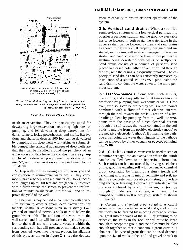
b. Vacuum wellpoint systems. Silts and sandy silts(DXO 5 0.05 ll’ml imetre) with a low coefficient of per-meability (k = 0.1 x 10m4 to 10 x 10m4 centimetresper second) cannot be drained successfully by gravitymethods, but such soils can often be stabilized by auacuum wellpoint system. A vacuum wellpoint systemis essentially a conventional well system in which apartial vacuum is maintained in the sand filter aroundthe wellpoint and riser pipe (fig 2-5). This vacuum willincrease the hydraulic gradient producing flow to thewellpoints and will improve drainage and stabilizationof the surrounding soil. For a wellpoint system, the netvacuum at the wellpoint and in the filter is the vacuumin the header pipe minus the lift or length of the riserpipe. Therefore, relatively little vacuum effect can beobtained with a wellpoint system if the lift is morethan about 15 feet. If there is much air loss, it may benecessary to provide additional vacuum pumps to en-sure maintaining the maximum vacuum in the filtercolumn. The required capacity of the water pump is, ofcourse, small,
c. Jet-eductor wellpoint systems. Another type ofdewatering system is the jet-eductor wellpoint system(fig. 2-6), which consists of an eductor installed in asmall diameter well or a wellpoint screen attached to ajet-eductor installed at the end of double riser pipes, apressure pipe to supply the jet-eductor and anotherpipe for the discharge from the eductor pump. Eductorwellpoints may also be pumped with a pressure pipewithin a larger return pipe. This type of system hasthe advantage over a conventional wellpoint system ofbeing able to lower the water table as much as 100 feetfrom the top of the excavation. Jet-eductor wellpointsare installed in the same manner as conventional well-points, generally with a filter as required by the foun-dation soils. The two riser pipes are connected to sep-arate headers, one to supply water under pressure tothe eductors and the other for return of flow from thewellpoints and eductors (fig. 2-6). Jet-eductor well-point systems are most advantageously used to dewa-ter deep excavations where the volume of water to bepumped is relatively small because of the low permea-bility of the aquifer.
2-5. Deep-well systems.a. Deep wells can be used to dewater pervious sand
or rock formations or to relieve artesian pressure be-
(From “Soils Mechanics in Engineering Praclice, ” by K. Terzoghi and R. B. Peck, 1948,Wiley & Sons, Inc. Used with permission of Wiley & Sons, Inc.)
Figure 2-4. Drainage of an open deep cut by means of a multistage wellpoint system.
2-4
Header ,Atmospheric
press”re
Note: Vocuum in header = 25 ft; vocwmin filter and soil in vicinity of wellpo in t = approximately IO ft.
(From “Foundation Engineering,” G. A. Leonords? ed.,1962, McGraw-Hill Book Company. Used with permission
of McGraw-Hill Book C0mpan.v.)
Figure 2-5. Vacuum wellpoin t system,
neath an excavation. They are particularly suited fordewatering large excavations requiring high rates ofpumping, and for dewatering deep excavations fordams, tunnels, locks, powerhouses, and shafts. Excava-tions and shafts as deep as 300 feet can be dewateredby pumping from deep wells with turbine or submersi-ble pumps. The principal advantages of deep wells arethat they can be installed around the periphery of anexcavation and thus leave the construction area unem-cumbered by dewatering equipment, as shown in fig-ure 2-7, and the excavation can be predrained for itsfull depth.
b. Deep wells for dewatering are similar in type andconstruction to commercial water wells. They com-monly have a screen with a diameter of 6 to 24 incheswith lengths up to 300 feet and are generally installedwith a filter around the screen to prevent the infiltra-tion of foundation materials into the well and to im-prove the yield of the well,
c. Deep wells may be used in conjunction with a vac-uum system to dewater small, deep excavations fortunnels, shafts, or caissons sunk in relatively fine-grained or stratified pervious soils or rock below thegroundwater table. The addition of a vacuum to thewell screen and filter will increase the hydraulic grad-ient to the well and will create a vacuum within thesurrounding soil that will prevent or minimize seepagefrom perched water into the excavation. Installationsof this type, as shown in figure 2-8, require dequate
TM 5-818-5/AFM 88-5, Chap 6/NAVFAC P-418
vacuum capacity to ensure efficient operations of thesystem.
2-6. Vertical sand drains. Where a stratifiedsemipervious stratum with a low vertical permeabilityoverlies a pervious stratum and the groundwater tablehas to be lowered in both strata, the water table in theupper stratum can be lowered by means of sand drainsas shown in figures 2-9. If properly designed and in-stalled, sand drains will intercept seepage in the upperstratum and conduct it into the lower, more permeablestratum being dewatered with wells or wellpoints.Sand drains consist of a column of pervious sandplaced in a cased hole, either driven or drilled throughthe soil, with the casing subsequently removed. The ca-pacity of sand drains can be significantly increased byinstallation of a slotted 1% or 24nch pipe inside thesand drain to conduct the water down to the more per-vious stratum.
2-7. Electro-osmosis. Some soils, such as silts,clayey silts, and clayey silty sands, at times cannot bedewatered by pumping from wellpoints or wells. How-ever, such soils can be drained by wells or wellpointscombined with a flow of direct electric currentthrough the soil toward the wells. Creation of a hy-draulic gradient by pumping from the wells or well-points with the passage of direct electrical currentthrough the soil causes the water contained in the soilvoids to migrate from the positive electrode (anode) tothe negative electrode (cathode). By making the cath-ode a wellpoint, the water that migrates to the cathodecan be removed by either vacuum or eductor pumping(fig. 2-10).
2-8. Cutoffs. Cutoff curtains can be used to stop orminimize seepage into an excavation where the cutoffcan be installed down to an impervious formation.Such cutoffs can be constructed by driving steel sheetpiling, grouting existing soil with cement or chemicalgrout, excavating by means of a slurry trench andbackfilling with a plastic mix of bentonite and soil, in-stalling a concrete wall, possibly consisting of overlap-ping shafts, or freezing, However, groundwater withinthe area enclosed by a cutoff curtain, or leat..;gethrough or under such a curtain, will have to bepumped out with a well or wellpoint system as shownin figue 2-11.
u. Cement and chemical grout curtains. A cutoffaround an excavation in coarse sand and gravel or por-ous rock can be created by injecting cement or chem-ical grout into the voids of the soil. For grouting to beeffective, the voids in the rock or soil must be largeenough to accept the grout, and the holes must be closeenough together so that a continuous grout curtain isobtained. The type of grout that can be used dependsupon the size of voids in the sand and gravel or rock to
2-5

TM 5-818-5/AFM 88-5, Chap 6DJAVFAC P-418
STANDEY P U M P
PRESSURE PUMP
P R E S S U R E H E A D E R
R E T U R N H E A D E R
a. PLAN
P R E S S U R E P U M P ,
S T A N D B Y P U M P
.
.SAND ~ ’
2.;.’ .
b. SECTION
RE .URN PRESSURE 15 PSI
P R E S S U R E L I N E R E T U R N L I N E100-150 PSI 10-15 PSI
l-I/Z” R I S E R P I P E
1 ” RISER PIPE
e l-l/Z” W E L L P O I N T
PRESSURE PI
VACUUM UP TO 25”
c. TYPICAL EDUCTOR WELLPOINT
U.S Army Corps of Engineers
PE
Figure 2-6. Jet-eductor wellpoint system for dewateringa shaft.
2-6

TM 5-818-5/AFM 88-5, Chap WNAVFAC p-418
Ic E X C A V A T I O N
/ C O N S T R U C T I O N) PIEZOMETER
.v*-:-.. I
; ‘., 0
.
S A N D.
U.S. Army Corps of Engineers
Figure 2-7. Deep-well system for dewateringan excavation in sand.
be grouted. Grouts commonly used for this purpose areportland cement and water; cement, bentonite, an ad-mixture to reduce surface tension, and water; silicagels; or a commercial product. Generally, grouting offine or medium sand is not very effective for blockingseepage. Single lines of grout holes are also generallyineffective as seepage cutoffs; three or more lines aregenerally required Detailed information on chemicalgrouting and grouting methods is contained in TM5-818-6/AFM 88-32 and NAVFAC DM 7.3.
b. Slurry wak A cutoff to prevent or minimizeseepage into an excavation can also be formed by dig-ging a narrow trench around the area to be excavatedand backfilling it with an impervious soil. Such atrench can be constructed in almost any soil, eitherabove or below the water table, by keeping the trenchfilled with a bentonite mud slurry and backfilling itwith a suitable impervious soil. Generally, the trenchis backfilled with a well-graded clayey sand gravelmixed with bentonite slurry. Details regarding designand construction of a slurry cutoff wall are given inparagraphs 4-9g(2) and 5-5b.
c. Concrete walls. Techniques have been developedfor constructing concrete cutoff walls by overlappingcylinders and also as continuous walls excavated and
concreted in sections. These walls can be reinforcedand are sometimes incorporated as a permanent partof a structure.
d. Steel sheet piling. The effectiveness of sheet pil-ing driven around an excavation to reduce seepage de-pends upon the perviousness of the soil, the tightnessof the interlocks, and the length of the seepage path.Some seepage through the interlocks should be expect-ed. When constructing small structures in open water,it may be desirable to drive steel sheet piling aroundthe structure, excavate the soil underwater, and thentremie in a concrete seal. The concrete tremie sealmust withstand uplift pressures, or pressure reliefmeasures must be used. In restricted areas, it may benecessary to use a combination of sheeting and bracingwith wells or wellpoints installed just inside or outsideof the sheeting. Sheet piling is not very effective inblocking seepage where boulders or other hard obstructions may be encountered because of driving outof interlock.
e. Freezing. Seepage into a excavation or shaft canbe prevented by freezing the surrounding soil. How-ever, freezing is expensive and requires expert design,installation, and operation. If the soil around the exca-vation is not completely frozen, seepage can cause rap-
2-7

TM 5-818-5/AFM 88-5, Chap WNAVFAC P-418
L’ACUUM PUMP
DISCHARGE
U.S. Army Corps of Engineers
Figure 2-8. Deep wells with auxiliary vacuum system for dewateringa shxzft in stratified materiak.
id enlargement of a fault (unfrozen zone) with conse-quent serious trouble, which is difficult to remedy.
2-10. Selection of dewatering system.a. General. The method most suitable for dewater-
ing an excavation depends upon the location, type,2-9. Summary of groundwater control size, and depth of the excavation; thickness, stratifica-methods. A brief summary of groundwater control tion, and permeability of the foundation soils belowmethods discussed in this section is given in table 2- 1. the water table into which the excavation extends or is
2-8

TM 5-818-S/AFM 88-5, Chap WNAVFAC p-418
GROUNDWATER TABLEDUE TO SAND D R A I N S
AVERAGE HEAD AT LINE OFSAND DRAINS DUE TO PUMPINGWELLS OR WELLPOINTS
.ORlGlNAL
G R O U N D W A T E R
TABLE IN S ILT
Figure 2-9. Sand dmins for dewatering a slope.
underlain; potential damage resulting from failure of (3) Labor requirements.the dewatering system; and the cost of installation and (4) Duration of required pumping.operation of the system. The cost of a dewatering The rapid development of slurry cutoff walls has mademethod or system will depend upon: this method of groundwater control, combined with a
(1) Type, size, and pumping requirements of proj- certain amount of pumping, a practical and econom-ect. ical alternative for some projects, especially those
(2) Type and availability of power. where pumping costs would otherwise be great.
/ C A T H O D E W E L L P O I N T
WELLPOI N T P U M P
W E L L P O I N T/ A N O D E P R O B E
SECTI ON A-A
U.S. Army Corps of Engineers
P L A N
W E L L P O I N T
H E A D E R 2
SECTION B-B
B. -t
Figure 2-10. Electro-osmotic wellpoint system for stabilizing an excuuution slope.
2-9

TM 5-818-5/AFM 88-5, Chap 6/NAVFAC P-418
--
LGROUT C U R T A I N O R fC U T O F F T R E N C H GROUT CURTAIN OR
CUTOFF TRENCH
U.S. Army Corps of Engineers
Figure 2-1 I. Grout curtain or cutoff trench around an excavation.
b. Factors controlling selection. Where foundationsmust be constructed on soils below the groundwaterlevel, it will generally be necessary to dewater the ex-cavation by means of a deep-well or wellpoint systemrather than trenching and sump pumping, Dewateringis usually essential to prevent damage to foundationsoils caused by equipment operations and sloughing orsliding in of the side slopes. Conventional deep-welland wellpoint systems designed and installed by com-panies specializing in this work are generally satisfac-tory, and detailed designs need not be prepared by theengineer. However, where unusual pressure relief ordewatering requirements must be achieved, the engi-neer should make detailed analyses and specify the de-watering system or detailed results to be achieved inthe contract documents. Where unusual equipmentand procedures are required to achieve desired results,they should be described in detail in the contract docu-ments. The user of this manual is referred toparagraphs 6b, 14b, and 2f of Appendix III, TM5-818-4lAFM 88-5, Chapter 5, for additional discus-sions of dewatering requirements and contract speci-fications. Major factors affecting selection of dewater-ing and groundwater control systems are discussed inthe following paragraphs.
(1) Type of excu uu tion. Small open excavations, orexcavations where the depth of water table lowering issmall, can generally be dewatering most economicallyand safely by means of a conventional wellpoint sys-tem. If the excavation requires that the water table orartesian pressure be lowered more than 20 or 30 feet, asystem of jet-eductor type wellpoints or deep wellsmay be more suitable. Either wellpoints, deep wells, ora combination thereof can be used to dewater an exca-
2-10
vation surrounded by a cofferdam. Excavations fordeep shafts, caissons, or tunnels that penetrate strati-fied pervious soil or rock can generally best be dewa-tered with either a deep-well system (with or withoutan auxiliary vacuum) or a jet-eductor wellpoint systemdepending on the soil formation and required rate ofpumping, but slurry cutoff walls and freezing shouldbe evaluated as alternative procedures. Other factorsrelating to selection of a dewatering system are inter-ference of the system with construction operations,space available for the system, sequence of construc-tion operations, durations of dewatering, and cost ofthe installation and its operation. Where groundwaterlowering is expensive and where cofferdams are re-quired, caisson construction may be more economical.Caissons are being used more frequently, even forsmall structures.
_.
(2) Geologic and soil conditions. The geologic andsoil formations at a site may dictate the type of dewa-tering or drainage system. If the soil below the watertable is a deep, more or less homogeneous, free-drain-ing sand, it can be effectively dewatered with either aconventional well or wellpoint system. If, on the otherhand, the formation is highly stratified, or the saturat-ed soil to be dewatered is underlain by an imperviousstratum of clay, shale, or rock, wellpoints or wells onrelatively close centers may be required. Where soiland groundwater conditions require only the relief ofartesian pressure beneath an excavation, this pressurerelief can be accomplished by means of relatively fewdeep wells or jet-eductor wellpoints installed aroundand at the top of the excavation.
(a) If an aquifer is thick so that the penetrationof a system of wellpoints is small, the small ratio of
-

Tabl
e Z
-I.
Sum
mur
y of
Gro
undw
ater
Con
trol
Met
hods
.
Method
Applicability
Sump
s an
d di
tche
sCollect water entering an excava-
tion or structure. ’
Conventional wellpoint
syst
em
Vacuum wellpoint system
Jet-eductor wellpoint
Deep-well systems
Vertical sand drains
Electroosmosis
cuto
ffs
U. S
. Army Corps of Engineers
Dewater soils that can be drained
by gravity
flow.
Dewa
ter or
sta
bili
ze soi
ls wit
hlow permeability. (Some silts,
sand
y si
lts)
.
Dewater soils that can be drained
by gravity
flow.
Usually for
deep
exc
avat
ions
whe
re sma
llfl
ows
are
requ
ired
.
Dewater soils that can be drained
by gravity
flow.
Usually for
larg
e, dee
p ex
cava
tion
s wh
ere
large
flows
are
required.
Usua
lly us
ed to co
nduc
t wa
ter
from
an up
per st
ratu
m to
alower
more pervious stratum.
Dewa
ter so
ils th
at can
not be
drained
by gravity.
(Som
e si
lts,
clayey silts,
clayey silty sands),
Stop or minimize seepage into an
exca
vati
on whe
n in
stal
led do
wnto
an im
perv
ious
str
atum
.
Rema
rks
Generally water level can be lowered only a few
feet.
Used to collect water within cofferdams and
exca
vati
ons.
Sumping is usually only successful
in rel
ativ
ely st
able
gra
vel or
wel
l-gr
aded
san
dygr
avel
, pa
rtia
lly ce
ment
ed mat
eria
ls, or
por
ous
rock formations.
Most commonly used dewatering method.
Draw
down
limited to about 15 ft per stage; however, several
stages may
be used.
Can
be installed
quickly.
Vacuum increases the hydraulic gradient causing
flow
.Little vacuum effect can be obtained if
lift is more than 15 ft.
Can lo
wer wa
ter ta
ble as
muc
h as
100
ft fr
om top
of excavation.
Jet-
educ
tors are particularly
suitable for dewatering shafts and tunnels. !
t'wo
header pipes and two riser pipes, or a pipe with-
in a pipe,
are required.
Csn be installed around periphery of excavation,
thus removing dewatering equipment from within
the
exca
vati
on.
Deep wells are particularly
suitable for dewatering shafts and tunnels.
Not effective in highly pervious soils.
Direct electrical
current increases hydraulic
grad
ient
cau
sing
flow
.
See paragraph 2-8
for
materials
used.

TM 5-818-5/AFM 88-5, Chap WNAVFAC P-418
screen length to aquifer thickness may result in rela-tively little drawdown within the excavation, eventhough the water table is lowered 15 to 20 feet at theline of wellpoints. For deep aquifers, a deep-well sys-tem will generally be more applicable, or the length ofthe wellpoints should be increased and the wellpointsset deep and surrounded with a high-capacity filter.On the other hand, if the aquifer is relatively thin orstratified wellpoints may be best suited to the situa-tion.
(b) The perviousness and drainability of a soil orrock may dictate the general type of a dewatering sys-tem to be used for a project. A guide for the selectionof a dewatering system related to the grain size of soilsis presented in figure 2-12. Some gravels and rock for-mations may be so permeable that a barrier to flow,such as a slurry trench, grout curtain, sheet pile cutoff,or freezing, may be necessary to reduce the quantity offlow to the dewatering system to reasonable propor-tions. Clean, free-draining sands can be effectively de-watered by wells or wellpoints. Drainage of sandy siltsand silts will usually require the application of addi-tional vacuum to well or wellpoint dewatering sys-tems, or possibly the use of the electroosmotic methodof dewatering where soils are silty or clayey. However,where thin sand layers are present, special require-ments may be unnecessary. Electroosmosis should nev-er be used until a test of a conventional system of well-points, wells with vacuum, or jet-eductor wellpointshas been attempted.
(3) Depth of groundwater lowering. The magni-tude of the drawdown required is an important con-sideration in selecting a dewatering system. If thedrawdown required is large, deep wells or jet-eductorwellpoints may be the best because of their ability toachieve large drawdowns from the top of an excava-tion, whereas many stages of wellpoints would be re-quired to accomplish the same drawdown. Deep wellscan be used for a wide range of flows by selectingpumps of appropriate size, but jet-eductor wellpointsare not as flexible. Since jet-eductor pumps are rela-tively inefficient, they are most applicable where wellflows are small as in silty to fine sand formations.
(4) Reliability requirements. The reliability ofgroundwater control required for a project will have asignificant bearing on the design of the dewateringpumps, power supply, and standby power and equip-ment. If the dewatering problem is one involving therelief of artesian pressure to prevent a “blowup” of thebottom of an excavation, the rate of water table re-bound, in event of failure of the system, may be ex-tremely rapid. Such a situation may influence the typeof pressure relief system selected and require inclusionof standby equipment with automatic power transferand starting equipment.
(5) Required rate of pumping. The rate of pump-
2-12
ing required to dewater an excavation may vary from5 to 50,000 gallons per minute or more. Thus, flow to adrainage system will have an important effect on thedesign and selection of the wells, pumps, and pipingsystem. Turbine or submersible pumps for pumpingdeep wells are available in sizes from 3 to 14 incheswith capacities ranging from 5 to 5000 gallons perminute at heads up to 500 feet. Wellpoint pumps areavailable in sizes from 6 to 12 inches with capacitiesranging from 500 to 5000 gallons per minute depend-ing upon vacuum and discharge heads. Jet-eductorpumps are available that will pump from 3 to 20 gal-lons per minute for lifts up to 100 feet. Where soil con-ditions dictate the use of vacuum or electroosmoticwellpoint systems, the rate of pumpage will be verysmall. The rate of pumpage will depend largely on thedistance to the effective source of seepage, amount ofdrawdown or pressure relief required, and thicknessand perviousness of the aquifer through which theflow is occurring.
(6) Intermittent pumping. Pumping labor costs canoccasionally be materially reduced by pumping a dewa-tering system only one or two shifts per day. Whilethis operation is not generally possible, nor advan-tageous, it can be economical where the dewateredarea is large; subsoils below subgrade elevation aredeep, pervious, and homogeneous; and the pumpingplant is oversize. Where these conditions exist, thepumping system can be operated to produce an abnor-mally large drawdown during one or two shifts. Therecovery during nonpumping shifts raises the ground-water level, but not sufficiently to approach subgradeelevation. This type of pumping plant operationshould be permitted only where adequate piezometershave been installed and are read frequently.
(7) Effect of ground wa ter lowering on adjacentstructures and wells. Lowering the groundwater tableincreases the load on foundation soils below the ori-ginal groundwater table. As most soils consolidateupon application of additional load, structures locatedwithin the radius of influence of a dewatering systemmay settle. The possibility of such settlement shouldbe investigated before a dewatering system is de-signed. Establishing reference hubs on adjacent struc-tures prior to the start of dewatering operations willpermit measuring any settlement that occurs duringdewatering, and provides a warning of possible dis-tress or failure of a structure that might be affected.Recharge of the groundwater, as illustrated in figure2-13, may be necessary to reduce or eliminate distressto adjacent structures, or it may be necessary to usepositive cutoffs to avoid lowering the groundwaterlevel outside of an excavation. Positive cutoffs includesoil freezing and slurry cutoff techniques. Observa-tions should be made of the water level in nearby wellsbefore and during dewatering to determine any effect


TM 5-818-5/AFM 88-5, Chap 6/NAVFAC P-418
DEWATERINGW E L L P O I N T S
R E C H A R G EELLPOINTS
-..
. . . .T A B L E W I T H R E C H A R G E
T A B L E W I T H O U T R E C H A R G E ..
.. . .
L O O S E S I L T Y StN_D
U.S. Army Corps of Engineers
FigureZ-13. Recharge ofgroundwater toprevent settlement of a buildingas a result of dewateringoperations.
of dewatering. This information will provide a basisfor evaluating any claims that may be made.
(8) Dewaterirzg versus cutoffs and other proce-dures. While dewatering is generally the most ex-peditious and economical procedure for controllingwater, it is sometimes possible to excavate more eco-nomically in the wet inside of a cofferdam or caissonand then seal the bottom of the excavation with atremie seal, or use a combination of slurry wall orother type of cutoff and dewatering. Where subsurfaceconstruction extends to a considerable depth or wherehigh uplift pressures or large flows are anticipated, itmay occasionally be advantageous to: substitute acaisson for a conventional foundation and sink it to the
design elevation without lowering the groundwaterlevel; use a combination of’concrete cutoff walls con-structed in slurry-supported trenches, and a tremiedconcrete foundation slab, in which case the cutoffwalls may serve also as part of the completed struc-ture; use large rotary drilling machines for excavatingpurposes, without lowering the groundwater level; oruse freezing techniques. Cofferdams, caissons, and cut-off walls may have difficulty penetrating formationscontaining numerous boulders. Foundation designs re-quiring compressed air will rarely be needed, althoughcompressed air may be economical or necessary forsome tunnel construction work.
2-14

TM 5-818-5/AFM 88-5, Chap WNAVFAC P-418
CHAPTER 3
GEOLOGIC, SOIL, AND GROUNDWATER INVESTIGATIONS
3-1. General. Before selecting or designing a sys- 3-2. Geologic and soil conditions. An un-tern for dewatering an excavation, it is necessary to derstanding of the geology of the area is necessary toconsider or investigate subsurface soils, groundwater plan any investigation of subsurface soil conditions.conditions, power availability, and other factors as Information obtained from the geologic and soil in-listed in table 3-1. The extent and detail of these in- vestigations as outlined in TM 5-818-l/AFM 88-3,vestigations will depend on the effect groundwater Chapter 7 or NAVFAC DM7.1, should he used inand hydrostatic pressure will have on the construction evaluating a dewatering or groundwater control probof the project and the complexity of the dewatering lem. Depending on the completeness of informationproblem. available, it may be possible to postulate the general
Table 3-1. Preliminnry Znuestigations
Item
Geologic and soilconditions
Cr i t i ca l i ty
Groundwater orpiezometricpressurecharacteristics
Investigate Reference
Type, stratif ication, and Para 3-2; TM 5-818-l/thickness of soil involved AFM 88-3, Chapter 7in excavation and NAVFAC DM7.1dewatering
Reliability of power system,damage to excavation orfoundation in event offa i lure , rate of rebound,e tc .
Groundwater table or hydro- Para 2-3 and 3-3static pressure in area andits source. Variation withriver stage, season of year,etc . Type of seepage (arte-
Permeability
Power
Degree of possibleflooding
Sian, gravity, combined).Chemical characteristicsand temperature ofgroundwa ter .
Determine permeability fromvisual , f ield, or labora-tory tests, preferably byf ie ld tests .
Avai labi l i ty , reliabilfty,and capacity of power ats i t e .
Rainfall in area. Runoffcharacteristics. High-water levels in nearbybodies of water.
Para 3-4; Appendix C
Para 3-5
Para 3-6
3-1

TM 5-818-5/AFM 88-5, Chap WNAVFAC P-418
characteristics and stratification of the soil and rockformations in the area. With this information and thesize of and depth of the excavation to be dewatered,the remainder of the geologic and soil investigationscan be planned. Seismic or resistivity surveys (as wellas logged core and soil borings) may be useful in deline-ating the thickness and boundaries of major geologicand soil formations and will often show irregularitiesin the geologic profile that might otherwise go unde-tected (fig. 3-1).
a. Borings.(1) A thorough knowledge of the extent, thick-
ness, stratification, and seepage characteristics of thesubsurface soil or rock adjacent to and beneath an ex-cavation is required to analyze and design a dewater-ing system. These factors are generally determinedduring the normal field exploration that is required formost structures. Samples of the soil or rock formationobtained from these borings should be suitable forclassifying and testing for grain size and permeability,if the complexity of the project warrants. All of the in-formation gathered in the investigation should be pre-sented on soil or geologic profiles of the site. For large,complex dewatering or drainage projects, it may be de-sirable to construct a three-dimensional model of col-ored pegs or transparent plastic to depict the differentgeologic or soil formations at the site.
(2) The depth and spacing of borings (and sam-ples) depend on the character of the materials and onthe type and configuration of the formations or depos-its as discussed in TM 5-818-UAFM 88-3, Chapter 7.Care must be taken that the borings accomplish thefollowing:
S T R U C T U R E
L
(u) Completely penetrate and sample allaquifers that may have a bearing on dewatering an ex-cavation and controlling artesian pressures.
@) Identify (and sample) all soils or rocks thatwould affect or be affected by seepage or hydrostaticpressure.
(c) Delineate the soil stratification.(d) Reveal any significant variation in soil and
rock conditions that would have a bearing on seepageflow, location and depth of wells, or depth of cutoff.Continuous wash or auger boring samples are not con-sidered satisfactory for dewatering exploration as thefines tend to be washed out, thereby changing thecharacter of the soil.
b. Rock coeng. Rock samples, to be meaningful forgroundwater studies, should be intact samples obtained by core’ drilling. Although identification ofrocks can be made from drill cuttings, the determina-tion of characteristics of rock formations, such as fre-quency, orientation, and width of joints or fractures,that affect groundwater flow requires core samples.The percent of core recovery and any voids or loss ofdrill water encountered while core drilling should berecorded. The approximate permeability of rock stratacan be measured by making pressure or pumping testsof the various strata encountered. Without pressure orpumping tests, important details of a rock formationcan remain undetected, even with extensive boringand sampling. For instance, open channels or joints ina rock formation can have a significant influence onthe permeability of the formation, yet core samplesmay not clearly indicate these features where the corerecovery is less than 100 percent,
,RlVER
R O C K
U.S. Army Corps of Engineers
Figure 3-1, Geologic profile developed fromgeophysical explorations,
3-2

TM 5-818-S/AFM 88-5, Chap WNAWAC P-418
c. Soil testing,(1) All soil and rock samples should be carefully
classified, noting particularly those characteristicsthat have a bearing on the perviousness and stratifica-tion of the formation. Soil samples should be classifiedin accordance with the Unified Soil Classification Sys-tem described in MIL-STD-619B. Particular atten-tion should be given to the existence and amount offines (material passing the No. 200 sieve) in sand sam-ples, as such have a pronounced effect on the perme-ability of the sand. Sieve analyses should be made onrepresentative samples of the aquifer sands to deter-mine their gradation and effective grain size D10 . TheD10 size may be used to estimate the coefficient ofpermeabililty k . The gradation is required to designfilters for wells, wellpoints, or permanent drainagesystems to be installed in the formation. Correlationsbetween k and D10 are presented in paragraph 3-4.
(2) Laboratory tests depicted in figure 3-2 can beused to determine the approximate coefficient ofpermeability of a soil or rock sample; however, perme-abilities obtained from such tests may have little rela-tion to field permeability even though conductedunder controlled conditions. When samples of sand aredistributed and repacked, the porosity and orientationof the grains are significantly changed, with resultingmodification of the permeability. Also, any air entrapped in the sand sample during testing will signifi-cantly reduce its permeability. Laboratory tests on
samples of sand that have been segregated or con-taminated with drilling mud during sampling opera-tions do not give reliable results. In addition, thepermeability of remolded samples of sand is usuallyconsiderably less than the horizontal permeability k,,of a formation, which is generally the more significantk factor pertaining to seepage flow to a drainage sys-tem.
(3) Where a nonequilibrium type of pumping test(described in app C) is to be conducted, it is necessaryto estimate the specific yield SY of the formation,which is the volume of water that is free to drain outof a material under natural conditions, in percentageof total volume. It can be determined in the laboratoryby:
(u) Saturating the sample and allowing it todrain. Care must be taken to assure that capillarystresses on the surface of the sample do not cause anincorrect conclusion regarding the drainage.
(b) Estimating SY from the soil type and D10 sizeof the soil and empirical correlations based on fieldand laboratory tests. The specific yield can be com-puted from a drainage test as follows:
SY =IOOVY
VwhereV-< i
volume of water drained from samplegross volume of sample
The specific yield can be estimated from the soil type
haL 0k =-In-
At h(21
(From “Ground Waler Hydrology”by D. K. Todd, 1959, Wi1e.v & Sons,Inc. Used wirh permission of Wile), & Sons, Inc.)
3 - 3
TM 5-818-5/AFM 88-5, Chap 6/NAVFAC P-418
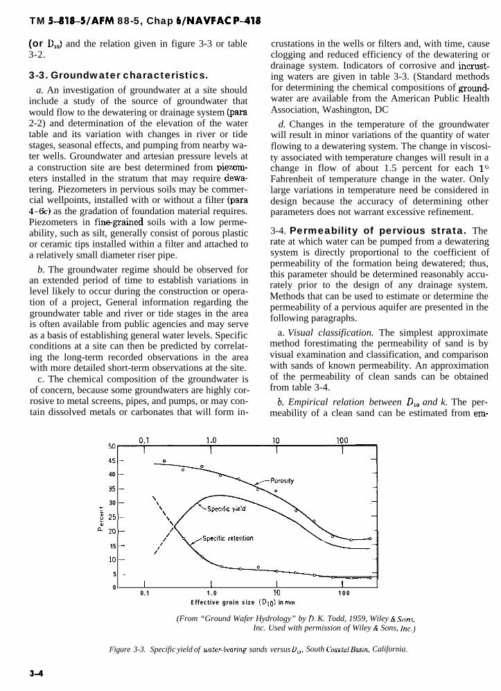
(or DIO) and the relation given in figure 3-3 or table3-2.
3-3. Groundwater characteristics.a. An investigation of groundwater at a site should
include a study of the source of groundwater thatwould flow to the dewatering or drainage system (para2-2) and determination of the elevation of the watertable and its variation with changes in river or tidestages, seasonal effects, and pumping from nearby wa-ter wells. Groundwater and artesian pressure levels ata construction site are best determined from piezom-eters installed in the stratum that may require dewa-tering. Piezometers in pervious soils may be commer-cial wellpoints, installed with or without a filter (para4-6c) as the gradation of foundation material requires.Piezometers in fine-grained soils with a low perme-ability, such as silt, generally consist of porous plasticor ceramic tips installed within a filter and attached toa relatively small diameter riser pipe.
b. The groundwater regime should be observed foran extended period of time to establish variations inlevel likely to occur during the construction or opera-tion of a project, General information regarding thegroundwater table and river or tide stages in the areais often available from public agencies and may serveas a basis of establishing general water levels. Specificconditions at a site can then be predicted by correlat-ing the long-term recorded observations in the areawith more detailed short-term observations at the site.
c. The chemical composition of the groundwater isof concern, because some groundwaters are highly cor-rosive to metal screens, pipes, and pumps, or may con-tain dissolved metals or carbonates that will form in-
crustations in the wells or filters and, with time, causeclogging and reduced efficiency of the dewatering ordrainage system. Indicators of corrosive and incrust- -ing waters are given in table 3-3. (Standard methodsfor determining the chemical compositions of ground-water are available from the American Public HealthAssociation, Washington, DC
d. Changes in the temperature of the groundwaterwill result in minor variations of the quantity of waterflowing to a dewatering system. The change in viscosi-ty associated with temperature changes will result in achange in flow of about 1.5 percent for each loFahrenheit of temperature change in the water. Onlylarge variations in temperature need be considered indesign because the accuracy of determining otherparameters does not warrant excessive refinement.
3-4. Permeability of pervious strata. Therate at which water can be pumped from a dewateringsystem is directly proportional to the coefficient ofpermeability of the formation being dewatered; thus,this parameter should be determined reasonably accu-rately prior to the design of any drainage system.Methods that can be used to estimate or determine thepermeability of a pervious aquifer are presented in thefollowing paragraphs.
a. Visual classification. The simplest approximatemethod forestimating the permeability of sand is byvisual examination and classification, and comparisonwith sands of known permeability. An approximationof the permeability of clean sands can be obtainedfrom table 3-4.
_
b. Empirical relation between DIO and k. The per-meability of a clean sand can be estimated from em-
40 -
35 -
30 -E: 25-z
n 20,-
15 -
IO -
5 -
0 I I I I0 .1 1 . 0 10 1 0 0
E f f e c t i v e g r o i n s i z e (C)IO) in nm
(From “Ground Wafer Hydrology” by D. K. Todd, 1959, Wiley & S0n.s.Inc. Used with permission of Wiley & Sons, k.)
Figure 3-3. Specific yield of wuter-beuring sands versus D,O, South CoastalBusin, California.
3-4

TM 5-818-5/AFM 88-5, Chap 6/NAVFAC P-418
l’dde 3-2, Specific Yieti of Water-Bearing Deposits in Sacramento Valley, California
Material
Specif icYield
percent
Gravel 25
Sand, including sand and gravel, and gravel and sand 20
Fine sand, hard sand, tight sand, sandstone, and relateddeposits 10
Clay and gravel, gravel and clay, cemented gravel, andrelated deposits 5
Clay, silt, sandy clay, lava rock, and related fine-grained deposits 3
(From “Ground Water Hydrology by D. K. Todd, 1959, Wiley & Sons,Inc. Used with permission of Wiley & Sons, Inc.)
Table 3-3. Indicators of Corrosive andIncrusting Waters
Indicators ofCorrosive Water
Indicators ofIncrusting Water
1. A pH less than 7
2. Dissolved oxygen in excess of 2 ppm
3. Hydrogen sulfide (H2S) in excess of
1 ppm, detected by a rotten eggodor
Total dissolved solids in excess of1,000 ppm indicates an ability toconduct electric current greatenough to cause serious electro-lyt ic corrosion
Carbon dioxide (C02) in excess of5 0 ppm
6. Chlorides (Cl) in excess of 500 ppm
1. A pH greater than 7
2. Total iron (Fe) in excessof 2 ppm
3. Total manganese (Mn) inexcess of 1 ppm in con-junction with a high pHand the presence ofoxygen
4. Total carbonate hardnessin excess of 300 ppm
(Courtesy of UOP Johnson Division)
3-5

TM 5-818-5/AFM 88-5, Chap 6/NAVFAC P-418
Table 3-4. Approximate Coefficient of Permeability for Vurious Sands
Type of Sand (UnifiedS o i l C l a s s i f i c a t i o n System)
Sandy siltSilty sandVery fine sandFine sandFine to medium sandMedium sandMedium to coarse sandCoarse sand and gravel
Coef f ic ient o f Permeabi l i ty kx 10 -4 cm/set x -4
10 ft/min
5-20 10-4020-50 40- 10050-200 100-400
200-500 400-1,000500-1,000 l,OOO-2,000
1 ,ooo-1,500 2,000-3,0001,500-2,000 3,000-4,0002,000-5,000 4,000-10,000
U. S. fIrmy Corps of Engineers
pirical relations between DIO and k (fig. 3-4), whichwere developed from laboratory and field pumpingtests for sands in the Mississippi and Arkansas Rivervalleys. An investigation of the permeability of filtersands revealed that the permeability of clean, rela-tively uniform, remolded sand could be estimated fromthe empirical relation:
wherek = C (DJ (3-2)
k = coefficient of permeability, centimetres persecond
C g 100 (may vary from 40 to 150)DIO = effective grain size, centimetres
Empirical relations between DIO and k are o&y upprox-imate and should be used with reservation until a cor-relation based on local experience is available.
c. Field pumping tests. Field pumping tests are themost reliable procedure for determining the in situpermeability of a water-bearing formation. For largedewatering jobs, a pumping test on a well that fullypenetrates the sand stratum to be dewatered is war-ranted; such tests should be made during the designphase so that results can be used for design purposesand will be available for bidders. However, for smalldewatering jobs, it may be more economical to select amore conservative value of k based on empirical rela-tions than to make a field pumping test. Pumping testsare discussed in detail in appendix C.
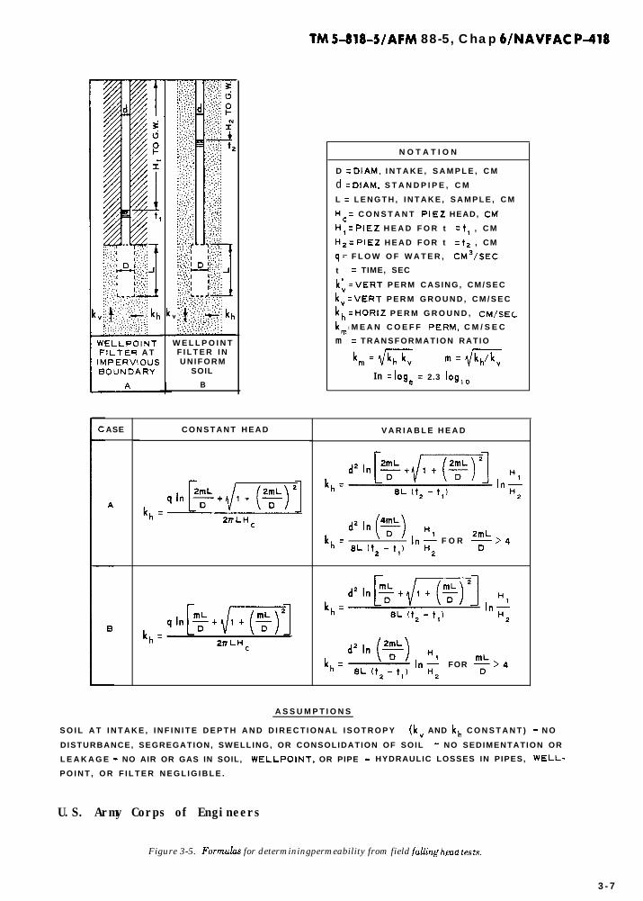
d. Simple field tests in wells or piezometers. Thepermeability of a water-bearing formation can be esti-mated from constant or falling head tests made inwells or piezometers in a manner similar to laboratorypermeameter tests. Figure 3-5 presents formulas fordetermining the permeability using various types andinstallations of well screens. As these tests are sensi-tive to details of the installation and execution of thetest, exact dimensions of the well screen, casing, and
3-6
filter surrounding the well screen, and the rate of in-flow or fall in water level must be accurately meas-ured. Disturbance of the soil adjacent to a borehole orfilter, leakage up the borehole around the casing, clog-ging or removal of the fine-grained particles of theaquifer, or the accumulation of gas bubbles in oraround the well screen can make the test completelyunreliable. Data from such tests must be evaluated
6 100
5% I-D PUMPING2k 50
0.05 0.1 0.2 0.5 1 .o 2.0
EFFEc-rlvE GRAIN S I Z E (Dam) 0~ STRATUM, M M-
Figure 3-4. D,O versus in situ coefficient of korizontalpermeability-Mississippi River valley and Arkansas River valley,
TM 5-818-5/AFM 88-5, Chap 6/NAVFAC P-418
‘ELLPOINT:lLTER A T4PERVlOUS3OUNDARY
ASE C O N S T A N T H E A D
W E L L P O I N TF I L T E R I NU N I F O R M
SOIL
B
N O T A T I O N
D = DIAM, I N T A K E , S A M P L E , C M
d = DIAM, S T A N D P I P E , C M
L = L E N G T H , I N T A K E , S A M P L E , C M
Hc = C O N S T A N T PIE2 HEAD, CM
H, = PIE2 H E A D F O R t = t, , C M
Hz = PIEZ H E A D F O R t = tz , CM
q = F L O W O F W A T E R , CM3/SEC
t = TIME, SEC
k; = VERT P E R M C A S I N G , C M / S E C
kv = VERT P E R M G R O U N D , C M / S E C
k,, = HORIZ P E R M G R O U N D , CM/SEC.
k,,, l M E A N C O E F F PERM, C M / S E C
m = T R A N S F O R M A T I O N R A T I O
4ll=mc m=f/m
I n = loge = 2.3 log,o
V A R I A B L E H E A D
kh =8L It* - t,j
,“; F O R %>4
2
kh = FOR
A S S U M P T I O N S
S O I L A T I N T A K E , I N F I N I T E D E P T H A N D D I R E C T I O N A L I S O T R O P Y (kv AND kh C O N S T A N T ) - N O
DISTURBANCE, SEGREGATION, SWELLING, OR CONSOLIDATION OF SOIL - NO SEDIMENTATION OR
L E A K A G E - NO AIR OR GAS IN SOIL, WELLPOINT, OR PIPE - HYDRAULIC LOSSES IN PIPES, WELL-
P O I N T , O R F I L T E R N E G L I G I B L E .
U.S. Army Corps of Engineers
Figure 3-5. Form&s for determiningpermeability from field falling &au tests,
3 - 7

TM 5-818-5/AFM 88-5, ChaP WNAVFAC P-418
carefully before being used in the design of a major de-watering or drainage system.
3-5. Power. The availability, reliability, andcapacity of power at a site should be investigated priorto selecting or designing the pumping units for a dewa-tering system. Types of power used for dewatering sys-tems include electric, natural gas, butane, diesel, andgasoline engines. Electric motors and diesel enginesare most commonly used to power dewatering equip-ment.
3-6. Surface water. Investigations for the con-trol of surface water at a site should include a study ofprecipitation data for the locality of the project and de-termination of runoff conditions that will exist withinthe excavation. Precipitation data for various localitiesand the frequency of occurrence are available in pub-
lications of the U.S. Weather Bureau or other refer-ence data. Maps showing amounts of rainfall that canbe expected once every 2, 5, and 10 years in lo-, 30-, and 60-minute duration of rainfall are shown in figure3-6. The coefficient of runoff c within the excavationwill depend on the character of soils present or thetreatment, if any, of the slopes. Except for excavationsin clean sands, the coefficient of runoff c is generallyfrom 0.8 to 1.0. The rate of runoff can be determinedas follows:
where
Q=c=
;I
Q = ciA
rate of runoff, cubic feet per secondcoefficient of runoffintensity of rainfall, inches per hourdrainage area, acres
(3-31
(U. S. Department of Agriculture Miscellaneous Publication No. 204)
Figure 3-6. Inches of rainfall during lo- and 30.minute and l-hourperiods.

TM 5-818-5/AFM 88-5, Chap 6/NAVFAC P-418
CHAPTER 4
DESIGN 0~ DEWATERING, PRESSURE RELIEF, ANDGROUNDWATER CONTROL SYSTEMS
4-1. Analysis of groundwater flow.u. Design of a dewatering and pressure relief or
groundwater control system first requires determina-tion of the type of groundwater flow (artesian, gravity,or combined) to be expected and of the type of systemthat will be required. Also, a complete picture of thegroundwater and the subsurface condition is neces-sary. Then the number, size, spacing, and penetrationof wellpoints or wells and the rate at which the watermust be removed to achieve the required groundwaterlowering or pressure relief must be determined.
b. In the analysis of any dewatering system, thesource of seepage must be determined and the bounda-ries and seepage flow characteristics of geologic andsoil formations at and adjacent to the site must be gen-eralized into a form that can be analyzed. In somecases, the dewatering system and soil and groundwa-ter flow conditions can be generalized into rather sim-ple configurations. For example, the source of seepagecan be reduced to a line or circle; the aquifer to a homo-geneous, isotropic formation of uniform thickness; andthe dewatering system to one or two parallel lines orcircle of wells or wellpoints. Analysis of these condi-tions can generally be made by means of mathematicalformulas for flow of groundwater. Complicated con-figurations of wells, sources of seepage, and soil forma-tions can, in most cases, be solved or at least approxi-mated by means of flow nets, electrical analogy mod-els, mathematical formulas, numerical techniques, or acombination of these methods.
c. Any analysis, either mathematical, flow net, orelectrical analogy, is not better than the validity of theformation boundaries and characteristics used in theanalysis. The solution obtained, regardless of the rigoror precision of the analysis, will be representative ofactual behavior only if the problem situation andboundary conditions are adequately represented. Anapproximate solution to the right problem is far moredesirable than a precise solution to the wrong problem.The importance of formulating correct groundwaterflow and boundary conditions, as presented in chapter3, cannot be emphasized too strongly.
d. Methods for dewatering and pressure relief andtheir suitability for various types of excavations andsoil conditions were described in chapter 2. The inves-tigation of factors relating to groundwater flow and to
design of dewatering systems has been discussed inchapter 3. Mathematical, graphical, and electroanalo-gous methods of analyzing seepage flow through gen-eralized soil conditions and boundaries to varioustypes of dewatering or pressure relief systems are pre-sented in paragraphs 4-2,4-3, and 4-4.
e. Other factors that have a bearing on the actualdesign of dewatering, permanent drainage, and sur-face-water control systems are considered in this chap-ter.
f. The formulas and flow net procedures presentedin paragraphs 4-2, 4-3, and 4-4 and figures 4-1through 4-23 are for a steady state of groundwaterflow. During initial stages of dewatering an excava-tion, water is removed from storage and the rate offlow is larger than required to maintain the specifieddrawdown. Therefore, initial pumping rates will prob-ably be about 30 percent larger than computed values.
g. Examples of design for dewatering and pressurerelief systems are given in appendix D.
4-2. Mathematical and model analyses.a. General.
(1) Design. Design of a dewatering system re-quires the determination of the number, size, spacing,and penetration of wells or wellpoints and the rate atwhich water must be removed from the pervious stratato achieve the required groundwater lowering or pres-sure relief. The size and capacity of pumps and collec-tors also depend on the required discharge and draw-down. The fundamental relations between well andwellpoint discharge and corresponding drawdown arepresented in paragraphs 4-2,4-3, and 4-4. The equa-tions presented assume that the flow is laminar, thepervious stratum is homogeneous and isotropic, thewater draining into the system is pumped out at a con-stant rate, and flow conditions have stabilized. Proce-dures for transferring an anisotropic aquifer, with re-spect to permeability, to an isotropic section are pre-sented in appendix E.
(2) Equntions for flow and dmwdown to drainageslots and wells. The equations referenced in para-graphs 4-2,4-3, and 4-4 are in two groups: flow anddrawdown to slots (b below and fig. 4-1 through 4-9)and flow and drawdown to wells (c below and fig. 4-10through 4-22). Equations for slots are applicable to
4-1

TM 5-818-5/AFM 88-5, Chap WNAVFAC P-418
-
Q = y(H - he) (1)
ARTESIAN FLOW
DRAWDOWN
A T A N Y D I S T A N C E y F R O M S L O T
“-h=S(L-y1x
=q(” -he)
u DRAWDOWN
Q =z (Ii* - h;)A T A N Y PISTANCE y F R O M S L O T
Hz _ h2 z q (H* - h;)
GRAVITY FLOW
W H E R E he =ho+ hs A N D hs I S O B T A I N E D
FROM FIG. 4 .2
x DRAWDOWN
kx (D2 -Q =
h;)(zDH - D2 -h;)(51
A T A N Y D I S T A N C E y F R O M S L O T
ZL(D2 -h;)
W H E R E he=ho+hs A N D h
I S O B T A I N E D F R O M *
F IG . 4.2
F O R yzLG H - h =“-// (6)
F O R y g LG H-h=H-[$=$)(y-L‘)+d (7) ---
W H E R E L‘ I S T H E D I S T A N C E F R O M T H E S L O T T O T H E P O I N T
A T W H I C H T H E F L O W C H A N G E S F R O M A R T E S I A N T O
G R A V I T Y , A N D I S C O M P U T E D F R O M
LG =L[D2 - (ho + hs)?
ZDH - D* -(ho + hs)*
COMBINEDARTESIAN-GRAVITY FLOW
(Modlyied from “Foundation Engineering, ” G. A. Leonards, ed., 1962, McGraw-Hill Book Company.Used with permission of McGraw-Hill Book Company.)
Figure 4-1. Flow and head for fully penetrating line slot; single-line source; artesian, gravity, and combined flows,
flow to trenches, French drains, and similar drainagesystems. They may also be used where the drainagesystem consists of closely spaced wells or wellpoints.Assuming a well system equivalent to a slot usuallysimplifies the analysis; however, corrections must bemade to consider that the drainage system consists ofwells or wellpoints rather than the more efficient slot.These corrections are given with the well formulas dis-cussed in c below. When the well system cannot besimulated with a slot, well equations must be used.The figures in which equations for flow to slots andwells appear are indexed in table 4-1. The equations
4-2
for slots and wells do not consider the effects of hy-draulic head losses Hw in wells or wellpoints; proce-dures for accounting for these effects are presentedseparately.
(3) Radius of influence R. Equations for flow todrainage systems from a circular seepage source arebased on the assumption that the system is centeredon an island of radius R. Generally, R is the radius ofinfluence that is defined as the radius of a circle be-yond which pumping of a dewatering system has nosignificant effect on the original groundwater level orpiezometric surface. The value of R can be estimated
‘-

TM 5-818-5/AFM 88-5, Chap 6/NAVFAC P-418
hI 0.6Ii
0 . 4
0 . 2
00 1 2 3 4 5
L
ii
(Modlyied from “Foundalion Engineering, ” G. A. Leonards, ed., 1942, McGraw-HillBook Company. Used wirh permission oj McGraw-Hill Book Company.)
Figure 4-2. Height of free dischnrge surface hs; gmvity flow.
4-3

TM 5-818-5/AFM 88-5, Chap WNAVFAC P-418
FLOW MAX RESIOUAL HEAO OOWNSTREAM OF SLOT
kOx(H - h )Q c
p L+EA(11 ho *
EA(H -he)-+h
LtE e (21A
WHERE E. IS AN ADDITIONAL LENGTH FACTOR OBTAINED FROM THE FIGURE BELOW
(a)
0 6
EA/D b)
ARTESIAN F L O W
(or8pd gro”dvmerIed (“0 pmlp,ng, FLOW MAX RESIDUAL HEAD DOWNSTREAM OF SLOT
m MAX RESIDUAL HEAD DOWNSTREAM OF SLOT+
c = kDx(H - 01p L-Lc (51
II61
P R O V I D E D ho? D, L=? 313
(d)
W H E R E L= = i71
COMBINED ARTESIAN AND GRAVITY FLOWS
(Modzfied from “Foundation Engineering,” G. A. Leonards, ed., 1962, McGraw-HillBook Company. Used wizh permission of McGraw-Hill Book Company.)
Figure 4.3. Flow and head farpartiullypenetrating line slot; single-line source; artes&, gravity, and combined flows.
4-4

TM 5-818-5/AFM 88-5, Chap 6/NAVFAC P418
F U L L Y P E N E T R A T I N G S L O T
T H E F L O W T O A F U L L Y P E N E T R A T I N G S L O T F R O M T W O L I N E S O U R C E S , BPTH O F I N F I N I T E L E N G T H (AND
PARALLEL), I S T H E S U M O F T H E F L O W F R O M E A C H S O U R C E , W I T H R E G A R D T O T H E A P P R O P R I A T E F L O W
B O U N D A R Y C O N D I T I O N S , A S D E T E R M I N E D F R O M T H E F L O W E Q U A T I O N S I N F I G . 4-1. L I K E W I S E , T H E
DRAWDOWN F R O M E A C H S O U R C E C A N B E C O M P U T E D F R O M T H E DRAWDOWN E Q U A T I O N S I N F I G . 4-1 AS IF
O N L Y O N E S O U R C E E X I S T E D .
P A R T I A L L Y P E N E T R A T I N G S L O T
A R T E S I A N F L O W
&.3Dt--1 3Dt:7 y
N O T E : WIDTH OF SLOT, b, A S S U M E 0 = 0.
t WITHIN THIS DISTANCE (1.30) THEP,EZOMElRlC SURFACE IS NONLINEAROUE TO CONVERGING FLOW.
ZkDx(H -he)
Qp=L t AD
F L O W DRAWDOWN
(11
A T A N Y D I S T A N C E y > 1.3D F R O M SL0T.t
(21
t O R A W O O W N WHEN y < 1 .30 CAN EE E S T I M A T E 0 EY ORAWING A FREEHANO C U R V E F R O M he TANGENT ~0 -r”~S L O P E O F T H E LIthEAR PART Al y = 1.3D.
G R AV I T Y F L O W
F L O W
A P P R O X I M A T E L Y , 0UT S O M E W H A T L E S S T H A N , T W I C E T H A T
C O M P U T E D F R O M A S I N G L E S O U R C E , EQ 3, FIG. 4-3.
DRAWDOWN
I---+-4---L-A A P P R O X I M A T E L Y T H A T C O M P U T E D F R O M A S I N G L E S O U R C E ,
(c)EQ 4 , F I G . 4-1.
(hfod$ed from “Foundation Engineering, ” G. A. L,eonards, ed., 1962, McGraw-HillBook Company. Used with permission of McGraw-Hill Book Cornpan),.)
Figure 4-4. Flow and head for fully and part&allypenetrating line slot; two-line source; artesxm and gmvity flows.
4-5

TM 5-818-5/AFM 88-5, Chap WNAVFAC P-416
--
A F R E Q U E N T L Y E N C O U N T E R E D DEWATERING S Y S T E M I S O N E W I T H T W O L I N E S O F P A R T I A L L Y
P E N E T R A T I N G WELLPOINTS A L O N G E A C H S I D E O F A L O N G E X C A V A T I O N , W H E R E T H E F L O W
C A N B E A S S U M E D T O O R I G I N A T E F R O M T W O E Q U I D I S T A N T L I N E S O U R C E S .
F L O W F O R ’ E A C H S L O T C A N B E E S T I M A T E D A S
FORONE S L O T W I T H O N E L I N E S O U R C E , E Q 1s
F I G . 4 - 3 .
V A L U E O F hD C A N B E E S T I M A T E D A S F O R O N E
S L O T A N D O N E LINE S O U R C E , E Q 2 , FIG. 4-3.
A R T E S I A N F L O W
0.8 1,o
C, 0.6 C2
0.4 0.5
0.2
00
02 4 6 8 10 0 0.05 0.10 0,15
h’b, b/H
cc) MIw
F L O W T O E A C H S L O T A P P R O X I M A T E L Y T H A T O N E S L O T W I T H O N E L I N E S O U R C E , E Q 3, F IG . 4 -3 .
- h& t I 1W H E R E C, A N D C2 A R E O B T A I N E D F R O M FIG. CC) A N D td) A B O V E .
G R A V I T Y F L O W
t M A X I M U M R E S I D U A L H E A O M I D W A Y B E T W E E N T H E T W O S L O T S
(Modlyied from “Foundation Engineering,” G. A. Leonards, ed., 1962, McGrabS-HiliBook Company. Used &irh permission of McGraw)-Hill Book Company.)
Figure 4-5, Flow and head (midway) for twopartiallypenetrating slots; two-line source; artesian and gravity flows,
4-6

TM 5-818-5/AFM 88-5, Chap WNAVFAC P-418
S U R F A C EMPING
F L O W 0 O R DRAWDOWN (H - he)C A N B E ESTIMATED ~Rot.3
Qw = (H - he) kD I# 11 I
W H E R E
$= S”APE F A C T O R F O R A R T E S I A N
FLOW O B T A I N E D F R O M CC)
hc CAN B E O B T A I N E D F R O M
P L O T S I N F,G. 4 - 7
tb)
W / D , P E R C E N T
t IF R IS O B T A I N E D F R O M F I G . 4-23, S U B S T I T U T E he F O R hw.
cd
U.S. Army Corps of Engineers
Figure 4-6. Flow and head for fully andpartiullypenetrating circular slots; circular source; artestin flow
from the equation and plots in figure 4-23. Wherethere is little or no recharge to an aquifer, the radius ofinfluence will become greater with pumping time andwith increasecl drawclown in the area being clewaterecl.Generally, R is greater for coarse, very pervious sanclsthai for finer soils. If the value of R is large relative tothe size of the excavation, a reasonably goocl approxi-mation of R will serve aclequately for clesign becauseflow ad clrawclown for such a conclition are not espe-cially sensitive to the actual value of R. As it is usuallyimpossible to cletermine R accurately, the value should
be select-d conservatively from pumping test data or,if necessary, from figure 4-23.
(4) Wetted screen. There should always be suffi-cient well ancl screen length below the requirecl draw-darn in a well in the formation being clewaterecl so thatthe design or requirecl pumping rate does not proclucea gradient at the interface of the formation and thewell filter (or screen) or at the screen ad filter thatstarts to cause the flow to become turbulent. There-fore, the clesign of a clewatering system should alwaysbe checkecl to see that the well or wellpoints have acle-
4-7

TM 5-818-5/AFM 88-5, Chap 6/NAVFAC P-418
I-
(aq - H ) A0 LN3Z&l3d Nl (aq - ‘q) aV3H
(atj - H) 30 .LN3383d Nl (aq - ‘q) ClV3H
U.S. Army Corps of Engineers
--
---
~_.
--
--
~--
--Inm
!n
!GII
<IY
---
--
(aq - H ) 30 LN3ZW3d Nl (=lj - ‘q) ClV3,.,
Figure 4- 7. Head ut center of fully and partinlly penetrating circular slots; circulur source; artesian flow,
4 - 8

TM 5-818-5/AFM 88-5, Chap WNAVFAC p-418
SECTION A-A
FLOW. OT, OR DRAWDOWN, H -he, CAN BE EST1
MATED FROM
OT = (I- - hekD $ I1 I
W,,ERE $ ,S OBTAINED FROM PLOTS SHOWN BELOW
AND PERCENT PENETRATION = W D x 100
NOTE HEAD ALONG LINE A-A WITHIN THE ARRAY,
h D, ,S OBTA!NED FROM FIG 4-9
U.S. Army Corps of Engineers
Figure 4-8. Flow and drawdown at slot for fully andpartiallypenetmting rectangular slots; circuinr source; artesian flow.
quate “wetted screen length hW8” or submergence topass the maximum computed flow. The limiting flowqC into a filter or well screen is approximately equal to
2nrWfi 7.48 gallons per minuteqc =
1.07 ’ per foot of filter (4-1)
or screenwhere
rW = radius of filter or screenk= coefficient of permeability of filter or aquifer
sand, feet per minute
(5) Hydraulic head loss HU. The equations in fig-
ures 4-1 through 4-22 do not consider hydraulic headlosses that occur in the filter, screen, collector pipes,etc. These losses cannot be neglected, however, andmust be accounted for separately. The hydraulic headloss through a filter and screen will depend upon thediameter of the screen, slot width, and opening perfoot of screen, permeability and thickness of the filter;any clogging of the filter or screen by incrustation,drilling fluid, or bacteria; migration of soil or sand par-ticles into the filter; and rate of flow per foot of screen.Graphs for estimating hydraulic head losses in pipes,wells, and screens are shown in figures 4-24 and 4-25.
4-9

TM 5-818-5/AFM 88-5, Chap WNAVFAC P-418
2 t = 0.04, - b =rw
40
1
.z 20-DlM.0FRECT=bxb-
k
2 15 I
:
5a
10
---l---b b- = 0.20, - = i40‘I? ‘W
-DIM. OF RECT = b x b-
t- DIM. O F RECT = b x 2b-j
I- DIM. OF RECT = b x 2b-j k DIM. O F RECT = b x abd
d o . 2 0 Lz*4;re ’ rw
- D I M. O F RECT = b n ab-
N O T E : H E A D , h , ALONG L INE A-A IN F IG . 4:8c! C A N B E O B T A I N E D F R O M C U R V E S A B O V E .
hp = he +‘thp - he)
U.S. Army Corps of Engineers
-.
Figure 4-9. Head within apartinllypenetruting rectangulnr slot; circular source; artesian flow.
4-10

TM 5-818-5/AFM 88-5, Chap WNAVFAC P-d18
HYORA”LlC “EAO LOSS, Hw, IS OBTAINEO 2302
FROM FIG. 4 - 2 4 I?
RADIUS O F INFL”ENCE, R. IS OBTAINEO
F R O M FIG. 4 - 2 3 C
(0)FULLYPENETRATINGWELL
F L O W . Ow
O R
ORAWDOWN, H - h
P A R T I A L L Y P E N E T R A T I N G W E L L
W”ERE G IS E Q U A L T O T H E RAT,0 O F F L O W F R O , . , A P A R T I A L L Y P E N E T R A T I N G W E L L , Owp, T O T H A T F O R A
FIJLLY P E N E T RA T I N G WELL F O R TI.IE SAME DRAWOOWN, H - hw, A T THE PERIPHERY O F TtiE W E L L S .
APPROXIMATEVALUESOF G C A N B E CO,.,P”TED FROMTHE FORM”LA:
M O R E E X A C T V A L U E S C A N B E C O M P U T E D FROMTHEFORM”LA:
G =in R / r _
D
5ii2 Ill = - In
I-(0.675 WiDl I-(0.125 w/o1‘w 1,-I1 - 0.8,s W,D, r(l - 0 . 1 2 5 W,‘Dl- I”$
WHERE r IS THE G A M M A F U N C T I O N ; W =
VAL”ES O F G F O R A T Y P I C A L LARGE-D1
I.000 F T A R E S H O W N IN (b) A B O V E .
DRAWDOWN, H - h
T”ES,,APEOFTHEDRAwDOwNC”R”E IN T H E V I C I N I T Y O F APART,ALLY P E N E T R A T I N G W E L LCA,,b,OT BE D E T E R M I N E D D I R E C -T L Y FRO,.,EQ4BUTCAN BEAPPRDX,,4ATED B Y ASSLIMING T H EE F F E C T O F W E L L P E N E T R A T I O N ,W, ,S I N S I G N I F I C A N T B E Y O N D Av;IS;NzE, I, T H A T I S G R E A T E R
, T H E DRAWDOWN IS AP-PRDXIMATED A S F O L L O W S :
W E L L P E N E T R A T I O N .
AMETER W E L L I,w = 1 . 0 FTI WITH A RADl”S O F I N F L U E N C E O F
1 . C O M P U T E O_p F R O M ECI 4 F O R A G I V E N DRAWDOWN
O F I O N (C).
2 . C O M P U T E l - l - h FROMEQZFORA F”LLY PENE-
TRATING W E L L FOR A D,SCl,ARGE O F O_p I2 O N ICII.
3 . P L O T DRAWDOWN F O R F U L L Y P E N E T R A T I N G W E L L V S
(LOGI, A S S H O W N B Y L I N E A C IN IC).
4 . D R A W A C”R”ED L,NE F R O , . , T”E P O I N T (h_, rw) - P O I N T B IN I L L U S T R A T I O N - F O R THE P A R T I A L L Y P E N E -
T R A T I N G W E L L T O P O I N T A .
T,,E CO,,,B,NED C U R V E , BAC, R E P R E S E N T S A N A P P R O X I M A T I O N O F T!iE DRAWDOWN C U R V E FDR A P A R T I A L L Y
PENETRATING A R T E S I A N W E L L .
(Mod@ed from “Foundation Engineering, ” G. A, Leonards, ed., 1942, McGraw,-Hill Book Company.Used uith permission of McGraul-Hill Book Company.)
Figure 4-10. Flow ana dmwdown for fully and partially penetrating single weUs; circular source; hrte.sian flow.
4 - 1 1

TM 5-818-5/AFM 88-5, Chap WNAVFAC P-418
F U L L Y P E N E T R A T I N G W E L L
FLOW, Q_. O R DRAWDOWN, H2 - hz, N E G L E C T I N G H E I G H T O F F R EE D I S C H A R G E , h’ (C O N D I T IO N (a)).
(1) OR Qw l
trk(t?-h;)
IIT @/rW)
F L O W , Qw, TAKING h’ INTO ACCOUNT tbj CAN BE ESTIMATED ACCURATELY FROM EQ 2 USING
H E I G H T O F W A T E R , t t s (S =0 FOR FULLY PENETRATING WELL) , FOR THE TERM h,.,.
F U L L Y O R P A R T I A L L Y P E N E T R A T I N G W E L L
FLOW, Qw, FOR ANY GRAVITY WELL WITH A CIRCULAR SOURCE
Qw =zrk[(ti - s? - d
,” tR,rwI 1 t (0.30 t >) SIN T]
O R A W D O W N , H - h OR Hz - h’, W H E R E h’ I S A C C O U N T E D F O R ( O B T A I N Q,,, FROM EQ 3)
W H E R E r > l.SH,
W H E R E r < l.SH,
FOR r/h > 1.5,
FOR r/h < 1.5,
F O R 0 . 3 < r / h < 1.5,
FOR r/h < 0.3,
WHERE
A N D
(2)
(3)
.-
(4)
USE’EQ 1
ii-h=Qw P h (lOR/H)
n,kH c, - O..S(s/HI ’ “1(5)
P = 0.13 In R/r (6
p=CxtAc (71
AC =;
(Modified from “Foundation Engineering, ” G. A. Leonards, ed., 1962, M c G r a w - H i l lBook Company. Used with permission of MeGraw-Hill Book Company.)
Figure 4-11. Flow and drawdown for fully and partially penetrating single wells; circular source; gravity flow.
4 - 1 2

TM 5-818-S/AFM 88-5, Chap WNAVFAC P-418
-
FLOW, Qw, CAN BE COMPUTED FROM
o _ rrk (ZDH - D2 -h;)
w In (WrJ
DRAWDOWN, H - h, CAN BE COMPUTED AT ANY D ISTANCE FRDM
H - h = I- I -
E. DISTANCE FROM WELL AT WHICH FLOW CHANGES FROM GRAVITY TO ARTESIAN CAN BE COMPUTECFROM
, 6 = (DZ - h9in R t 2D (H - D) in r,.,
” (312DH - D2 - h2
w
F? I S D E T E R M I N E D CRO,., FIG, 4 -23 .
EQUATIONS 1 AND 2 ARE BASED ON THE ASSUMPTION THAT THE HEAD h AT THE WELL IS ATwTHE SAME ELEVATIDN AS THE WATER SURFACE IN THE WELL. THIS WILL NOT BE TRUE WHERE THE
DRAWDOWN IS RELATIVELY LARGE. IN THE LATTER CASE, THE HEAD AT AND IN THE CLOSE VICINITY OFTHE WELL CAN BE CDMPUTED FROM EQ 4 THROUGH 9 (FIG. 4-111. IN THESE EOUATIONS THE VALUE OF 0 wUSED IS THAT COMPUTED FRDM EQ 1, ASSUMING hw EQUAL TO TUE HEIGHT OF WATER IN THE WELL,
AND THE VALUE OF E COMPUTED FROM EQ 3 IS USED IN LIEU OF R.
(Modt?ed from “Foundation Engineering,” G. A . L,eonards, ed., 1962# McGraw-HillBook Company. Used ti*ith permission of McGraw,-Hill Book Company,.)
Figure 4-12. Flow and dmwdown for fully penetmting singt’e well; circular source; combined artestin and gravity flows.
4-13

TM 5-818-5/AFM 88-5, Chap WNAVFAC p-418
Hbv I S O B T A I N E D F R O M F I G . 4 - 2 4
fb) A R T E S I A N F L O W fc) G R A V I T Y F L O W
ARTESIAN FLOW
DRAWDOWN (H - hJ A T A N Y P O I N T P
WHERE (21
A N D Qwi = F L O W F R O M WELL i ‘i = RADIUS OF INFLlJtiCE FOR WELL it
ri = D I S T A N C E F R O M W E L L i TO POINT P ll = NUM8ER OF WELLS IN THE ARRAY
GRAVITY FLOW
DRAWDOWN (Hz - hi) AT ANY POINT P
W H E R E F I S C O M P U T E D FROM EQ 2
ARTESIAN OR GRAVITY FLOW
DRAWDOWN AT ANY WELL, j, F O R A R T E S I A N O R G R A V I T Y F L O W C A N BE C O M P U T E D F R O M EQ 1 OR 3R E S P E C T I V E L Y , S U B S T I T U T I N G FW FOR F
W H E R E (4)
A N D QWj = FLOW FROM WELL j rWj = EFFECTIVE WELL RADIUS OF WELL j
R-. = RADIUS OF INFLUENCE FOR WELL j-7
J 7j = DISTANCE FROM EACH WELL TO WELL j
DRAWDOWN FACTORS, F, FOR SEVERAL COMMON WELL ARRAYS ARE GIVEN IN FIG. 4-14FOR RELATIVELY SMALL DEWATERING SYSTEMS AND WHERE NO UNUSUAL BOUNDARY C NDITIONSEXIST, THE RADIUS OF INFLUENCE FOR ALL WELLS CAN BE ASSUMED CONSTANT AS IN 0) ABOVE.FSEE FIG. 4-23 FOR DETERMINING THE VALUE OF R.
(Modified from “Foundation Engineehb, ” G. A. Leonards, ed., 1962, McGraw-HillBook Company. Used with permission of McGraw-Hill Book Companv.)
Figure 4-13. Flow and dmwdown for fully penetrating multiple wells; circulur source; artesian und gravity flows.

TM 5-818-5/AFM 88-5, Chap WNAVFAC P-418
ARRAY 1 A R R A Y 2
A L L W E L L S A R E F U L L Y P E N E T R A T I N G W I T H A C I R C U L A R S O U R C E .
A R R A Y 3
T H E F L O W , Ow, F R O M A L L W E L L S I S E Q U A L .
F w =DRAWDOWNFACTOR F O R A N Y W E L L {NTHEARRAY. Fc=DRAWDOWNFACTOR FORCENlEROFT”E A R R A Y .
F l DRAWDOWN F A C T O R A T PO,NT ,., IN A R R A Y 3 .nl“, R, O*, hp. hw, ,w, r,, , r A R E D E F I N E D I N F I G 4-13.
“‘J ‘J
ARRAY 1. CIRCULAR ARRAY OF EQUALLY SPACED WELLS
W H E R E A = D I M E N S I O N S H O W N IN A R R A Y 1 A B O V E .
DRAWDOWN A T POINTS P A N D c F O R A R T E S I A N FLOWCAN EECOMPUTED F R O M
I=”
(I-I - h_) n in R x In r,
DRAWDOWN = (H - hp) = t ,=, I(H - h,,,)n In (R/A)
(3) DRAWDOWN = ( H - hc) =
InR”
InRn
” ,_A+” “,wA’*-”
DRAWDOWN A T C F O R GRAVITYFLOWCAN BECOMPUTED F R O M
(H-h<,zH/T
A R R A Y 2 . R E C T A N G U L A R A R R A Y O F E Q U A L L Y S P A C E D W E L L S
F A N D F M A Y E3E A P P R O X I M A T E D F R O M EQ , A N D 2 , R E S P E C T I V E L Y , I F A IS SUESTITUTED
F:R A A N ;e
F A N D Fc C A N E E C O M P U T E D M O R E E X A C T L Y F R O Mw
ARRAY 3. TWO PARALLEL LINES OF EQUALLY SPACED WELLS
W H E R E i = W E L L YUMBER A S S H O W N I N T H E A R R A Y A B O V E .
N O T E T H A T T H E L O C A T I O N O F M I S M I D W A Y B E T W E E N T H E TWO L I N E S O F W E L L S A N D C E N T E R E D EETWEENT H E E N D T W O W E L L S O F T H E L I N E . Tills P O I N T C O R R E S P O N D S T O T H E L O C A T I O N O F T H E M I N I M U M DRAW-D O W N W I T H I N T H E A R R A Y .
V A L U E S D E T E R M I N E D F O R Fw, Fc, A N D Fnl
A R E SUBST,TUTED F O R F IN EQ 1 A N D 3 <FIG. 4-13) T o C O M P U T E
DRAWDOWN A T T H E R E S P E C T I V E POlNT5.
(ModQiedfrom “Foundation Engineering, ” G. A. Leonards, ed., 1962, McGraw-HillBook Company. Used wilh permission of McGraw- Hill Book Company.)
Figure 4-14. Drawdawn factors ,%r fully penetmting circular, rectanguhr, and two-line well armys; circukzr source; artestin and gmuity flows.
4 - 1 5

TM S-818-5/AFM 88-5, Chap WNAVFAC P-418
C I R C U L A R A R R A Y O F ” N U M B E R O FE Q U A L L Y S P A C E D W E L L S
INITIALPIEZOMETRIC
SURFACE
PUMPING
+-I
A - A
(b)
HYDRAULIC HEAD LOSS IN WELL (Hw) ISOBTAINED FROM FIG. 4-24.
FULLYPENETRATINGWELL
DRAWDOWN, H - he, PRODUCEDBYPUMPINGA FLOWOF QT F R O M
AN EQUIVALENT SLOT ISCOMPUTED FROM EQ 1 (FIG. 4-6 OR 4-101 (QT = nQwl” = NUMBER OF WELLS; Q w = FLOW FROM A WELL)
HEAD LOSS DUE TO CONVERGING FLOW AT WELL
TOTAL DRAWDOWN AT WELL (NEGLECTING HYDRAULIC HEADLOSS, Hwj
HEAD INCREASE MIDWAY BETWEEN WELLS
Ahm =&J In+ =(H - h=)$
2l7rwIn $--
w w
DRAWDOWN MIDWAYBETWEENWELLS
131
HEAD INCREASE IN CENTER OF A RING OF WELLS, AhD, IS EQUAL
T O Ah,., ANDCAN BE COMPUTED FROM EQl. DRAWDOWN AT THE
CENTEROFTHERINGOFWELLS, t+-hD, ISEQUALTOH-h - A hOR Ii -he AND, CONSEQUENTLY, CAN BE COMPUTED FROM EwQ 1 tF:G. 4-6!.
FOR EO 1 THROUGH 4,
FLOWS FROM ALL WELLS ARE EQUALSHAPE FACTOR $ IS OBTAINED FROM FIG 4-6~.k z COEFFICIENT OF PERMEABILITYA L L O T H E R T E R M S A R E E X P LA I N E D I N a , b, A N D c
U.S. Army Corps of Engineers
Figure 415. Flow and drawdown for fully penetrating circular well armys; circular source; artesian flow
(6) Well or screen pene tration W/D.(a) Most of the equations and graphs presented
in this manual for flow and drawdown to slots or wellsystems were basically derived for fully penetratingdrainage slots or wells. Equations and graphs for par-tially penetrating slots or wells are generally based onthose for fully penetrating drainage systems modifiedby model studies and, in some instances, mathematicalderivations. The amount or percent of screen penetra-tion required for effective pressure reduction or inter-ception of seepage depends upon many factors, such as
thickness of the aquifer, distance to the effectivesource of seepage, well or wellpoint radius, stratifica-tion, required “wetted screen length,” type and size ofexcavation, and whether or not the excavation pene-trates alternating pervious and impervious strata orthe bottom is underlain at a shallow depth by a lesspervious stratum of soil or rock. Where a sizeable openexcavation or tunnel is underlain by a fairly deepstratum of sand and wells are spaced rather widely,the well screens should penetrate at least 25 percent ofthe thickness of the aquifer to be dewatered below the
4-16

TM 5-818-S/AFM 88-5, Chap WNAVFAC p-418
SEE FIG, 4-lS, CI, b, AND c FOR EXPLANATION OF TERMS NOT DEFINED IN T H I S F I G U R E .
DRAWDOWN, H - he, PRODUCED BY PUMPING A FLOW OF Cl7 FROM AN EQUIVALENT SLOT, IS COMPUTED
F R O M EQ 1 (FIG, e) FOR CIRCULAR SLOT AND EQ 1 (FIG. 4-6) F O R R E C T A N G U L A R S L O T .
HEAD LOSS DUE TO CONVERGING FLOW AT WELL
T O T A L DRAWDOWN AT WELL (NEGLECTING Hwj
HEAO INCREASE MIOWAY BETWEEN WELLS
DRAWDOWN MIDWAY BETWEEN W E L L S
(11
(2)
13)
(4)
HEAD INCREASE IN CENTER OF A RING OF WELLS, AhO, IS EQUAL TO Ahw A N D C A N B E C O M P U T E DFRDM EQ 1.
DRAWDOWNATTHECENTEROFARINGOFWELLS, i+hD, ISEOUALTO i-+hw-Ahw O R H-he A N D ,CONSEQUENTLY, C A N B E COMPUTED FROM EQ i (FIG. 46).
FOR EQ 1 THROUGH 4: he = hw t Ahw
FLDWS FROM ALL WELLS ARE EQUAL.
eo A N D em ARE DRAWDOWN FACTORS OBTAINED FROM FIG. 4-21 (a AND b, R E S P E C T I V E L Y ) .
$ F R O M F I G . 4 - 6 A N D 4 - 0 .
U.S. Army Corps of Engineer?
Figure 4-16. Flow and dmwdown forpartiallypenetmting circukzr and rectanguinr well armys; circular source; artesiun flow.
bottom of the excavation and more preferably 50 to able is limited, the drainage trench or well screen100 percent. Where the aquifer(s) to be dewatered is should penetrate to the top of the underlying less per-stratified, the drainage slots or well screens should vious stratum. The hydraulic head loss through vari-fully penetrate all the strata to be dewatered. If the ous sixes and types of header or discharge pipe, and forbottom of an excavation in a pervious formation is certain well screens and (clean) filters, as determinedunderlain at a shallow depth by an impervious forma- from laboratory and field tests, are given in figurestion and the amount of “wetted screen length” avail- 4-24 and 4-25.
4-17

TM 5-818-5/AFM 88-5, Chap WNAVFAC P-418
EQUATIONS FOR FLOW AND DRAWDOWN FOR A FULLY PENETRATING WELL WITH A LINE SOURCE 0~INFINITE LENGTH WERE DEVELOPED UTILIZING THE METHOD OF IMAGE WELLS. THE IMAGE WELL
IS CONSTRUCTED AS SHOWN IN (a) BELOW.
Lme source m p
A Image wel lReal well
,
tpI
L
7
A))2
_--L _ _ ._L __+
(b) ARTESIAN FLOW
- ii-_-L-k&_\, vc, \, r,.,\‘r/.,
nbv IS OETAINED FROM FIG. 4-24.
ARTESIAN FLOW
2rfkD(H - hw)
‘bv = In (2L/rw)(1)
DRAWDOWN AT ANY POINT, P, LOCATED A DISTANCE, r,FROM THE WELL. .
GRAVITY FLOW
DRAWDOWN A T A N Y POINT, P, LOCATED A D IS T A N CE , r,FROM THE WELL.
( 4)
(C) G R A V I T Y F L O W
IN THE EQUATIONS ABOVE, THE DISTANCE TO THE LINE SOURCE MUST BE COMPARED TO THECIRCULAR RADtUS OF INFLUENCE, R, FOR THE WELL. IF 2L IS GREATER THAN R, THE WELLWILL PERFORM AS IF SUPPLIED BY A CIRCULAR SOURCE OF SEEPAGE, AND SOLUTIONS FOR A LINESOURCE OF SEEPAGE ARE NOT APPLICABLE.SEE FIG. 4-23 FOR DETERMINING THE VALUE OF R.
SEE FIG. 4-24 FOR DETERMINING THE VALUE OF Hw.
(Mod$ed from “Foundation Engineering,” G. A, Lesnards, ed., 1962, McGraw-HillBook Company. Used with permission of McGraw-Hill Book Company.)
Figure 4-17. Flow and dmwdown for fully penetrating single well; line source; artesian and gmvity f1au-x.
4 - 1 8

TM 5-818-5/AFM 88-5, Chap WNAVFAC P-418
(b) A R T E S I A N F L O W (c) G R A V I T Y F L O W
C O N S T R U C T I O N O F T H E I M A G E W E L L S I S DISCUSSED IN Tli~ TEXT OF PiRAGRAPH 4 - 2
A R T E S I A N F L O W
ORAWOOWN (H - hp) A T A N Y P O I N T P
+hp=-&
i=n SiW H E R E FLt= c ~~~ lnr f 21
i=l ,
A N D QWi = F L O W F R O M W E L L i Si = D I S T A N C E F R O M I M A G E W E L L i T O P O I N T P
ri = D I S T A N C E F R O M W E L L i T O P O I N T P n = N U M B E R O F R E A L W E L L S
G R A V I T Y F L O W
DRAWDOWN (Hz - hi) A T A N Y P O I N T P
( 3)
W H E R E F;t I S C O M P U T E D F R O M EQ 2 .
A R T E S I A N O R G R A V I T Y F L O W
DRAWDOWN A T A N Y W E L L , j, F O R A R T E S I A N O R G R A V I T Y F L O W C A N B E C O M P U T E D F R O M EQ , O R
3 , R E S P E C T I V E L Y , S U B S T I T U T I N G F; F O R FL
W H E R E (4)
A N D OWj = F L O W F R O M W E L L j oWi = F L O W FROM W E L L i
Lj = D I S T A N C E F R O M L I N E S O U R C E T O W E L L j Sij = DISTANCE FROM IMAGE W E L L i T O W E L L j
r = R A D I U S O F W E L L ll = N U M B E R O F R E A L W E L L SW
rij = D I S T A N C E F R O M E A C H W E L L T O W E L L j
t DRAWDOWN F A C T O R S , F’, F O R S E V E R A L C O M M O N W E L L A R R A Y S A R E G I V E N I N F I G . 4-13
(ModQied from “Foundation Engineering, ” G. A. Leonards, ed., 1962, McGraw-HillBook Company, Used with permission of McGraw-Hill Book Company.)
Figure 4-18. Flow and dmwdown forfullypenetmting multiple wells; line source; artesinn and gmvity flows.
4 - 1 9

TM 5-818-5lAFM 88-5, Chap b/NAVFAC P-418
ARRAY 1 A R R A Y 2
FL =DRAWDOWN FACTOR FORCENTEROFARRAY.F;=DRAWDOWN F A C T O R F O R A N Y W E L L O F A R R A Y
FLl = DRAWDOWN FACTOR FOR MIDWAY BETWEEN LAST TWO WELLS (ARRAY 21.J
ARRAY 3 ARRAY 4
SEE ED 1 AND 3 IFIG. 4-131FOR DEFINITION OF F
VALUES DETERMINED FOR DRAWDOWN FACTORS ARE SUBSTITUTE0 INTO ED 1 OR 3 (FIG. 4-18).
ALL WELLS ARE FULLY PENETRATING. FLOWS FROM ALL WELLS ARE EQUAL.
SEE FIG. 4-10 FOR EXPLANATION OF TERMS NOT DEFINED IN THIS FIGURE.
ARRAY 1 - CIRCUL.AR ARRAY OF EQUALLY SPACED WELLS
IF kg2
ARRAY 2 - SiNGLE LINE OF EQUALLY SPACED WELLS
W H E R E ll = = USE EQUATIONS GIVEN IN FIG. 4-20, 4-21, AND 4-22.
ARRAY 3 - TWO PARALLEL LINES OF EQUALLY SPACED WELLS
F’ =2Qc
(1)
121
(31
ARRAY4-RECTANGULARARRAYOF EQUALLY SPACEDWELLS
APPROXlt.lATEMETklOD. C O M P U T E FL A N D FL FROM EQ 1 OR 2 AND 3 RESPECTIVELY, WHERE Ae ISSUBSTITUTED FOR A AND
EXACTMETtiOD. C O M P U T E F; AND F; F R O M ED 2 A N D 4 (FIG. 4-ia), RESPECTIVELY.
(Modified from “Foundarion Engineering, ” G. A. Leonards, ed., 1962, McGraw-HillBook Company. Used with permission of McGraw-Hill Book Company.)
Figure 4-19. Drawdown jactors for fully penetrating circular, line, two-line, and rectan&ur well arrays; line source; artesian and gravityflows.

TM 5-818-5/AFM 88-5, Chap WNAVFAC P-418
H”DRAl,LlC HEAD LOSS, H_, ,S OBTAINEO F R O ” FIG. 4 - 2 4
A-A 0-B
(b) (cl
DRAWDOWN, ” - he, P R O D U C E D B Y P U M P I N G Qw FROM AN EQUIVALENT CONTINUOUS SLOT ,S C O M P U T E D F R O M 9%.kD0
,,EAD LOSS 0”E TO CONVERGING FLOW AT WELL
Ah_=-&&w
T O T A L DRAWDOWN A T W E L L ( N E G L E C T I N G H Y D R A U L I C H E A D L O S S , Hwj
“EAD ,NCREASE “IDWAY B E T W E E N W E L L S
Ahm =-& In-+ (31w
DRAWDOWN,4,DWAY 9ETWEENWELLS
HEAO INCREASE Ah ~ DOWNSTREAM OF WELLS IS EQUAL TO Ah,.,, EQ 1 .
ORAWDOWN ” -ho D O W N S T R E A M O F W E L L S I S E Q U A L TO I4 - hw - Ahw OR I+ -he A N D , C O N S E Q U E N T L Y , C A N B E
CO,4P”TEO F R O ” E Q 1 (FIG. 4-lj, W H E R E x = o, A N D Q = Qw. I, - ho CAN ALSO BECOMPUTED FROM
h0 - hw
n-ho=l~/z~Ll~lno/2n,w~
15)
(Modified from “Foundarion Engineering, ” G. A. Leonards, ed.# 1962, M c G r a w - H ZBook Company. Used with permission of McGraw- Hill Book Company.)
Figure 4-20. Flow and dmwdown for fully penetrating infinite line of weUs; line source; artesian flow
4-21

TM S-818-5/AFM 88-5, Chap WNAVFAC P-418
SEE DRAWINGS IN FIG. 4-6 AND FIGURES Ia) AND tb) BELOW FOR DEFIN IT IONS OF TERMS
I N E Q U A T I O N S .
D R A W D O W N , H - he, P R O D U C E D B Y P U M P I N G Qw F R O M A N E Q U I V A L E N T C O N T I N U O U S
S L O T I S C O M P U T E D F R O M EQ 1 (FIG. 4-3).
H E A D L O S S D U E T O C O N V E R G I N G F L O W A T W E L L
T O T A L DRAWDOWN A T W E L L ( N E G L E C T I N G Hw)
H E A D I N C R E A S E M I D W A Y B E T W E E N W E L L S
DRAWDOWN M I D W A Y B E T W E E N W E L L S
+h”,=H-hw.
H E A D I N C R E A S E AhD D O W N S T R E A M O F W E L L S I S E Q U A L T O Ah+ EQ 1.
DRAWDOWN H - h,, D O W N S T R E A M O F W E L L S I S E Q U A L T O H - hw - Ahw OR H - he
A N D , C O N S E Q U E N T L Y , C A N B E C O M P U T E D F R O M EQ 1 (F I G. 4-3).
(ModQTed from “Foundation Engineering, ” G. A. Leonards, ed., 1962, McGraw-HillBook Company. Used with permis.+or of McGraw-Hill Book Company.)
‘-
Figure 4-21. Flow and drawdown for fully andpartiallypenetrating infinite line of wells; line source; artesian flow.
1’
4 - 2 2

TM 5-818-5/AFM 88-5, Chap WNAVFAC P-418
S E C T I O N A - A
tbl
DRAWDOWN, I-I2 - h; , P R O D U C E D B Y P U M P I N G Qw F R O M A N E Q U I V A L E N T C O N T I N U O U S S L O T IS COM-
2QLPUTED FROM - .
k a
H E A D L O S S D U E T O C O N V E R G I N G F L O W A T W E L L
T O T A L D R A W D O W N A T W E L L
H E A D INCREASE M I D W A Y B E T W E E N W E L L S
DRAWDOWN MIDWAYBETWEEN W E L L S
H E A D I N C R E A S E AhD D O W N S T R E A M O F W E L L S I S E Q U A L T O Ahw tE0 1 .
DRAWDOWN l-l’ - hi D O W N S T R E A M O F W E L L S IS E Q U A L T O
(Modl?ed from “Foundation Engineering, ” G. A. Leonards, ed.* 1942, McGraw-HillBook Company. Used with permission of McGraw-Hill Book Company,)
Figure 4-22. Flow and dmwdown for fully penetrating infinite line of wells; line source; gmvity flow.
4 - 2 3
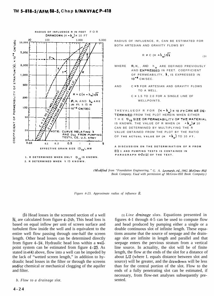
TM 5-818~5/AFM 88-5, Chap 6/NAVFAC P-418
R A D I U S O F I N F L U E N C E R I N F E E T F O R
DRAWDOWN (H - hw) = 10 FT
30 100 1.000 5,00010 ,000
R. H, A N D hW A R E
IN FT; k IS IN
50
2 0
100.03 0.1 0 . 2 0.s 1 2 5
E F F E C T I V E G R A I N S I Z E (D,,$, M M
1 . R D E T E R M I N E D W H E N O N L Y Dlo I S K N O W N .
2 . R D E T E R M I N E D W H E N k IS K N O W N .
.-
R A D I U S O F I N F L U E N C E , R , C A N B E E S T I M A T E D F O R
BOTH ARTESIAN AND GRAVITY FLOWS BY
R = C (H - hw) fi
W H E R E Re H, AND h A R E D E F I N E D P R E V I O U S L Y
A N D EXPREss:D I N F E E T . C O E F F I C I E N T
O F P E R M E A B I L I T Y , k, I S E X P R E S S E D I N
lO-4 C M / S E C .
A N D C = 3 F O R A R T E S I A N A N D G R A V I T Y F L O W S
TO A WELL.
C = 1.5 TO 2.0 FOR A SINGLE LINE OF
W E L L P O I N T S .
T H E V A L U E O F R F O R (H-hW)=lOFT CANBEDE-
TERMINED F R O M T H E P L O T H E R E I N W H E N E I T H E R
T H E 0,0 SIZE OR PERMEABILITY 0~ THE MATERIAL
I S K N O W N . T H E V A L U E O F R W H E N ( H - hw) # 10
C A N B E D E T E R M I N E D B Y M U L T I P L Y I N G T H E R
V A L U E O B T A I N E D F R O M T H E P L O T B Y T H E R A T I O
O F T H E A C T U A L V A L U E O F ( H - h,J TO 10 F T .
A D I S C U S S I O N O N T H E D E T E R M I N A T I O N O F R F R O M
EQ 1 A N D P U M P I N G T E S T S I S C O N T A I N E D I N ,.b.P A R A G R A P H 4-20(3) O F T H E T E X T .
(Mod:&d from “Foundation Engineering, ” G. A. L.eonards, ed., 1962, McGrawHitlBook Company. Used with permission oj McGraw-Hill Book Company.)
Figure 4-23. Approximate radius of influence R.
(b) Head losses in the screened section of a wellHS are calculated from figure 4-24b. This head loss isbased on equal inflow per unit of screen surface andturbulent flow inside the well and is equivalent to theentire well flow passing through one-half the screenlength. Other head losses can be determined directlyfrom figure 4-24. Hydraulic head loss within a well-point system can be estimated from figure 4-25. Asstated in ~(4) above, flow into a well can be impeded bythe lack of “wetted screen length,” in addition to hy-draulic head losses in the filter or through the screensand/or chemical or mechanical clogging of the aquiferand filter.
b. Flow to a drainage slot.
4 - 2 4
(1) Line druinuge slots. Equations presented infigures 4-1 through 4-5 can be used to compute flowand head produced by pumping either a single or adouble continuous slot of infinite length. These equa-tions assume that the source of seepage and the drain-age slot are infinite in length and parallel and thatseepage enters the pervious stratum from a verticalline source. In actuality, the slot will be of finitelength, the flow at the ends of the slot for a distance ofabout Ll2 (where L equals distance between slot andsource) will be greater, and the drawdown will be lessthan for the central portion of the slot. Flow to theends of a fully penetrating slot can be estimated, ifnecessary, from flow-net analyses subsequently pre-sented.
_,

TM 5-818-5/AFM 88-5, Chap WNAVFAC P-418
l’dde 4-1. Index to Figures for Flow, Head, or Drawdown Equutions for Given Corrections
Index Assumed Sourceof Seepage
Drainage System!rype of
FlowPenetration Figure
Flow to aslot Line Line slot A. G. C I 4-1, 4-2
LineTvo-lineTwo-lineCircularCircular
Line slot A; G; C P 4-2 , 4 -3Line slot A, G P, F 4-4!Pvo-line slots A, G I 4-5Circular slots A P. F 4-6, 4-7Rectangular ,
slots A P, F 4-0, 4-9
Flow toveils Circular
CircularCircularCircularCircular
CircularCircular
Single lineSingle lineSingle line
Single lineSingle lineSingle line
Single vellSingle wellSingle vellMultiple veilsCircular, rec-tangular,and tvo-linearrays
Circular arrayCircular and
rectangulararray
Single vell!<iple wellsCircular, line,two-line, andrectangulararrays
Infinite lineInfinite lineInfinite line
A P, F 4-10ci P, F 4-11C I 4-12A, G F 4-13
A, G I 4-14A I 4-15
A I 4-16A, G F 4-17A, G I 4-18
A. G F 4-19A F 4-20A P, F 4-21G I 4-22
Other Approximate radius of influenceHydraulic head loss in a vellHydraulic head loss in various wellpointsEquivalent length of straight pipe for various fittingsShape factors for wells of various penetrations centered
inside a circular sourceFlow and drawdovn for slots from flow-net analysesFlow and dravdown for wells from flow-net analysesDiagrammatic layout of electrical analogy model
4-234-244-254-26
4-274-284-294-30
Note : A = artesian flow; G = gravity flow; C = combined artesian-gravity flow; I = fullypenetrating; P = partially penetrating.
LJ. S. Army Corps of Ergizeers

TY
PE
O
F
P,P
E-L-
,loo/
cl’~
~~
TO
TA
L H
YO
RA
ULIC
HE
AD
LO
SS
IN
A W
EL
L
cHw
) IS
Hw
= H
e +
bls
t H
, +
H
”(1
02
)
WH
ER
Etie
= E
NT
RA
NC
E H
EA
D L
OS
S (
SC
RE
EN
AN
D F
ILT
ER
)
ES
TIM
AT
E F
RO
M C
UR
VE
a
.
Hs
= H
EA
D L
OS
S I
N S
CR
EE
NE
D S
EC
TIO
N O
F W
EL
L:
ES
TIM
AT
E F
RO
M C
UR
VE
b
FO
R A
DIS
TA
NC
E O
F
ON
E-
HA
LF
TH
E S
CR
EE
N L
EN
GT
H.
H, =
HE
AD
LO
SS
WIT
HIN
TH
E R
ISE
R A
ND
CO
NN
EC
TIO
NS
.
ES
TIM
AT
E F
RO
M C
UR
VE
b.
(S
EE
FIG
. 4.2
6 F
OR
TH
E
EQ
UIV
AL
EN
T L
EN
GT
H O
F S
TR
AIG
HT
PIP
E F
OR
VA
RI-
OU
S F
ITT
ING
S.)
Hv
= V
EL
OC
ITY
HE
AD
LO
SS
. E
ST
IMA
TE
FR
OM
CU
RV
E
c
TH
E V
AL
UE
OF
H
MU
ST
EIE
SU
BT
RA
CT
ED
FR
OM
TH
E C
OM
PU
TE
D
VA
LU
E O
F
hw
TO
wO
BT
AIN
TH
E L
IFT
OR
WA
TE
R L
EV
EL
IN
A W
EL
L.
0IO
2030
40
50
WE
LL
,,lS
C,,A
RG
E
PE
R
FT
O
F
SC
RE
EN
, G
PM
(0)
ST
EE
L (
NE
W,
12
50.6
7S
TE
EL
,A
VG
CO
ND
ITIO
NS
110
0.8
3P
VC
(P
OL
YV
INY
L C
HLO
RID
E1
150
0.4
7
CO
RR
UG
AT
ED
ME
TA
L7
0I
.92
IIO
100
1,0
00
to,0
00
10
0,0
00
OIS
CH
AR
GE
, G
PM
BA
SE
D O
N
,,A
2E
N-W
ILL
IAM
S
EQ
UA
TIO
N
WIT
H
C =
1
00
;
MU
LT
IPL
Y
LO
SS
ES
B
Y
clO
O/C
l ‘.
M
FO
R V
AL
”E
S
OF
C
O
T,,E
R T
HA
N 1
00
b)
(Mod
ifie
d fr
om
“Fou
nda
tion
E
ngi
nee
rin
g,”
G.
A.
Leo
nar
ds,
ed.,
1962
, M
cGra
w-H
ill
Boo
k C
ompa
ny.
Use
d w
ith
perm
issi
on
of
McG
raw
-Hil
l B
ook
Com
pany
.)
Fig
ure
4-24
. H
ydra
ulic
hea
d lo
ss i
n a
wel
l.

TO
TA
L H
YD
RA
UL
IC H
EA
D L
OS
S I
N A
WE
LL
PO
INT
(H
J I
S
Hw= H
e t
Hs
t H
r t
H”
WH
ER
EH
e =
EN
TR
AN
CE
HE
AD
LO
SS
(W
EL
LP
OIN
T A
N0
FIL
TE
R)
Hs
= F
RIC
TIO
N b
lEA
D L
OS
S
WlT
tilN
TH
E W
EL
LP
OIN
T
Hr
= F
RIC
TIO
N H
EA
D L
OS
S I
N R
ISE
R,
SW
ING
CO
NN
EC
TIO
N,
AN
D V
AL
VE
Ii”
= V
EL
OC
ITY
HE
AD
LO
SS
IN
RIS
ER
, S
WIN
G C
ON
NE
CT
ION
, A
ND
VA
LV
E
HY
DR
AU
LIC
HE
AD
L
DS
SE
S F
OR
TY
PIC
AL
WE
LL
PO
INT
S A
ND
RIS
ER
S
CA
N B
E E
ST
IMA
TE
D F
RO
M T
HE
PL
OT
SB
EL
OW
.
flN
f SA
ND
T-----l
DG
$-0
30m
mD
Io=
0.1
6 m
m
!,lf
Olll
’.i S
AN
DL
&-0
58m
mI&
- 0.
24 m
m
II d
15
10
Ref
no
. 11
0.5
13
120
010
20
30E
e”
Not
e: H
ead
loss
es i
nclu
de
30th
ose
in w
ing
conn
ectio
n
g;
’ E
20
+b
.E
3t s
.S
‘>Z
10 00
2040
6080
Dis
chxg
e, g
pm
SLO
T O
R M
ESN
RE
FN
O.
WE
LL
PO
lNT
tO
PE
NIN
GN
O.
IN M
M-
-~
1A
AN
D B
, G
RO
OV
ED
SL
OT
122 3 4 5 6 ? 6 9 10 11 12 13 CB D
C,
WIR
E W
RA
P O
NP
ER
FO
RA
TE
D P
IPE
0, W
IRE
MES
H O
NP
ER
FO
RA
TE
D P
IPE
E, W
IRE
ME
SH
ON
PE
RF
OR
AT
ED
PIP
EB
, G
RO
OV
ED
SL
OT
A,
GR
OO
VE
D S
LOT
0. W
IRE
ME
SH
ON
PE
RF
OR
AT
ED
PIP
EA
, G
RO
OV
ED
SL
OT
0, G
RO
OV
ED
SL
OT
F, P
ER
FO
RA
TE
D P
IPE
WIT
H 6
-IN
. P
EA
-GR
AV
EL
FIL
TE
RA
. G
RO
OV
ED
SL
OT
A,
GR
OO
VE
D S
LOT
E,
PE
RF
OR
AT
ED
PIP
EM
E.%
SF,
CO
MM
ER
CIA
LB
RO
NZ
E,
SE
LF
-JE
TT
ING
ME
SH
E,
ST
AIN
LES
SS
TE
EL
S
TY
LE
D
,S
EL
F-J
ET
TIN
G
200.
300.
51
260.
59
260.
59
250.
6325
0.63
260.
59
501.
2?30
0.76
5/3
2 f
N.
3.97
120.
3010
02.
545/
32 I
N.
3.97
40x
450.
31x
0.36
12x
660.
30x
1.73
t E
XC
EP
T F
OR
C,
B,
AN
D D
, W
EL
LP
OIN
TS
AR
EP
LA
IN-T
IP,
2-1
/2-I
N. I
D.
(Modtp
ed f
rom
“F
oun
dati
on E
ngi
nee
rin
g,”
G.
A.
Lxo
nar
ds,
ed.,
1962
, M
cGra
w-H
ill
Boo
k C
ompa
ny.
Use
d w
ith p
erm
issi
on o
f M
cGra
w-H
ill B
ook
Com
pany
.)
Fig
ure
4-25
. H
ydra
ulic
hea
d lo
ss i
n va
riou
s w
ellp
oint
s.

TM 5-818-5/AFM 88-5, ChaP WNAVFAC P-418
(2) Circulur and rectangular slots. Equations forflow and head or drawdown produced by circular andrectangular slots supplied by a circular seepage sourceare given in figures 4-6 through 4-9. Equations forflow from a circular seepage source assume that theslot is located in the center of an island of radius R.For many dewatering projects, R is the radius of influ-ence rather than the radius of an island, and proce-dures for determining the value of R are discussed ina(3) above. Dewatering systems of relatively shortlength are considered to have a circular source wherethey are far removed from a line source such as a riveror shoreline.
(3) Use of slots for designing well systems. Wellscan be substituted for a slot; and the flow Qw, draw-down at the well (H-hw) neglecting hydraulic headlosses at and in the well, and head midway betweenthe wells above that in the wells Ahm can be computedfrom the equations given in figures 4-20, 4-21, and4-22 for a (single) line source for artesian and gravityflow for both “fully” and “partially” penetrating wellswhere the well spacing a is substituted for the lengthof slot x.
(4) Partially penetrating slots, The equations forgravity flow topartially penetrating slots are only con-sidered valid for relatively high-percent penetrations.
c. Flow to wells.(1) Flow to wells from a circular source.
(a) Equations for flow and drawdown producedby a single well supplied by a circular source are givenin figures 4-10 through 4-12. It is apparent from fig-ure 4-11 that considerable computation is required todetermine the height of the phreatic surface and re-sulting drawdown in the immediate vicinity of a grav-ity well (r/h less than 0.3). The drawdown in this zoneusually is not of special interest in dewatering systemsand seldom needs to be computed. However, it is al-ways necessary to compute the water level in the wellfor the selection and design of the pumping equip-ment.
(b) The general equations for flow and draw-down produced by pumping a group of wells suppliedby a circular source are given in figure 4-13. Theseequations are based on the fact that the drawdown atany point is the summation of drawdowns produced atthat point by each well in the system. The drawdownfactors F to be substituted into the general equationsin figure 4-13 appear in the equations for both arte-sian and gravity flow conditions. Consequently, thefactors given in figure 4-14 for commonly used wellarrays are applicable for either condition.
(c) Flow and drawdown for circular well arrayscan also be computed, in a relatively simple manner,by first considering the well system to be a slot, asshown in figure 4-15 or 4-16. However, the piezo-metric head in the vicinity of the wells (or wellpoints)
4-28
will not correspond exactly to that determined for theslot due to convergence of flow to the wells. The piezo-metric head in the vicinity of the well is a function ofwell flow Q; well spacing a; well penetration W; effec-tive well radius rw; aquifer thickness D, or gravity headH; and aquifer permeability k. The equations given infigures 4-15 and 4-16 consider these variables.
(2) Flow to wells from a line source,(a) Equations given in figures 4-17 through
4-19 for flow and drawdown produced by pumping asingle well or group of fully penetrating wells suppliedfrom an infinite line source were developed using themethod of image wells. The image well (a rechargewell) is located as the mirror image of the real wellwith respect to the line source and supplies the per-vious stratum with the same quantity of water as thatbeing pumped from the real well.
(b) The equations given in figures 4-18 and4-19 for multiple~well systems supplied by a linesource are based on the fact that the drawdown at anypoint is the summation of drawdowns produced at thatpoint by each well in the system. Consequently, thedrawdown at a point is the sum of the drawdowns pro-duced by the real wells and the negative drawdownsproduced by the image or recharge wells.
(c) Equations are given in figures 4-20 through4-22 for flow and drawdown produced by pumping aninfinite line at wells supplied by a (single) line source,The equations are based on the equivalent slot assump-tion. Where twice the distance to a single line sourceor 2L is greater than the radius of influence R, thevalue of R as determined from a pumping test or fromfigure 4-23 should be used in lieu of L unless the exca-vation is quite large or the tunnel is long, in which caseequations for a line source or a flow-net analysisshould be used.
(d) Equations for computing the head midwaybetween wells above that in the wells Ahm are notgiven in this manual for two line sources adjacent to asingle line of wells. However, such can be readily de-termined from (plan) flow-net analyses.
(3) Limitations on flow to a partially penetratingwell. Theoretical boundaries for a partially penetrat-ing well (for artesian flow) are approximate relationsintended to present in a simple form the results ofmore rigorous but tedious computations. The rigorouscomputations were made for ratios of R/D = 4.0 and6.7 and a ratio R/rw = 1000. As a consequence, anyagreement between experimental and computedvalues cannot be expected except for the cases withthese particular boundary conditions. In model studiesat the U.S. Army Engineer Waterways ExperimentStation (WES), Vicksburg, Mississippi, the flow from apartially penetrating well was based on the formula:
Qw =2nkD(H - hw)G
ln(R/rw)(4-2)
or
with
whereG =f Z
!s=2llG
ln(R/rW)
quantity shown in equation (6), figure 4-10geometric shape factor
Figure 4-26 shows some of the results obtained at theWES for # for wells of various penetrations centeredinside a circular source. Also presented in figure 4-26are boundary curves computed for well-screen penetra-tions of 2 and 50 percent. Comparison of $ computedfrom WES model data with 4 computed from theboundary formulas indicates fairly good agreement forwell penetrations > 25 percent and values of R/D be-tween about 5 and 15 where R/rW 1 200 to 1000.Other empirical formulas for flow from a partiallypenetrating well suffer from the same limitations.
(4) Partially penetmting wells. The equations forgrauity flow to partially penetrating wells are onlyconsidered valid for relatively high-percent penetra-tions.
4-3. Flow-net analyses.a. Flow nets are valuable where irregular configura-
tions of the source of seepage or of the dewatering sys-tem make mathematical analyses complex or impossi-ble. However, considerable practice in drawing andstudying good flow nets is required before accurateflow nets can be constructed.
b. A flow net is a graphical representation of flow ofwater through an aquifer and defines paths of seepage(flow lines) and contours of equal piezometric head(equipotential lines). A flow net may be constructed torepresent either a plan or a section view of a seepagepattern. Before a sectional flow net can be con-structed, boundary conditions affecting the flow pat-tern must be delineated and the pervious formationtransformed into one where k,, = k (app E). In draw-ing a flow net. the following general rules must be observed:
(1) Flow lines and equipotential lines intersect atright angles and form curvilinear squares or rec-tangles.
(2) The flow between any two adjacent flow linesand the head loss between any two adjacent equipoten-tial lines are equal, except where the plan or sectioncannot be divided conveniently into squares, in whichcase a row of rectangles will remain with the ratio ofthe lengths to the sides being constant.
(3) A drainage surface exposed to air is neither anequipotential nor flow line, and the squares at this sur-face are incomplete; the flow and equipotential linesneed not intersect such a boundary at right angles.
TM S-818-S/AFM 88-5, Chap 4/NAVFAC P-418
(4) For gravity flow, equipotential lines intersectthe phreatic surface at equal intervals of elevation,each interval being a constant fraction of the total nethead.
c. Flow nets are limited to analysis in two dimen-sions; the third dimension in each case is assumed in-finite in extent. An example of a sectional flow netshowing artesian flow from two line sources to a par-tially penetrating drainage slot is given in figure4-27a. An example of a plan flow net showing artesianflow from a river to a line of relief wells is shown infigure 4-27b.
d. The flow per unit length (for sectional flow nets)or depth (for plan flow nets) can be computed bymeans of equations (1) and (2), and (5) and (6), respec-tively (fig. 4-27). Drawdowns from either sectional orplan flow nets can be computed from equations (3) and(4) (fig. 4-27). In plan flow nets for artesian flow, theequipotential lines correspond to various values of H-h, whereas for gravity flow, they correspond to Hz-h’.Since section equipotential lines for gravity flow con-ditions are curved rather than vertical, plan flow netsfor gravity flow conditions give erroneous results forlarge drawdowns and should always be used with cau-tion.
e. Plan flow nets give erroneous results if used toanalyze partially penetrating drainage systems, the er-ror being inversely proportional to the percentage ofpenetration. They give fairly accurate results if thepenetration of the drainage system exceeds 80 percentand if the heads are adjusted as described in the fol-lowing paragraph.
f. In previous analyses of well systems by means offlow nets, it was assumed that dewatering or drainagewells were spaced sufficiently close to be simulated bya continuous drainage slot and that the drawdown(H-hr) required to dewater an area equaled the aver-age drawdown at the drainage slot or in the lines ofwells (H-he). These analyses give the amount of flowQr that must be pumped to achieve H-hr, but do notgive the drawdown at the wells. The drawdown at thewells required to produce H-hD downstream or withina ring of wells can be computed (approximately) for ar-tesian flow from plan flow nets by the equationsshown in figure 4-28 if the wells have been spacedproportional to the flow lines as shown in figure 4-27.The drawdown at fully penetrating gravity wells canalso be computed from equations given in figure 4-28.
4-4. Electrical analogy seepage models.a. The laws governing flow of fluids through porous
media and flow of electricity through pure resistanceare mathematically similar. Thus, it is feasible to useelectrical models to study seepage flows and pressure


TM S-818-5/AFM 88-5, Chap WNAVFAC P-418
Impervious
SECTIONAL FLOW NET (ARTESIAN)
(aI
SECTIONAL FLOW NET
FLOW
PLAN FLOW NET
tb)
A R T E S I A N q = kH*$ (1) G R A V I T Y q = kw$ (2)
DRAWDOWN AT ANY POINT
ARTESIAN H-hZH@; “eI 3
eG R A V I T Y Hz - h2 =T k2 -(ho + hs?-j i 41
e
PLAN FLOWNET
FLOW
A R T E S I A N QT = km1 $ kw$G R A V I T Y QT =-
2
DRAWDOWN AT ANY POINT
USE EQ ‘3 AND 4, FOR ARTESIAN AND GRAVITY FLOW CONDITIONS, RESPECTIVELY.
H’ =t-+he H" z ,, ' - ht Nf$ = SHAPE FACTOR =r Nf = NUMBER OF FLOW CHANNELS IN NET
Ne = TOTAL NUMBER OF EQUIPOTENTIAL DROPS ISETWEEtl FULL HEAD, H, AND HEAD AT EXIT, h e
“e = NUMBER OF EQUIPOTENTIAL DROPS FROM EXIT TO POINT AT WHICH HEAD, h, IS DESIRED
hols SHOWN IN FIG. 4-1
SEE FIG. 4-29 FOR HEAD CORRECTION FACTORS,
(hfodljTed_frorn “Foundation Engineering, ” G. A. Ltonards, ed., 1962, McGraw-HillBook Company. Used wirh permission of McGraw-Hill Book Company.)
Figure 4-27. Flow and drawdown to slots computed from flow nets.
distribution for various seepage conditions. Both two-and three-dimensional models can be used to solveseepage problems.
b. Darcy’s law for two-dimensional flow of water
(previously identified as equation (1) in fig. 4-27)through soil can be expressed for unit length of soilformations as follows:
q = kH’$ (4-3)
4-31

TM 5-818-5/AFM 88-5, Chap WNAVFAC P-418
C O N S T R U C T P L A N F L O W N E T . S P A C E W E L L S P R O P O R T I O N A L T O F L O W L I N E S . C O M P U T E T O T A L F L O W
T O S Y S T E M F R O M E Q 5 F O R A R T E S I A N F L O W O R E Q 6 F O R G R A V I T Y F L O W (FIG. 4-26). A S S U M E IN EQ 5
H* = H - hD. S E E F I G . 4 - 2 0 , b, c; 4-22, b; A N D 4 - 2 6 F O R E X P L A N A T I O N O F T E R M S .
A R T E S I A N F L O W
F L O W T O E A C H W E L L
QTQw =y
W H E R E ” = N U M B E R O F W E L L S IN T H E S Y S T E M
DRAWDOWN A T W E L L S
F U L L Y P E N E T R A T I N G
P A R T I A L L Y P E N E T R A T I N G
Qwti-hW==
(1)
W H E R E 0 I S O B T A I N E D F R O M F I G . 4 - 2 1 t.3
H E A D I N C R E A S E S M I D W A Y B E T W E E N A N D D O W N S T R E A M O F W E L L S M A Y B E C O M P U T E D F R O M E Q U A T I O N S
G I V E N I N F I G . 4 - 2 0 A N D 4-21.
G R A V I T Y F L O W
F L O W T O E A C H W E L L
U S E EQ 1
DRAWDOWN A T F U L L Y P E N E T R A T I N G W E L L
H E A D I N C R E A S E S M I D W A Y B E T W E E N A N D D O W N S T R E A M O F W E L L S M A Y B E C O M P U T E D F R O M E Q U A T I O N S
G I V E N I N FIG. 4-22.
t T H E A V E R A G E W E L L S P A C I N G M A Y B E U S E D T O C O M P U T E eO, e,,, , A N D T H E DRAWDOWN A T A N D
B E T W E E N W E L L S .
U.S. Army Corps of Engineers
Figure 4-28. Flow and drawdown to wells computed from flow-net analyses
sistance as follows:rate of flowcoefficient of permeabilitydifferential headshape factor dependent on the geometry ofthe system
where
I =c, Ohm’s law expresses the analogous condition for E =
steady flow of electricity through a medium of pure re- P Z
4 - 3 2
rate of flow of electricitypotential difference or voltagespecific resistance of electrolyte
(4-4)

TM S-818-5/AFM 88-5, Chap 6/NAVFAC P-418
Since the permeability in fluid flow is analogous to thereciprocal of the specific resistance for geometricallysimilar mediums, the shape factors for Darcy’s law andOhm’s law are the same.
flow net constructed using an electrical analogy modelmay be analyzed in the same manner as one con-structed as in paragraph 4-3.
d. A two-dimensional flow net can be constructed e. Equipment for conducting three-dimensionalusing a scale model of the flow and drainage system electrical analogy model studies is available at themade of a conductive material representing the porous WES. The equipment consists basically of a largemedia (graphite-treated paper or an electrolytic solu- plexiglass tank filled with diluted copper sulfate solu-tion), copper or silver strips for source of seepage and tion and having a calibrated, elevated carrier assemblydrainage, and nonconductive material representing for the accurate positioning of a point electrode probeimpervious flow boundaries, The electrical circuit con- anywhere in the fluid medium. A prototype is simu-sists of a potential applied across the model and a lated by fabricating appropriately shaped and sealedWheatstone bridge to control intermediate potentials source and sink configurations and applying an elec-on the model (fig. 4-29). The flow net is constructed by trical potential across them. The model is particularlytracing lines of constant potential on the model, thus useful for analyzing complex boundary conditions thatestablishing the flow-net equipotential lines after cannot be readily analyzed by two-dimensional tech-which the flow lines are easily added graphically. A niques.
DEWATERING
SOURCE OF
SEEPAGE
(COPPER STRIP)
(COPPER STRIPJ
0 = kti#$
S E E PARAGRAPM 4 - 3
FO7 E X P L A N A T I O N O F T E R M S
A N D P R O C E D U R E F O R
D E T E R M I N I N G $
T O D.C. P O W E R S U P P L Y
Nf = 2 1
Ne = 3
U.S. Army Corps of Engineers
Figure 4-29. Diugrammatic layout of electricul anulogy model.
(Fruco & Associates, Inc.)
4-33

TM 5-818-5/AFM 88-5, Chap 6/NAVFAC P-418
4-5. Numerical analyses.u. Many complex seepage problems, including such
categories as steady confined, steady unconfined, andtransient unconfined can be solved using the finite ele-ment method. Various computer codes are available atthe WES and the NAVFAC program library to handlea variety of two- and three-dimensional seepage prob-lems. The codes can handle most cases of nonhomoge-neous and anisotropic media.
b. A general computer code for analyzing partiallypenetrating random well arrays has been developedbased on results of three-dimensional electrical anal-ogy model tests at the WES. The computer code pro-vides a means for rapidly analyzing trial well systemsin which the number of wells and their geometric con-figuration can be varied to determine quantities ofseepage and head distributions. Wells of differentradii and penetrations can be considered in the analy-sis.
4-6. Wellpoints, wells, and filters. Wellsand wellpoints should be of a type that will prevent in-filtration of filter material or foundation sand, offerlittle resistance to the inflow of water, and resist cor-rosion by water and soil. Wellpoints must also havesufficient penetration of the principal water-carryingstrata to intercept seepage without excessive residualhead between the wells or within the dewatered area.
a. Wellpoints. Where large flows are anticipated, ahigh-capacity type of wellpoint should be selected. Theinner suction pipe of self-jetting wellpoints should per-mit inflow of water with a minimum hydraulic headloss. Self-jetting wellpoints should be designed so thatmost of the jet water will go out the tip of the point,with some backflow to keep the screen flushed cleanwhile jetting the wellpoint in place.
(1) Wellpoint screens. Generally, wellpoints arecovered with 30- to 60-mesh screen or have an equiva-lent slot opening (0.010 to 0.025 inch). The meshshould meet filter criteria given in I below. Where thesoil to be drained is silty or fine sand, the yield of thewellpoint and its efficiency can be greatly improved byplacing a relatively uniform, medium sand filteraround the wellpoint. The filter should be designed inaccordance with criteria subsequently set forth in c be-low. A filter will permit the use of screens or slots withlarger openings and provide a more pervious materialaround the wellpoint, thereby increasing its effectiveradius (d below).
(2) Wellpoint hydraulics. The hydraulic headlosses in a wellpoint system must be considered in de-signing a dewatering system. These losses can be esti-mated from figure 4-25.
b. Wells. Wells for temporary dewatering and per-manent drainage systems may have diameters ranging
from 4 to 18 inches with a screen 20 to 75 feet long de-pending on the flow and pump size requirements.
(1) Well screens. Screens generally used for de-watering wells are slotted (or perforated) steel pipe,perforated steel pipe wrapped with galvanized wire,galvanized wire wrapped and welded to longitudinalrods, and slotted polyvinyl chloride (PVC) pipe, Riserpipes for most dewatering wells consist of steel or PVCpipe. Screens and riser for permanent wells are usuallymade of stainless steel or PVC. Good practice dictatesthe use of a filter around dewatering wells, which per-mits the use of fairly large slots or perforations, usual-ly 0.025 to 0.100 inch in size. The slots in well screensshould be as wide as possible but should meet criteriagiven in c below.
(2) Open screen area. The open area of a wellscreen should be sufficient to keep the entrance veloc-ity for the design flow low to reduce head losses and tominimize incrustation of the well screen in certaintypes of water. For temporary dewatering wells in-stalled in nonincrusting groundwater, the entrance ve-locity should not exceed about 0.15 to 0.20 foot persecond; for incrusting groundwater, the entrance ve-locity should not exceed 0.10 to 0.20 foot per second.For permanent drainage wells, the entrance velocityshould not exceed about 0.10 foot per second. As theflow to and length of a well screen is usually dictatedby the characteristics of the aquifer and drawdown re-quirements, the required open screen area can be ob-tained by using a screen of appropriate diameter witha maximum amount of open screen area.
(3) Well hydruulics. Head losses within the wellsystem discussed in paragraph 4-2u(5) can be esti-mated from figure 4-24.
c. Filters. Filters are usually 3 to 5 inches thick forwellpoints and 6 to 8 inches thick for large-diameterwells (fig. 4-30). To prevent infiltration of the aquifermaterials into the filter and of filter materials into thewell or wellpoint, without excessive head losses, filtersshould meet the following criteria:
Screen-filter criteria
Slot or screen openings $ minimum filter DUO
Filter-aquifer criteria
Max filter Di55 5;
Max filter DUO
Min aquifer DES Min aquifer DUOs 25;
Min filter Dls
Max aquifer Dls22to5
If the filter is to be tremied in around the screen for awell or wellpoint, it may be either uniformly or ratherwidely graded; however, if the filter is not tremiedinto place, it should be quite uniformly graded (D&D105 3 to 4) and poured in around the well in a heavy,continuous stream to minimize segregation.
4-34

TM 5-818-S/AFM 88-5, Chap WNAVFAC P-418
.
4-35

TM 5-818-5/AFM 88-5, Chap WNAVFAC P-418
d. Effective well radius. The “effective” radius r,., ofa well is that well radius which would have no hy-draulic entrance loss &. If well entrance losses areconsidered separately in the design of a well or systemof wells, rW for a well or wellpoint without a filter maybe considered to be one-half the outside diameter ofthe well screens; where a filter has been placed arounda wellpoint or well screen, rW may generally be con-sidered to be one-half the outside diameter or theradius of the filter.
e. Well penetration. In a stratified aquifer, the ef-fective well penetration usually differs from that com-puted from the ratio of the length of well screen to to-tal thickness of the aquifer. A method for determiningthe required length of well screen W to achieve an ef-fective penetration W in a stratified aquifer is given inappendix E.
f. Screen length, penetmtion, and diameter. Thelength and penetration of the screen depends on thethickness and stratification of the strata to be de-watered (para 4-2u(6)). The length and diameter of thescreen and the area of perforations should be suffi-cient to permit the inflow of water without exceedingthe entrance velocity given in b(2) above. The “wettedscreen length LB” (or h,.,. for each stratum to be de-watered) is equal to or greater than Q/q (para 4-2u(4)and (6)). The diameter of the well screen should be atleast 3 to 4 inches larger than the pump bowl or motor.
4-7. Pumps, headers, and dischargepipes. The capacity of pumps and piping should al-low for possible reduction in efficiency because of in-
crustation or mechanical wear caused by prolongedoperation. This equipment should also h designed _with appropriate valves, crossovers, and standby unitsso that the system can operate continuously, regard-less of interruption for routine maintenance or break-down.
a. Centrifugal and wellpoin t pumps.(1) Centrifugal pumps can be used as sump
pumps, jet pumps, or in combination with an auxiliaryvacuum pump as a wellpoint pump. The selection of apump and power unit depends on the discharge, suc-tion lift, hydraulic head losses, including velocity headand discharge head, air-handling requirement, poweravailable, fuel economy, and durability of unit. A well-point pump, consisting of a self-priming centrifugalpump with an attached auxiliary vacuum pump,should have adequate air-handling capacity and becapable of producing a vacuum of at least 22 to 25 feetof water in the headers. The suction lift of a wellpointpump is dependent on the vacuum available at thepump bowl, and the required vacuum must be con-sidered in determining the pumping capacity of thepump. Characteristics of a typical 8-inch wellpointpump are shown in figure 4-31. Characteristics of atypical wellpoint pump vacuum unit are shown in fig-ure 4-32. Sump pumps of the centrifugal type shouldbe self-priming and capable of developing at least 20feet of vacuum. Jet pumps are high head pumps; typ-ical characteristics of a typical 6-inch jet pump areshown in figure 4-33.
(2) Each wellpoint pump should be provided withone connected standby pump so as to ensure continuity
140 l-I
Pump speed- 1,600 rpm
Discharge, gpm
(Courtesy of Gr#n Wellpoint Corp. and “Foundation Engineecing, ”McGraw Hill Book Company)
Figure 4-31. Churucteristics oj8.irzch Griffin ~ellpohtpump.
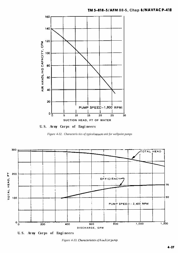
TM 5-818-5/AFM 88-5, Chap WNAVFAC P-418
PUMk SPEEb - 1,800 RPM I
01 I I I I0 5 10 15 20 25 30
SUCTION HEAD, FT OF WATER
U.S. Army Corps of Engineers
Figure 4-32. Characteris tics of typical uacuwn unit for wellpoint pumps
DISCHARGE, GPM
U.S. Army Corps of Engineers
Figure 4-33. Chumcteristics of 6.inchjetpump.

TM 5-818-S/AFM 88-5, Chap WNAVFAC P-418
-
of operation in event of pump or engine failure, or forrepair or maintenance. By overdesigning the headerpipe system and proper placement of valves, it may bepossible to install only one standby pump for everytwo operational pumps. If electric motors are used forpowering the normally operating pumps, the standbypumps should be powered with diesel, natural or LPgas, or gasoline engines. The type of power selectedwill depend on the power facilities at the site and theeconomics of installation, operation, and maintenance,It is also advisable to have spare power units on site inaddition to the standby pumping units. Automaticswitches, starters, and valves may be required if fail-ure of the system is critical.
4-38
b. Deep-well pumps.(1) Deep-well turbine or submersible pumps are
generally used to pump large-diameter deep wells andconsist of one or more stages of impellers on a verticalshaft (fig. 4-34). Turbine pumps can also be used assump pumps, but adequate stilling basins and trashracks are required to assure that the pumps do not be-come clogged. Motors of most large-capacity turbinepumps used in deep wells are mounted at the groundsurface. Submersible pumps are usually used forpumping deep, low-capacity wells, particularly if avacuum is required in the well.
-.(2) In the design of deep-well pumps, consider-ation must be given to required capacity, size of well

TM 5-818-5/AFM 88-5, Chap WNAVFAC P-418
Table 4-2. Capacity of Various Size Submersible and Deep- Well Turbine Pumps
Maximum Pump Ins ide DiameterBowl or Motor Size of Well
inches inches
ApproximateMaximum Capacity
ga l lons per minuteDeep Well Submersible
4 5-6 905 6-8 1606 8-10 4508 10-12 600
10 12-14 1,20012 14-16 1,80014 16-18 2,40016 18-20 3,000
70- -
250400700
1,100- -
U. S. Army Corps of Engineers
screen and riser pipe, total pumping head, and the low-ered elevation of the water in the well. The diameter ofthe pump bowl must be determined before the wellsare installed, as the inside diameter of the well casingshould be at least 3 to 4 inches larger in diameter thanthe pump bowl. Approximate capacities of various tur-bine pumps are presented in table 4-2. The character-istics of a typical three-stage, lo-inch turbine pumpare shown in figure 4-35.
(3) Submersible pumps require either electricpower from a commercial source or one or more motorgenerators. If commercial power is used, 75 to 100 per-cent of (connected) motor generator power, with auto-matic starters unless operational personnel are onduty at all times, should be provided as standby for thecommercial power. Spare submersible pumps, general-ly 10 to 20 percent of the number of operating pumps,as well as spare starters, switches, heaters, and fuses,should also be kept at the site.
(4) Deep-well turbine pumps can be powered witheither electric motors or diesel engines and geardrives. Where electric motors are used, 50 to 100 per-cent of the pumps should be equipped with combina-tion gear drives connected to diesel (standby) engines.The number of pumps so equipped would depend uponthe criticality of the dewatering or pressure reliefneeds. Motor generators may also be used as standbyfor commercial power. For some excavations and sub-surface conditions, automatic starters may be requiredfor the diesel engines or motor generators being usedas backup for commercial power.
c, Turbovacuum pumps. For some wellpoint sys-tems requiring high pumping rates, it may lo desirable
(Courtesy of Foirbonks Morse, Inc., Pump Division)
Figure 4-35, Rating curoes for a three-stage 16inch-high capacitydeep-well pump.
to connect the header pipe to a 30- or 36-inch collec-tion tank about 20 or 30 feet deep, sealed at the bot-tom and top, and pump the flow into the tank with ahigh-capacity deepwell turbine pump using a separatevacuum pump connected to the top of the tank to pro-duce the necessary vacuum in the header pipe for thewells or wellpoints.
d. Header pipe.(1) Hydraulic head losses caused by flow through
the header pipe, reducers, tees, fittings, and valvesshould be computed and kept to a minimum (1 to 3feet) by using large enough pipe. These losses can becomputed from equivalent pipe lengths for various fit-tings and curves.
4-39

WI 5-818-5/AFM 88-5, Chap WNAVFAC P-418
(2) Wellpoint header pipes should be installed asclose as practical to the prevailing groundwater eleva-tion and in accessible locations. Wellpoint pumpsshould be centrally located so that head losses to theends of the system are balanced and as low as possible.If suction lift is critical, the pump should be placed lowenough so that the pump suction is level with theheader, thereby achieving a maximum vacuum in theheader and the wellpoints. If construction is to be per-formed in stages, sufficient valves should be providedin the header to permit addition or removal of portionsof the system without interrupting operation of the re-mainder of the system. Valves should also be locatedto permit isolation of a portion of the system in caseconstruction operations should break a swing connec-tion or rupture a header.
(3) Discharge lines should be sized so that thehead losses do not create excessive back pressure onthe pump. Ditches may be used to carry the waterfrom the construction site, but they should be locatedwell back of the excavation and should be reasonablywatertight.
4-8. Factors of safety.CL. General. The stability of soil in areas of seepage
emergence is critical in the control of seepage. The exitgradient at the toe of a slope or in the bottom of an ex-cavation must not exceed that which will cause surfaceraveling or sloughing of the slope, piping, or heave ofthe bottom of the excavation.
b. Uplift. Before attempting to control seepage, ananalysis.should be made to ensure that the seepage oruplift gradient is equal to or less than that computedfrom the following equations:
i< Yh-
yw (FS = 1.25 to 1.5)(4-5)
or
wherei=
y& =Z
:; Z
T=
L=
Ah = (r&JTyw (FS = 1.25 to 1.5)
(4-6) -
seepage gradient Ah/Lsubmerged unit weight of soilunit weight of waterartesian head above bottom of slope or exca-vationthickness of less pervious strata overlying amore pervious stratumdistance through which Ah acts
In stratified subsurface soils, such as a course-grainedpervious stratum overlain by a finer grained stratumof relatively low permeability, most of the head lossthrough the entire section would probably occurthrough the finer grained material. Consequently, afactor of safety based on the head loss through the topstratum would probably indicate a more critical condi-tion than if the factor of safety was computed from thetotal head loss through the entire section. Also, whengradients in anisotropic soils are determined fromflow nets, the distance over which the head is lostmust be obtained from the true section rather than thetransformed section.
c. Piping. Piping cannot be analyzed by any rationalmethod. In a study of’piping beneath hydraulic struc-tures founded on granular soils, it was recommendedthat the (weighted) creep ratio C& should equal or ex-ceed the values shown in table 4-3 for various types ofgranular soils,
I vertical seepage paths
cW=+ 113 I horizontal seepage paths
H-he (4-7)
Table 4-3. Minimum Creep Ratios for Various Granular Soils
S o i l Creep Rat io
very f i n e s a n d o r s i l t 8 . 5Fine sand 7Medium sand 6Coarse sand 5F ine g rave l 4Medium gravel 3 .5Coarse g rave l inc lud ing cobbles 3Boulders with some cobbles and gravel 2 .5
From “Securityfrom Under-Seepage Masonry Dams, “by E. W. Lane, pp. 123S-I272.Transactions, American Society of Civil Engineers, 1935.
4 - 4 0


TM 5-818-5/AFM 88-5, Chap WNAVFAC P-418
In addition to these factors of safety being applied todesign features of the system, the system should bepump-tested to verify its adequacy for the maximumrequired groundwater lowering and maximum river orgroundwater table likely (normally a frequency of oc-currence of once in 5 to 10 years for the period of expo-sure) to occur.
4-9. Dewatering open excavations. An ex-cavation can be dewatered or the artesian pressure re-lieved by one or a combination of methods described inchapter 2. The design of dewatering and groundwatercontrol systems for open excavations, shafts, and tun-nels is discussed in the following paragraphs. Ex-amples of design for various types of dewatering andpressure relief systems are given in appendix D.
a. Trenching and sump pumping.(1) The applicability of trenches and sump pump-
ing for dewatering an open excavation is discussed inchapter 2. Where soil conditions and the depth of anexcavation below the water table permit trenching andsump pumping of seepage (fig. 2-l), the rate of flowinto the excavation can be estimated from plan andsectional flow analyses (fig, 4-27) or formulas pre-sented in paragraphs 4-2 through 4-5.
(2) Where an excavation extends into rock andthere is a substantial inflow of seepage, perimeterdrains can be installed at the foundation level outsideof the formwork for a structure. The perimeter drain-age system should be connected to a sump sealed offfrom the rest of the area to be concreted, and the seep-age water pumped out. After construction, the drain-age system should be grouted. Excessive hydrostaticpressures in the rock mass endangering the stability ofthe excavated face can be relieved by drilling 4-inch-diameter horizontal drain holes into the rock at ap-proximately lo-foot centers. For large seepage inflow,supplementary vertical holes for deep-well pumps at50- to lOO-foot intervals may be desirable for tempo-rary lowering of the groundwater level to provide suit-able conditions for concrete placement.
b. Wellpoint system. The design of a line or ring ofwellpoints pumped with either a conventional well-point pump or jet-eductors is generally based on math-ematical or flow-net analysis of flow and drawdown toa continuous slot (para 4-2 through 4-5).
(1) Conventional wellpoint system. The draw-down attainable per stage of wellpoints (about 15 feet)is limited by the vacuum that can be developed by thepump, the height of the pump above the header pipe,and hydraulic head losses in the wellpoint and collec-tor system. Where two or more stages of wellpoints arerequired, it is customary to design each stage so that itis capable of producing the total drawdown requiredby that stage with none of the upper stages function-ing. However, the upper stages are generally left in so
4-42
that they can be pumped in the event pumping of thebottom stage of wellpoints does not lower the watertable below the excavation slope because of stratifica-tion, and so that they can be pumped during backfill-ing operations.
-.’
(u) The design of a conventional wellpoint sys-tem to dewater an open excavation, as discussed inparagraph 4-2b, is outlined below.
Step 1. Select dimensions and groundwater co-efficients (H, L, and k) of the formation to be de-watered based on investigations outlined in chapter 3.
Step 2. Determine the drawdown required todewater the excavation or to dewater down to the nextstage of wellpoints, based on the maximum ground-water level expected during the period of operation.
Step 3. Compute the head at the assumed slot(he or hO) to produce the desired residual head ho in theexcavation.
Step 4. Compute the flow per lineal foot ofdrainage system to the slot QP.
Step 5. Assume a wellpoint spacing a and com-pute the flow per wellpoint, QW = aQP.
Step 6. Calculate the required head at the well-point hW corresponding to 4.
Step 7. Check to see if the suction lift that canbe produced by the wellpoint pump V will lower thewater level in the wellpoint to h,+(p) as follows:
wherev =M=
Hc =
Hw =
VLM-hw(p)+Hc+Hw (4-8) __
vacuum at pump intake, feet of waterdistance from base of pervious strata topump intake, feetaverage head loss in header pipe from well-point, feethead loss in wellpoint, riser pipe, and swingconnection to header pipe, feet
Step 8. Set the top of the wellpoint screen atleast 1 to 2 feet or more below hW-HW to provide ade-quate submergence of the wellpoint so that air will notbe pulled into the system.
(b) An example of the design of a two-stage well-point system to dewater an excavation is illustrated infigure D-l, appendix D.
(c) If an excavation extends below an aquiferinto an underlying impermeable soil or rock forma-tion, some seepage will pass between the wellpoints atthe lower boundary of the aquifer. This seepage maybe intercepted with ditches or drains inside the excava-tion and removed by sump pumps. If the underlyingstratum is a clay, the wellpoints may be installed inholes drilled about 1 to 2 feet into the clay and back-filled with filter material, By this procedure, the waterlevel at the wellpoints can be maintained near the bot-tom of the aquifer, and thus seepage passing betweenthe wellpoints will be minimized. Sometimes theseprocedures are ineffective, and a small dike in the ex-
_.

cavation just inside the toe of the excavation may berequired to prevent seepage from entering the workarea. Sump pumping can be used to remove waterfrom within the diked area.
(2) Jet-eductor (well or) wellpoint systems. Flowand drawdown to a jet-eductor (well or) wellpoint sys-tem can be computed or analyzed as discussed in para-graph 4-2b. Jet-eductor dewatering systems can be de-signed as follows:
Step 1. Assume the line or ring of wells or well-points to be a drainage slot.
Step 2. Compute the total flow to the system forthe required drawdown and penetration of the wellscreens.
Step 3. Assume a well or wellpoint spacing thatwill result in a reasonable flow for the well or well-point and jet-eductor pump.
Step 4. Compute the head at the well or well-point hw required to achieve the desired drawdown.
Step 5. Set eductor pump at M = hw-Hw withsome allowance for future loss of well efficiency.The wells or wellpoints and filters should be selectedand designed in accordance with the criteria set forthunder paragraph 4-6.
(u) If the soil formation being drained is strati-fied and an appreciable flow of water must be draineddown through the filter around the riser pipe to thewellpoint, the spacing of the wellpoints and the perme-ability of the filter must be such that the flow fromformations above the wellnoints does not exceed
whereQw =kv =A =i=
Q,v = ihi (4-9
flow from formation above wellpointvertical permeability of filterhorizontal area of filtergradient produced by gravity = 1.0
Substitution of small diameter well screens for well-points may be indicated for stratified formations.Where a formation is stratified or there is little avail-able submergence for the wellpoints, jet-eductor well-points and risers should be provided with a perviousfilter, and the wellpoints set at least 10 feet back fromthe edge of a vertical excavation.
(b) Jet-eductor pumps may be powered withindividual small high-pressure centrifugal pumps orwith one or two large pumps pumping into a singlepressure pipe furnishing water to each eductor with asingle return header. With a single-pump setup, thewater is usually circulated through a stilling tank withan overflow for the flow from wells or wellpoints (fig.2-6). Design of jet eductors must consider the staticlift from the wells or wellpoints to the water level inthe recirculation tank; head loss in the return riserpipe; head loss in the return header; and flow from thewellpoint. The (net) capacity of a jet-eductor pump de-pends on the pressure head, input flow, and diameter
TM 5-818-5/AFM 88-5, Chap 6/NAVFAC P-418
of the jet nozzle in the pump. Generally, a jet-eductorpump requires an input flow of about 2 to 2% timesthe flow to be pumped depending on the operatingpressure and design of the nozzle. Consequently, ifflow from the wells or wellpoints is large, a deep-wellsystem will be more appropriate, The pressure headersupplying a system of jet eductors must be of such sizethat a fairly uniform pressure is applied to all of theeductors.
(3) Vacuum wellpoint system. Vacuum wellpointsystems for dewatering fine-g-rained soils are similarto conventional wellpoint systems except the wellpointand riser are surrounded with filter sand that is sealedat the top, and additional vacuum pump capacity isprovided to ensure development of the maximum vac-uum in the wellpoint and filter regardless of air loss.In order to obtain 8 feet of vacuum in a wellpoint andfilter column, with a pump capable of maintaining a25foot vacuum in the header, the maximum lift is25-8 or 17 feet. Where a vacuum type of wellpointsystem is required, the pump capacity is small. The ca-pacity of the vacuum pump will depend on the air per-meability of the soil, the vacuum to be maintained inthe filter, the proximity of the wellpoints to the exca-vation, the effectiveness of the seal at the top of thefilter, and the number of wellpoints being pumped. Invery fine-g-rained soils, pumping must be continuous.The flow may be so small that water must be added tothe system to cool the pump properly.
c, Electroosmosis(1) An electroosmotic dewatering system consists
of anodes (positive electrodes, usually a pipe or rod)and cathodes (negative electrodes, usually wellpointsor small wells installed with a surrounding filter),across which a d-c voltage is applied. The depth of theelectrodes should be at least 5 feet below the bottom ofthe slope to be stabilized. The spacing and arrange-ment of the electrodes may vary, depending on thedimensions of the slope to be stabilized and the voltageavailable at the site. Cathode spacings of 25 to 40 feethave been used, with the anodes installed midway be-tween the cathodes. Electrical gradients of 1.5- to 4-volts-per-foot distance between electrodes have beensuccessful in electroosmotic stabilization. The electri-cal gradient should be less than about 15 volts per footof distance between electrodes for long-term installa-tions to prevent loss in efficiency due to heating theground. Applied voltages of 30 to 100 volts are usuallysatisfactory; a low voltage is usually sufficient if thegroundwater has a high mineral content.
(2) The discharge of a cathode wellpoint may beestimated from the equation
Qe = k&az (4-10)where
ke = coefficient of electroosmotic permeability
4-43

TM S-818-5/AFM 88-5, Chap WNAVFAC P-418
(assume 0.98 x 10m4 feet per second per voltper foot)
L = electrical gradient between electrodes, voltsper foot
a = effective spacing of wellpoints, feetz = depth of soil being stabilized, feet
Current requirements commonly range between 15and 30 amperes per well, and power requirements aregenerally high. However, regardless of the expense ofinstallation and operation of an electroosmotic de-watering system, it may be the only effective means ofdewatering and stabilizing certain silts, clayey silts,and clayey silty sands. Electroosmosis may not beapplicable to saline soils because of high current re-quirements, nor to organic soils because of environ-mentally objectionable effluents, which may be un-sightly and have exceptionally high pH values.
d. Deep-well systems(1) The design and analysis of a deep-well system
to dewater an excavation depends upon the configura-tion of the site dewatered, source of seepage, type offlow (artesian and gravity), penetration of the wells,and the submergence available for the well screenswith the required drawdown at the wells. Flow anddrawdown to wells can be computed or analyzed as dis-cussed in paragraph 4-2b.
(2) Methods are presented in paragraphs 4-2b and4-3 whereby the flow and drawdown to a well systemcan be computed either by analysis or by a flow net as-suming a continuous slot to represent the array ofwells, and the drawdown at and between wells com-puted for the actual well spacing and location. Exam-ples of the design of a deep-well system using thesemethods and formulas are presented in figures D-2and D-3.
(3) The submerged length and size of a well screenshould be checked to ensure that the design flow perwell can be achieved without excessive screen entrancelosses or velocities. The pump intake should be set sothat adequate submergence (a minimum of 2 to 5 feet)is provided when all wells are being pumped. Wherethe type of seepage (artesian and gravity) is not wellestablished during the design phase, the pump intakeshould be set 5 to 10 feet below the design elevation toensure adequate submergence. Setting the pump bowlbelow the expected drawdown level will also facilitatedrawdown measurements,
e. Combined systems.(1) Well and wellpoint systems. A dewatering sys-
tem composed of both deep wells and wellpoints maybe appropriate where the groundwater table has to belowered appreciably and near to the top of an im-permeable stratum. A wellpoint system alone wouldrequire several stages of wellpoints to do the job, and awell system alone would not be capable of lowering the
4-44
groundwater completely to the bottom of the aquifer.A combination of deep wells and a single stage of well-points may permit lowering to the desired level. The ‘-.advantages of a combined system, in which wells areessentially used in place of the upper stages of well-points, are as follows:
(a) The excavation quantity is reduced by theelimination of berms for installation and operation ofthe upper stages of wellpoints.
(b) The excavation can be started without a de-lay to install the upper stages of wellpoints.
(c) The deep wells installed at the top of theexcavation will serve not only to lower the groundwa-ter to permit installation of the wellpoint system butalso to intercept a significant amount of seepage andthus reduce the flow to the single stage of wellpoints.A design example of a combined deep-well and well-point system is shown in figure D-4,
(2) Sand drains with deep wells and wellpoints,Sand drains can be used to intercept horizontal seep-age from stratified deposits and conduct the watervertically downward into a pervious stratum that canbe dewatered by means of wells or wellpoints. The lim-iting feature of dewatering by sand drains is usuallythe vertical permeability of the sand drains itself,which restricts this method of drainage to soils of lowpermeability that yield only a small flow of water.Sand drains must be designed so that they ~111 inter-cept the seepage flow and have adequate capacity to -_allow the seepage to drain downward without any backpressure. To accomplish this, the drains must bespaced, have a diameter, and be filled with filter sandso that
QD 2 koiAn = k”AD (4-11)where
Qn = flow per drainko = vertical permeability of sand filter
i = gradient produced by gravity = 1.0An = area of drain
Generally, sand drains are spaced on 5- to 15-foot cen-ters and have a diameter of 10 to 18 inches. The maxi-mum permeability kY of a filter that may be used todrain soils for which sand drains are applicable isabout 1000 to 3000 x 10e4 centimetres per second or0.20 to 0.60 feet per minute. Thus, the maximum ca-pacity QD of a sand drain is about 1 to 3 gallons perminute. An example of a dewatering design, includingsand drains, is presented in figure D-5. The capacityof sand drains can be significantly increased by install-ing a small (l- or l%inch) slotted PVC pipe in thedrain to conduct seepage into the drain downward intounderlying more pervious strata being dewatered.
f. Pressure relief systems.(1) Temporary relief of artesian pressure beneath
an open excavation is required during construction-

TM 5-818-5/AFM 88-5, Chap 6/NAVFAC P-418
where the stability of the bottom of the excavation isendangered by artesian pressures in an underlyingaquifer. Complete relief of the artesian pressures to alevel below the bottom of the excavation is not alwaysrequired depending on the thickness, tmiformity, andpermeability of the materials. For uniform tight shalesor clays, an upward seepage gradient i as high as 0.5 to0.6 may be safe, but clay silts or silts generally requirelowering the groundwater 5 to 10 feet below the bot-tom of the excavation to provide a dry, stable workarea.
(2) The flow to a pressure relief system is artesian;therefore, such a system may be designed or evaluatedon the basis of the methods presented in paragraphs4-2 and 4-3 for artesiun flow. The penetration of thewells or wellpoints need be no more than that requiredto achieve the required drawdown to keep the flow tothe system a minimum. If the aquifer is stratified andanisotropic, the penetration required should be deter-mined by computing the effective penetration into thetransformed aquifer as described in appendix E. Ex-amples of the design of a wellpoint system and a deep-well system for relieving pressure beneath an open ex-cavation are presented in figures D-6 and D-7.
g. Cutoffs. Seepage cutoffs are used as barriers toflow in highly permeable aquifers in which the quanti-ty of seepage would be too great to handle with deep-well or wellpoint dewatering systems alone, or whenpumping costs would be large and a cutoff is more eco-nomical. The cutoff should be located far enough backof the excavation slope to ensure that the hydrostaticpressure behind the cutoff does not endanger the sta-bility of the slope. If possible, a cutoff should pene-trate several feet into an underlying impermeable stra-tum. However, the depth of the aquifer or other condi-tions may preclude full penetration of the cutoff, inwhich case seepage beneath the cutoff must be consid-ered. Figure 4-36 illustrates the effectiveness of a par-tial cutoff for various penetrations into an aquifer.The figure also shows the soils to be homogeneous andisotropic with respect to permeability. If, however, thesoils are stratified or anisotropic with respect to per-meability, they must be transformed into an isotropicsection and the equivalent penetration computed bythe method given in appendix E before the curvesshown in the figure are applicable.
(1) Cement and chemical grout curtain. Pressureinjection of grout into a soil or rock may be used to re-duce the permeability of the formation in a zone andseal off the flow of water. The purpose of the injectionof grout is to fill the void spaces with cement or chemi-cals and thus form a solid mass through which no wa-ter can flow. Portland cement, fly ash, bentonite, andsodium silicate are commonly used as grout materials.Generally, grouting pressures should not exceed about
1 pound per square inch per foot of depth of the injec-tion.
(a) Portland cement is best adapted to fillingvoids and fractures in rock and has the advantage ofappreciably strengthening the formation, but it is inef-fective in penetrating the voids of sand with an effec-tive grain size of 1 millimetre or less. To overcome thisdeficiency, chemical grouts have been developed thathave nearly the viscosity of water, when mixed and in-jected, and later react to form a gel which seals the formation. Chemical grouts can be injected effectively in-to soils with an effective grain size D10 that is less than0.1 millimetre. Cement grout normally requires a dayor two to hydrate and set, whereas chemical grout canbe mixed to gel in a few minutes.
(b) Cement grouts are commonly mixed at wa-ter-cement ratios of from 5:l to 1O:l depending on thegrain size of the soils. However, the use of a high wa-ter-cement ratio will result in greater shrinkage of thecement, so it is desirable to use as little water as practi-cal. Bentonite and screened fly ash may be added to acement grout to both improve the workability and re-duce the shrinkage of the cement. The setting time of acement grout can be accelerated by using a 1:l mixtureof gypsum-base plaster and cement or by adding notmore than 3 percent calcium chloride. High-early-strength cement can be used when a short set time isrequired.
(c) Chemical grouts, both liquid and powder-based, are diluted with water for injection, with theproportions of the chemicals and admixtures varied tocontrol the gel time.
(d) Injection patterns and techniques vary withgrout materials, character of the formation, and geom-etry of the grout curtains. (Grout holes are generallyspaced on 2- to 5-foot centers.) Grout curtains may beformed by successively regrouting an area at reducedspacings until the curtain becomes tight. Grouting isusually done from the top of the formation downward.
(e) The most perplexing problem connected withgrouting is the uncertainty about continuity and effec-tiveness of the seal. Grout injected under pressure willmove in the direciton of least resistance. If, for exam-ple, a sand deposit contains a layer of gravel, the grav-el may take all the grout injected while the sand re-mains untreated. Injection until the grout take dimin-ishes is not an entirely satisfactory measure of the suc-cess of a grouting operation. The grout may block theinjection hole or penetrate the formation only a shortdistance, resulting in a discontinuous and ineffectivegrout curtain. The success of a grouting operation isdifficult to evaluate before the curtain is complete andin operation, and a considerable construction delay canresult if the grout curtain is not effective. A single rowof grout holes is relatively ineffective for cutoff pur-poses compared with an effectiveness of 2 or 3 times

TM 5-818-5/AFM 88-5, Chap WNAVFAC P-418
that of overlapping grout holes. Detailed informationon grouting methods and equipment is contained inTM 5-818-6.
(2) Slurry walls. The principal features of designof a slurry cutoff wall include: viscosity of slurry usedfor excavation; specific gravity or density of slurry;and height of slurry in trench above the groundwatertable. The specific gravity of the slurry and its level
above the groundwater table must be high enough toensure that the hydrostatic pressure exerted by theslurry will prevent caving of the sides of the trench -and yet not limit operation of the excavating equip-ment. Neither shall the slurry be so viscous that thebackfill will not move down through the slurry mix,Typical values of specific gravity of slurries used rangefrom about 1.1 to 1.3 (70 to 80 pounds per cubic foot)
U.S. Army Corps of Engineers -
Figure4-36. Flow beneathapartidypenetrating cutoff wall
-
4-4b

TM 5-818-5/AFM 88-5, Chap 6bJAVFAC p-418
with sand or weighting material added: The viscosityof the slurry for excavating slurry wall trenches usual-ly ranges from a Marsh funnel reading of 65 to 90 sec-onds, as required to hold any weighting material add-ed and to prevent any significant loss of slurry into thewalls of the trench. The slurry should create a pressurein the trench approximately equal to 1.2 times the ac-tive earth pressure of the surrounding soil. Where thesoil at the surface is loose or friable, the upper part ofthe trench is sometimes supported with sand bags or aconcrete wall. The backfill usually consists of a mix-ture of soil (or a graded mix of sand-gravel-clay) andbentonite slurry with a slump of 4 to 6 inches.
(3) Steel sheet piling. Seepage cutoffs may be cre-ated by driving a sheet pile wall or cells to isolate anexcavation in a river or below the water table. Sheetpiles have the advantage of being commonly availableand readily installed, However, if the soil contains cobbles or boulders, a situation in which a cutoff wall isapplicable to dewatering, the driving may be very dif-ficult and full penetration may not be attained. Also,obstructions may cause the interlocks of the piling tosplit, resulting in only a partial cutoff.
(u) Seepage through the sheet pile interlocksshould be expected but is difficult to estimate. As anapproximation, the seepage through a steel sheet pilewall should-be assumed equal to at least 0.01 gallonper square foot of wall per foot of net head acting onthe wall. The efficiency of a sheet pile cutoff is substantial for short paths of seepage but is small or negli-gible for long paths.
(b) Sheet pile cutoffs that are installed for long-term operation will usually tighten up with time as theinterlocks become clogged with rust and possible in-crustation by the groundwater.
(4) Freezing. Freezing the water in saturated por-ous soils or rock to form an ice cutoff to the flow ofgroundwater may be applicable to control of ground-water for shafts or tunnels where the excavation issmall but deep. (See para 4-12 for information on de-sign and operation of freezing systems.)
4-10. Dewatering shafts and tunnels.u. The requirements and design of systems for de-
watering shafts and tunnels in cohesionless, poroussoil or rock are similar to those previously describedfor open excavations, As an excavation for a shaft ortunnel is generally deep, and access is limited, deep-wells or jet-eductor wellpoints are considered the bestmethod for dewatering excavations for such structureswhere dewatering techniques can be used. Grout cur-tains, slurry cutoff walls, and freezing may also beused to control groundwater adjacent to shafts or tun-nels.
b. Where the soil or rock formation is reasonablyhomogeneous and isotropic, a well or jet-eductor sys-
tern can lo designed to lower the water table below thetunnel or bottom of the shaft using methods and for-mulas presented in paragraphs 4-1 through 4-4. If thesoil or rock formation is stratified, the wells must bescreened and filtered through each pervious stratum,as well as spaced sufficiently close so that the residualhead in euch s tru turn being drained is not more than 1or 2 feet. Dewatering stratified soils penetrated by ashaft or tunnel by means of deep wells may be facili-tated by sealing the wells and upper part of the riserpipe and applying a vacuum to the top of the well andcorrespondingly to the filter. Maintenance of a vac-uum in the wells and surrounding earth tends to stabil-ize the earth and prevent the emergence of seepage in-to the tunnel or shaft.
c. In combined well-vacuum systems, it is necessaryto use pumps with a capacity in excess of the maxi-mum design flow so that the vacuum will be effectivefor the full length of the well screen. Submersiblepumps installed in sealed wells must be designed forthe static lift plus friction losses in the discharge pipeplus the vacuum to be maintained in the well. Thepumps must also be designed so that they will pumpwater and a certain amount of air without cavitation.The required capacity of the vacuum pump can be esti-mated from formulas for the flow of air through por-ous media considering the maximum exposure of thetunnel facing or shaft wall at any one time to be themost pervious formation encountered, assuming theporous stmtum to be fully drained. The flow of airthrough a porous medium, assuming an ideal gas flow-ing under isothermal conditions, is given in the follow-ing formula:
Qa = Ap(D - hw)k __!!!L $ (4-12)
whereQa =
A,, =Pl =
P2 =D =
hW=k =
flow of air at mean pressure of air in flowsystem p, cubic feet per minutepressure differential (pl-pJ in feet of waterabsolute atmospheric pressureabsolute air pressure at line of vacuum wellsthickness of aquifer, feethead at well, feetcoefficient of permeability for water, feet perminuteabsolute viscosity of waterabsolute viscosity of airgeometric seepage shape factor (para 4 - 3)
The approximate required capacity of vacuum pump isexpressed as
Qa-vp = Qa * 0absolute atmospheric pressure
(feet of water) (4-13)
= QZJX (cubic feet per minute)
4 - 4 7
TM 5-818-5/AFM 88-5, Chap 6/NAVFAC P-418
where p represents mean absolute air pressure
( p1;p2 ) in feet of water. Wells, with vacuum, on
l5- to 20-foot centers have been used to dewater cais-sons and mine shafts 75 to 250 feet deep. An exampleof the design of a deep-well system supplemented withvacuum in the well filter and screen to dewater astratified excavation for a shaft is shown in figureD-8, and an example to dewater a tunnel is shown infigure D-9.
d. In designing a well system to dewater a tunnel orshaft, it should be assumed that any one well or pump-ing unit may go out of operation. Thus, any combina-tion of the other wells and pumping units must havesufficient capacity to provide the required water tablelowering or pressure relief, Where electrical power isused to power the pumps being used to dewater a shaftor tunnel, a standby generator should be connected tothe system with automatic starting and transfer equip-ment or switches.
4-11. Permanent pressure relief sys-terns. Permanent drainage or pressure relief systemscan be designed using equations and considerationspreviously described for various groundwater and flowconditions. The well screen, collector pipes, and filtersshould be designed for long service and with accessprovided for inspection and reconditioning during thelife of the project. Design of permanent relief or drain-age systems should also take into consideration poten-tial encrustation and screen loss. The system shouldpreferably be designed to function as a gravity systemwithout mechanical or electrical pumping and controlequipment. Any mechanical equipment for the systemshould be selected for its simplicity and dependabilityof operation. If pumping equipment and controls arerequired, auxiliary pump and power units should beprovided. Piezometers and flow measuring devicesshould be included in the design to provide a means forcontrolling the operation and evaluating its efficiency,
4-12. Freezing.a. General.
(1) The construction of a temporary waterstop byartificially freezing the soil surrounding an excavationsite is a process that has been used for over a century,not always with success and usually as a last resortwhen more conventional methods had failed. Themethod may be costly and is time-consuming. Until re-cent years far too little engineering design has beenused, but nowadays a specialist in frozen-soil engineer-ing, given the site information he needs, can design afreezing system with confidence. However, every jobneeds care in installation and operation and cannot beleft to a general contractor without expert help. A fav-
4-40
orable site for artificial freezing is where the water ta-ble is high, the soil is, e.g., a running sand, and the wa-ter table cannot be drawn down because of possibledamage to existing structures of water (in a coarsergranular material). The freezing technique may be thebest way to control water in some excavations, e.g.,deep shafts.
(2) Frozen soil not only is an effective water bar-rier but also can serve as an excellent cofferdam. Anexample is the frozen cofferdam for an open excava-tion 220 feet in diameter and 100 feet deep in rub-bishy fill, sands, silts, and decomposed rock. A frozencurtain wall 4000 feet long and 65 feet deep has beensuccessfully made but only after some difficult prob-lems had been solved. Mine shafts 18 feet in diameterand 2000 feet deep have been excavated in artificiallyfrozen soils and rocks where no other method could beused. Any soil or fractured rock can be frozen belowthe water table to form a watertight curtain providedthe freeze-pipes can be installed, but accurate site dataare essential for satisfactory design and operation.
b. Design. As with the design of any system for sub-surface water control, a thorough site study must firstbe made. Moving water is the factor most likely tocause failure; a simple sounding-well or piezometerlayout (or other means) must be used to check this. Ifthe water moves across the excavation at more thanabout 4 feet per day, the designer must include extraprovisions to reduce the velocity, or a curtain wall maynever close. If windows show up in the frozen curtainwall, flooding the excavation and refreezing with add-ed freeze-pipes are nearly always necessary. A knowl-edge of the creep properties of the frozen soils may beneeded; if the frozen soil is used as a cofferdam orearth retaining structure, such can be determinedfrom laboratory tests. Thermal properties of the soilscan usually be reliably estimated from published data,using dry unit weight and water content.
c. Operation. The ground is frozen by closed-end,steel freeze-pipes (usually vertical, but they can bedriven, placed, or jacked at any angle) from 4 to 6inches in diameter, spaced from 3 to 5 feet in one ormore rows to an impervious stratum. If there is no im-pervious stratum within reach, the soil may be com-pletely frozen as a block in which the excavation ismade, or an impervious stratum may be made artifi-cially. In one project, a horizontal disk about 200 feetacross and 24 feet thick was frozen at a minimumdepth of 150 feet. Then, a cylindrical cofferdam 140feet in diameter was frozen down to the disk, and theenclosed soil was excavated without any water prob-lem.
(1) Coaxial with each freeze-pipe is a 1% to 2-inchsteel, or plastic, supply pipe delivering a chilled liquid(coolant) to the bottom of the closed freeze pipe. The

TM 5-818-5/AFM 88-5, Chap 6/NAVFAC Pal8
coolant flows slowly up the annulus between the pipes,pulls heat from the ground, and progressively freezesthe soil, (A typical freeze-pipe is shown in fig. 4-37.)After a week or two, the separate cylinders of frozensoil join to form the barrier, which gradually thickensto the designed amount, generally at least 4 feet (wallsof 24-foot thickness with two rows of freeze-pipes havebeen frozen in large and deep excavations in soft or-ganic silts), The total freeze-time varies from 3 to 4weeks to 6 months or more but is predictable with highaccuracy, and by instrumentation and observation theengineer has good control. Sands of low water contentfreeze fastest; fine-grained soils of high water contenttake more time and total energy, although the refriger-ation horsepower required may be greater than forsands.
(2) The coolant is commonly a chloride brine atzero to -20 degrees Fahrenheit, but lower tempera-tures are preferable for saving time, reducing theamount of heat to be extracted, and minimizing frost-heave effects (which must be studied beforehand). Inrecent years, liquid propane at -45OF has been usedin large projects, and for small volumes of soil, liquidnitrogen that was allowed to waste has been used.(These cryogenic liquids demand special care-they aredangerous.) Coolant circulation is by headers, com-monly 8-inch pipes, connected to a heat-exchanger atthe refrigeration plant using freon (in a modern plant)as the refrigerant. The refrigeration equipment is us-ually rented for the job. A typical plant requires from50 horsepower and up; 1000 horsepower or more hassometimes been used, Headers should be insulated andare recoverable. Freeze-pipes may be withdrawn but
Figure 4-37. Typical freeze-pipe.
are often wasted in construction; they are sometimesused for thawing the soil back to normal, in which casethey could be pulled afterward.
d. Importunt considerutions. The following itemsmust be considered when the freezing technique is tobe used:
(1) Water movement in soil.(2) Location of freeze-pipes. (The spacing of
freeze-pipes should not exceed the designed amount bymore than 1 foot anywhere along the freeze wall.)
(3) Wall closure. (Freeze-pipes must be accuratelylocated, and the temperature of the soil to be frozencarefully monitored with thermocouples to ensure 100percent closure of the wall. Relief wells located at thecenter of a shaft may also be used to check the prog-ress of freezing. By periodically pumping these wells,the effectiveness of the ice wall in sealing off seepageflow can be determined.)
(4) Frost-heave effects-deformations and pres-sures. (Relief wells may be used to relieve pressurescaused by expansion of frozen soil.)
(5) Temperature effects on buried utilities.(6) Insulation of aboveground piping.(7) Control of surface water to prevent flow to the
freezing region.(8) Coolant and ground temperatures. (By moni-
toring coolant and soil temperatures, the efficiency ofthe freezing process can be improved.)
(9) Scheduling of operations to minimize lost timewhen freezing has been completed.
(10) Standby plant. (Interruption of coolant circu-lation may be serious. A standby plant with its ownprime movers is desirable so as to prevent any thaw. Acontinuous advance of the freezing front is not neces-sary so that standby plant capacity is much less thanthat normally used.)
4-13. Control of surface water.u. Runoff of surface water fronrareas surrounding
the excavation should be prevented from entering theexcavation by sloping the ground away from the exca-vation or by the construction of dikes around the topof the excavation. Ditches and dikes can be construct-ed on the slopes of an excavation to control the runoffof water and reduce surface erosion. Runoff into slopeditches can be removed by pumping from sumps in-stalled in these ditches, or it can be carried in a pipe orlined ditch to a central sump in the bottom of the exca-vation where it can be pumped out, Dikes at the top ofan excavation and on slopes should have at least 1 footof freeboard above the maximum elevation of water tobe impounded and a crown width of 3 to 5 feet withside slopes of 1V on 2-2.5H.
b. In designing a dewatering system, provision mustbe made for collecting and pumping out surface water
4-49

TM 5-818-S/AFM 88-5, Chap 6/NAVFAC P-418
so that the dewatering wells and pumps cannot beflooded. Control of surface water within the diked areawill not only prevent interruption of the dewateringoperation, which might seriously impair the stabilityof the excavation, but also prevent damage to the con-struction operations and minimize interruption ofwork. Surface water may be controlled by dikes,ditches, sumps, and pumps; the excavation slope canbe protected by seeding or covering with fabric or as-phalt. Items to be considered in the selection and de-sign of a surface water control system include the dur-ation and season of construction, rainfall frequencyand intensity, size of the area, and character of surfacesoils.
c. The magnitude of the rainstorm that should beused for design depends on the geographical location,risk associated with damage to construction or the de-watering system, and probability of occurrence duringconstruction. The common frequency of occurrenceused to design surface water control sumps and pumpsis a once in 2-to 5-year rainfall. For critical projects, afrequency of occurrence of once in 10 years may be ad-visable.
d. Impounding runoff on excavation slopes is some-what risky because any overtopping of the dike couldresult in overtopoping of all dikes at lower elevationswith resultant flooding of the excavation.
e. Ample allowance for silting of ditches should bemade to ensure that adequate capacities are availablethroughout the duration of construction. The grades ofditches should be fairly flat to prevent erosion. Sumpsshould be designed that will minimize siltation andthat can be readily cleaned. VVater from sumps shouldnot be pumped into the main dewatering system.
f. The pump and storage requirements for control ofsurface water within an excavation can be estimated inthe following manner:
Step 1. Select frequency of rainstorm for whichpumps, ditches, and sumps are to be designed.
Step 2. For selected frequency (e.g., once in 5years), determine rainfall for lo-, 30-, and 60-minuterainstorms at project site from figure 3-6.
Step 3. Assuming instantaneous runoff, com-pute volume of runoff VR (for each assumed rainstorm)
into the excavation or from the drainage area into theexcavation from the equation
VR =
where
;iA =
-
cRA=c $& 43,560A (cubic feet) (4-14)
coefficient of runoffrainfall for assumed rainstorm, inchesarea of excavation plus area of drainage intoexcavation, acres
(The value of c depends on relative porosity, character,and slope of the surface of the drainage area. For im-pervious or saturated steep excavations, c values maybe assumed to range from 0.8 to 1.0.)
Step 4. Plot values of Vs versus assumed dura-tion of rainstorm.
Step 5. Plot pumpage rate of pump to be in-stalled assuming pump is started at onset of rain.This method is illustrated by figure D-lo.
g. The required ditch and sump storage volume v isthe (maximum) difference between the accumulatedrunoff for the various assumed rainstorms and theamount of water that the sump pump (or pumps) willremove during the same elapsed period of rainfall. Thecapacity and layout of the ditches and sumps can beadjusted to produce the optimum design with respectto the number, capacity, and location of the sumps andpumps.
h. Conversely, the required capacity of the pumps -for pumping surface runoff depends upon the volumeof storage available in sumps, as well as the rate ofrunoff (see equation (3-3)). For example, if no storageis available, it would be necessary to pump the runoffat the rate it enters the excavation to prevent flooding.This method usually is not practicable. In large excava-tions, sumps should be provided where practicable toreduce the required pumping capacity. The volume ofsumps and their effect on pump size can be determinedgraphically (fig, D-lo) or can be estimated approxi-mately from the following equation:
whereQ P =
Q=VZT=
Qp = Q - VIT (4-15)
total pump capacity, cubic feet per secondaverage rate of runoff, cubic feet per secondvolume of sump storage, cubic feetduration of rainfall, hours
4-50

TM 5-818-5/AFM 88-5, Chap WNAVFAC P-418
CHAPTER 5
INSTALLATION OF DEWATERING AND GROUNDWATERCONTROL SYSTEMS
5-1. General. The successful performance of anydewatering system requires that it be properly in-stalled. Principal installation features of various typesof dewatering or groundwater control systems are pre-sented in the following paragraphs.
5-2. Deep-well systems.u. Deep wells may be installed by the reuerse-rotury
drilling method, by driving and jetting a casing intothe ground and cleaning it with a bailer or jet, or witha bucket auger.
b. In the reverse-rotary method, the hole for thewell is made by rotary drilling, using a bit of a size re-quired by the screen diameter and thickness of filter.Soil from the drilling is removed from the hole by theflow of water circulating from the ground surfacedown the hole and back up the (hollow) drill stem fromthe bit. The drill water is circulated by a centrifugal orjet-eductor pump that pumps the flow from the drillstem into a sump pit. As the hole is advanced, the soilparticles settle out in the sump pit, and the muddywater flows back into the drill hole through a ditch cutfrom the sump to the hole. The sides of the drill holeare stabilized by seepage forces acting against a thinfilm of finegrained soil that forms on the wall of thehole. A sufficient seepage force to stabilize the hole isproduced by maintaining the water level in the hole atleast 7 feet above the natural water table. No bento-nite drilling mud should be used because of gelling inthe filter and aquifer adjacent to the well. If the hole isdrilled in clean sands, some silt soil may need to beadded to the drilling water to attain the desired degreeof muddiness (approximately 3000 parts per million).(Organic drilling material, e.g., Johnson’s Revert orequivalent, may also be added to the drilling water toreduce water loss.) The sump pit should be largeenough to allow the sand to settle out but small enoughso that the silt is kept in suspension.
c. Holes for deep wells should be vertical so that thescreen and riser may be installed straight and plumb;appropriate guides should be used to center and keepthe screen plumb and straight in the hole. The holeshould be some deeper than the well screen and riser.(The additional depth of the hole is to provide spacefor wasting filter material first put in the tremie pipeif used.) After the screen is in nlace. the filter is tre-
mied in. The tremie pipe should be 4 to 5 inches in dia-meter, be perforated with slots & to xZ inch wide andabout 6 inches long, and have flush screw joints. Theslots will allow the filter material to become saturated,thereby breaking the surface tension and “bulking” ofthe filter in the tremie. One or two slots per linear footof tremie is generally sufficient. After the tremie pipehas been lowered to the bottom of the hole, it should befilled with filter material, and then slowly raised,keeping it full of filter material at all times, until thefilter material is 5 to 10 feet above the top of thescreen. The filter material initially poured in the tre-mie should be wasted in the bottom of the hole. Thelevel of drilling fluid or water in a reverse-rotarydrilled hole must be maintained at least 7 feet abovethe natural groundwater level until all the filter ma-terial is placed. If a casing is used, it should be pulledas the filter material is placed, keeping the bottom ofthe casing 2 to 10 feet below the top of the filter ma-terial as the filter is placed. A properly designed, uni-form (D&D10 g 3 to 4) filter sand may be placed with-out tremieing if it is poured in around the screen in aheavy continuous stream to minimize segregation.
d. After the filter is placed, the well should be devel-oped to obtain the maximum yield and efficiency ofthe well. The purpose of the development is to removeany film of silt from the walls of the drilled hole and todevelop the filter immediately adjacent to the screento permit an easy flow of water into the well. Develop-ment of a well should be accomplished as soon afterthe hole has been drilled as practicable. Delay in doingthis may prevent a well being developed to the effi-ciency assumed in design. A well may be developed bysurge pumping or surging it with a loosely fittingsurge block that is raised and lowered through the wellscreen at a speed of about 2 feet per second. The surgeblock should be slightly flexible and have a diameter 1to 2 inches smaller than the inside diameter of the wellscreen. The amount of material deposited in the bot-tom of the well should be determined after each cycle(about 15 trips per cycle). Surging should continue un-til the accumulation of material pulled through thewell screen in any one cycle becomes less than about0.2 foot deep. The well screen should be bailed clean ifthe accumulation of material in the bottom of thescreen becomes more than 1 to 2 feet at any time dur-
5-1
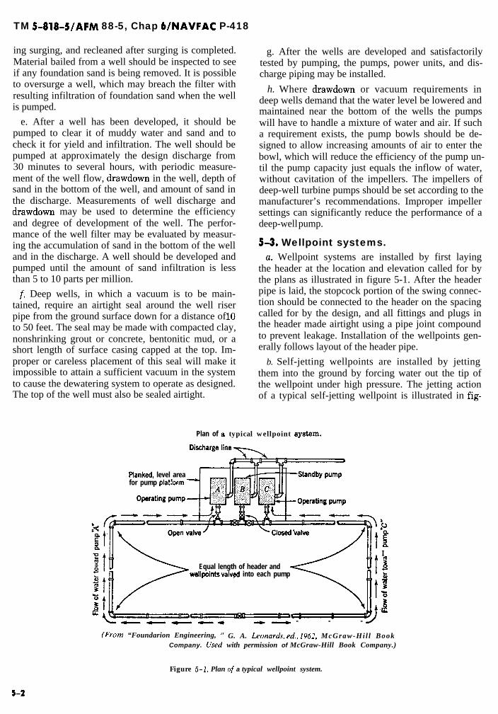
TM 5-818-5/AFM 88-5, Chap 6/NAVFAC P-418
ing surging, and recleaned after surging is completed.Material bailed from a well should be inspected to seeif any foundation sand is being removed. It is possibleto oversurge a well, which may breach the filter withresulting infiltration of foundation sand when the wellis pumped.
e. After a well has been developed, it should bepumped to clear it of muddy water and sand and tocheck it for yield and infiltration. The well should bepumped at approximately the design discharge from30 minutes to several hours, with periodic measure-ment of the well flow, drawdown in the well, depth ofsand in the bottom of the well, and amount of sand inthe discharge. Measurements of well discharge anddrawdown may be used to determine the efficiencyand degree of development of the well. The perfor-mance of the well filter may be evaluated by measur-ing the accumulation of sand in the bottom of the welland in the discharge. A well should be developed andpumped until the amount of sand infiltration is lessthan 5 to 10 parts per million.
f. Deep wells, in which a vacuum is to be main-tained, require an airtight seal around the well riserpipe from the ground surface down for a distance of 10to 50 feet. The seal may be made with compacted clay,nonshrinking grout or concrete, bentonitic mud, or ashort length of surface casing capped at the top. Im-proper or careless placement of this seal will make itimpossible to attain a sufficient vacuum in the systemto cause the dewatering system to operate as designed.The top of the well must also be sealed airtight.
g. After the wells are developed and satisfactorilytested by pumping, the pumps, power units, and dis-charge piping may be installed.
h. Where drawdown or vacuum requirements indeep wells demand that the water level be lowered andmaintained near the bottom of the wells the pumpswill have to handle a mixture of water and air. If sucha requirement exists, the pump bowls should be de-signed to allow increasing amounts of air to enter thebowl, which will reduce the efficiency of the pump un-til the pump capacity just equals the inflow of water,without cavitation of the impellers. The impellers ofdeep-well turbine pumps should be set according to themanufacturer’s recommendations. Improper impellersettings can significantly reduce the performance of adeep-well pump.
5-3. Wellpoint systems.u. Wellpoint systems are installed by first laying
the header at the location and elevation called for bythe plans as illustrated in figure 5-1. After the headerpipe is laid, the stopcock portion of the swing connec-tion should be connected to the header on the spacingcalled for by the design, and all fittings and plugs inthe header made airtight using a pipe joint compoundto prevent leakage. Installation of the wellpoints gen-erally follows layout of the header pipe.
b. Self-jetting wellpoints are installed by jettingthem into the ground by forcing water out the tip ofthe wellpoint under high pressure. The jetting actionof a typical self-jetting wellpoint is illustrated in fig-
Plan of a typical wellpoint ay8te.m.
Pianked, level areafor pump platbrm
L‘a’E2I
Equal length of header ands
wellpoints valvd into each pumps2E0
4
- - -
(From “Foundarion Engineering, ” G. A. L.eonards, ed., 1962, McGraw-Hil l BookCompany. Used with permission of McGraw-Hill Book Company.)
Figure 5-1. Plan of a typical wellpoint system.
5-2

TM 5-818-5/AFM 88-5, Chap WNAVFAC P-418
ure 5-2. Self-jetting wellpoints can be installed in me-dium and fine sand with water pressures of about 50pounds per square inch. Wellpoints jetted into coarsesand and gravel require considerably more water andhigher water pressures (about 125 pounds per squareinch) to carry out the heavier particles; either a hy-drant or a jetting pump of appropriate size for thepressures and quantities of jetting water required canbe used. The jetting hose, usually 2 to 3 inches in diam-eter, is attached to the wellpoint riser, which is pickedup either by a crane or by hand and held in a verticalposition as the jet water is turned on. The wellpoint isallowed to sink slowly into the ground and is slowlyraised and lowered during sinking to ensure that allfine sand and dirt are washed out of the hole. Careshould be taken to ensure that a return of jet water tothe surface is maintained; otherwise, the point may“freeze” before it reaches grade. If the return of jet wa-ter disappears, the point should be quickly raised untilcirculation is restored and then slowly relowered. Ingravelly soils, it may be necessary to supplement thejet water with a separate air supply at about 125pounds per square inch to lift the gravel to the surface.If filter sand is required around the wellpoint to in-crease its efficiency or prevent infiltration of founda-tion soils, the wellpoints generally should be installed
using a hole puncher and a jet casing to form the holefor the wellpoint and filter. When the wellpoint reach-es grade and before the water is turned off, the twohalves of a swing connection, if used, should be linedup for easy connection when the jet water is turned offand the jetting hose disconnected.
c. Where a wellpoint is to be installed with a filter(i.e. “sanded”), generally the wellpoint should be in-stalled in a hole formed by jetting down a lo- to 12-inch heavy steel casing. The casing may be fitted witha removable cap at the top through which air and wat-er may be introduced. The casing is jetted into theground with a return of air and water along the out-side of the casing. Jetting pressures of 125 pounds persquare inch are commonly used; where resistant strataare encountered, the casing may have to be raised anddropped with a crane to chop through and penetrate tothe required depth. A casing may also be installed us-ing a combination jetting and driving tool, equippedwith both water and air lines, which fits inside the cas-ing and extends to the bottom of the casing. Most ofthe return water from a ‘hole puncher” rises inside thecasing, causing considerably less disturbance of the ad-jacent foundation soils. After the casing is installed toa depth of 1 to 3 feet greater than the length of the as-
Pointed tip of wellpoint withhigh pressure jet stream
(Courtesy of Grly$n Wellpoint Corp.)
Figure 5-2. Selfjetting wellpoint.

TM 5-818-5/AFM 88-5, Chap WNAVFAC P-418
sembled wellpoint, the jet is allowed to run until thecasing is flushed clean with clear water.
d. !l?he wellpoint is placed in the casing, the sand fil-ter tremied or poured in, and the casing pulled. Careshould be taken to center the wellpoint in the casing sothat it is completely surrounded with filter material.Before the wellpoint is connected to the header, itshould be pumped to flush it and the filter and tocheck it for “sanding.” All joints connecting wellpointsto the header should be made airtight to obtain themaximum needed vacuum.
e. Wellpoint pumps, similar to that shown in figure5-3, are used to provide the vacuum and to removewater flowing to the system. To obtain the maximum
possible vacuum, the suction intake of the pumpshould be set level with the header pipe, Wellpointpumps should be protected from the weather by a shel- ‘-ter and from surface water or sloughing slopes byditches and dikes. The discharge pipe should be water-tight and supported independently of the pump.
f. Vacuum wellpoint systems are installed in thesame manner as ordinary wellpoint systems using a jetcasing and filter, except the upper 5 feet of the riser issealed airtight to maintain the vacuum in the filter.
g. Jet-eductor wellpoints are usually installed usinga hole puncher and surrounding the wellpoint and ris-er pipe with filter sand. Jet eductors are connected totwo headers-one for pressure to the eductors and
8
1.2.
i:5.6.
ii:
I6
3 2’4
Centrifugal Pump Volute 9. Air Suction l_ine Wiper Float 16,Cleanout Chamber to Vacuum Pump 17.Screenbox 10. Oischarae Check Valve 18.Suction or Header Connection Il. Vacuum &np Exhaust 13.Wiper Float Drain l_ine 12. Oil Reclaimer for Vacuum Pump 20.Scrubber Float Chamber 13. Discharge Connection 21.Wiper Float Chamber 14. FiexIble Coupling 2.2.Air Vent Valve 15. Engine 23.
Cooling Water l.ine for Vacuum PumpBelt GuardVacuum Pump PulleyNT71-4 Rotary-Type Vacuum PumpVacuum Pump Rocker-Type BaseVacuum Pump Exhaust ThermometerVacuum Pump Oil Supply LinesOil Dripper/Lubricator for VxuwnPump
figure 5-3. Characteristic parts of L uAlpoilztpwnp.

TM 5-818-5/AFM 88-5, Chap WNAVFAC P-418
another for return flow from the eductors and thewellpoints back to the recirculation tank and pressurePumP*
5-4. Vertical sand drains. Vertical sand drainscan be installed by jetting a 12- to 18-inch casing intothe soil to be drained; thoroughly flushing the casingwith clear water; filling it with clean, properly gradedfilter sand; and pulling the casing similar to installing“sanded” wellpoints. It is preferable to place the filtersand through a tremie to prevent segregation, whichmay result in portions of the filter being too coarse tofilter fine-grained soils and too fine to permit verticaldrainage. Sand drains should penetrate into the under-lying pervious aquifer to be drained by means of wellsor wellpoints.
5-5. cutoff 8.a. Cement and chemical grout curtains.
(1) Cement or chemical grouts are injectedthrough pipes installed in the soil or rock. Generally,pervious soil or rock formations are grouted from thetop of the formation downward. When this procedureis followed, the hole for the grout pipe is first cored ordrilled down to the first depth to be grouted, the groutpipe and packer set, and the first zone grouted. Afterthe grout is allowed to set, the hole is redrilled and ad-vanced for the second stage of grouting, and the aboveprocedure repeated. This process is repeated until theentire depth of the formation has been grouted. Nodrilling mud should be used in drilling holes for groutpipes because the sides of the hole will h plasteredwith the mud and little, if any, penetration of groutwill be achieved.
(2) Mixing tanks and pump equipment for pres-sure injection of cement or chemical grouts vary de-pending upon the materials being handled. Ingredientsfor a grout mix are loaded into a mixing tank equippedwith an agitator and, from there, are pumped to a stor-age tank also equipped with an agitator. Pumps forgrouting with cement are generally duplex, positivedisplacement, reciprocating pumps similar to slushpumps used in oil fields. Cement grouts are highlyabrasive, so the cylinder liners and valves should be ofcase-hardened steel Chemical grouts, because of theirlow viscosity and nonabrasive nature, can be pumpedwith any type of pump that produces a satisfactorypressure. Grout ptunp capacities commonly rangefrom 20 to 100 gallons per minute at pressures rang-ing from 0 to 500 pounds per square inch. The maxi-mum grout pressure used should not exceed about 1pound per square inch times the depth at which thegrout is being injected.
(3) The distribution system for grouting may beeither of two types: a single-line system or a recircu-lating system. Because of segregation that may de-
velop in the pressure supply line from the pump to thegrout injection pipe, the line must occasionally beflushed to ensure that the grout being pumped into theformation is homogeneous and has the correct viscos-ity. The grout in a single-line system is flushedthrough a blowoff valve onto the ground surface andwasted. A recirculating system has a return line to thegrout storage tank so that the grout is constantly be-ing circulated through the supply line, with a tap off tothe injection pipe where desired.
(4) Additional information on grouting is con-tained in TM 5-818-6.
b. Slurry walls.(1) Slurry cutoff trenches can be dug with a
trenching machine, backhoe, dragline, or a clam buck-et, typically 2 to 5 feet wide. The walls of the trenchare stabilized with a thick bentonitic slurry until thetrench can be backfilled. The bentonitic slurry is bestmixed at a central plant and delivered to the trench intrucks or pumped from slurry ponds. The trench’is car-ried to full depth by excavation through the slurry,with the trench being maintained full of slurry by theaddition of slurry as the trench is deepened and ex-tended.
(2) With the trench open over a limited length andto full depth, cleaning of the slurry is commenced inorder to remove gravelly or sandy soil particles thathave collected in the slurry, especially near the bottomof the trench. Fair cleanup can be obtained using aclamshell bucket; more thorough cleaning can be ob-tained by airlifting the slurry to the surface for circu-lation through desanding units. Cleaning of the slurrymakes it less viscous and ensures that the slurry willbe displaced by the soilbentonite backfill. After clean-ing the “in-trench” slurry, the trench is generally back-filled with a well-graded mix of sand-clay-gravel andbentonite slurry with a slump of about 4 to 6 inches.The backfill material and slurry may be mixed eitheralong and adjacent to the trench or in a central mixingplant and delivered to the trench in trucks.
(3) The backfill is introduced at the beginning ofthe trench so as to displace the slurry toward the ad-vancing end of the trench. In the initial stages of back-fill, special precautions should be taken to ensure thatthe backfill reaches the bottom of the trench and thatit assumes a proper slope (generally 1V on 5H to 1V on1OH). In order to achieve this slope, the first backfillshould be placed by clamshell or allowed to flow downan inclined ramp, dug at the beginning end of thetrench. As the surface of the backfill is built up to thetop of the trench, digging the trench resumes as shownin figure 5-4. As the backfill is bulldozed into the backof the trench, it flows down the sloped face of the al-ready placed backfill, displacing slurry as it advances.Proper control of the properties of the slurry and back-
s-5

TM 5-818-5/AFM 88-5, Chap 6/NAVFAC P-418
fill is required to ensure that the slurry is not trappedwithin the backfill.
(4) The backfill should be placed continuously asthe trench is advanced. By so doing, sloughing of thetrench walls will be minimized, and the amount of ben-tonitic slurry required kept to a minimum. The level ofthe slurry in the trench should be maintained at least 5feet above the groundwater table. Care should be tak-en to control the density and viscosity of the bentoni-tic slurry as required by the design. To minimize wast-age of bentonitic slurry, it may be necessary to screenout sand and gravel in order to reuse the slurry. (Con-struction techniques are still being developed,)
(5) The toe of the backfill slope should be keptwithin 50 to 150 feet of the leading edge of the trenchto minimize the open length of the slurry-supportedtrench. During placement operations, excavation andcleaning operations proceed simultaneously ahead ofthe advancing backfill. (It should be noted that be-cause of the geometric constraints set by the backfillslope, the amount of open trench length supported byslurry is a function of the depth of the trench. For ex-ample, if the trench is 100 feet deep and the backfillslope is 1V on 8H, the open length will be about 900 to950 feet-800 feet along the slope of the backfill faceplus 100 to 150 feet from the backfill toe to the lead-ing edge of the trench.)
(6) When the trench is complete and the backfilloccupies the entire trench, a compacted clay cap is nor-mally placed over the trench. Key steps in this con-struction sequence involve the mixing of the bento-nite-water slurry, excavation and stabilization of thetrench, cleaning of the slurry, mixing of the soil-bento-nite backfill, displacement of the slurry by the back-fill, and treatment of the top of the trench. Each ofthese items must be covered in the specifications.
LEADING EDGE OFTRENCH EXCAVATION
c. Steel sheet piling. Steel sheet pile cutoffs are con-structed employing the same general techniques asthose used for driving steel sheet piles. However, pre-cautions should be taken in handling and driving sheetpiling to ensure that the interlocks are tight for thefull depth of the piling and that all of the sheets aredriven into the underlying impermeable stratum at alllocations along the sheet pile cutoff. Methods andtechniques for driving steel sheet piling are describedin numerous referencestm this subject.
d. Freezing. Freezing the soil around a shaft or tun-nel requires the installation of pipes into the soil andcirculating chilled brine through them. These pipesgenerally consist of a 2-inch inflow pipe placed in a6-inch closed-end “freezing” pipe installed in theground by any convenient drilling means. Two headersare requried for a freezing installation: one to carrychilled brine from the refrigeration plant and the oth-er to carry the return flow of refrigerant. The refriger-ation plant should be of adequate capacity and shouldinclude standby or auxiliary equipment to maintain acontinuous operation.
5-6. Piezometers.CL Instcdluticm. Piezometers are installed to deter-
mine the elevation of the groundwater table (gravityor artesian) for designing and evaluating the perfor-mance of a dewatering system. For most dewateringapplications, commercial wellpoints or small screensare satisfactory as piezometers. The selection of well-point or screen, slot size,‘need for filter, and method ofinstallation is the same for piezometers as for dewater-ing wellpoints, Holes for the installation of piezomet-ers can be advanced using continuous flight auger witha hollow stem plugged at the bottom with a removable
MOVEMENTOF BACKFILLING OPERATION
BENTONITE-WATER SLMi?f
.___-_____---_-_--------------,___________________________________________________________,~~ERV,~“~ LA~ER~-_-_-_-_-_-_---_-------_-_-=-----------------------~-~-~-~-~-~-~-~-~-~-~-~-~----------------____________________-_-_-_--------------------~~.___-_-__-_-_---------~
U.S. Army Corps of Engineers
figure 5-4. InstaUation of a slurry cutoff trench.
5-6

TM S-818-5/AFM 88-5, Chap WNAVFAC p-418
plug, augering with more or less simultaneous installa-tion of a casing, or using rotary wash-boring methods.The hole for a piezometer should be kept filled withwater or approved drilling fluid at all times. Bentoni-tic drilling mud should not be used; however, an organ-ic type of drilling fluid, such as Johnson’s Revert orequivalent, may be used if necessary to keep thedrilled hole open. Any auger used in advancing thehole should be withdrawn slowly from the hole so as tominimize any suction effect caused by its removal.When assembling piezometers, all fittings should betight and sealed with joint compound so that waterlevels measured are those actually existing at the loca-tion of the wellpoint screen. Where the water table indifferent pervious formations is to be measured, theriser pipe from the piezometer tip must be sealed fromthe top of the screen to the ground surface to preservethe isolation of one stratum from another and to ob-tain the true water level in the stratum in which thepiezometer is set. Such piezometers may be sealed bygrouting the hole around the riser with a nonshrinkinggrout of bentonite, cement, and fly ash or other suita-ble admixture. Proportions of 1 sack of cement and 1gallon of bentonite to 10 gallons of water have beenfound to be a suitable grout mix for this purpose. Flyash can be used to replace part of the cement to reduceheat of hydration, but it does reduce the strength ofthe grout. The tops of piezometer riser pipes should bethreaded and fitted with a vented cap to keep dirt anddebris from entering the piezometer and to permit thewater level in the piezometer to adjust to any changesin the natural water table.
(1) Hollow-stem auger method.(a) After the hole for the piezometer is advanced
to grade, 1 to 2 feet below the piezometer tip, or afterthe last sample is taken in a hole to receive a piezomet-er, the hollow-stem auger should be flushed clean withwater and the plug reinserted at the bottom of the au-ger. The auger should then be slowly raised to the ele-vation that the piezometer tip is to be installed. At thiselevation, the hollow stem should be filled with cleanwater and the plug removed. Water should be added tokeep the stem full of water during withdrawal of theplug. The hole should then be sounded to determinewhether or not the hollow stem is open to the bottomof the auger. If material has entered the hollow stemof the auger, the hollow stem should be cleaned byflushing with clear water, or fresh Johnson’s Revert ore_quivalent drilling fluid if necessary to stabilize thebottom of the hole, through a bit designed to deflectthe flow of water upward, until the discharge is free ofsoil particles. The piezometer screen and riser shouldthen be lowered to the proper depth inside the hollowstem and the filter sand placed. A wire spider shouldbe attached to the bottom of the piezometer screen to
center the piezometer screen in the hole in which it isto be placed.
(b) The filter sand should be poured down thehollow stem around the riser at a rate (to be deter-mined in the field) which will ensure a continuous flowof filter sand that will keep the hole below the augerfilled as the auger is withdrawn, Withdrawal of the au-ger and filling the space around the piezometer tip andriser with filter sand should continue until the hole isfilIed to a point 2 to 5 feet above the top of the piezom-eter screen. Above this elevation, the space around theriser pipe may be filled with any clean uniform sandup to the top of the particular sand stratum in whichthe piezometer is being installed but not closer than 10feet of the ground surface. An impervious grout sealshould then be placed from the top of the sand backfillto the ground surface.
(2) Casing method. The hole for a piezometer maybe formed by setting the casing to an elevation 1 to 2feet deeper than the elevation of the piezometer tip.The casing may be set by a combination of rotary drill-ing and driving the casing. The casing should be keptfilled with water, or organic drilling fluid, if neces-sary, to keep the bottom of the hole from ‘blowing.”After the casing has been set to grade, it should beflushed with water or fresh drilling fluid until clear ofany sand. The piezometer tip and riser pipe shouldthen be installed and a filter sand, conforming to thatspecified previously, poured in around the riser at arate (to be determined in the field) which will ensure acontinuous flow of filter sand that will keep the spacearound the riser pipe and below the casing filled as thecasing is withdrawn without “sand-locking” the casingand the riser pipe. Placement of the filter sand andwithdrawal of the casing may be accomplished in stepsas long as the top of the filter sand is maintained abovethe bottom of the casing but not so much as to “sand-lock” the riser pipe and casing. Filling the spacearound the piezometer tip and riser with filter andshould continue until the hole is filled to a point 2 to 5feet above the top of the piezometer screen. An imper-vious grout seal should then be placed from the tok: ofthe sand backfill to the ground surface.
(3) Rotary method. The hole for a piezometer maybe advanced by the hydraulic rotary method usingwater or an organic drilling fluid. After the hole hasbeen advanced to a depth of 1 or 2 feet below the pie-zometer tip elevation, it should be flushed with clearwater or clean drilling fluid, and the piezometer, filtersand, sand backfill, and grout placed as specified abovefor the casing method, except there will be no casing topull.
b. Development and testing. The piezometer shouldbe flushed with clear water and pumped after installa-tion and then checked to determine if it is functioning
5-7

TM 5-818-S/AFM 88-5, Chap WNAVFAC P-418
properly by filling with water and observing the rateof fall. A lo-foot minimum positive head should bemaintained in the piezometer following breakdown ofthe drilling fluid. After at least 30 minutes haveelapsed, the piezometer should be flushed with clearwater and pumped. For the piezometer to be consid-ered acceptable, it should pump at a rate of at least 2gallons per minute, or when the piezometer is filledwith water, the water level should fall approximatelyhalf the distance to the groundwater table in a timeslightly less than the time given below for various
types of soil:
Type of Soil inWhich Piezometer
Screen Is Set
Period ofObservation
minutes
ApproximateTime of
50 Perce7zt Failminutes
Sandy silt (>50% silt)Silty sand (<50% silt,
30 30
>12% silt) 10 5Fine sand 5 1
If the piezometer does not function properly, it will bedeveloped by air surging or pumping with air if neces-sary to make it perform properly.
5-8
TM 5-818-5/AFM 88-5, Chap WNAVFAC P-418
CHAPTER 6
OPERATION AND PERFORMANCE CONTROL
6-1. General. The success of a dewatering opera-tion finally hinges on the proper operation, mainte-nance, and control of the system. If the system is notoperated and maintained properly, its effectivenessmay soon be lost. After a dewatering or pressure reliefsystem has been installed, a full-scale pumping testshould be made and its performance evaluated for ade-quacy or need for any modification of the system. Thistest and analysis should include measurement of theinitial water table, pump discharge, water table in ex-cavation, water table in wells or vacuum in header sys-tem, and a comparison of the data with the original de-sign.
6-2. Operation.a. Wellpoint systems.
(1) The proper performance of a wellpoint systemrequires continuous maintenance of a steady, high vac-uum. After the system is installed, the header line andall joints should be tested for leaks by closing allswing-joint and pump suction valves, filling the headerwith water under a pressure of 10 to 15 pounds persquare inch, and checking the line for leaks. The nextstep is to start the wellpoint pump with the pump suc-tion valve closed. The vacuum should rise to a steady25 to 27 inches of mercury. If the vacuum on the pumpis less than this height, there must be air leaks or wornparts in the pump itself. If the vacuum at the pump issatisfactory, the gate valve on the suction side of thepump may be opened and the vacuum applied to theheader, with the wellpoint swing-joint valves stillclosed. If the pump creates a steady vacuum of 25inches or more in the line, the header line may be con-sidered tight. The swing-joint valves are then openedand the vacuum is applied to the wellpoints. If a low,unsteady vacuum develops, leaks may be present inthe wellpoint riser pipes, or the water table has beenlowered to the screen in some wellpoints so that air isentering the system through one or more wellpointscreens. One method of eliminating air entering thesystem through the wellpoints is to use a riser pipe 25feet or more in length. If the soil formation requiresthe use of a shorter riser pipe, entry of air into the sys-tem can be prevented by partially closing the mainvalve between the pump and the header or by adjust-ing the valves in the swing connections until air enter-ing the system is stopped. This method is commonlyused for controlling air entry and is known as tuning
the system; the pump operator should do this daily.(2) A wellpoint leaking air will frequently cause
an audible throbbing or bumping in the swing-jointconnection, which may be felt by placing the hand onthe swing joint. The throbbing or bumping is caused byintermittent charges of water hitting the elbow at thetop of the riser pipe. In warm weather, wellpoints thatare functioning properly feel cool and will sweat due tocondensation in a humid atmosphere. A wellpoint thatis not sweating or that feels warm may be drawing airthrough the ground, or it may be clogged and not func-tioning. Likewise, in very cold weather, properly func-tioning wellpoints will feel warm to the touch of thehand compared with the temperature of the atmos-phere. Vacuum wellpoints disconnected from theheader pipe can admit air to the aquifer and may af-fect adjacent wellpoints. Disconnected vacuum well-points with riser pipes shorter than 25 feet should becapped.
(3) Wellpoint headers, swing connections, andriser pipes should be protected from damage by con-struction equipment. Access roads should cross headerlines with bridges over the header to prevent damageto the headers or riser connections and to provide ac-cess for tuning and operating the system.
b. Deep wells. Optimum performance of a deep-wellsystem requires continuous uninterrupted operation ofall wells. If the pumps produce excessive drawdownsin the wells, it is preferable to regulate the flow fromall of the wells to match the flow to the system, ratherthan reduce the number of units operating and thuscreate an uneven drawdown in the dewatered area.The discharge of the wells may be regulated by vary-ing the pump speed (if other than electric power isused) or by varying the discharge pressure head bymeans of a gate valve installed in the discharge lines.Uncontrolled discharge of the wells may also produceexcessive drawdowns within the well causing undesira-ble surging and uneven performance of the pumps.
c. Pumps. Pumps, motors, and engines should al-ways be operated and maintained in accordance withthe manufacturer’s directions. All equipment shouldbe maintained in first-class operating condition at alltimes. Standby pumps and power units in operatingconditions should be provided for the system, as dis-cussed in chapter 4. Standby equipment may be re-quired to operate during breakdown of a pumping unit
6-1

TM 5-818-5/AFM 88-5, Chap 6/NAVFAC P-418
or during periods of routine maintenance and oilchange of the regular dewatering equipment. Allstandby equipment should be periodically operated toensure that it is ready to function in event of a break-down of the regular equipment. Automatic starters,clutches, and valves may be included in the standbysystem if the dewatering requirements so dictate. Sig-nal lights or warning buzzers may be desirable to indi-cate, respectively, the operation or breakdown of apumping unit. If control of the groundwater is criticalto safety of the excavation or foundation, appropriateoperating personnel should be on duty at all times.Where gravity flow conditions exist that allow the wa-ter table to be lowered an appreciable amount belowthe bottom of the excavation and the recovery of thewater table is slow, the system may be pumped onlypart time, but this procedure is rarely possible or de-sirable. Such an operating procedure should not be at-tempted without first carefully observing the rate ofrise of the groundwater table at critical locations inthe excavations and analyzing the data with regard toexisting soil formations and the status of the excava-tion.
d. Surface water control. Ditches, dikes, sumps, andpumps for the control of surface water and the protec-tion of dewatering pumps should be maintainedthroughout construction of the project. Maintenanceof ditches and sumps is of particular importance. Silt-ing of ditches may cause overtopping of dikes and seri-ous erosion of slopes that may clog the sumps andsump pumps. Failure of sump pumps may result inflooding of the dewatering equipment and completebreakdown of the system. Dikes around the top of anexcavation to prevent the entry of surface watershould be maintained to their design section and gradeat all times. Any breaks in slope protection should bepromptly repaired.
6-3. Control and evaluation of perform-ance. After a dewatering or groundwater controlsystem is installed, it should be pump-tested to checkits performance and adequacy. This test should includemeasurement of initial groundwater or artesian watertable, drawdown at critical locations in the excavation,flow from the system, elevation of the water level inthe wells or vacuum at various points in the header,and distance to the “effective” source of seepage, ifpossible. These data should be analyzed, and if condi-tions at the time of test are different than those forwhich the system was designed, the data should be ex-trapolated to water levels and source of seepage as-sumed in design. It is important to evaluate the systemas early as possible to determine its adequacy to meetfull design requirements. Testing a dewatering systemand monitoring its performance require the installa-tion of piezometers and the setting up of some means
for measuring the flow from the system or wells. Pres-sure and vacuum gages should also be installed at thepumps and in the header lines. For multistage well-point systems, the installation and operation of thefirst stage of wellpoints may offer an opportunity tocheck the permeability of the pervious strata, radius ofinfluence or distance to the source of seepage, and thehead losses in the wellpoint sytem. Thus, from obser-vations of the drawdown and discharge of the firststage of wellpoints, the adequacy of the design for low-er stages may be checked to a degree.
a. Piezometers. The location of piezometers shouldbe selected to produce a complete and reliable pictureof the drawdown produced by the dewatering system.Examples of types of piezometers and methods of in-stallation are given in paragraphs G-546) andG-6h(2) of Appendix G. Piezometers should be locatedso they will clearly indicate whether water levels re-quired by specifications are attained at significant lo-cations. The number of piezometers depends on thesize and configuration of the excavation and the dewa-tering system. Normally, three to eight piezometersare installed in large excavations and two or three insmaller excavations. If the pervious strata are strati-fied and artesian pressure exists beneath the excava-tion, piezometers should be located in each significantstratum. Piezometers should be installed at the edge ofand outside the excavation area to determine theshape of the drawdown curve to the dewatering sys-tem and the effective source of seepage to be used inevaluating the adequacy of the system. If recharge ofthe aquifer near the dewatering system is required toprevent settlement of adjacent structures, controlpiezometers should be installed in these areas. Wherethe groundwater is likely to cause incrustation of wellscreens, piezometers may be installed at the outer edgeof the filter and inside the well screen to monitor thehead loss through the screen as time progresses. Inthis way, if a significant increase in head loss is noted,cleaning and reconditioning of the screens should beundertaken to improve the efficiency of the system.Provisions for measuring the drawdown in the wells orat the line of wellpoints are desirable from both an op-eration and evaluation standpoint.
b. Flow measurements. Measurement of flow from adewatering system is desirable to evaluate the per-formance of the system relative to design predictions.Flow measurements are also useful in recognizing anyloss in efficiency of the system due to incrustation orclogging of the wellpoints or well screens. Appendix Fdescribes the methods by which flow measurementscan be made.
c. Operational records. Piezometers located withinthe excavated area should be observed at least once aday, or more frequently, if the situation demands, to
6-2

ensure that the required drawdown is being main-tained. Vacuum and gages (revolutions per minute) on
- pumps and engines should be checked at least everyfew hours by the operator as he makes his rounds.Piezometers located outside the excavated area, anddischarge of the system, may be observed less fre-quently after the initial pumping test of the completedsystem is concluded. Piezometer readings, flow meas-urements, stages of nearby streams or the elevation of
TM 5-818~5/AFM 88-5, Chap 6/NAVFAC P-418
the surrounding groundwater, and the number of wellsor wellpoints operating should be recorded and plottedthroughout the operation of the dewatering system.The data on the performance of the dewatering systemshould be continually evaluated to detect any irregularfunctioning or loss of efficiency of the dewatering sys-tem before the construction operations are impeded, orthe excavation or foundation is damaged.
-
6-3

TM 5-818-5/AFM 88-5, Chap WNAVFAC P-418
CHAPTER 7
CONTRACT SPECIFICATIONS
7-1. General. Good specifications are essential toensure adequate dewatering and groundwater control.Specifications must be clear, concise, and completewith respect to the desired results, special conditions,inspection and control, payment, and responsibility.The extent to which specifications should specify pro-cedures and methods. is largely dependent upon thecomplexity and magnitude of the dewatering problem,criticality of the dewatering with respect to scheduleand damage to the work, and the experience of theprobable bidders. Regardless of the type of specifica-tion selected, the dewatering system(s) should be de-signed, installed, operated, and monitored in accord-ance with the principles and criteria set forth in thismanual.
7-2. Types of specifications.a. Type A. Where dewatering of an excavation does
not involve unusual or complex features and failure orinadequacy of the system would not adversely affectthe safety of personnel, the schedule, performance ofthe work, foundation for the structure, or the com-pleted work, the specifications should be one of the fol-lowing types:
(1) Type A-l. A brief specification that requiresthe Contractor to assume full responsibility for design,installation, operation, and maintenance of an ade-quate system. (This type should not be used unless theissuing agency has considerable confidence in the Con-tractor’s dewatering qualifications and has the timeand capability to check the Contractor’s proposal andwork.)
(2) Type A-2. A specification that is more de-tailed than type A-l but still requires the Contractorto assume the responsibility for design, installation,operation, and maintenance. (This type conveys moreinformation regarding requirements of design andconstruction than type A-l while retaining the limita-tions described in (1) above.)
b. Type B. Where dewatering or relief of artesianpressure is complex and of a considerable magnitudeand is critical with respect to schedule and damage tothe work, the specifications should be of one of the fol-lowing types:
(1) Type B-l. A specification that sets forth indetail the design and installation of a “minimum” sys-tem that will ensure a basically adequate degree of wa-tering and pressure relief but still makes the Contrac-
tor fully responsible for obtaining the required dewa-tering and pressure relief as proven by a full-scalepumping test(s) on the system prior to start of excava-tion, and for all maintenance, repairs, and operations.
(2) Type B-2. A specification that sets forth indetail the design and installation of a system that hasbeen designed to achieve the desired control of ground-water wherein the Government or Owner assumes fullresponsibility for its initial performance, based on afull-scale pumping test(s), but makes the Contractorresponsible for maintenance and operation except formajor repairs required over and beyond those appro-priate to normal maintenance. (This type of specifica-tion eliminates claims and contingencies commonlyadded to bid prices for dewatering and also ensuresthat the Government gets a dewatering system that ithas paid for and a properly dewatered excavation ifthe system has been designed and its installation su-pervised by qualified and experienced personnel.)
(3) Type B-3. A specification that sets forth thedesired results making the Contractor solely responsi-ble for design, equipment, installation procedures,maintenance, and performance, but requires that theContractor employ or subcontract the dewatering andgrotmdwater control to a recognized company with atleast 5 years, and preferably 10 years, of experience inthe management, design, installation, and operation ofdewatering systems of equal complexity. The specifi-cation should also state that the system(s) must be de-signed by a registered professional engineer recog-nized as an expert in dewatering with a minimum of 5to 10 years of responsible experience in the design andinstallation of dewatering systems. This type of speci-fication should further require submittal of a brief butcomprehensive report for review and approval includ-ing:
(a) A description and profile of the geology, soil,and groundwater conditions and characteristics at thesite.
(b) Design values, analyses, and calculations.(c) Drawings of the complete dewatering sys-
tem(s) including a plan drawing, appropriate sections,pup and pipe capacities and sizes, power system(s),standby power and pumps, grades, filter gradation,surface water control, valving, and disposal of water.
(d) A description of installation and operationalprocedures.
(e) A layout of piezometers and flow measuring
7-1
TM 5-818-5/AFM 88-5, Chap WNAVFAC p-418
devices for monitoring performance of the system(s).(f) A plan and schedule for monitoring perform-
ance of the system(s).(g) A statement that the dewatering system(s)
has been designed in accordance with the principlesand criteria set forth in this mannual.
@) The seal of the designer.(This type of specification should not be used unlessthe Government or Owner has or employs someonecompetent to evaluate the report and design submit-ted, and is prepared t,o insist on compliance with t,hea b o v e , )
7-3. Data to be included in specifica-tions. All data obtained from field investigations re-lating to dewatering or control of groundwater madeat the site of the project should be included with thespecifications and drawings or appended thereto.These data should include logs of borings; soil profiles;results of laboratory tests including mechanical analy-ses, water content of silts and clays, and any chemicalanalyses of the groundwater; pumping tests; ground-water levels in each aquifer, if more than one, as meas-ured by properly installed and tested piezometers, andits variation with the season or with river stages; andriver stages and tides for previous years if available.Borings should not only be made in the immediate vi-cinity of the excavation, but some borings should bemade on lines out to the source of groundwater flow orto the estimated “effective” radius of influence. Suffi-cient borings should be made to a depth that will de-lineate the full thickness of any substrata that wouldhave a bearing on the control of groundwater or unbal-anced uplift pressures. (Additional information onfield investigations and the scope of such are given inchap 3.) It is essential that all field or laboratory testdata be included with the specifications, or referenced,and that the data be accurate. The availability, ade-quacy, and reliability of electric power, if known,should be included in the contract documen& Thesame is true for the disposal o! water to be pumpedfrom the dewatering systems. The location and owner-ship of water wells off the project site that might be ef-fected by lowering the groundwater level should beshown on one of the contract drawings.
7-4. Dewatering requirements and spec-ifications. The section of the specifications relatingt,o dewatering and the control of groundwater shouldbe prepared by a geot,echnical engineer experienced indewatering and in the writing of specifications, in co-operation with the civil designer for the project. Thedewai,ering specifications may be rather general orquite detailed depending upon the type of specificationto be issued as described in paragraph 7-2.
CL. Type A specifications.
(1) If the specification is to be of Types A-l andA-2 described’in paragraph 7-2u(l) and (2), the de-sired results should explicitly specify the level to -which the groundwater and/or piezometric surfaceshould be lowered; give recommended factors of safetyas set forth in paragraph 4-8; require that all perma-nent work be accomplished in the dry and on a stablesubgrade; and advise the Cont,ract,or that he is respon-sible for designing, providing, installing, operating,monitoring, and removing the dewatering system by aplan approved by the Contracting Officer or the Engi-neer. This type of specification should note the limita-tions of groundwater information furnished sinceseepage conditions may exist that were not discoveredduring the field explorat+ion program. It should bemade clear t,hat the Contractor is not relieved of re-sponsibility of controlling and disposing of all water,even though the discharge of t.he dewatering systemrequired to maintain satisfactory conditions in the ex-cavation may be in excess of that indicated by tests oranalyses performed by the Government. This type ofspecification should not only specify the desired re-sults but also require that the Contractor provide ade-quate methods for obtaining them by means of pump-ing from wells, wellpoint systems, cutoffs, grouting,freezing, or any other measures necessary for particu-lar site conditions. The method of payment should alsobe clearly specified.
(2) Prior to the start of excavation the Contractorshould be required to submit for review a proposedmethod for dewatering the excavation, disposing ofthe water, and removing the system, as well as a list ofthe equipment to be used, including standby equip-ment for emergency use. (This plan should be detailedand adapted to site conditions and should provide foraround-the-clock dewatering operation.)
-
(3) Perimeter and diversion ditches and dikesshould be required and maintained as necessary to pre-vent surface water from entering any excavation. Thespecifications should also provide for controlling thesurface water that falls or flows into the excavation byadequate pumps and sumps. Seepage of any waterfrom excavated slopes should be cont.rolled to preventsloughing, and ponding of water in the excavationshould be prevented during construction operations.Any water encountered in an excavation for a shaft ortunnel shall be controlled, before advancing the exca-vation, to prevent sloughing of the walls or “boils” inthe bottom of the excavation or blow-in of the tunnelface, If the flow of water into an excavation becomesexcessive and cannot be controlld by t,he dewateringsystem that the Contractor has installed, excavationshould be halted until satisfactory remedial measureshave been taken. Dewatering of excavations for shafts,tunnels, and lagged open excavations should continuefor the duration of the work to be performed in the ex-
-
7-2

TM 5-818-5/AFM 88-5, Chap WNAVFAC p-418
cavations unless the tunnel or shaft has been securely quirements set forth for type B-3 specifications inlined and is safe from hydrostatic pressure and seep- paragraph 7 -2.age.
(3) The specifications should also require that theContractor’s plan provide for testing the adequacy ofthe system prior to start of excavation and for moni-toring the performance of the system by installing pi-ezometers and means for measuring the dischargefrom the system.
b. Type B specifications.
(1) Types B-l and B-2 specifications (para7-2b(l) and (2)) should set forth not only the requiredresults for dewatering, pressure relief, and surface wa-ter control, but also a detailed list of the materials,equipment, and procedures that are to be used inachieving the desired system(s). The degree of respon-sibility of the Contractor for dewatering should beclearly set forth for specification types B-l and B-2 aspreviously stated in paragraph 7-2, With either typeof specification, the Contractor should be advised thathe or she is responsible for operating and maintainingthe system(s) in accordance with the manufacturer’srecommendation relating to equipment and in accord-ance with good construction practice. The Contractorshould also be advised that he or she is responsible forcorrecting any unanticipated seepage or pressure con-ditions and taking appropriate measures to controlsuch, payment for which would depend upon the typeof specification and terms of payment.
(2) Type B-3 specifications (para 7-2b) should in-clude the basic requirements set forth above for typesA-l and A-2 specifications plus the additional re-
7-5. Measurement and payment.a. Payment when using types A-l and A-2 specifi-
cations is generally best handled by a “lump sum” pay-ment.
b. Payment when using type B- 1 specifications maybe based on a lump sum type, or unit prices may be setup for specific items that have been predesigned andspecified with lump sum payment for operational andmaintenance costs,
c. Payment when using type B-2 specifications isgenerally on the basis of various unit prices of suchitems as wells, pumps, and piping, in keeping with nor-mal payment practioes for specified work. Operationfor maintenance and repairs generally should be set upas a lump sum payment with partial payment in ac-cordance with commonly accepted percentages ofwork completed,
d. Payment when using type B-3 specificationswould generally be based on a lump sum type of pay-ment.
e. Payment for monitoring piezometers and flowmeasuring devices is generally made in keeping withthe method of payment for the various types of dewa-tering specifications described above,
7-6. Examples of dewatering specifica-tions. Examples of various types of specifications de-scribed in paragraph -72, based on specifications ac-tually issued and accomplished in practice, are includ-ed in appendix G .
7-3

TM 5-815-SIAFM 88-5, Chap 6lNAVFACP-418
APPENDIX AREFERENCES
-- Govemmmt Publicatim
Department of DefenseMilitary Standard
H MIL-STD-619B Unified Soil Classification System for Roads, Airfields,Embankments, and Foundations
Depahnents of the Army and th,e Air ForceTM 5-813-l/AFM 88-3, Chap. 7 Soils and Geology: Procedures for Foundation Designs
of Buildings and Other Structures (Except HydraulicsStructures)
TM 54134/AFM 88-5, Chap. 5 Soils and Geology: Backfill for Subsurface StructuresTM 5-818-6/AFM 38-32 Grouting Methods and Equipment
Department of the Navy
tiNAVFAC DM7.1 Soil MechanicsNAVFAC DM7.3 Deep Stabilization and Grouting
Nongovernment PublicationsAmerican Society for Testing and Materials (ASTM), 1916 Race Street, Philadelphia, PA 19103
4 A 108431 Steel Bars, Carbon, Cold-Finished, Standard QualityA74343 Castings, Iron-Chromium, Iron-Chromium-Nickel,
Nickel-Base, Corrosion Resistant for GeneralApplication
BIBLIOGRAPHY
B NAVAC DM7.2 Foundations and Earth Structures
-
Change 1 A - l
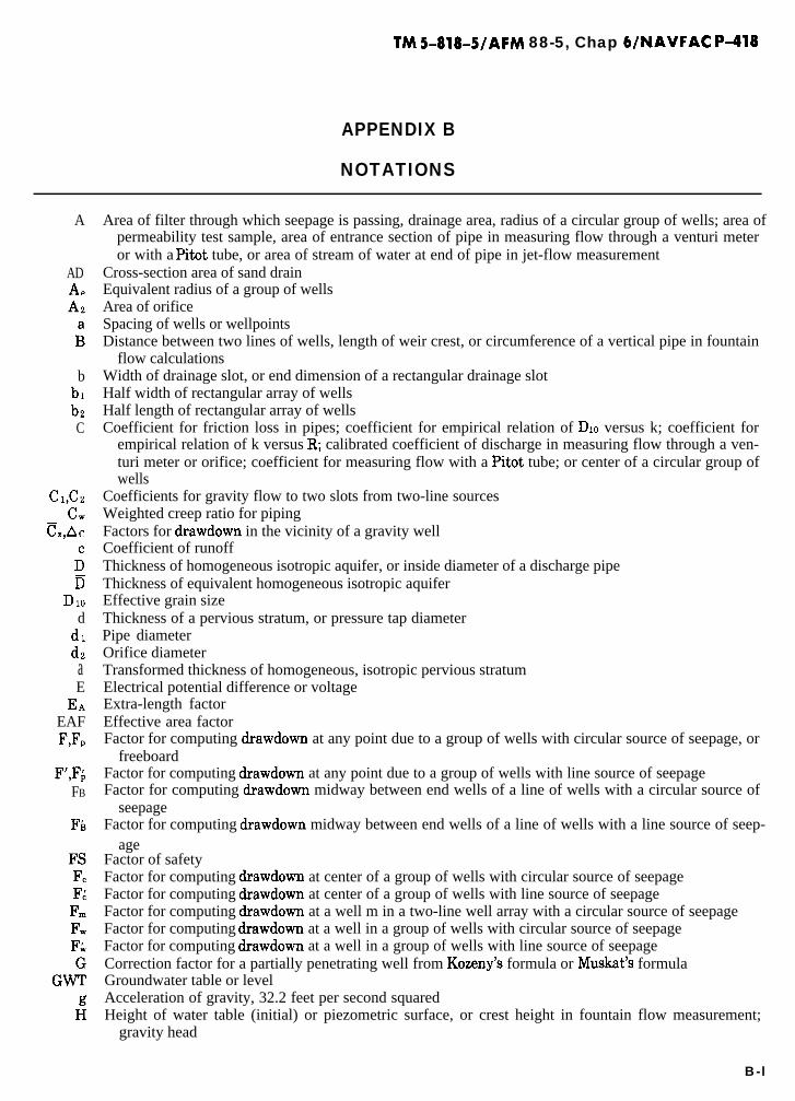
TM 5-818-5/AFM 88-5, Chap WNAVFAC ~418
APPENDIX B
NOTATIONS
A Area of filter through which seepage is passing, drainage area, radius of a circular group of wells; area ofpermeability test sample, area of entrance section of pipe in measuring flow through a venturi meteror with a Pitot tube, or area of stream of water at end of pipe in jet-flow measurement
ADAeAZ
ii
Cross-section area of sand drainEquivalent radius of a group of wellsArea of orificeSpacing of wells or wellpointsDistance between two lines of wells, length of weir crest, or circumference of a vertical pipe in fountain
flow calculationsb Width of drainage slot, or end dimension of a rectangular drainage slot
bl Half width of rectangular array of wellsb2 Half length of rectangular array of wellsC Coefficient for friction loss in pipes; coefficient for empirical relation of DIO versus k; coefficient for
empirical relation of k versus R; calibrated coefficient of discharge in measuring flow through a ven-turi meter or orifice; coefficient for measuring flow with a Pitot tube; or center of a circular group ofwells
Cl,C2
CLC=,Ac
;D
DIOd
dldzaEEA
EAFF,Fp
Coefficients for gravity flow to two slots from two-line sourcesWeighted creep ratio for pipingFactors for drawdown in the vicinity of a gravity wellCoefficient of runoffThickness of homogeneous isotropic aquifer, or inside diameter of a discharge pipeThickness of equivalent homogeneous isotropic aquiferEffective grain sizeThickness of a pervious stratum, or pressure tap diameterPipe diameterOrifice diameterTransformed thickness of homogeneous, isotropic pervious stratumElectrical potential difference or voltageExtra-length factorEffective area factorFactor for computing drawdown at any point due to a group of wells with circular source of seepage, or
freeboardF’,F;
FB
Factor for computing drawdown at any point due to a group of wells with line source of seepageFactor for computing drawdown midway between end wells of a line of wells with a circular source of
seepageFactor for computing drawdown midway between end wells of a line of wells with a line source of seep-
ageFactor of safetyFactor for computing drawdown at center of a group of wells with circular source of seepageFactor for computing drawdown at center of a group of wells with line source of seepageFactor for computing drawdown at a well m in a two-line well array with a circular source of seepageFactor for computing drawdown at a well in a group of wells with circular source of seepageFactor for computing drawdown at a well in a group of wells with line source of seepageCorrection factor for a partially penetrating well from Kozeny’s formula or Muskat’s formulaGroundwater table or levelAcceleration of gravity, 32.2 feet per second squaredHeight of water table (initial) or piezometric surface, or crest height in fountain flow measurement;
gravity head
B-l

TM 5-818-5/AFM 88-5, Chap WNAVFAC P-418
Drawdown or head differential, or residual drawdown after a pump testDrawdown expressed as Hz-Hz0Head dimension in the measurement of flow with a Parshall flumeAverage head loss in header pipe to pump intakeFriction head loss in screen entrance or filter and screen entranceFriction head loss in riser pipe and connectionsFriction head loss in well screenVelocity head loss in wellTotal hydraulic head loss in well or wellpointDistance from bottom of sheet pile or cutoff wall to impervious boundaryHead at a specific point P, head on permeability test sample in constant head permeability test; final
head on permeability test sample in falling head permeability test; pressure drop across an orifice; ob-served head on crest in weir flow measurement; or head at a specific time during a pump test
Height of free discharge above water level in a gravity wellHead at center of a group of wellsMaximum head landward from a drainage slot or line of wells, or maximum head between two slots or
lines of wellsHead in an artesian drainage slot, average head at a line of wells, or height of bottom of excavation in
computing the creep ratioHead midway between wells, or height of mercury for pipe orifice flow measurementHead in a gravity drainage slot or at equivalent drainage slot simulating a line of wellpoints or sand
drains, or initial head on permeability test sample in the falling heat permeability testHead at point PHeight of free discharge above water level in drainage slotVelocity head in measuring flow with a Pitot tubeHead at well, wellpoint, or sand drainWetted screen lengthHead in a wellpoint that can be produced by the vacuum of a wellpoint pumpElectric current or rate of flow
-
Hydraulic gradient of seepage, well number, intensity of rainfallElectrical gradient between electrodesDrawdown at any wellConstant used in jet-flow calculationsCoefficient of permeability of homogeneous isotropic aquiferTransformed coefficient of permeabilityCoefficient of permeability for the flow of airVertical coefficient of permeability of a sand drainCoefficient of electroosmotic permeabilityEffective permeability of transformed aquiferHorizontal coefficient of permeabilityVertical coefficient of permeabilityDistance from drainage slot, well, or line of wells or wellpoints to the effective source of seepage, length
of permeability test sample, or seepage length through which Ah acts in determining a seepage gradi-ent
Distance from drainage slot to change from artesian to gravity flowDistance from well j to source of seepageHalf the distance between two parallel drainage slots or lines of wells; long dimension of a rectangular
drainage slot, or number of strata penetrated by a well in calculating effective well screen penetrationW
Height of pump intake above base of aquiferMean sea levelNumber of equipotential drops in a flow netNumber of flow channels in a flow netNumber of wells in system or group, or porosity, number of strata in an aquifer for transformed section
calculations, or number of concentric rings in measuring flow with a Pitot tubeNumber of equipotential drops from seepage exit to point P
_

TM 5-818-5/AFM 88-5, Chap WNAVFAC ~418
RRiRj
rr’ri
rij
rwrti
S
S’Si
SijSY
T’tt
t’t”to
;
Point at which head is computed, or factor for drawdown in the vicinity of a gravity wellMean absolute pressure inflow systemAbsolute atmospheric pressureAbsolute air pressure at line of vacuum wellsRate of flow to a fully penetrating drainage slot per unit length of slot, capacity, or rate of pumping, or
rate of surface water runoffRate of flow of airRated capacity of vacuum pump at atmospheric pressureRate of flow to a sand dramFlow to well in an electroosmotic drainage systemTotal surface water pump capacityRate of flow to a partially penetrating drainage slot per unit length of slotTotal flow to a wellpoint systemTotal flow to a dewatering systemFlow to a well or wellpointFlow to an observation wellFlow to well iFlow to well jFlow to a partially penetrating artesian wellRate of flow, or flow per unit length of section flow netLimiting flow into a filter or well screenRadius of influence of well, rainfall for assumed storm, or ratio of entrance to throat diameter in meas-
uring flow through a venturi meterDistance from well to change from artesian to gravity flowRadius of influence of well iRadius of influence of well jDistance from well to point P, or distance from a test well to an observation piezometerDistance from image well to point PDistance from well i to point PDistance from well 1 to well jRadius (effective) of a wellRadius (effective) of well jCoefficient of storage, the volume of water an aquifer will release from (or take into) storage per unit of
surface area per unit change in head. (For urtesiun aquifers, S is equal to the water forced from stor-age by compression of a column of the aquifer by the additional load created by lowering the artesianpressure in the aquifer by pumping or drainage. For gruuity flow aquifers, S is equal to the specificyield of the material being dewatered plus the water forced from the saturated portion of the aquiferby the increased surcharge caused by lowering the groundwater table.)
Extrapolated S value used in computations for nonequilibrium gravity flowDistance from point P to image well iDistance from image well 1 to well jSpecific yield of aquifer (volume of water that can h drained by gravity from a saturated unit volume of
material)Height of bottom of well above bottom of aquiferDuration of rainfall, coefficient of transmissibility in square feet per minute (the coefficient of perme-
ability k multiplied by the aquifer thickness D), or thickness of less pervious strata overlying a morepervious stratum
Coefficient of transmissibility in gallons per day per foot widthDepth of water in well, or elapsed pumping timeTime for cone of drawdown to reach an impermeable boundary or a source of seepageElapsed pumping time since pump startedElapsed time since pump stoppedTime at zero drawdown or at start of pump testArgument of W(u), a well functionVolume of water in permeability test, volume of sample in specific yield test, velocity, or vacuum at
pump intake
B-3

TM 5-818-5/AFM 88-5, Chap WNAVFAC P-418
Volume of sump storageVolume of surface water runoffVelocity at center of concentric rings of equal area in measuring flow with a Pitot tubeVolume of water drained in specific yield testPenetration of a drainage well, slot, or cutoff wall in a homogeneous isotropic aquifer, penetration of a
drainage well or slot required to obtain an effective penetration of w in a stratified aquifer, distancebetween water table in a cofferdammed area and base of the sheet piling or cutoff wall, or size offlume in the measurement of flow with a Parshall flume
Effective depth of penetration of a drainage slot or well into aquiferExponential integral termed a “well function”Actual well penetration in strata 1 in calculating effective well-screen penetration mLength of a drainage slot, distance from center line of excavation to sheet pile or cutoff wall, or distance
along axis of a discharge pipe to a point in the stream in jet-flow measurementDistance from drainage slot to a specific line, actual vertical dimension in an anisotropic stratum, or dis-
tance perpendicular to the axis of a discharge pipe to a point in the stream in jet-flow measurementTransformed vertical dimension in an anisotropic stratumDepth of soil stabilized by electroosmosis, or height of crest above bottom of approach channel in weir-
flow measurementGamma function for determining GUnit weight of waterChange in piezometric head for a particular seepage length; drawdown; artesian head above bottom of
slope or excavationMaximum head landward from a line of wells above head at wellsHead midway between wells above that at a wellDrawdown at well in a line of wells below head he at an equivalent drainage slotChange in drawdown during pump test between two different pumping ratesPressure differentialDrawdown in feet per cycle of (log) time-drawdown curve in pump testResidual drawdown in feet per cycle of (log) t’/t”Submerged unit weight of soilUplift factor for artesian wells or wellpointsMidpoint uplift factor for artesian wells or wellpointsExtra-length coefficient for flow to a partially penetrating drainage slotAbsolute viscosity of airAbsolute viscosity of waterSpecific resistance of electrolyteGeometric shape factor (dimensionless)
B-4

TM 5-818-5/AFM 88-5, Chap WNAVFAC P-418
APPENDIX C
FIELD PUMPING TESTS
C-l. General. There are two basic types of pump-ing tests: equilibrium (steady-state flow) and nonequi-librium (transient flow).
u. Equilibrium-type test. When a well is pumped,the water discharged initially comes from aquifer stor-age adjacent to the well. As pumping continues, wateris drawn from an expanding zone until a state of equi-librium has been established between well dischargeand aquifer recharge. A state of equilibrium is reachedwhen the zone of influence has become sufficiently en-larged so that: natural flow into the aquifer equals thepumping rate; a stream or lake is intercepted that willsupply the well (fig. C-l); or vertical recharge fromprecipitation on the area above the zone of influenceequals the pumping rate. If a well is pumped at a con-stant rate until the zone of drawdown has become &a.-bihzed, the coefficient of permeability of the aquifercan be computed from equihbrium formulas subse-quently presented.
(2) Nonequilibrium equations are directly applica-ble to confined (artesian) aquifers and may also be usedwith limitations to unconfined aquifers (gravity flowconditions). These limitations are related to the per-centage of drawdown in observation wells related tothe total aquifer thickness. Nonequilibrium equationsshould not be used if the drawdown exceeds 25 percentof the aquifer thickness at the wall. Little error isintroduced if the percentage is less than 10.
c. Basic assumptions.(1) E4oth equilibrium and nonequilibrium methods
for analyzing aquifer performance are generally basedon the assumptions that:
(u) The aquifer is homogeneous and isotropic.(b) The aquifer is infinite in extent in the hori-
zontal direction from the well and has a constantthickness.
b. Nonequilibrium-type test.
(c) The well screen fully penetrates the perviousformation.
(d) The flow is laminar.(I) In this type of test, the value of k is computed (e) The initial static water level is horizontal.
from a relation between the rate of pumping Q, draw- (2) Although the assumptions listed above woulddown H’ at a point P near the well, distance from the seem to limit the analysis of pumping test data, inwell to the point of drawdown measurement r, coeffi- reality they do not. For example, most pervious forma-cient of storage of the aquifer S, and elapsed pumping tions do not have a constant k or transmissibilitytime t. This relation permits determination of k from T(T = k x aquifer thickness), but the average T canaquifer performance, while water is being drawn from readily be obtained from a pumping test. Where thestorage and before stabilization occurs. flow is artesian, stratification has relatively little im-
(Courtesy o_f UOP Johnson Division)
Figure C-l. Seepage into an aquifer from an adjacent river.
C-l

TM 5-818-5lAFM 88-5, Chap b/NAVFAC P-418
portance if the well screen fully penetrates the aqui-fer; of course, the derived permeability for this case isactually kh. If the formation is stratified and ki, 2 kV,and the flow to the well is gravity in nature, the com-puted permeability k would be <kh and >kV.
(3) Marked changes of well or aquifer perfor-mance during a nonequilibrium test indicate that thephysical conditions of the aquifer do not conform tothe assumptions made in the development of theformula for nonsteady flow to a well. EIowever, such adeparture does not necessarily invalidate the test data;in fact, analysis of the change can be used as a tool tobetter determine the flow characteristics of the aqui-fer.
C-2. Pumping test equipment and proce-dures. Determination of k from a pumping test re-quires: (a) installation of a test well, (b) two, and pref-erably more, observation wells or piezometers, (c) asuitable pump, (d) equipment for sounding the well
P
\ .
\
P
P
_/
/P.
k.---@fST plEzoMETERs
I-_--l ~ROPOSECI CONSTRUCTION SITEP
and adjacent piezometers, and (e) some means for accu-rately measuring the flow from the well.
- -a. Test and observation wells. The test well should
fully penetrate the aquifer to avoid uncertainties in-volved in the analysis of partially penetrating wells,and the piezometers should be installed at depthsbelow any anticipated drawdown during the pumpingtest. The number, spacing, and arrangement of the ob-servation wells or piezometers will depend on the char-acteristics of the aquifer and the geology of the area(figs. C-2 and C-3). Where the test well is located ad-jacent to a river or open water, one line of piezometersshould be installed on a line perpendicular to the river,one line parallel to the river, and, if possible, one lineaway from the river. At least one line of piezometersshould extend 500 feet or more out from the test well.The holes made for installing piezometers should belogged for use in the analysis of the test. The distancefrom the test well to each piezometer should be meas-
U.S. Army Corps of Engineers
Figure C-2. Luyout of piezometers for a pumping test.
c-2

TM 5-818-5/AFM 88-5, Chap WNAVFAC P-418
tired, and the elevation of the top of each accuratelydetermined. Each piezometer should be capped with avented cap to keep out dirt or trash and to permitchange in water level in the piezometer without cre-ating a partial vacuum or pressure. The test well andpiezometers should be carefully installed and devel-oped, and their performance checked by individualpumping or falling head tests in accordance with theprocedures discussed in chapter 5 of the main text.
b. Pumps.(1) The test pump should be a centrifugal, or more
preferably, a turbine or submersible pump. It shouldbe capable of lowering the water level in the well atleast 10 feet or more depending upon the characteris-tics of the formation being tested. The pump shouldpreferably be powered with an electric motor, or withan engine capable of operating continuously for theduration of the test. The pump discharge Yme shouldbe equipped with a valve so that the rate of dischargecan be accurately controlled. At the beginning of thetest, the valve should be partially closed so that back
- T E S T W E L L
pressure on the pump can be varied as the test pro-gresses to keep the rate of flow constant.
(2) During a pumping test, it is imperative thatthe rate of pumping be maintained constant. Loweringof the water level in the well will usually cause thepumping rate to decrease unless the valve in the dis-charge line is opened to compensate for the additionalhead or lift created on the pump. If the pump is pow-ered with a gas or diesel engine, changes in tempera-ture and humidity of the air may affect appreciablythe operation of the engine and thus cause variationsin the pumping rate. Variations in line voltage maysimilarly affect the speed of electric motors and thusthe pumping rate. Any appreciable variation in pump-ing rate should be recorded, and the cause of the varia-tion noted.
(3) The flow from the test well must be conveyedfrom the test site so that recharge of the aquifer fromwater being pumped does not occur within the zone ofinfluence of the test well.
c. Flow and drawdown measurements.
YT E S T PIEZOMETERS
P
7
. .
iw .
S A N D AQLII F E R . .. .
. . .*
W E L L F I L T E R ..
DRAWDOWN A T P O IN T P = HII= ( H - h )
DRAWDOWN A T T E S T W E L L = H’ = H - (hw + h’)
U.S. Army Corps of Engineers
&We C!-3 Section of well adpiezometers for u pumping test with gmuity fbw near well.
c-3

TM 5-818-5/AFM 88-5, Chap WNAVFAC P-418
(1) The discharge from the well can be measuredby means of an orifice, pitometer, venturi, or flow-meter installed in the discharge pipe, or an orifice in-stalled at the end of the discharge pipe, as described inappendix G. The flow can also be estimated from thejet issuing froma smooth discharge pipe, or measuredby means of a weir or flume installed in the dischargechannel. For such flow measurements, appropriateconsideration must be given to the pipe or channel hy-draulics in the vicinity of the flow-measuring device.Formulas, graphs, and tables for measuring flow froma test well are given in appendix G.
(2) In thick aquifers, or in deposits where thematerial varies with depth, it may be desirable to de-
360
350
fii.L SCREEN
340
2*0
250Km 80 60 40
FLOW IN SCREEN, PERCEIT O T A L W E L L F L O W
FLOW IN WELL AT VARIOUS DEPTHS
I N P E R C E N T O F T O T A L F L O W
U.S. Army Corps of Engineers -..
-.-
termine the permeability of the various strata of theformations in order to better determine the requiredlength and depth or well screens of wellpoints for thedesign of a dewatering or drainage system. Thispermeability can be determined by measuring thevertical flow within the well screen at various levelswith a flowmeter. The flow from the various strata canbe obtained by taking the difference in flow at adja-cent measuring levels; the flow-meter, equipped with acentering device, is placed in the well before the pumpis installed. Typical data obtained from such well-flowmeasurements in a test well are shown in figure C-4.These data can be used to compute the coefficient ofpermeability of the various strata tested as shown, The
--
1’ 1 1 I 1 I I I
0 6004 4000 ZOOi?C O E F F I C I E N T O F P E R M E A B I L I T Y X lO-4 C M / S E C
0
C O E F F I C I E N T O F P E R M E A B I L I T Y O F I N D I V I D U A L S A N D S T R A T A
WFC-105 WE-105
Figure C-4. Coefficient of permeability kh of various strata determined from a pumping test and flow measurements in the well screen.
c - 4

correlation between DN and kt, shown in figure C-4was based on laboratory sieve analyses and on suchwell-flow tests.
d. Geneml test procedures.(1) Before a pump test is started, the test well
should be pumped for a brief period to ensure that thepumping equipment and measuring devices are func-tioning properly and to determine the approximatevalve and power settings for the test. The water levelin the well and all observation piezometers should beobserved for at least 24 hours prior to the test to deter-mine the initial groundwater table. If the groundwaterprior to the test is not stable, observations should becontinued until the rate of change is clearly estab-lished; these data should be used to adjust the actualtest drawdown data to an approximate equilibriumcondition for analysis. Pumping of any wells in thevicinity of the test well, which may influence the testresults, should be regulated to discharge at a constant,uninterrupted rate prior to and during the completetest.
(2) Drawdown observations in the test well itselfare generally less reliable than those in the piezom-eters because of pump vibrations and momentaryvariations in the pumping rate that cause fluctuationsin the water surface within the well. A sounding tubewith small perforations installed inside the well screencan be used to dampen the fluctuation in the waterlevel and improve the accuracy of well soundings, Allobservations of the groundwater level and pump dis-
TM 5-818-5/AFM 88-5, Chap 6/NAVFAC P418
charge should include the exact time that the observa-tion was made.
(3) As changes in barometric pressure may causethe water level in test wells to fluctuate, the baromet-ric pressure should be recorded during the test.
(4) When a pumping test is started, changes inwater levels occur rapidly, and readings should betaken as often as practicable for certain selected pie-.zometers (e.g., t = 2, 5, 8, 10, 15, 20, 30, 4.5, and 60minutes) after which the period between observationsmay be increased. Sufficient readings should be takento define accurately a curve of water level or draw-down versus (log) elapsed pumping time. After pump-ing has stopped, the rate of groundwater-level recov-ery should be observed. Frequently, such data are im-portant in evaluating the performance and charac-teristics of an aquifer.
C-L Equilibrium pumping test.u. In an equilibrium type of pumping test, the well
is pumped at a constant rate until the drawdown in thewell and piezometers becomes stable.
b. A typical timedrawdown curve for a piezometernear a test well is plotted to an arithmetical scale infigure C-5 and to a semilog scale in figure C-6. (Thecomputations in fig C-6 are discussed subsequently.)Generally, a time-drawdown curve plotted to a semilogscale becomes straight after the first few minutes ofpumping. If true equilibrium conditions are estab-lished, the drawdown curve will become horizontal.
0
FULLY PENETRATINGWELL (FILTERED)
ARTESIAN FLOWAQUIFER THICKNESS, D = SO FTPU~~PING RATE,
PUMPING STOPPED
?OO 200 300 400 500 ’ ‘1,000TIME AFTER STARTING TO PUMP, MIN
(Courtesy of UOP Johnson Division)
Figure C-5. Dmwdown in an observation well versus pumping time (arithmetical scale).
c-s

TM 5-818-5/AFM 88-5, Chap WNAVFAC P-418
AQGIFER THICKNESS, D = 50 FlPUMPING RATE, Q; = 200 GPM
zst
264Q $,a T’
264 x 200
c =--z-== 10,000 GPD/FT
5.3o 6 T’ 10,000
T = - = - = 0.929 FT2/tvllN10,770 10,770
k ’ 0 . 9 2 6=- =- =0.0166 FPM10 D 50
OJT’t,,SZ-z
0.3 x 10,000 x 5=2.6 X l0-5
r* (20012 1,440I I IllIll I I I lllll.
2 5 10 20 50 1
TIME AFTER 5TARTlNG TO I
)O 200
UMP, MIN
(Courtesy of UOP Johnson Division)
figure C-6. Drawdown in an observation well versus pumping time (semilogscale).
-
The drawdown measured in the test well and adjacentobservation wells or piezometers should always beplotted versus (log) time during the test to check theperformance of the well and aquifer. Although theexample presented in figure C-6 shows stabilization tohave essentially occurred after 500 minutes, it is con-sidered good practice to pump artesian wells for 12 to24 hours and to pump test wells where gruuity flowconditions exist for 2 or 3 days.
c. The drawdown in an artesian aquifer as measuredby piezometers on a radial line from a test well is plot-ted versus (log) distance from the test well in figureC-7. In a homogeneous, isotropic aquifer with artesianflow, the drawdown (H-h) versus (log) distance fromthe test well will plot as a straight line when the flowin the aquifer has stabilized. The drawdown Hz-h2versus (log) distance will also plot as a straight line forgruuity flow. However, the drawdown in the well maybe somewhat greater than would be indicated by a pro-jection of this straight line to the well because of wellentrance losses and the effect of a “free” flow surfaceat gruvity wells. Extension of the drawdown versus(log) distance line to zero drawdown indicates theeffective source of seepage or radius of influence R, be-yond which no drawdown would be produced by pump-ing the test well (fig, C-7).
c-6
d. For flow from a circular source of seepage, thecoefficient of permeability k can be computed from theformulas for fully penetrating wells.
Artesiun Flow.
Qw =2rrkD(H-h)
ln(R/r) (C-l)
Gravity Flow,
Qw =nk(Hz-hz)
ln(R/r)where
Qw =D =H=
h =(H-h) or (Hz-hz) =
R =
flow from the wellaquifer thicknessinitial height of groundwa-ter table (GMT)height of GWT at rdrawdown at distance rfrom wellradius of influence
An example of the determination of R and k from anequilibrium pumping test is shown in figure C-7.
e. For combined artesian-gravity flow, seepage froma line source and a partially penetrating well, the coef-ficient of permeability can be computed from well-flowformulas presented in chapter 4.
-

TM 5-818-5/AFM 88-5, Chap 6/NAVFAC P-418
16
24
DISTANCE FROM PUMPED WELL, FT
NOTE: DRAWDOWNSPLDTTEDWEREMEASUREDAFTERGROUNDWATERTABLEHAD STABILIZED.
EXAMPLE: FULLY PENETRATING 12~IN. TEST WELL (FILTERED), rw = 1.0 FTARTESIAN FLOWAQUIFER THICKNESS, D = SO FTPUMPING RATE, 0; = 200 GPMPUMPING PERIOD = 1,ooO MIN
kQ; In (WrJ 2oa lnts20/1)
= 2,7D (H - hw) = ,.S (2rj (So) (26.9 = o’“‘6g FpM
(Courtesy of UOP Johnson Division)
figure C-7. Drawdown versus distance from test well.
Cd. Nonequilibrium pumping test.
a, Constant discharge tests. The coefficients oftransmissibility T, permeability k, and storage S of ahomogeneous, isotropic aquifier of infinite extent withno recharge can be determined from a nonequilibriumtype of pumping test. Average values of S and T in thevicinity of a well can be obtained by measuring thedrawdown with time in one or more piezometers whilepumping the well at a known constant rate and analyz-ing the data according to methods described in (l), (2),and (3) below.
(1) Method 1. The formula for nonequilibrium
flow can be expressed as
H-h =115O&W(U)
T’(C-3)
whereH - h =
Qk =W(u) =
and
drawdown at observation peizometer, feetwell discharge, gallons per minuteexponential integral termed a “well func-tion” (see table C- 1)coefficient of transmissibility, gallons perday per foot width
1.87r’Su=
T’t’ (C-4)
c-7

Ui.
0
X-i
0.21
9
x IO
-44.
82
x 10-2
4.04
x 10
-36.33
xi0-4
8.63
xi0-5
IO.9
4
x 10
-6i3
.24
x 10
-7i5
.54
x 1
0-8
17.8
4
xi0
-920
.15
x io
-io
22.4
5
x io
-ii
24.7
5
x io
-i2
27.0
5
x io
-13
29.3
6
x io
-44
31.6
6
x lo
+33
.96
2.0
3.0
0.04
90.
013
I.22
0.91
3.35
2.96
5.64
5.23
7.94
7.53
IO.2
49.84
i2.5
512
.i4
14.8
544
.44
17.1
516
.74
19.4
5i9
.05
24.7
62i
.35
24.0
623
.65
26.3
625
.96
28.6
628
.26
30.9
730
.56
33.2
732
.86
Tab
le C
-l.
Valu
es o
f W(u) f
or v
alues
of u,
4.0
5.0
0.00
38o.ooii
0.70
0.56
2.68
2.47
4.95
4.73
7.25
7.02
9.55
9.33
il.8
5ii
.63
i4.i
5i3
.93
i6.4
6i6
.23
18.7
618
.54
21.0
620
.84
23.3
623
.i4
25.6
725
.44
27.9
727
.75
30.2
730
.05
32.5
832
.35
6.0
7.0
0.00
036
0.000~2
0.45
0.37
2.30
2.15
4.54
4.39
6.84
6.69
9.14
8.99
ii.4
5ii
.29
i3.7
5i3
.60
16.0
545
.90
48.3
518
.20
20.6
620
.50
22.9
622
.81
25.2
625
.ii
27.5
627
.41
29.8
729
.71
32.1
732
.02
8.0
9.0
0.000038
0.0000~2
0.31
0.26
2.03
I.92
4.26
4.44
6.55
6.44
8.86
8.74
il.1
6ii
.04
13.4
6i3
.34
15.7
615
.65
i8.0
7i7
.95
20.3
720
.25
22.6
722
.55
24.9
724
.86
27.2
827
.16
29.5
829
.46
31.8
831
.76
Fro
m “
Gro
und
Wai
er H
ydro
logy
“by
D. K
. Tod
d, 1
959,
Wile
y &
Sons
, Inc
. Use
d w
ith
perm
issi
on o
f W
iley
B S
ons,
Inc
., an
d U
.S. C
oast
& G
eode
tic S
urve
y W
ater
Sup
ply
f’ap
ergg
7.

wherer = distance from test well to observation
piezometer, feets = coefficient of storaget’ Z elapsed pumping time in days
The formation constants can be obtained approximate-ly from the pumping test data using a graphical meth-od of superposition, which is outlined below.
Step 1. Plot W(u) versus u on log graph paper,known as a “type-curve,” using table C-l as in figurec-8.
Step 2. Plot drawdown (H-h) versus r-*/t’ on loggraph paper of same size as the type-curve in figureC-K
Step 3. Superimpose observed data curve ontype-curve, keeping coordinates axes of the two curvesparallel, and adjust until a position is found by trialwhereby most of the plotted data fall on a segment ofthe type-curve as in figure C-8.
Step 4, Select an arbitrary point on coincident
TM 5-818-5/AFM 88-5, Chap 6/NAVFAC P-418
segment, and record coordinates of matching point(fig. C-8). .
Step 5. With value of W(u), u, H-h, and r-*/t’thus determined, compute S and T’ from equations(C-3) and (C-4).
Step 6. T and k from the following equations:
T =T’~10,770
(square feet per minute) (C-5)
k=T’
10,770D(feet per minute) (C-G)
(2) Method 2. This method can be used as an ap-proximate solution for nonequilibrium flow to a well toavoid the curve-fitting techniques of method 1 byusing the techniques outlined below.
Step 1. Plot time versus drawdown on semiloggraph as in figure C-9.
Step 2. Choose an arbitrary point on time-draw-down curve, and note coordinates t and H-h.
Step 3. Draw a tangent to the time-drawdown
Pumping test ctatx/ H - 1 vs. r’Jt’
’ 1
EXAMPLE: Q; = 300 GPM
r = ZOO FT
115 Ok W(U) 115~5001l2.15~To =
H-h = 1.2= 103,000 GPD/ FT
9 _- (7.0 x lo-*) f 103,OOOl = ,,9~ ~ ,o-,sUT’1.97 r*/t* 1.87fl.95 x 10’)
(From “Ground Water Hydrology” by D. K. Todd, 1959, Wiley & sons, ~nc.Used with permission of Wiley & Sons, Inc.)
Figure C-8. Method 1 (Superposition) for solution of the nonequilibrium equution.
C-9
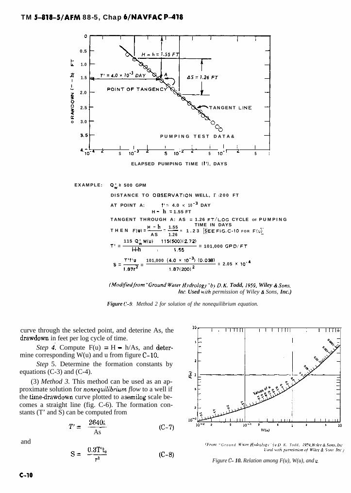
TM 5-818-5/AFM 88-5, Chap WNAVFAC P-418
0.5
k 1.0
isI 1.5
I; 2.0
z0 2.5 TANGENT LINE
2o 3.0
uOP U M P I N G T E S T D A T A &
4.01 ’ I I I I I I . I I I I10-4 2 S lo-3 2 5 lo-2 2 5 lo-’ 2 5 1
ELAPSED PUMPING TIME It’), DAYS
EXAMPLE: QA = 500 GPM
DISTANCE TO OESERVATION WELL, r l 200 FT
AT POINT A: t’ = 4.0 x 10 -’ DAYH - h = 1.55 FT
TANGENT THROUGH A: AS = 1.26 FT/LOG CYCLE OF P U M P I N GH-h 1.55 TIME IN DAYS
T H E N F(U) = -= -=AS 1.26
1 . 2 3 FEE FIG.C-10 FOR ~(“1
115 cl; W(U) 115(~0)~2.72)T’ z
i-i-h l
= 101,000 GPD/FT1.55
T’t’uSz-=
101,000 (4.0 x 10⁻⁹ (0.038)=
1 .S7r2 lB7(200)22.05 x lO-4
-
CMod@dfrom “Ground Waler Hydrology”by D. K. Todd, 19S9, Wiley & Sons#Inc. Used with permission of Wiley & Sons, Inc.)
Figure C-9, Method 2 for solution of the nonequilibrium equation.
curve through the selected point, and deterine As, the IO -I I IllIll I I I lllll I I I IllI+
drawdown in feet per log cycle of time.Step k Compute F(u) = H - h/As, and deter- ’ -
mine corresponding W(u) and u from figure C-lo.Step 5. Determine the formation constants by ’
equations (C-3) and (C-4).
(3) Method 3. This method can be used as an ap-proximate solution for nonequiZibrium flow to a well ifthe time-drawdown curve plotted to a semilog scale be-comes a straight line (fig. C-6). The formation con-stants (T’ and S) can be computed from
2640~7”~ ~ G-V
Asand
0.3T’t0sz ~
rz (C-B)
(From “ G r o u n d Waler H~droh~.s” bv U. K. Todd, 1959, W&s & SO,,Y, I,,?. ._Used wsr/i pwmimon c~f Wder & Sons, Inc.)
Figure C- 10. Relation among F(u), W(u), and u,
C-l0

whereAs = drawdown in feet per cycle of (log) time-
drawdown curveto = time at zero drawdown in days
An example of the use of this method of analysis in de-termining values of T, S, and k is given in figure C-6,using the nonequilibrium portion of the time-draw-down curve.
(4) Gravity flow. Although the equations for non-equilibrium pumping tests are derived for artesianflow, they may be applied to gravity flow if the draw-down is small with respect to the saturated thicknessof the aquifer and is equal to the specific yield of thedewatered portion of the aquifer plus the yield causedby compression of the saturated portion of the aquiferas a result of lowering the groundwater. The procedurefor computing T’ and S for nonequilibrium gravityflow conditions is outlined below.
Step 1. Compute T’ from equation (C-3).
TM 5-818-5/AFM 88-5, Chap WNAVFAC P-418
Step 2. Compute E from equation (C-4) for vari-ous elapsed pumping times during the test period, andplot E versus (log) t’.
Step 3. Extrapolate the S versus (log) t’ curve toan ultimate value for S’.
Step 4. Compute u from equation (C-4) usingthe extrapolated S’, the originally computed T’, andthe original value of r%‘.
Step 5. Recompute T’ from equation (C-3) usinga W(u) corresponding to the computed value of u.
(5) Rechurge. Time-drawdown curves of a testwell are significantly affected by recharge or depletionof the aquifer, as shown in figure C-11. Where re-charge does not occur, and all water is pumped fromstorage, the H’ versus (log) t curve would resemblecurve a. Where the zone of influence intercepts asource of seepage, the H’ versus (log) t curve would re-semble curve b. There may be geological and rechargeconditions where there is some recharge but not
ELAPSED PUMPING T IME (t) -
C U R VE a - ALL WATER FROM STORAGE-NO AQUIFER RECHARGE.
b - CONE OF INFLUENCE INTERCEPTS A SOURCE OF SEEPAGE AT TIME 7.
C - CONE OF INFLUENCE INTERCEPTS A SOURCE OF SEEPAGE AT TIME 1WITH SUPPLY LESS THAN RATE OF PUMPING AT TIME 1.
d - CONE OF INFLUENCE INTERCEPTS AN IMPERMEABLE BOUNDARY AT TIME 7.
U.S. Army Corps of Engineers
Figure C-l 1. lime-dmwdawn curves for various conditions of recharge
C-l 1
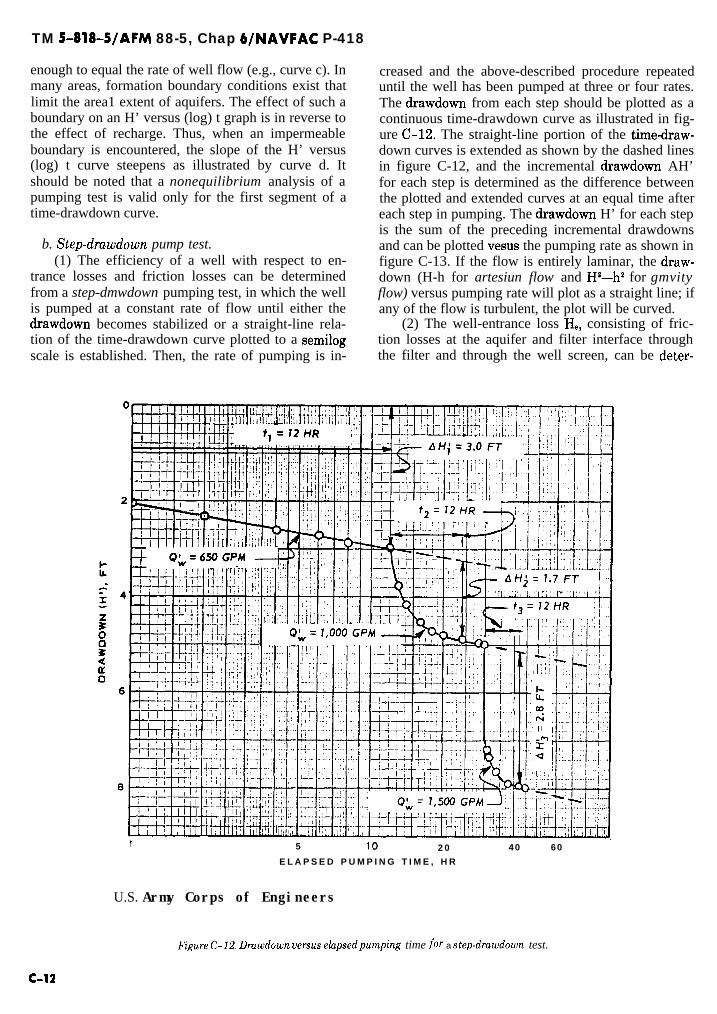
TM 5-818-S/AFM 88-5, Chap 6/NAVFAC P-418
enough to equal the rate of well flow (e.g., curve c). Inmany areas, formation boundary conditions exist thatlimit the area1 extent of aquifers. The effect of such aboundary on an H’ versus (log) t graph is in reverse tothe effect of recharge. Thus, when an impermeableboundary is encountered, the slope of the H’ versus(log) t curve steepens as illustrated by curve d. Itshould be noted that a nonequilibrium analysis of apumping test is valid only for the first segment of atime-drawdown curve.
b. Step-drawdown pump test.(1) The efficiency of a well with respect to en-
trance losses and friction losses can be determinedfrom a step-dmwdown pumping test, in which the wellis pumped at a constant rate of flow until either thedrawdown becomes stabilized or a straight-line rela-tion of the time-drawdown curve plotted to a semilogscale is established. Then, the rate of pumping is in-
creased and the above-described procedure repeateduntil the well has been pumped at three or four rates.The drawdown from each step should be plotted as acontinuous time-drawdown curve as illustrated in fig-ure C-E. The straight-line portion of the time-draw-down curves is extended as shown by the dashed linesin figure C-12, and the incremental drawdown AH’for each step is determined as the difference betweenthe plotted and extended curves at an equal time aftereach step in pumping. The drawdown H’ for each stepis the sum of the preceding incremental drawdownsand can be plotted vesus the pumping rate as shown infigure C-13. If the flow is entirely laminar, the draw-down (H-h for artesiun flow and Ha-h2 for gmvityflow) versus pumping rate will plot as a straight line; ifany of the flow is turbulent, the plot will be curved.
- -
(2) The well-entrance loss He, consisting of fric-tion losses at the aquifer and filter interface throughthe filter and through the well screen, can be deter-
1 5 10 2 0 40 60
E L A P S E D P U M P I N G T I M E , H R
U.S. Army Corps of Engineers
-
figure C-12. Drawdown versus e!-apsedpumping time for a step-drawdown test.
C-l2

TM S-818-5/AFM 88-5, Chap 6/NAVFAC P-418
500 1,000 1,500 2,000
W E L L D I S C H A R G E (Q;), GPM
U.S. Army Corps of Engineers
Figure C-13. Dmwdown versus pumping mte for a step-drawdown test.
mined from the drawdown versus distance plots for a c, Recovery test.step-drawdown pump test as illustrated in figure (1) A recovery test may be made at the conclusion(2-14. The difference in drawdown between the ex- of a pumping test to provide a check of the pumpingtended drawdown-distance curve and the water eleva- test results and to verify recharge and aquifer boun-tion measured in the well represents the well-entrance dary conditions assumed in the analysis of the pump-loss and can be plotted versus the pumping rate as ing test data. A recovery test is valid only if the pump-shown in figure C-15. Curvature of the HW versus Qw ing test has been conducted at a constant rate of dis-line indicates that some of the entrance head loss is the charge. A recovery test made after a step-drawdownresult of turbulent flow into or in the well. test cannot be analyzed.
S. Army Corps of Engineers
Ii:z
EDGE OF WELL F ILTER
1 10 100DISTANCE F R O M W E L L (0, rT
Figure C-14. Dmwdown versus distance for a step-dmwdown test for determining well-entrance loss.
C-l3

TM 5-818-5/AFM 88-5, ChaP 6/NAVFAC P-418
0 5 0 0 1 , 0 0 0 1 , 5 0 0 2 , 0 0 0
W E L L D I S C H A R G E , G P M
U. S. Army Corps of Engineers
Figure C-15. Well-entrance loss versus pumping rate for a step-drawdown test.
(2) When the pump is turned off, the recovery of ratio of log t’k”, where t’ is the total elapsed timethe groundwater levels is observed in the same manner since the start of pumping, and tn is the elapsed timeas when the pump was turned on, as shown in figure since the pump was stopped (fig. C-17). This plotC-16. The residual drawdown H’ is plotted versus the should be a straight line and should intersect the zero
0
QL = SO0 GPM
JUNE 1 JUNE 2 JUNE 3
0 24 46 72 96
TIME, HR
(Courtesy of UOP Johnson Division)
Figure C-16. Typical drawdown and recovery curves fora wellpumpkd and then allowed to rebound.
PUMPING STARTED
J
I N I T I A L S T A T I C
W A T E R L E V E L ,
I--ee ~~~--~~----~
DRAWDOWN
DRAWDOWN
16 F T
C-l4

TM 5-818-5/AFM 88-5, Chap WNAVF;AC P-418
’ = IO 400 GPD/FT
RATIO, t’/t”
(Courtesy of UOP Johnson Division)
Figure C-l 7. Residual dmwdown versus t’/t’ (time during recovery period increased toward the left).
residual drawdown at a ratio of t’k” = 1 if there isnormal recovery, as well as no recharge and no discon-
T , _ 264OkAs’
(C-g)
tinuities in the aquifer within the zone of drawdown. where As’ = residual drawdown in feet per cycle of- The ratio t’/t” approaches one as the length of the re-
covery period is extended.(3) The transmissibility of the aquifer can be cal-
culated from the equation
(log) t’/t” versus residual drawdown curve. Displace-ment of the residual drawdown versus (log) ratio V/t Ucurve, as shown in figure C-B, indicates a variancewith the assumed conditions.
I i I ILARGEINTERCEPT ATZERODRAWDOWN
I
5RECOVERY DU
6
7
6
1 2 3 5 10 20 60 100RATIO, t’/t”
(Courtesy of UOP Johnson Division)
Figure C-18. Displacement of residual dmwdown curve when aquifer conditions vary from theoretical conditions
C-l5

TM 5-818-5/AFM 88-5, Chap 6/NAVFAC P-418
APPENDIX D
EXAMPLES OF DESIGN OF DEWATERING ANDPRESSURE RELIEF SYSTEMS
This appendix consists of figures D-l through D- 10, which follow.
D-l


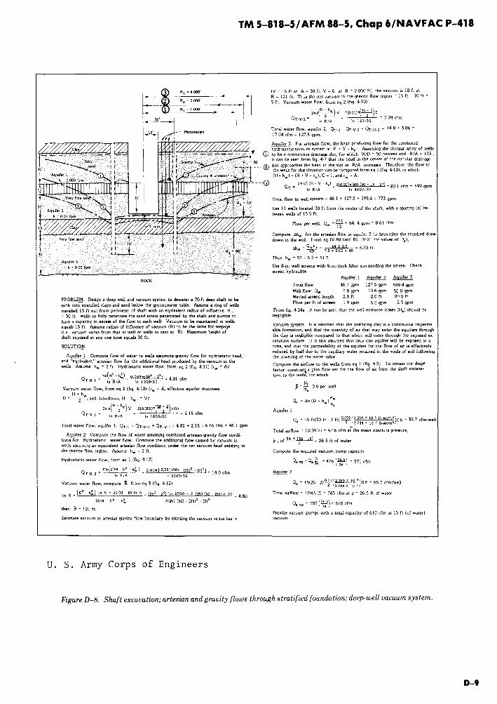


TM 5-818-5/AFM 88-5, Chap 6/NAVFAC P-418
APPENDIX E
TRANSFORMATION OF ANISOTROPIC SOIL CONDITIONSTO ISOTROPIC SOIL CONDITIONS
E-l. General. All of the analytical methods forcomputing seepage through a permeable deposit arebased on the assumption that the permeability of thedeposit is isotropic. However, natural soil deposits arestratified to some degree, and the average permeabil-ity parallel to the planes of stratification is greaterthan the permeability perpendicular to these planes.Thus, the soil deposit actually possesses anisotropicpermeability, with the permeability in the horizontaldirection usually the greatest. To construct a flow netor make a mathematical analysis of the seepagethrough an anisotropic deposit, the dimensions of thedeposit and the problem must be transformed so thatthe permeability is isotropic. Each permeable stratumof the deposit must be separately transformed into iso-tropic conditions. If the seepage flows through morethan one stratum (isotropically transformed), theanalysis can be made by a flow net constructed to ac-count for permeability of the various strata.
E-2. Anisotropic stratum. A homogeneous,anisotropic stratum can be transformed into an iso-tropic stratum in accordance with the following equa-tion: 1
wherey= transformed vertical dimensiony = actual vertical dimension
k,, = permeability in the horizontal directionkV = permeability in the vertical direction
The horizontal dimensions of the problem would re-main unchanged in this transformation. The permea-bility of the transformed stratum, to be used in allequations for flow or drawdown, is as follows:
k=/lGiG (E-2)where k equals the transformed coefficient of permea-bility.
E-3. Effective well penetration. In a strati-fied aquifer, the effective well penetration usually dif-fers from that computed from the ratio of the lengthof well screen to total thickness of aquifer. To deter-
mine the required length of well screen W to achievean effective penetration m in a stratified aquifer, thefollowing procedure can be used. This method is usedin analyses to determine penetration depths needed toobtain required discharge from partially penetratingwells or wellpoints. Each stratum of the previous foun-dation or aquifer with thickness d and horizontal andvertical permeability coefficients kh and kV, respective-ly, is first transformed using equation (E-l) into anisotropic layer of thickness d, where
The transformed coefficientKif permeability of eachstratum from equation (E-2) is
k=V&KVThe thickness of the equivalent homogeneous isotropicaquifer is
m=nl5= Z L (E-3)
m=lwhere n equals the number of strata in the aquifer.The effective permeability of the transformed aquiferis
m - nI
km = l ham‘2= I5 (E-4)
where n equals the number of strata in the aquifer.The effective well-screen penetration into the trans-formed aquifer is
m=j-1I
w= wikhl + m = 1 dmkhm
l-L(E-Q
wherewf = actual well penetration in strata 1
1 = number of strata penetrated by wellThe penetration of the well screen in the transformedaquifer (expressed as a decimal) is m/D, where w andD are obtained from equations (E-5) and (E-3), respec-tively.
E - l

TM 5-818-5/AFM 88-5, Chap WNAVFAC P418
APPENDIX F
WELL AND TOTAL DISCHARGE MEASUREMENTS
F-l. General. The simplest method for determin-ing the flow from a pump is to measure the volume ofthe discharge during a known period of time by collect-ing the water in a container of known size. However,this method is practical only for pumps of small capac-ity; other techniques must be used to measure largerflows.
F-2. Pipe-flow measurements.a. Venturi meter. The flow from a dewatering sys-
tem can be accurately measured by means of a venturimeter installed in the discharge line. In order to obtainaccurate measurements, the meter should be locatedabout 10 pipe diameters from any elbow or fitting, andthe pipe must be flowing full of water. The flowthrough a venturi meter can be computed from
where
3.12 =
c=Z
A =
Q z 3.12&4 z “kdh - “’ii=-F
F-U
conversionf a c t o r =
7.48 gal/fV x 60 sec/min
144 in.21ft2flow, gallons per minutecalibrated coefficient of discharge (usuallyabout 0.98)area of entrance section where upstreammanometer connection is made, squareinches
g Z
hI-hZ =
acceleration of gravity (32.2 feet per secondsquared)difference in pressure between entrancesection and throat, as indicated bymanometer, feet
R= ratio of entrance to throat diameter = d/d,The pressures hI and h2 may be taken as illustrated infigure F-l for low pressures, or by a differential mer-cury manometer for high pressures. Gages may beused but will be less accurate.
b. Orifices.(1) The flow from a pipe under pressure can be
conveniently measured by installation of an orifice onthe end of the pipe (fig. F-2) or by insertion of an ori-fice plate between two flanges in the pipe (fig. F-3).The pressure tap back of the orifice should be drilled atright angles to the inside of the pipe and should be per-fectly smooth as illustrated in figure F-4. A rubbertube and glass or plastic pipe may be used to measurethe pressure head. The diameter of the orifice plateshould be accurate to 0.01 inch; the edge of the plateshould be square and sharp, should have a thickness ofy8 inch, and should be chamfered at 45 degrees asshown in figure F-2. The approach pipe must besmooth, straight, and horizontal; it must flow full, andthe orifice should be located at least eight pipe diam-eters from any valves or fittings. The flow for varioussized cap orifice-pipe combinations can be obtainedfrom figure F-5.
(2) The flow through an orifice in a pipe can becomputed from
whereQ= capacity, cubic feet per secondC = orifice discharge coefficient
AZ = area of orifice, square feetdZ = orifice diameter, inchesd, = pipe diameter, inchesg = 32.2 feet per second squaredh = pressure drop across the orifice in feet of head(3) The expression dl - (dJd,) corrects for the
velocity of approach. The reciprocal of this expressionand the coefficient C are listed in the following tabula-tion for various values of d21dI.
Figure F-l. Venturi meter. Figure F-2. Pipe cup orijice,
F-l

TM S-818-5/AFM 88-5, Chap WNAVFAC P-418
2.6h,,,
Figure F-3. Orifice in pipe.
Figure F-4. Approvedpressure taps.
dJd, C1
dl - (dJdJ
0.25 0.604 1,0020.30 0.605 1.0040.35 0.606 1.0060.40 0.606 1.0130.50 0.607 1.0330.60 0.608 1.0720.70 0.611 1.1460.80 0.643 1.3010.90 0.710 1.706
Note: The diameter of the orifice should never be larger than 80percent of the pipe diameter in order to obtain a satisfactory pres-sure reading.
c. Pitot tube. The flow in a pipe flowing full can alsobe determined by measuring the velocity at differentlocations in the pipe with a pitot tube and differentialmanometer, and computing the flow. The velocity atany given point can be computed from
v=cB& (F-3)where
v = velocityC = meter coefficientg = acceleration of gravity
h.., = velocity headThe flow is equal to the area of the pipe A times theaverage velocity V, or
Q = A V (F-3a)
. ”
D I S C H A R G E , ‘P,,,
(courtesy of Fairbanks Morse, Inc., Pump Division)
Figure F-5. Pipe cap orifice chart.
F - 2

TM 5-818-5/AFM 88-5, Chap WNAVFAC P-418
where
!L
andv = velocity at center of concentric rings of equal
arean = number of concentric rings
F-L Approximate measurement meth-ods.
a. Jet flow. Flow from a pipe can be determined ap-proximately by measuring a point on the arc of thestream of water emerging from the pipe (fig. F-6),using the following equation:
where
Q=A =
x =
Y=
3.6lAxQ= fi (F-4)
flow, gallons per minutearea of stream of watersquare inches. If the pipe
at end of pipe inis not flowing full,
the value of A is the cross-sectional area of thewater jet where it emerges from the pipe. Thearea of the stream can be obtained by multi-plying the area of the pipe times the EffectiveArea Factor (EAF) in figure F-7 using theratio of the freeboard to the inside diameter ofthe pipe.distance along axis of the discharge pipethrough which the stream of water movesfrom the end of the pipe to a point(s), inchesdistance perpendicular to the axis of the dis-charge pipe through which the stream ofwater drops, measured from the top or surfaceof the stream of water to point(s), inches
It should be noted that the x and y distances are meas-ured from the top of the stream of water; if y is meas-ured in the field from the top of the pipe, the pipe
PIPE AXIS
thickness and freeboard must be s&ructed from themeasured y to obtain the correct value of y.
b. Fountain flow. The flow from a vertical pipe canbe approximated by measuring the height of the use ofthe stream of water above the top of the pipe (fig.F-8). Two types of flow must be recognized when deal-ing with fountain flow. At low crest heights, the dis-charge has the character of weir flow, while at highcrest heights the discharge has the character of jetflow. Intermediate values result in erratic flow withrespect to the height of the crest H.
(1) Where the flow exhibits jet character, it can becomputed from
whereQ=K =
D=H=
Where
Q = 5.68KD’a (F-5)
flow, gallons, per minuteconstant varying from 0.87 to 0.97 for pipes 2to 6 inches in diameter and h = 6 to 24 inchesinside pipe diameter, inchesvertical height of water jet, inchesthe flow exhibits weir character, it can be ap-
proximated by using the Francis Formula, Q = 3.33Bh3’2, with B being the circumference of the pipe.
(2) Some values of fountain flow for various nom-inal pipe sizes and heights of crest are given in tableF- l .
F-4. Open channel flows.a. Weirs. Flow in open channels can be measured by
weirs constructed in the channel. Certain dimensionalrelations should be recognized in constructing a weirto obtain the most accurate flow measurements asshown in figure F-9. The weir plate should be a non-corrosive metal about % inch thick with the crest Y8inch wide, and the downstream portion of the platebeveled at 45 degrees, The crest should be smooth, andthe plate should be mounted in a vertical plane perpen-dicular to the flow. The channel walls should be
V. S. Army Corps ot Engineers
Figure F-C Flow from pipe.
F-3

TM 5-818-5/AFM 88-5, Chap 6/NAVFAC P-418
a
0.6
0.2
0.1 -
0
0 0.1 0.2 0.3 0.4 0.5 0.6 0.7 0.8 0.9 1 .cJ
FREE8OARD tF)/lNSlDE PIPE DIAMETER, D
LJ. S. Army Corps of Engineers
Figure F-7. Effective area factor for partially filledpipe,
Table F-l. Flow (gallons per minute) from Vertical Pipes
Height of Crest H Nominal Diameter of Pipe, inchesinches 2 3 4 5 6 8
l-l/Z 22 43 68 85 110 160
2 26 55 93 120 160 230
3 33 74 130 185 250 385
4 38 88 155 230 320 520
5 44 99 175 270 380 630
6 48 110 190 300 430 730
8 56 125 225 360 510 900
10 62 140 255 400 580 1050
12 69 160 280 440 640 1150
15 78 175 315 500 700 1300
18 85 195 350 540 780 1400
21 93 210 380 595 850 1550
24 100 230 400 640 920 1650
-
‘J. S. Army Corps of Engineers
F-4
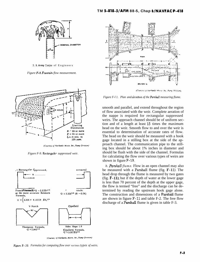
3. S. A r m y Corps of Engineers
Figure F-8. Fauntuin flow measurement.
L = 4h min. to1Oh max.
Figure F-9. Rectnngulur suppressed weir.
, Rectangula; S u p p r e s s e d ,r;, 3
Francis Formula, Q = 3.33BlP’*or the mcne accurate RchbockFormula,
r
Q = 3.33W* (B - O.Zh)
smooth and parallel, and extend throughout the regionof flow associated with the weir. Complete aeration ofthe nappe is required for rectangular suppressedweirs. The approach channel should be of uniform sec-tion and of a length at least 15 times the maximumhead on the weir. Smooth flow to and over the weir isessential to determination of accurate rates of flow.The head on the weir should be measured with a hookgage located in a stilling box at the side of the ap-proach channel. The communication pipe to the still-ing box should be about 1% inches in diameter andshould be flush with the side of the channel. Formulasfor calculating the flow over various types of weirs areshown in figure F-lo.
b. Parshd flume. Flow in an open channel may alsobe measured with a Parshall flume (fig. F-11). Thehead drop through the flume is measured by two gates(fig. F-11); but if the depth of water at the lower gageis less than 70 percent of the depth at the upper gage,the flow is termed “free” and the discharge can be de-termined by reading the upstream hook gage alone.The construction and dimensions of a Parshall flume
Q = (3.228 + 0 . 4 3 5 9 Bhel’* are shown in figure F-l1 and table F-2. The free flowdischarge of a Parshall flume is given in table F-3.
V-Notch CitAletti
I I 1 1
Thompson Formula, Sides Slope 1:4Q = 2.S4hs” Cipolletti Formula,
Q = 3,3blBh’jL
TM 5-818-5/AFM 88-5, Chap 6/NAVFAC P-418
~____.___.._~..__ . . . . T_..f._.d ._--... c _.... -, .,
Figure F-l 1. Plan and elevativn of the Parshnll measuring flume.
Figure F- IO, Formulas for computing flow over various types of weirs.
F-S


TM 5-818-5/AFM 88-5, Chap WNAVFAC ~418
APPENDIX G
EXAMPLES OF DETAILED DEWATERING SPECIFICATIONS
G-l. General. This appendix provides examplesbased on actual specifications for installation of de-watering or pressure relief systems, extracted fromGovernment and private industry contract documents.They have been selected and presented to illustrate thevarious types of specifications described in the test(para 7-2).
G-2. Types of specifications.a. Type A specifications are projects where the de-
watering is not too critical with respect to damage tothe permanent work or safety to personnel, and onlythe desired results are to be specified. This type ofspecifications makes the Contractor completely re-sponsible for design, installation, and operation of thesystem(s). Specifications may be brief (type A-l) ormore detailed (type A-2), depending upon complexityand criticality of the dewatering or pressure relief sys-tem. The examples of these two types are from Corpsof Engineers projects.
b. Type B specifications are recommended for large,complex systems, or where the dewatering or pressurerelief is critical with regard to construction of the proj-ect, damage to permanent work, and safety.
(1) Type B- 1. A specification that gives a detaileddesign and requirements for installation of a “mini-mum” system but makes the Contractor responsiblefor operating and maintaining the system, supple-menting it as necessary to obtain the required results.The installation is then checked with a full-scalepumping test to verify its adequacy.
(2) Type B-2. A specification that gives a detaileddesign and installation procedure but makes the Con-tractor responsible only for normal repairs and opera-tions. The Government or Owner thus assumes the re-sponsibility for the adequacy of the system and itscomponents, major repairs, and replacement of equip-ment if necessary.
(3) Type B-3. A specification that is similar totype A, wherein only the desired results are specified,except the degree of difficulty or criticality of the sys-tem requires that the Contractor retain an “Expert” inthe field of dewatering or pressure relief systems to de-sign, supervise installation, and monitor the system.
c. Types A-l and B-3 specifications should not beused unless the issuing agency has considerable confi-dence in the (dewatering) qualification of the bidders;
ample time and knowledge to check the Contractor’ssubmittals; and a willingness to reject the Contractor’sproposals and accept any associated delays in startingthe project until an acceptable design is submitted.
d. For large and complex dewatering projects wheredewatering is critical to the safety of the work, typeB-l specifications are recommended; types A-2 andB-3 may be suitable if the Owner or Engineer can orwill enforce the provisions relating to approval of de-sign, installation, and operation.
G-L Example of type A-l specifications(dewatering).
u. Gene&. The Contractor shall provide all de-watering necessary to keep the construction and workareas dry. The Contractor shall design, install, oper-ate, and maintain an adequate system. The systemshall be of sufficient size and capacity to maintain adry condition without delays to construction opera-tions.
b. Submittals. The Contractor shall submit a pro-posed dewa terihg ph for approval of the ContractingOfficer prior to initiation of any construction or exca-vation operations, The plan shall show all facilitiesproposed for complying with this section.
c. Puyments. Payment for all work covered in thisspecification will be made at the contract lump sumprice for “dewatering,” which price shall constitutefull compensation for furnishing all plant, equipment,labor, and materials to install, operate, maintain, andremove the dewatering system.
G-4. Example of type A-2 specifications(dewatering).
u. Scope. This section covers the design, furnishing,installation, operation, maintenance, and removal of adewatering system, complete.
b. Dewatering.(1) Gene&. The dewatering system shall be of a
sufficient size and capacity as required to controlhydrostatic pressure on all clay strata below elevation- 13.0 feet to depths indicated by the logs of borings,to permit dewatering of the area specified in para-graph d below, and to allow all material to be exca-vated, piles driven, and concrete placed, all in a drycondition. The system shall include a deep-well sys-tem, a wellpoint system, other equipment, appurte-

TM 5-818-5/AFM 88-5, Chap 6/NAVFAC P-418
nances, and related earthwork necessary for the re-quired control of water. The sequence of installation ofcomponents of the dewatering system shall be in ac-cordance with the specifications and drawings. Thesystem shall remain in continuous operation, as speci-fied, until a written directive to cease dewatering oper-ations has been received from the Contracting Officer.
(2) Co&roZ of wuter. The Contractor shall control,by acceptable means, all water regardless of source.Water shall be controlled and its disposal provided forat each berm. The entire periphery of the excavationarea shall be ditched and diked to prevent water fromentering the excavation. The Contractor shall be fullyresponsible for disposal of the water and shall provideall necessary means at no additional cost to the Gov-ernment.
c. Design. The dewatering system shall be designedusing accepted and professional methods of design andengineering consistent with the best modern practice.The dewatering system shall include the deep wells,wellpoints, and other equipment, appurtenances, andrelated earthwork necessary to perform the function.A representative of the Contractor shall visit the siteto determine the conditions thereof. The Contractorshall be responsible for the accuracy of the drawingsand design data required hereinafter.
(1) Drawings and design data. The Contractorshall submit for the approval of the Contracting Of-ficer, within 30 calendar days after receipt of Notice toProceed, drawings and complete design data showingmethods and equipment he or she proposes to utilize indewatering, including relief of hydrostatic head, andin maintaining the excavation in a dewatered and in ahydrostatically relieved condition. The material to besubmitted shall include, but not necessarily be limitedto, the following:
(u) Drawings indicating the location and size ofberms, dikes, ditches, all deep wells, observation wells,wellpoints, sumps, and discharge lines, including theirrelation to water disposal ditches.
(b) Capacities of pumps, prime movers, andstandby equipment.
(b) Design calculations proving adequacy of sys-tem and selected equipment.
(d) Detailed description of dewatering proce-dure and maintenance method.
(2) Responsibility. Approval by the ContractingOfficer of the plans and data submitted by the Con-tractor shall not in any way be considered to relievethe Contractor from full responsibility for errorstherein or from the entire responsibility for completeand adequate design and performance of the system incontrolling the water level in the excavated area andfor control of the hydrostatic pressures to the depthshereinbefore specified. The Contractor shall be solelyresponsible for proper design, installation, proper
operation, maintenance, and any failure of any compo-nent of the system.
d. Dewa tering sys tern,(1) Deep-well system. The clay and sand strata be-
low elevation -13.0 feet are continuous over a largearea. Removal of soils above elevation -25.0 feet. Adeep-well system shall be provided to relieve this pres-sure. The pressure shall be relieved in the sand stratasuch as those indicated on boring S-II-SS-l-62(A)from 67.5 to 72.0 feet and from 85.5 to 142.5 feet.These strata will vary in elevation and thickness overthe area. The deep-well system shall be of sufficientcapacity to lower the hydrostatic head to elevation-40.0 feet as measured in observation wells at ninepoints in the excavation. One installed spare deep well,complete and ready for immediate operation, shall beprovided for each two operating wells. The use of gaso-line prime movers will not be permitted in the opera-tion of deep wells. At each of the nine points two ob-servation wells shall be installed. One observation wellshall be installed with the screen in the upper sands,and one observation well shall be installed with thescreen in the lower sands. The riser pipe for the obser-vation wells will be 2-inch pipe in 5-foot sections. Oneof the observation points shall be constructed at co-ordinate N254 460, E260 065. The remainder of theobservation points will be located by the ContractingOfficer after the dewatering plan is submitted. The ex-act tip elevation of all observation wells will be estab-lished after the dewatering plan is submitted; how-ever, the tip elevation in the lower sand will be at least100 feet below original ground surface, and the tip ele-vation of the observation wells in the upper sands willbe approximately 70 feet below original ground sur-face. The Contractor shall maintain the observationwells and keep daily records of readings until other-wise directed by the Contracting Officer.
(2) Wellpoint system. A wellpoint system shall beused above the top of clay shown on the borings at ap-proximate elevation -14.0 feet but to dewater thearea from original ground surface to the top of theclay. This system shall have sufficient capacity to low-er the head within the excavation to the top of theclay.
e. Available soil test data and pumping test data.The soil test data obtained by the Government areshown on the boring logs. Additional laboratory dataand samples of the soils from borings shown in theplans are available in the District office for inspectionby bidders. Typical permeability data from laboratorytests at this site are tabulated. Pumping tests have notbeen made at the site; however, the soil profile at theB-l and B-2 test stand excavation is similar to thissite and this excavation is now being dewatered by adeep-well system. Data on this system can be inspected
_
G-2

TM 5-818-5/AFM 88-5, Chap 6/NAVFAC P-418
at the office of the Area Engineer or in the District of-fice.
f. S&n&y equipment. The Contractor shall furnishstandby pumping equipment power as follows:
(1) Diesel, liquid petroleum gas, and gasolinefueled prime movers for pumps shall have 50 percentstandby equipment.
(2) Portable electric generators shall have 100percent standby generating equipment.
(3) Commercial electric power, which is availableat the site, shall have 100 percent standby electric gen-erating equipment.
(4) The Contractor shall provide not less than onecomplete spare pumping unit for every five pumpingunits other than deep-well pumps in the system. In nocase shall less than one standby pumping unit be pro-vided. The sizes of the standby pumping units shall besubject to the approval of the Contracting Officer.
g. Dumuges. The Contractor shall be responsiblefor, and shall repair without cost to the Government,any damage to work in place, the other Contractors’equipment, and the excavation, including damage tothe bottom due to heave and including removal of ma-terial and pumping out of the excavated area that mayresult from his or her negligence, inadequate or im-proper design and operation of the dewatering system,and any mechanical or electrical failure of the de-watering system.
h. Maintaining excavation in dewatered condition.(1) Gene&. Subsequent to completion and accept-
ance of all work, including piling and concrete work, inthe excavated area, the Contractor shall maintain theexcavation in a dewatered condition and the waterlevel in the observation wells at the specified and ap-proved elevation until such time as the succeedingContractor commences dewatering operations, and awritten directive to cease pumping operations hasbeen received from the Contracting Officer. Systemmaintenance shall include but not be limited to 24-hour supervision by personnel skilled in the operation,maintenance, and replacement of system components;standby and spare equipment of the same capacity andquantity as specified in f above; and any other work re-quired by the Contracting Officer to maintain the ex-cavation in a dewatered condition. Dewatering shall bea continuous operation and interruptions due to out-ages, or any other reason, shall not & permitted.
(2) Responsibility. The Contractor shall be respon-sible for all damages to accepted work in the excava-tion area and for damages to any other area caused byhis or her failure to maintain and operate the systemas specified above or from water overflowing his or herditch.
i. System removal. Upon receipt of written directiveto cease dewatering operations from the Contracting
Officer, the Contractor shall remove all dewateringequipment from the site, including related temporaryelectrical secondary as approved by the ContractingOfficer. All wells shall be plugged and/or filled, Re-moval work required under this paragraph does not in-clude any of site cleanup work as required elsewhere inthese specifications.
j. Method of measurement. Dewatering, as specifiedin Q2) below, to be paid for will be determined by thenumber of calendar days (24 hours), counted on a day-to-day basis, the excavation is maintained in a de-watered condition, measured to the nearest hour, fromcompletion and final acceptance of the concrete foun-dation for the A- 1 test stand area to the date on whicha written directive to cease pumping operations is re-ceived from the Contracting Officer.
k. Payment.(1) Dewatering during excavation and construc-
tion. Payment for furnishing all designs and engineer-ing data, plant, labor, equipment, material, and appur-tenances and for performing all operations in connec-tion with designing, furnishing, installing, operating,and maintaining the dewatering system until the workin the area is completed and accepted will be made atthe applicable contract lump sum price for “Dewater-ing A-l Test Stand Area, Deep Wells,” and “Dewater-ing A-l Test Stand Area, Except for Deep Wells.”Twenty-five percent of the contract price for each itemwill be paid upon completion of the installation of thedewatering system for the excavation. A second 25percent of the contract price for each item will be paidupon satisfactory completion of 80 percent of the esti-mated excavation quantity. A third 25 percent of thecontract price for each item will be paid upon satisfac-tory completion of 100 percent of the required excava-tion. Fifteen percent of the contract price for eachitem will be paid when final acceptance of all work inthe excavation is made. The remaining 10 percent ofthe contract price for each item will be paid after writ-ten notice to cease dewatering operations has been is-sued and final cleanup and final acceptance of all workhas been made.
(2) Maintaining area in dewatered condition. Pay-ment for furnishing all plant, labor, equipment, andmaterial and for performing all operations in connec-tion with maintaining the accepted excavations in adewatered condition will be made at the applicablecontract unit price per calendar day for “MaintainingA-l Test Stand Excavation in Dewatered Condition.”No payment will be made for this item for periods,measured to nearest hour, during which the dewater-ing system is not operated and maintained as specifiedhereinbefore.
(3) Removal of systems. Payment for furnishingall plant, labor, equipment, and material and for per-forming all operations in connection with removal of
G-3
TM 5-818-5/AFM 88-5, Chap WNAVFAC P-418
the dewatering system will be made at the applicablecontract lump sum price for “Removal of A-l TestStand Dewatering System.” However, if the Contrac-tor so elects to sell the installed and operating systemto the succeeding Contractor or to dispose of the sys-tem in place by other means, as approved by the Con-tracting Officer, the Contractor shall be relieved fromthe requirements of the specified removal work and nopayment will be made for this item.
G-5. Example of type B-l specifications(dewatering and pressure relief).
u. Scope. This section covers furnishing, installa-tion, operation, maintenance, and removal of the jet-eductor wellpoint and pressure relief well systems, assubsequently specified in this section; control of anyseepage from the soils above the bottom of the excava-tion not intercepted by the jet-eductor wellpoint sys-tem deemed necessary by the Contractor to permit in-stallation of the sheeting shown to grade as specified;pumping of surface water or seepage through thesheeting during excavation or after the jet-eductor de-watering system is turned off or removed; and install-ing any additional pressure relief wells, pumps, andappurtenances, if necessary, to maintain the hydro-static water level in the clayey silty sand and sandy silt(semipervious) stratum (about el 2352 1 foot) beneaththe excavation at all times.
b. Responsibility. The Contractor shall be fully re-sponsible for furnishing, installing, operating, main-taining, and removing all wellpoint, pressure relief,and seepage or surface ,:vater control systems. How-ever, any pressure relief wells, pumps, piping, andelectrical wiring and controls required to lower andmaintain the hydrostatic water level in the semiper-vious stratum below the bottom of the excavation, oth-er than the pressure relief system specified, will bepaid for as an extra.
(1) The Contractor shall be responsible for:(u) Installing and testing the wellpoint and pres-
sure relief systems as specified.(b) Dewatering or controlling any seepage from
the soils above the bottom of the excavation so thatthe sheeting may be installed without any significantsloughing of earth during excavation and placement ofsheeting and pea gravel backpack.
(c) Maintaining the hydrostatic water level inthe semipervious stratum below elevation 250.0 feetat all times.
(cZ) Maintaining the bottom of the excavationfree of all seepage or surface water until the structuralmat has been placed and the waterproofing installedup to the top of the mat.
(e) Operating, maintaining, and monitoring thewellpoint and pressure relief well systems. Systemmaintenance shall include but not be limited to at least
G-4
daily supervision by someone skilled in the operation,maintenance, and replacement of system components;at least one spare submersible pump and controls andone pressure pump of the same capacity as specified;and any other work required by the Contracting Offi-cer to maintain the excavation in a dewatered andhydrostatically relieved condition. Dewatering andpressure relief shall be a continuous operation and in-terruptions due to power outages, or any other reason,shall not be permitted. Some responsible person shallalso monitor the dewatering sump pumping, andpumping the relief wells continuously until the suc-ceeding contractor assumes the responsibility for such,and the Contractor has received a written instructivethat he or she is no longer responsible for this oper-ation.
--
(2) The Contractor shall also be fully responsiblefor any failure of any component of the systems. TheContractor shall be responsible for all damages towork in the excavation area and for damages to anyother area caused by failure to maintain and operatethe dewatering and pressure relief systems as speci-fied.
c. Wellpoint and pressure relief systems.(1) Gene&. The jet-eductor wellpoint system
specified is to lower the groundwater table adjacent tothe excavation and intercept seepage from the sandyand gravelly soil above the Cockfield formation (atabout el 253.0 feet) so that excavation and placementof the wood sheeting and pea gravel backpack can beaccomplished with minimum difficulty, and with littleif any sloughing of the soil from the cut slope. Thewellpoint system combined with a sump ditch betweenthe sheeting and edge of structural mat when properlyinstalled, maintained, and pumped should permit plac-ing the “mud” mat on foundation soils free of any sur-face water. If the Contractor considers the spacing ofthe wellpoints inadequate to accomplish the excava-tion and placement of the wood sheeting, as specified,he or she should space the wellpoints closer. The well-point system shall remain in continuous operation un-til the excavation has been dug to grade and the “mud”mat poured. After the “mud” mat has been placed, thewellpoint system may be turned off and any seepagethrough the wood sheeting removed by sump pump-ing. After the “A” piezometers for monitoring thegroundwater table above the Cockfield formation andthe wellpoint system have been installed, the systemshall be tested for flow and groundwater lowering pri-or to starting any excavation. The well system is to re-lieve excess hydrostatic pressure in the semiperviousstratum below the excavation to insure no heave of thesoil strata above this stratum. It is imperative that noheave of the soil strata above the semipervious stra-turn occur inasmuch as the building will be founded di-rectly on the foundation soils above this stratum.
_,
-

TM 5-818-5/AFM 88-5, Chap WNAVFAC P-418
(2) Control of wuter. The Contractor shall controlall surface water, any seepage into the excavation, andhydrostatic pressure in the semipervious stratum be-neath the excavation, regardless of source. Any open-ing in the wood lagging, through which seepage is car-rying any soil, shall be promptly caulked. Any waterseeping, falling, or running into the excavation as it isdug shall be promptly pumped out.,The entire periph-ery of the excavation area shall be suitably diked, andthe dike maintained, to prevent any surface waterfrom running into the excavation. The Contractorshall be fully responsible for disposal of all water fromthe excavation and from the wellpoint and relief wellsystems in an approved manner at no additional costto the Government.
(3) Wellpoint and pressure relief system data. TheContractor shall submit for approval by the Contract-ing Officer, within 10 calendar days after receipt ofNotice to Proceed, complete information regardingmotor generator, pumps, wellpoints, jet-eductors, wellscreens, and any other equipment that he or she pro-poses to utilize in dewatering and relieving hydrostaticpressure, and in maintaining the excavation in a dewa-tered and hydrostatically relieved condition. The datato be submitted shall include, but not necessarily belimited to, the following:
(u) Characteristics of pumps and motor gener-ator, and types and pertinent features of well screens,wellpoints, and jet-eductor pumps.
(b) Plans for operating, maintaining, and moni-toring the wellpoint and relief well systems.
(4) Jet-eductor wellpoint system.(u) The soils at the site consist essentially of fill,
clays and silts, and some silty sand and clay sands withoccasionally pea gravel above the Cockfield formation.The jet-eductor wellpoint system has been designed tolower the groundwater table and intercept most of theseepage that will flow toward the excavation. Becauseof the impervious Cockfield formation at about thebottom of the excavation, it is not possible to lower thegroundwater table and intercept most of the seepagethat will flow toward the excavation as it is dug. Be-cause of the impervious Cockfield formation at aboutthe bottom of the excavation, it is not possible to lowerthe groundwater table completely down to the top ofthis stratum or to intercept all seepage above it. Byproper installation, the jet-eductor wellpoint systemshould intercept most of the seepage and stabilize thesoil sufficiently to install the wood sheeting subse-quently specified without any significant sloughing ofthe soil behind the sheeting prior to placement of thepea gravel backpack. The fact that some minor seepagemay bypass the wellpoints should be anticipated bythe Contractor. The tips for the wellpoints shall be in-stalled approximately 12 inches below the top of the
Cockfield formation as encountered during installa-tion of the system.
(b) The wellpoints shall have a minimum screenor slotted length of 30 inches and shall be of the “bot-tom suction” type. The wellpoint screens shall be of 30-mesh cloth or have #25 slots. The wellpoints shall be ofa high-capacity type with a diameter of approximately2% inches. The jet-eductor pumps and pressure and re-turn riser pipes shall have a capacity and be operatedat a pressure which will produce a minimum flow of 2gallons per minute with a static lift of 25 feet. If theContractor uses jet-eductor pumps with a yield capac-ity greater than 3 gallons per minute, it will be neces-sary for him to redesign the pressure and return head-er lines. The pressure pumps and recirculation tankshall be designed by the Contractor. The pumps shallhave adequate head and pumping characteristics tomatch the number and capacity of the jet-eductors be-ing used. Both the pressure and return header linesshall be provided with pressure gages at the pumpsand across the excavation from the pumps. Overflowfrom the recirculation tank shall be arranged so thatthe flow from the wellpoint system can ye readilymeasured.
(c) The filter sand to be placed around the well-points and up to within 10 feet of the ground surfaceshall be a clean, washed sand (A) having a gradationfalling within the following range:
U.S. Standmd filter Sand ASieve Size Percent Passing
10 78-10016 35-8220 15-5830 3-3240 0-1350 0-3
(d) The wellpoints shall be installed by a combi-nation of driving and jetting (with a hole puncher) a12-inch “sanding” casing to approximately 1 foot be-low the top of the Cockfield formation, rinsing the“sanding” casing until there is no more sediment in thecasing, centering the wellpoint and lowering it to thebottom of the hole, placing Filter Sand A in the casingaround the wellpoint in a heavy continuous stream upto within 10 feet of the ground surface, and then fill-ing the remainder of the hole with a thick bentoniticgrout or by pouring in a mixture of dry sand contain-ing 10 percent granular bentonite, up to the groundsurface. Before the working day is over, all wellpointsinstalled that day shall be pumped with a small centri-fugal pump, capable of producing a 25-foot vacuum,until the effluent becomes clear. Jet water used for in-stalling the wellpoints shall be clear polished so thatreturn of jet water up through the sanding casing isachieved before the casing has been driven to a depthof more than about 10 feet from the surface. It may benecessary or expeditious to prebore the holes for the

TM 5-818-5/AFM 88-5, Chap WNAVFAC P-418
wellpoints with a lo-inch auger prior to driving andjetting the 12-inch sanding casing to grade, Any suchpredrilling should be accomplished in a manner whichwill not cause any caving of the hole as it is drilled. Injetting the sanding casing for the wellpoints, provisionshall be made to prevent jet water from spraying oversidewalks and streets being used for pedestriansand/or vehicular traffic, and from running over or intostreets being used by such. The Contractor will be re-sponsible for disposal of jet water in a manner satisfac-tory to the City and the Construction Manager.
(e) Each jet-eductor wellpoint shall be providedwith a suitable strainer at the top of the pressure riserpipe to prevent the entrance of any particles, whichmight clog the jet-eductor nozzle, and a stopcock orvalves, which will permit isolating the wellpoint topermit pressure testing and pumping the wellpointseparately if desired,
(5) Pressure relief wells and pumps. The pressurerelief wells shall be installed at the locations specified,These wells are to redice the hydrostatic head in thesemipervious stratum below the excavation to eleva-tion 250.0 feet or lower as measured by the B piezome-ters installed in this same stratum at the locations, assubsequently specified.
(a) The screens for the relief wells shall be 10feet long and shall be installed in the semiperviousstratum at about elevation 235& 1 foot. The screensshall have a nominal diameter of 4 inches. They maybe manufactured of slotted Schedule 40 PVC pipe,Johnson wire-wrapped screen, or other approvedscreen. The screens shall be covered with 30-meshbrass or stainless steel gauze or slotted with #20 slotswith a minimum open area of 5 percent. The riser pipeshall also have a 4-inch nominal diameter; it may beeither PVC plastic pipe or steel. The screen portion ofthe wells and up for a distance of 5 feet above the topof screen shall be surrounded with a clean, washed uni-form filter sand (B) with the following gradation:
U.S. Standard Filter Sand BSieve Size Percent Passing
10 95-10020 58-9030 30-7340 5-5050 0-2570 0-8
Suppliers who can furnish Filter Sands A &id B are asfollows:
Filter Sand Filter SandSupplier A B
1. - - -
2. - - -3. - - -
(b) Pumps for the relief wells shall be submersi-ble pumps suitable for installation in 4-inch nominaldiameter wells with a capacity of 3 to 10 gallons per
G-6
minute at a total dynamic head (TDH) equal to 50 feet.The Contractor shall be responsible for designing andinstalling the electrical system for powering the sub-mersible pumps in the relief wells. The electrical sys-tem shall meet the local electrical code and be ap-proved by the Contracting Officer. Each pump shall beprovided with a starter and fuse disconnect with aclearly visible red light mounted on the control panelthat shows red when the pump is running. A motorgenerator with a capacity capable of starting all of thesubmersible pumps in the relief wells at one time shallbe provided and hooked into the electrical system at alltimes. This generator shall be operated to keep thepumps in the relief wells running in event of powerfailure. It shall be maintained in first class condition,protected from the weather, and started at least twicea week to check its operating condition.
(c) The bottom of the screens for the relief wellsshall be installed at or slightly below the bottom of thesemipervious stratum as encountered during installa-tion. They shall be installed using the same procedureas specified for the wellpoints except that in all proba-bility it will be necessary to predrill the holes to gradewith a lo-inch auger because of the difficulty in jettingthrough some of the clay strata to be penetrated. Afterthe (12-inch) sanding casing has been driven and jettedto grade, the well screen and riser pipe shall be cen-tered accurately and lowered to within 1 foot of thebottom of the casing. Filter Sand B poured into thesanding casing around the well riser pipe in a heavysteady stream until the filter sand is at least 5 feetabove the top of the screen; the remainder of the holemay be filled with clean medium sand. The sandingcasing shall then be immediately pulled. After the wellhas been installed, it shall be promptly pumped with acentrifugal pump capable of producing a 25-foot va-cuum until the effluent is clear. The submersible pumpthen shall be lowered and suspended in the well withthe intake of the pump at about the top of the wellscreen. The pump or discharge pipe shall be providedwith a check valve, and the connection between thedischarge pipe from the pump to header pipe shall beprovided with a gate valve which will permit removalof the pump if necessary. The top of the well shall besealed with a suitable well cap or plate provided with ahole through which a sounding line may be lowered todetermine the water level in the well when testing andmonitoring the system, A full-scale pumping test shallbe run on the completed system to determine its ade-quacy and pumping rate. This test shall be run for aminimum of 6 hours. The water level in the B piezome-ters and in the wells and flow from the system shall bemeasured at the following intervals after the start ofpumping: 10 minutes, 30 minutes, 1 hour, 2 hours, 3hours, 4 hours, and 6 hours.
(d) All of the submersible pumps shall be new,

TM 5-818-S/AFM 88-5, Chap WNAVFAC P-418
and one new spare pump and controls shall be at thejob site at all times. The electrical system and controlsshall be designed so that failure of any one pump, orthe need to disconnect and replace a pump, does notadversely affect operation of any other pump.
(e) The Contractor shall be responsible for re-cording the results of the pumping tests on the wellsystem and furnishing them to the Construction Man-ager. He shall also advise the Construction Manager atleast three days in advance of making this test so thata representative of the Government can observe thetest.
(f) Because of the importance of preventing anysignificant artesian head in the semipervious stratumabove the bottom of the excavation, tees shall be in-stalled in the riser pipe for the deep wells to providerelief of this artesian pressure in event of any pump orelectrical failure. These tees shall be provided withplugs during installation of the wells; as the excava-tion is carried down to each tee, the plug in that teeshall be removed and a Z-inch pipe with brass checkvalve inserted in the tee so that water can flow into theexcavation. As each tee is connected into the excava-tion, the tee above shall be sealed.
(g) Installation of t.he wellpoint and the reliefwell systems shall be supervised by someone with atleast 5 years actual experience in installing such sys-tems. A log of each relief well shall be maintained bythe Contractor; forms for logging installation of thewells will be furnished by the Contracting Officer.
(6) Rezometers. Piezometers shall be installed atthe locations specified to measure the groundwater ta-ble in the line of wellpoints and in the excavation (Apiezometers), and to measure the hydrostatic waterlevel in the semipervious stratum beneath the excava-tion (B piezometers). The tips of the A piezometersshall be set at the top of the Cockfield formation; thetips of the B piezometers shall be set in the middle ofthe semipervious stratum. The A piezometers shall besurrounded with Filter Sand A; the tips of the B pie-zometers shall be surrounded with Filter Sand B. TheA piezometers shall be installed using the same equip-ment and procedure specified for installing the well-points; the B piezometers shall be sealed with an ex-panding cement bentonite grout up to at least eleva-tion 252.0 feet. After sealing around a B piezometer,the sanding casing shall be checked to see if there isany bentonite or cement in the casing; and if such ex-ists, the casing shall be thoroughly washed prior to in-stallation of the next piezometer.
(u) The piezometers shall consist of a 1.50-inchinside diameter (I.D.) (Sch 40 or 80) PVC screen with0.025- to 0.030-inch slots connected to 1.50-inch I.D.(Sch 40 or 80) PVC riser pipe. Screens shall be 5 feetlong. The joints of the screen and riser shall be flush(inside and outside) and shall b glued together with
PVC pipe cement. The top of the riser shall be cut off30 inches above the ground surface and provided witha threaded cap with a ‘&inch hole in the side. The up-per part of the piezometer shall be protected by install-ing a &inch I.D. cardboard casing around the riser em-bedded 2 feet below the ground surface and filling thecasing with concrete. After removal of the cardboardcasing, the top 30 inches of each piezometer shall bepainted day-glo orange, and the piezometer numbermarked in 3-inch-high black characters.
(b) Each piezometer shall be pumped after in-stallation and then checked to determine if it is func-tioning properly by filling with water and observingthe rate of fall. For the piezometer to be considered ac-ceptable it shall pump at a rate of at least 0.5 gallonper minute, or when the piezometer is filled with wa-ter, the water level shall fall approximately half thedistance to the groundwater table in a time less thanthe time given below for various types of soil:
Type of Soilin which piezometer
screen k wet
Sandy silt (>50% silt)-Silty sand (<50% silt,
Period of Approximate timeobservation of 5Opercent
minutes fall, minutes
30 30
>12% silt) 10 5Fine sand (<12%silt) 5 1
If the piezometer does not function properly, it shall bedeveloped by air surging or pumping with air if neces-sary to make it perform properly.
d, Availul$le soil data. Generalized soil profiles andlogs of boring were made for Government. Samples ofthe soils from the borings made by areavailable for inspection by bidders at
e. Damuges. The Contractor shall be responsible andshall repair any damage to the excavation, includingdamage to the bottom due to heave, that may resultfrom his or her negligence, improper operation of thedewatering and pressure relief systems, and any me-chanical or electrical failure of the systems.
f. Maintaining excavation unwatered and pressurerelieved. Subsequent to completion and acceptance ofall work in the excavated area, the Contractor shallmaintain the excavation unwatered and the water lev-el in the B piezometers at or below elevation 250.0 feetuntil placement of the structural mat is complete andthe backfill has been placed to elevation 256.0 feet,and a written directive to cease pumping has been re-ceived from the Contracting Officer. The Contractorshall be responsible for maintaining the excavation un-watered and pressure relieved during this period as setfor above except for operation of the wellpoint system.
g. Removal of wellpoin t sys tern. After excavation tograde, installation of drainage ditch, sump pump, andplacement of the “mud” mat, the wellpoint system maybe removed, Bemoval of the wellpoint dewatering sys-
G-7

TM 5-818-5/AFM 88-5, Chap WNAVFAC p-418
tern shall include pulling all of the wellpoints and re-lated header pipes, pumps, recirculation tank, andtemporary electrical secondary, as approved by theContracting Officer. Any holes remaining after pullingthe wellpoints shall be filled with sand. Sump pump-ing of seepage and surface water thereafter shall con-tinue as required to keep the excavation in an unwa-tered condition until all structural concrete work andbackfill are complete, and the succeeding Contractorhas assumed responsibility for maintaining the exca-vation in an unwatered condition.
h. Method of measurement. Dewatering, as speci-fied in f above, to be paid for will be determined by thenumber of calendar days (24 hours), counted on a day-to-day basis, the excavation is maintained in an unwa-tered condition and pressure relieved, from completionand final acceptance of the concrete mat to the date onwhich a written directive to cease pumping operationsis received from the Contracting Officer.
i. Unit price. Any pressure relief wells and relatedapurtenances required in addition to the specifiedpressure relief system shall be paid for at the unitprice for “additional pressure relief wells.”
G-6. Example of type B-2 specifications(dewatering and pressure relief).
a. Scope. This section covers: furnishing, install-ing, operating, and maintaining the dewatering sys-tems shown on the drawings and specified herein; un-watering the Phase I excavation; installing any addi-tional dewatering wells_ pumps, and appurtenances, ifnecessary, to lower and maintain the hydrostatic wa-ter level in the sand formation beneath the excavationto a level at least 5 feet beneath any Phase II excavatedsurfaces, and have the capacity to lower the water lev-el to elevations - 29.0 and - 35.0 feet beneath thechamber and gate bay sections, respectively, of thelock for a Red River stage of elevation 60.0 feet; andcontrolling seepage from the soils above and below thebottom of the excavation, not intercepted by the speci-fied well and jet-eductor systems, by installing addi-tional jet-eductor wells, wellpoints, pumps, and appur-tenances if necessary, so as to assure a stable bottom atgrade for the Phase II excavation and prevent any sig-nificant seepage or raveling of excavated slopes. Thedewatering systems shall include deep wells; jet-educ-tor wells; wellpoints andlor sand drains if required;pumps, engines, and piping; and related appurte-nances; and dikes, ditches, sumps, and pumps neces-sary for control of surface water. The dewatering sys-tems shall remain in continuous operation, as speci-fied, until completion of this (Phase II) Contract andthe systems are transferred to the Phase III Contractoror to the Government.
b. Compliance with specifications and drawings.
The contractor shall designate a representative orengineer experienced in dewatering large excavationswhose responsibility will be to assure that the dewater-ing systems comply with the contract plans and speci-fications with respect to materials, installation, main-tenance, and operation of the dewatering systems so asto control subsurface pressures, groundwater and seep-age, and surface water, and maintain records as speci-fied herein. The “dewatering” engineer’s duties shallinclude the following:
(1) Materials and equipment. The Contractor’s“dewatering” engineer shall obtain all specified dataand supervise making all tests and/or measurements todetermine that all materials incorporated in the workare in accordance with the plans and specifications.Materials and equipment to be checked shall include,but not be limited to, well screens, riser pipes, filtersand, pumps, column pipe, gear drives, couplings, die-sel engines, well discharge pipe and fittings, headerpipe, valves, discharge system outlet structures, pie-zometers, and related appurtenances.
(2) InstalZution, The Contractor’s “dewatering”engineer shall check to be sure that specified proce-dures and methods for installing wells, pumps, jet-eductor wells, piezometers, and any other supplemen-tal dewatering or groundwater control system re-quired are installed in accordance with the specifica-tions and drawings.
(3) Operation and maintenance. The Contractor’s“dewatering” engineer shall supervise the operationand maintenance of the dewatering systems, supple-mental groundwater control facilities if any, surfacewater control systems, and shall assist with obtainingall required piezometric, well performance, and flowdata. The Contractor shall inspect the test starting ofeach nonoperating dewatering pump and engine in-stalled in a well or on the system on a weekly basis andinclude in a daily report reference to the conduct of thetest, the number of pumps and engines tested, and anyunsatisfactory performance data and remedial actiontaken. The Contractor’s “dewatering” engineer shallnotify the Contractor and the Contracting Officer’sRepresentative (C.O.R.) immediately of any event orinformation not in accordance with the specifications.Thirty days prior to completion of the work under thiscontract, the Contractor shall furnish to the Govern-ment a complete set of “as-built” drawings of the de-watering facilities installed, and all significant opera-tional, maintenance, and performance data and rec-ords.
(4) Records. A copy of all inspection and test datarelating to materials, installation, operation and main-tenance, and performance of the dewatering systems,and supplemental groundwater control facilities ifany, as required, shall be promptly furnished to theContracting Officer.
-
G-8

TM 5-818-5/AFM 88-5, Chap WNAVFAC P-418
c. Geneml. The dewatering systems shall be in-stalled, operated, and maintained so as to reduce theartesian pressure in the sand formation below the ex-cavation, and control seepage from any excavatedslopes or into the bottom of the excavation as specifiedbelow, so that the work covered under this contractcan be accomplished in stable areas free of water andwithout heaving of soil strata overlying the sand aqui-fer within the cofferdammed area.
(1) Dewatering requirements. Construction de-watering to be performed by the Contractor shall con-sist of:
(a) Dewatering lock and dam excavation bypumping from deep wells; jet-eductor wells; and anyother supplemental groundwater control facilities ifrequired.
(b) Unwatering the Phase I excavation.(c) Testing adequacy of deep-well system prior
to and after unwatering the Phase I excavation. Eval-uation of the adequacy of the jeteductor system afterunwatering the excavation.
(d) Controlling and removing of surface waterfalling into the excavation.The dewatering systems for Phase II excavation forthe lock and dam shall be constructed in accordancewith the details shown on the drawings and the re-quirements herein specified. The dewatering systemsshall be installed and operated by the Contractor tocontrol seepage from any excavated slopes or the bot-tom of the excavation so as to assure a stable workarea at grade and prevent raveling or sloughing of ex-cavated slopes, and to lower the hydrostatic water lev-el in the deep underlying sand formation so that as theexcavation progresses the piezometric heads andgroundwater table are maintained at least 5 feet belowthe bottom of the excavation and 3 feet below theslopes at all times, as measured by construction pie-zometers. After the hydrostatic water level in the deepsand formation has been lowered to the required levelsbeneath the excavation, it shall be maintained at therequired elevations so that all testing and constructionoperations can be performed in the dry without inter-ruption.
(2) Design of dewatering systems. The (dewater-ing) well system has been designed to lower the hydro-static water level to elevation -26.0 feet in the deepsand formation beneath the excavation for the damand to elevation - 35.0 feet beneath the lock (or below)with a river stage at elevation 60.0 feet, with as manyas two to five well pumps off depending on their loca-tion .
(a) The jet-eductor wells (indicated by boringsmade in and around the excavation) have been de-signed to drain semipervious soils in the top stratumto prevent or minimize any detrimental seepage fromthe (main) excavated slopes around the excavation. Ad-
ditional jet-edu&or wells may be required to controlseepage from other sections of the slopes around theexcavation. As shown by the boring logs and subse-quently referenced reports, the stratification of thetop stratum soils above the deep sands is erratic (moreso in some areas than others). The deep wells and jet-eductor wells, subsequently installed around the top orupper berm for the excavation, may or may not com-pletely dewater or stabilize all slopes or areas in thebottom of the excavation. Dewatering facilities forcontrol of groundwater in the lower part or bottom ofthe excavation, if required, shall be designed by theContractor subject to approval of the Contracting Of-ficer. Facilities for unwatering the Phase II excava-tion, and controlling and sump pumping surface wa-ter, shall b designed by the Contractor.
(b) The Contractor shall submit for approval bythe C.O. within 15 calendar days after receipt of No-tice to Proceed complete information regarding meth-ods and equipment he or she proposes to utilize for in-stalling the jet-eductor wells and pumping the dewa-tering wells required by these specifications. The Con-tractor shall at the same time submit detailed designdata and drawings for the system he or she plans forcontrolling surface water and unwatering the excava-tion for the Phase I work. The material to be submittedshall include, but not necessarily be limited to, the fol-lowing: capacities and characteristics of all well andjeteductor pumps, engines, gear heads, flexible cou-plings, and standby equipment; description of equip-ment and p:ocedures he or she proposes to use for in-stalling the dewatering wells, jet-eductor wells, andany supplemental dewatering facilities, if required, inthe bottom or lower part of the excavation; calcula-tions and drawings of dikes, ditches, sumps, pumps,and discharge piping for unwatering the Phase I exca-vation and for controlling surface water; and a de-tailed description of his or her procedures and plansfor supervising the installation, operation, and mainte-nance of the dewatering systems to insure that the sys-tems are installed as specified herein and that they areoperated and maintained so as to preserve the systemsin first class working conditions subject to normalwear, throughout the life of this contract.
(c) Approval by the Contracting Officer of theplans and data submitted by the Contractor shall notrelieve the Contractor from the responsibility for con-trolling surface water, seepage, and artesian head andgroundwater levels in the excavated areas as, and tothe extent, specified herein.
(3) Responsibikty. The Contractor shall be fullyresponsible for furnishing, installing, operating, andmaintaining the dewatering and jet-eductor well sys-tems, as specified, and any other seepage and surfacewater control systems required for control of ground-water as herein specified. However, any jet-eductor or
G-9

TM 5-818-5/AFM 88-5, Chap 6/NAVFAC P-418
dewatering wells, pumps, piping, etc., required to con-trol groundwater in the main excavated slopes aroundthe excavation and in the deep sand stratum below thebottom of the excavation will be paid for as an extra.Any supplemental measures for control of seepage,whether perched or otherwise, in the bottom of thePhase II excavation or from excavated slopes in thebottom of the excavation, will not be paid for as an ex-tra.
(u) The Contractor shall be responsible for: in-stalling and testing the dewatering well and jet-educ-tor system as specified prior to and after unwateringthe Phase I excavation; unwatering the Phase I excava-tion; dewatering and/or controlling any seepage fromspecified excavated slopes or in the bottom of the exca-vation so as to prevent any raveling or other instabili-ty of the slopes while unwatering of the Phase I exca-vation and driving the test and foundation piling un-der this contract; maintaining the hydrostatic waterlevel in the deep sand formation at least 5 feet belowthe bottom of the excavation and any excavatedslopes, and controlling any detrimental seepageemerging from pervious soils in the top stratum; low-ering the groundwater table in pervious or semiper-vious strata in the top stratum at least 3 feet belowany excavated slopes except at the contact with an un-derlying impervious stratum; maintaining the bottomof the excavation free of all seepage or surface wateruntil the end of this contract; and operating and main-taining the dewatering systems.
(b) The Contractor shall be responsible for in-stalling and operating continuously the dewateringwell systems specified herein, and any other supple-mental wells, pumps, and engines, necessary to lowerand maintain the hydrostatic head in the deep under-lying sand formation 5 feet or more below any Phase IIexcavation, and with the capacity of lowering thegroundwater table below elevation -29.0 feet in thechamber and elevation -35.0 feet in the gate bayareas for the lock, for a projected Red River stage ofelevation 60.0 feet. The Contractor shall also be re-sponsible for maintaining the groundwater table insilt, silty sand, and sand strata, penetrated by thePhase I or Phase II excavation at least 3 feet below thesurface of the slope, and shall control any seepage atthe contact between seeping soil strata and imperviousstrata occurring at any time which might otherwisecause raveling or instability of the slope at that level.Any noncompliance with the above specified ground-water control requirements shall be promptly rectifiedin accordance with these specifications.
(c) The Contractor shall be responsible for alldamage to work in excavated areas caused by failure tomaintain and operate the dewatering systems as speci-fied.
(4) In.stallution sequence. Prior to installation of
the deep and jet-eductors dewatering wells, the Con-tractor shall submit a plan of his or her procedures andequipment for accomplishing the work within fifteen(15) days of his or her Notice to Proceed. After receiv-ing approval of such procedures and equipment, he orshe shall install and test the above dewatering system,including unwatering the Phase I excavation, within120 calendar days. Any apparent deficiencies in thedeep or jet-eductor well systems for whatever causeshall be corrected within 15 calendar days after evalu-ation of the pumping tests made on the systems andnotification by the Contracting Officer. There shall beno unwatering of the Phase I excavation until thedeep-well system has been installed and tested, and nounwatering of the excavation more than 3 to 5 feet be-low any reach of the uppermost berm, where jet-educ-tor wells are to be installed, until all of the jet-eductorwells specified are installed.
(5) Testing dewatering system. After the deep-well dewatering system has been completely installed,its adequacy shall be checked by the Contractor mak-ing a pumping test on the entire system, as directed bythe C.O.R., prior to unwatering the Phase I excavationand at the completion of unwatering the Phase I exca-vation. The jet-eductor systems shall be continuouslyoperated while unwatering the Phase I excavation andthe adequacy of its performance evaluated after com-pletion of unwatering and as the excavation for PhaseII is carried to grade. The performance of the dewater-ing systems will be evaluated by the Government. Ifthe dewatering well system and jet-eductor wells arefound to be inadequate to control the groundwater andartesian head below the excavation, they shall be sup-plemented as provided for subsequently in these speci-fications.
(6) Operation during contract. The Contractorshall operate and maintain the specified dewateringwell and jet-eductor systems and any supplementarywells or seepage control measures that may have beeninstalled, as needed to comply with these specifica-tions during the complete period of this contract.
(7) Transfer of dewatering system to Phase IIIContractor. Upon completion of this contract, the Con-tractor shall turn over the complete deep-well, jet-eductor, and surface water control systems and allstandby equipment to the Phase III Contractor or theGovernment who will at that time assume ownershipand operation of the dewatering and surface watercontrol systems. The Phase III Contractor will be re-sponsible for removal of the systems in accordancewith his Phase III contract.
(8) Unwatering excavation for Phase I contract. Itwill be the responsibility of the contractor to unwaterthe excavation made during the Phase I contract forthis project. No unwatering of the excavation shall bestarted until after the deep-well and jet-eductor dewa-
G-l0

TM 5-818-5/AFM 88-5, Chap WNAVFAC P-418
tering systems have been completely installed and ini-tially tested. When, and if, the first full-scale pumpingtest conducted on the dewatering system shows thesystem adequate to lower and maintain the hydrostat-ic water level in the deep underlying foundation 3 to 5feet below the water level in the excavation as it is un-watered, the Contracting Officer will advise in writingthat the Contractor may proceed with unwatering theexcavation The water level in the Phase I excavationshall be lowered at a rate not to exceed 1 foot per dayor slower if there is any sign of raveling or instabilityof the excavated slopes.
(9) Surface water control. The Contractor shall in-stall, operate, and maintain dikes, ditches, sumps,pumps, and discharge piping for controlling surfacewater so as to prevent flooding of the work area fordriving the test and foundation piles for the dam.
(10) Available soilandpumping test o&a.(a) Some of the soil test data obtained by the
Government are shown on the boring logs. Additionallogs of borings made for the project are plotted in _ _-------_------_-__-- - - - - - - - - - - - - dated
. The above report and additional labora-tory data and samples of soils from the borings showno n t h e p l a n s a r e a v a i l a b l e i n t h e _ _ _ _ _ _ _ _--officeof---------.
(b) Pumping tests have been performed on threewells installed at the site. One of these test wells (WellA) was installed with 190 feet of 16-inch nominal di-ameter well screen that more or less fully penetratedthe deep sand aquifer beneath the excavation site; twoof the test wells (Wells B and C) were installed to adepth of approximately 80 feet for the purpose of test-ing the upper top strata of silty sands and sandy silts.The locations of the test wells and some of the piez-ometers installed in connection with making thepumping tests are shown on the drawings. The eleva-tion of the well screens for the test wells and piezome-ters and logs of borings made along the piezometerlines radiating out from the test wells were plotted. Ahydrograph of the Red River and Piezometers PA9 andPA9A installed 2970 and 3970 feet from Test Well A,observed during the test on Well A, are shown on adrawing of these specifications. Plots were made ofdrawdown observed while pumping Test Well A, cor-rected for an estimated (natural) change in the ground-water table during these tests as a result of a rise onthe Red River. Results of the pumping tests made onTest Wells B and C were also plotted. No correctionwas made for any natural change in the groundwatertable during the pumping test on Wells B and C inas-much as there was very little change in the river stageduring the pumping test on these wells. A report onthe pumping test made at the site byand design of the dewatering systems may be exam-
ined at the New Orleans District Office or at the officeof -----. The Government guar-antees the accuracy of the basic river stage and pump-ing test data as obtained for the particular wells in-stalled at the locations tested; however, as the logs ofborings indicate, the characteristics of the subsurfacesoils at the site vary considerably, and therefore theContractor should not assume that the data obtainedfrom the pumping tests made at the locations specifiedare representative of all conditions that exist at thesite. Therefore, it shall be the responsibility of theContractor to make his or her own evaluation of the re-lation of the pumping test data to subsurface condi-tions at other locations at the site.
(c) The subsurface soils at the site consist of atop stratum of clays, silts, and fine sands, with widelyvarying degrees of arrangement and stratification,with a depth of about 80 to 120 feet. A stratum ofrather pervious sand underlies the entire site with athickness of approximately 220 feet. The top of thisdeep thick sand stratum varies from about elevation- 20.0 to - 70.0 feet. Logs of three borings (M-l, M-2,and M-3) made 500 feet deep indicate that this sandstratum is underlain by a clay stratum about I20 feetthick at a depth of about 290 to 380 feet. This claystratum may or may not be continuous, It is underlainby more sand to a depth of about 400 feet.
(d) The Red River flows along and around a por-tion of the site for the excavation, the deeper parts ofthe river in the vicinity of the excavation range fromapproximately elevation 10.0 to -20.0 feet. To whatextent the channel of the river provides an open sourceof seepage into the underlying deep sand formation isnot known; the logs of a few borings made in the bedand along the bank of the river are shown in the pre-viously referenced report by . It will bethe responsibility of the Contractor to make his or herown evaluation of the effect of the Red River on dewa-tering and control of seepage into the excavation, nototherwise covered by these specifications.
(e) Chemical analyses of sample of groundwatertaken from Test Wells A, B, and C on 28 April i + 8gave the following results:
Well A
Tot&137-ft 260.ftdepth depth Well B Well C
PHChloride (Cl)Suspended Solids (ppm)Volatile Solids (ppm)Total Solids (ppm)Total Dissolved Solids
@pm)Total Volatile Solids
(ppm)Sulfate (ppm)Hardness (CaCOJ (ppm)
6.8 7.0 7.0 6.9115 30 60 11052 34 62 37
8 5.5 7 5520 762 977 1620
468 72a 915 1583
50 65 aa 2277 9 539 202
390 423 694 106626 28 54 94
G-l1

TM 5-818-5/AFM 88-5, Chap WNAVFAC P-418
Well A
137-ft 260-ftTotal depth depth Well B Well C
Manganese 2 2 1 1Calcium (ppm) 105 95 165 244Iron (total) (ppm) 8 19 13 9Hydrogen Sulfide (ppm) <O.l <O.l <O.l <O.lTotal Alkalinity
(CaCW (ppm) 405 479 567 480Carbon Dioxide
(C(h) @pm) 120 95 120 110
d. Deep-well dewatering system.(1) Scope. The work provided for herein consists
of furnishing all labor, material, equipment, and toolsto construct, develop, test pump, and disinfect the fil-ter sand, well, and pump for the dewatering wells to beinstalled around the perimeter of the excavation at thelocations shown on the drawings and as specified here-in. The work also includes installation of the pumps,diesel engines, gear drives, couplings, discharge pipes,valves, fitings, flow measurement devices, and dis-charge pipe.
(2) Design. The deep-well system specified hasbeen designed to lower the groundwater table in thedeep sand stratum beneath the excavation to elevation- 26.0 feet beneath the dam, elevation - 29.0 feet be-neath the lock chamber, and elevation -35.0 feet be-neath the gate bays for a design Red River stage of ele-vation of 60.0 feet (estimated maximum river stage fora frequency of 1 in 20 years). The purpose of the deep-well system is to lower the hydrostatic head in thissand stratum so as to prevent seepage into the bottomof the excavation and to prevent any heave of imper-vious soil strata that overlie the deep sand formationin certain areas of the excavation. It is imperative thatthere be no heave of the bottom of the excavation dur-ing either Phase II or Phase III construction of the lockand dam, If evaluation of the pumping test made att,he completion of unwatering the Phase I excavationindicates the need for additional dewatering wells,pumps, engines, discharge piping, and appurtenances,the Government will design the supplemental systemand furnish the design to the Contractor for installa-tion. The Contractor will be reimbursed for the cost ofinstalling any supplemental wells, pumps, engines,discharge piping, and appurtenances, when completelyinstalled and ready for operation. The Contractor shallbe responsible for designing any features of the wellsystem not specifically covered by these specificationsor drawings.
(3) Installution of wells.(a) Locution of wells. The dewatering wells shall
be installed at the designated locations. Soil conditionsin the areas where the wells are to be installed are de-picted in a general way by the boring logs made aroundthe excavation. Subsurface conditions and stratifica-tion are erratic at this site, and clay, silt, and sand
G-l2
strata (with or without gravel and cobbles) may be en-countered in drilling the holes for the specified wells.Logs and wood debris have also been encountered inmaking borings and drilling wells at some locations atthe site,
-
(b) Depth of wells. The wells shall be installed toa depth so that the top of the specified length of screen(100 feet) is set approximately 5 feet below the top offine (or coarser) sand as determined at the time ofdrilling by the C.O.R. The elevation at which the top ofthe screen shall be set is shown on certain logs of bor-ings along the line of the dewatering wells. The top offine sand (D1,, 2 ? 0.12 mm) below which the screen isto be set will probably vary from what is shown on theboring logs. The hole drilled for the wells will belogged by the C.O.R. If buried logs or boulders are en-countered which, in the opinion of the C.O.R., renderit impractical to advance the drill hole to the designdepth, the C.O.R. may adjust the depth in order to uti-lize the well in the system at the depth actually ob-tained, or he or she may request the Contractor toabandon the well, plug the hole by backfilling, andconstruct another well at an adjacent location.
(c) Drilling. The dewatering wells shall bedrilled by the reverse rotary method to a depth whichwill permit setting the top of the screen in fine (orcoarser) sand as determined at the time of drilling bythe C.O.R. The water level in the sump pit and the well -shall be maintained a minimum of 8 feet above thegroundwater table at all times until the well screen,riser pipe, filter, and backfill have been placed. Drill-ing of the well shall be carried out so as to prevent anyappreciable displacement of materials adjacent to thehole or cause any reduction in the yield of the well. (Atemporary surface casing with a minimum length of20 feet shall be set prior to the start of drilling.) Thediameter of the hole drilled for the well shall be 28 to30 inches. The hole shall be advanced using a reverse-rotary drill rig with a (minimum) 54nch I.D. drill stem.While drilling and installing the well, the drill holeshall be kept full of (natural) drilling fluid up to theground surface with turbidity of about 3000 parts permillion. No bentonite drilling mud shall be used whiledrilling or installing the well. Silt may be added to thedrilling water to attain the desired degree of muddi-ness (approximately 3000 parts per million) if nec-esary. If natural turbid water, or with silt added,proves insufficient to keep the hole stable, an ap-proved organic drilling compound such as Johnson’sRevert, or equivalent, may be added to the drillingfluid. The Contractor shall dig a sump pit large enoughto allow the sand to settle out but small enough so thatsome silt is kept in suspension. The drilled hole shallbe 3 feet deeper than the well screen and riser to be in- ‘-stalled in the hole. All drilling fluid shall be removed

1‘M 5-818-5/AFM 88-5, Chap 6/NAVFAC P-418
from the well filter and the natural pervious informa-tion after the well is installed.
(d) Install&ion of well screen and riser.Step 1. Assembly. The joints between the
screen sections and between the screen and riser pipeshall be welded with stainless steel rod. Particular careshould be exercised to avoid damaging the screen andriser. It shall be centered in the well hole or casing andheld securely in place during placement of the filter bymeans of spiders and approved centering guide, tremieholder, or other approved method. Prior to installationof any screen and riser the Contractor shall submit tothe Contracting Officer for approval full details of themethod, equipment, and devices he proposes to use forcentering and holding the screen and riser pipe in thewell hole.
Step 2. Install&ion. The assembled screen andriser pipe shall be placed in the well hole in such amanner as to avoid jarring impacts and to insure thatthe assembly is not damaged or misaligned.
Step 3. Alignment. Each completed well shallbe sufficiently straight and plumb that a cylinder 10feet in length and 2 inches smaller in diameter thanthe inside diameter of the well may be lowered for thefull depth of the well and withdrawn without bindingagainst the sides of the screen or riser pipe. A varia-tion of 6 to 12 inches will be permitted in the align-ment of the screen and riser pipe from a plumb line atthe top of the well; however, this will not relieve theContractor of the responsibility of maintaining ade-quate clearance for bailing, surging, and pumping re-quired for pumping the wells.
(e) Placement of sand filter (A). After the screenand riser pipe have been placed, the filter sand shall betremied into the annular space between the well screenor riser pipe and the drilled hole using a 4- or 5-inch-di-ameter tremie pipe with flush screw joints and at leasttwo slots & inch wide and about 6 inches long per lin-ear foot of tremie. The tremie pipe shall be lowered tothe bottom of the hole and then filled with filter sand.(If the filter sand has a tendency to segregate, the fil-ter sand shall be kept moist following delivery to thework site in order to minimize segregation.) After thetremie has been filled with filter sand, it shall be slow-ly raised, keeping the tremie full of filter sand at alltimes until the filter sand has filled the hole up towithin 152 feet of the ground surface. The bottom ofthe tremie pipe shall be kept slightly below the surfaceof the filter sand in the hole as the tremie is raised.
(f) Development of well. After installation ofthe well, it shall be developed by surging with a surgeblock and pumping, as described below, for not lessthan 30 minutes. (If Revert or equivalent approved or-ganic drilling additive has been used in drilling thehole, a breakdown agent such as Johnson’s Fast-Breakor equivalent shall be added to the well in accordance
with the manufacturer’s recommendations prior tosurging.) Development of the well shall be startedwithin 4 to 12 hours after the well has been installed.Surging of the well shall be accomplished with a surgeblock raised and lowered through the well screen at aspeed of 2 to 3 feet per second. The gaskets on thesurge block shall be slightly flexible and have a diame-ter about 1 inch smaller than the inside diameter ofthe well screen. The amount of material deposited inthe bottom of the well shall be determined after eachcycle (about 10 to 20 trips per cycle). Surging shall con-tinue until the accumulation of material pulledthrough the well screen in any one cycle becomes lessthan 0.2 foot. The well screen shall be bailed cleanwith a piston-type bailer when the accumulation ofmaterial in the bottom of the screen becomes morethan 2 to 3 feet at any time during surging; the wellshall also be cleaned after surging is completed. Aftercompletion of surging, the well shall be pumped withthe pump section about 1 foot off the bottom of thewell until the discharge is clear and is reasonably freeof sand (less than 10 to 20 parts per million sand).Such pumping shall begin within 2 hours after surgingand shall continue for not less than 30 minutes. Thewell shall be pumped so as to achieve a drawdown ofnot less than 20 feet, or a flow of approximately 1000gallons per minute, whichever is first. If, at the com-pletion of pumping, the well is producing sand at arate in excess of 10 to 20 parts per million, it shall beresurged and pumped again, Alternate surging andpumping shall be continued until material entering thewell during either surging or pumping is less than theamount specified above, but not for a period longerthan 6 hours. Wells which continue to produce an ex-cessive amount of sand or filter material during devel-opment shall be abandoned as requested by the C.O.R.except that, if he or she so elects, he or she may re-quest the Contractor to continue to develop the well byan approved method. If, after such further develop-ment, a well meets the above stated requirements, itshall be completed, and after successful completion ofthe required pumping test, the well will be accepted.If, after completion of all surging and pumping, thereis more than 0.5 foot of material in the bottom of thewell, such material shall be carefully removed witheither a piston-type bailer or by pumping. The waterresulting from pumping the well shall be dischargedoutside the work area at locations approved by theC.O.R. Pertinent data regarding installation of thewells will be recorded by the C.O.R. After completionof satisfactory development of a well, the grout sealshall be placed.
(g) Disinfection of drill hole and filter sand.During the drilling operation, a minimum of 1 poundof calcium hypochlorite shall be added to the drillingfluid every 2 hours. As the filter sand is placed in the
G-l3

TM 5-818-5/AFM 88-5, Chap 6/NAVFAC P-418
well, calcium hypochlorite shall be added to evenly dis-tribute a minimum of 2 pounds per ton of filter. Uponcompletion of development of the well and prior to in-stalling the well cover, a minimum of 5 pounds ofgranular 70 percent calcium hypochlorite shall bedropped in the well and allowed to settle to the bot-tom.
(h) Couers. The top of a well shall be sealed im-mediately after completion of installation with a wa-tertight seal which shall be kept in place at all times,except during cleaning and pumping operations, untilthe pump and gear drive are installed.
(Q Abundoned wells. Holes for wells abandonedprior to placement of well screen and riser pipe shallbe filled with sand and cement grout. Wells abandonedafter placement of well screen and riser pipe may bepulled and the remaining hole filled with sand to with-in 25 feet of the surface. The remaining 25 feet shouldthen be backfilled with an approved cement grout.Bentonite may be added to the grout to improve itspumpability. If the Contractor elects to leave an aban-doned well screen and riser in place, it shall be pluggedas described above. Wells which are abandoned as a re-sult of alignment or plumbness being outside of thesespecifications, or wells which produce sand in excess of5 parts per million after development and pump test-ing, shall be replaced by the Contractor at no cost tothe Government.
(j) Well records. The following information !re-garding the installation of each well will be recordedby the C.O.R. The Contractor shall cooperate and as-sist the C.O.R. in obtaining the following informa-tion: well number, location, top of riser (mean sea lev-el), date and time test started and stopped, depth towater in well before and at end of pumping, elevationof water in well immediately before and at end ofpumping, flow in gallons per minute, depth of sand inwell before and after completion of pumping, rate ofsanding at end of pumping period, depth of sand inwell after cleaning, screen length, depth of hole, insidedepth of well, depth to sand in well after cleaning, topof well screen (mean sea level), top of filter (mean sealevel), bottom of well (mean sea level), top of well,method of surging, material surged into well (last cy-cle) in feet, total material surged into well in feet, rateof pumping and drawdown, total pumping time, andrage of sand infiltration at end of pumping in parts permillion.
(4) Pumping test on euch well.(u) Upon completion of installation, surging,
and developing pumping, each well shall be subjectedto a pumping test. Prior to commencement of thepumping test, and again after completion of the pump-ing test, the depth of the well shall be measured whenthe C.O.R. is present by means of an approved flat-bot-tom sounding device.
(b) The pump shall be capable of pumping at therate of 1500 gallons per minute, over a period of timesufficient to satisfactorily perform the pumping test - -specified. An approved means for accurately determin-ing the water level in the well and a calibrated flowmeter or orifice of standard design for the purpose ofmeasuring the discharge from the well during thepumping test shall be provided. The Contractor shallfurnish and install the necessary discharge line so thatthe flow from the well can be pumped into an adjacentarea approved by the C.O.R. The pumping and sand in-filtration test shall be conducted in the presence of theC.O.R., who will record the following test data: wellnumber, location, top of riser (mean sea level), dateand time test started and stopped, depth to water inwell before and at end of pumping, elevation of waterin well immediately before and at the end of pumping,rate of sanding at end of pumping period, and depth ofsand in well after cleaning.
(c) The Contractor shall test each well by pump-ing continuously for a minimum of 2 hours. Pumpingshall be at a constant rate sufficient to produce eithera drawdown of 20 feet, or a constant rate of flow of1500 gallons per minute, whichever occurs first. Thecomputed rate of sanding shall take into considerationthe pumping rate, the rate of sand emerging from thepump, and the amount of emptying or buildup of sandin the bottom of the well during the (sand) testing peri-od as determined accurately with a flat-bottom sand-ing device. No test pumping of a well will be permittedconcurrently with drilling, surging, or pumping of anyother well within 300 feet thereof.
__
(d) In the event that sand or other materials in-filtrate into the well during the pumping test, the fol-lowing procedure will be followed: If the rate of sandinfiltration durng the last 15 minutes of the pumpingtest is more than 5 parts per million, the well shall beresurged by manipulation of the test pump for 15 min-utes after which the test pumping shall be resumedand continued at the rate specified above until thesand infiltration rate is reduced to less than 5 partsper million. If at the end of 6 hours of pumping therate of infiltration of sand is more than 5 parts permillion, the well shall be abandoned unless the C.O.R.requests the Contractor to continue to test pump andperform such other approved remedial work as he con-siders desirable. If, after such additional test pumpingand other remedial measures, the sand infiltrationrate of the well is reduced to less than 5 parts per mil-lion, the well will be accepted. Upon completion of thepumping test, any sand or filter material in the bottomof the well shall be removed by pumping or with a pis-ton-type bailer.
(5) Installation of pump and chlorination. Eachdewatering well shall be chemically treated with cal- --cium hypochlorite (chlorine) within 24 hours after the
G-l4

TM 5-818-5/AFM 88-5, Chap 6/NAVFAC P-418
test pump is removed, A solution of calcium hypochlo-rate (HTH) shall be mixed with water in a tank (mini-mum capacity of 3000 gallons to obtain a lOOO-parts-per-million chlorine solution). (Fifteen pounds of (dry)70 percent calcium hypochlorite will make 1000 gal-lons of lOOO-parts-per-million chlorine solution.) Aminimum of 30 gallons per foot of screen shall bepumped into the well through a hose extended to thebottom of the well. As the chlorine solution is pumpedinto the well, the hose shall be withdrawn at a ratewhich will insure that the chlorine solution is addeduniformly from the bottom of the well to a point 10feet above the top of the well screen. The chlorine solu-tion in the well shall then be surged with a loose fittingsurge block for 1 hour. The permanent dewateringpump shall then be immediately installed, and the wellpumped until the chlorine is essentially removed. (If itis not possible to promptly install, the permanentpump, the chlorine should be allowed to set 3 or 4hours, and the well pumped by some means to removethe chlorine.) If the permanent pump is subsequentlyinstalled, the well and pump shall be rechlorinated asdescribed above except the surging shall be omitted.
(6) Equipment and ma teriuls.(a) Qua&y. All installed equipment and mate-
rials shall be new except the discharge header systemwhich may be either new or ‘like new” used pipe.
(b) Power units. Each of the 64 deep wells shallbe equipped with a direct drive diesel power unit. Theengines shall be certified to produce a minimum of 115continuous net horsepower at 1800 revolutions perminute to the gear drive and shall be a CaterpillarModel 3304 T, Detroit Diesel Model 4-7lN, or equiva-lent as approved by the Contracting Officer. The unitshall be skid mounted with clutch power takeoff, havehood and side panels, fan shroud, muffler, high tem-perature and low oil pressure shutdown, battery, andfuel supply. Any additional item to make the unitfunction on a continuous 24-hour-per-day operationshall also be included. Engines shall be operated with-in the revolution-per-minute limits of the manufactur-er’s recommendations. The unit shall be leveled andmounted on a 6-inch-thick concrete base. Prior to oper-ation, each unit shall be started and serviced by amanufacturer’s factory trained representative, orequally qualified mechanic. The power units shall beoperated and maintained in accordance with themanufacturer’s recommendations. Each power unitshall have an independent fuel tank with a capacity ofat least 500 gallons. Fuel lines shall be provided withan approved screen or filter and shall be attached tothe tank so that rain or contaminants may not enterthe tank. The tank shall be properly vented andequipped with a drain plus and filler port. All fueltanks shall be new and cleaned prior to being placed inservice. At the commencement of pumping, the Con-
tractor shall have at the jobsite five new complete die-sel power units. During the pumping period, theContractor shall have a minimum of five (new or re-manufactured) diesel power units, complete with allcomponents, available as standby. The Contractorshall also keep in stock on the jobsite other miscellane-ous spare parts essential to routine maintenance of theengines, pumps, gear heads, flexible couplings, valves,etc., as considered appropriate and approved by theC.O.R.
(c) Pumps. Deep-well turbine pumps, similar orequivalent to such pumps manufactured by Layne-Bowler, Fairbanks-Morse, Johnston, Jacuzzi, or otherqualified pump manufacturer, shall be designed forpumping clear water at a rated capacity of 1500 gal-lons per minute at a total dynamic head of 200 feetand pump speed of 1800 revolutions per minute with abowl efficiency of about 80 percent. The pump bowl as-sembly shall be of close-grained cast iron porcelainenamel-coated inside and fitted with replaceablebronze wear rings and sleeve-type shaft bushings, Im-pellers shall be cast iron or bronze and designed fornonoverloading. The bowl shaft shall be high-chromestainless steel of sufficient diameter to transmit thepump horsepower with a liberal safety factor and rig-idly support the impellers between the bowl or casebearings. The pump column assembly shall consist ofthirteen lo-foot sections of lo-inch steel threaded pipewith line pipe couplings. Bronze spiders with rubberbearings shall align the shaft bearings in each section.Line shafts shall be of Grade 1045 (ASTM A 108) steelground and polished with Type 304 (ASTM A 743)stainless steel sleeves to act as a journal for each rub-ber line shaft bearing. A lo-foot section of lo-inchthreaded suction pipe shall be screwed into the bottomof the pump bowl. The discharge head shall be provid-ed for mounting the gear drive and supporting thepump columns, bowls, and suction pipe. The designshall permit the drive shaft to be coupled about thestuffing box to facilitate easy removal and replace-ment of the driver. The stuffing box shall be of thedeep bore type with a minimum of six rings of packingand a steel case. The packing gland shall be the bronzesplit-type and secured with stainless steel studs andsilicone bronze nuts.
(d) Gear drive and flexible coupling. A rightangle gear drive with a gear ratio of 1:l shall be in-stalled on each pump. Horsepower rating shall bebased on American Gear Manufacturers Associationstandards for spiral bevel gears. Ball and roller bear-ings shall have a capacity to carry the horsepower andthrust loads for a minimum of 20,000 hours. The hous-ing shall be a rigid semisteel casting properly propor-tioned to insure correct alignment of the gears underfull load. Case-hardened spiral bevel gears shall beheld in position by antifriction bearings selected to
G-l5

TM 5-818-5/AFM 88-5, Chap WNAVFAC P-418
convey the loads over a 4-year period of operation. Alarge stream of oil shall be pumped to the gears andbearings by a pump located in the base of the housing.The vertical shaft shall be hollow to allow for easy ad-justment of the pump shaft. Provision shall be madefor circulating water through a copper coil installed in-side the case. A flexible drive shaft, Watson-SpicerWL-48, or equal, shall be provided with each geardrive. The shaft shall be a minimum of 36 inches longand provided with drive flanges to fit the engine andgear drive. A protective cover made of galvanizedsheet metal or expanded metal shall be permanentlyattached between the engine and gear drive to shieldthe drive shaft.
(e) Standby equipment. At the commencementof pumping, the Contractor shall provide and have instock at the jobsite three new complete standby tur-bine pumps. During the pumping period, the Contrac-tor shall continue to have a minimum of three (new ofrebuilt) pumps available as standby units, which shallbe complete with column, shafting, pump head, geardrive, and flexible coupling.
(f) A minimum of 20 feet of each size of headerpipe and two of each size of Dresser couplings (orequivalent) shall be on site for emergency repair if nec-essary. Twelve S-inch flanged nipples shall also be kepton site for adding S-inch rubber or plastic cloth dis-charge hose for emergency pumping of the deep wellsin event of discharge pipe failure. Sixty-five hundredfeet of S-inch rubber or plastic cloth hose shall be kepton site for pumping of individual wells.
(g) Operation and repair or rephcement. Thepumps shall be operated so that the water level in thewells is not lowered below the pump bowl. The pumpsand engines shall remain in operable condition at alltimes with no more than two wells or pumps being in-operative at any one time. No two adjacent wells orpumps shall be inoperative at the same time. The Con-tractor shall take immediate steps to repair or replaceany well, pump, gear drive, or engine which is inopera-tive. Should the efficiency of a dewatering well showany significant reduction from its initial efficiency,the Contractor may, at the direction of the C.O.R., berequired to redevelop and/or chemically treat the wellas directed by the Contracting Officer, the cost ofwhich will be paid for under paragraph 3 (Changes) ofthe General Provisions of the Contract.
(/z) Riser pipe. The riser pipe for the wells shallbe 16-inch diameter, 0.250-inch or thicker wall, steelpipe.
(i) WeZl screen. The well screen shall be John-son, Houston, or equal, wire-wrap type 304 stainlesssteel screen with a minimum inner diameter of 15inches (16-inch pipe size) with a nominal length of 100feet. The width of the slots will be 0.040 inch. The(keystone or trapezoidally shaped) screen wire shall be
G-l6
wrapped and welded on 0.177-inch round rod. The wellscreen shall be furnished in lengths of 10 or 20 feet.One section of screen for each well will be providedwith a stainless steel bottom plate.
(j) Filter sand. The filter around the well screenand riser pipe shall be an approved washed (clean) sandor crushed stone composed of hard, durable, uniformlygraded particles free from any inherent coating. Thefilter sand shall contain no detrimental quantities ofvegetable matter, nor soft friable, thin, or elongaiedparticles, and shall meet the following gradation re-quirements:
Filter Sand A
U.S. Standard Percent by weightSieve No. passing
1/4 1004 95-1006 85-100
10 55-8514 28-6516 20-5520 10-3230 0-1840 0-10
If blending of two or more sands is required to obtainthe specified gradation, the blending shall be accom-plished so as to achieve a uniform mix approved by theC.O.R.
(k) Disckarge system. The discharge piping isfor the purpose of conveying the water from the dewa-tering wells to the flotation channel on the south sideof the cofferdam area. Under no conditions shall theContractor discharge water from the dewatering sys-tems outside of the cofferdam dike other than at thespecified location. The header pipe installed at thespecified locations shall be standard structural gradepipe with the following minimum wall thicknesses:
Pipe dhmeter, inches Minimum wall thickness, inches12 0.2218 0.2524 0.2530 0.2536 0.2842 0.28
The diameter of the pipe will vary from 12 to 42inches. Connections may be made either by welding orby Dresser couplings with tie rods. The pipe shall belaid straight, on approved blocking, in a workmanlikemanner. Where crossing a road or ramp, the pipe shallbe laid in an open separate culvert. The discharge pipethrough the cofferdam dike shall have welded jointsand be provided with “seepage” fins. A 42-inch Calco,or equivalent, flap gate shall be installed on the end ofeach discharge pipe. The discharge line from the wellto the header shall be 8 inches in diameter and includea gate valve that can be locked or will remain in a fixedposition while partially closed, a positive check valveand a pitometer cock for insertion of a pitot tube to

TM 5-818-S/AFM 88-5, Chap 6/NAVFAC p-418
measure well flow. Certain wells shall be providedwith a tee and blind flange for connection of an &inchdischarge hose in event of damage or failure of themain discharge header pipe. The Contractor shall con-struct splash facilities for discharge water at thedredge channel. The Contractor shall maintain the dis-charge splash facilities so as to prevent erosion or dam-age to the channel slopes and to modify such if foundnecessary.
(7) Pumping test on the dewatering systems.(a) After the deep-well dewatering system is
completely installed, a pumping test shall be made onthe entire sysem by pumping all the wells at the sametime at a constant pump speed or flow rate for eachwell, the pumping rate to be determined by the C.O.R.prior to the test. If the selected pumping rate lowersthe water level in any well below the pump bowl, theengine speed shall be reduced or the discharge valvepartially closed so that the water level in that well isnot lowered below the pump bowl.
(b) This test, the first, shall be made prior tostarting to unwater the Phase I excavation. The wellsshall be pumped continuously for at least 24 hours andfor not more than 48 hours as required by the C.O.R.The Contractor shall have previously installed the Mpiezometers around the perimeter of the excavation,the R, S, and T piezometers on lines out from the exca-vation, and provision has been made to measure theflow as shown on the drawings and specified herein.The C.O.R. will keep a systematic record of dischargethroughout the test period and will record the waterlevel in the piezometers and wells immediately prior tocommencing the test and at certain intervals thereaf-ter, The pumping test shall be conducted under thegeneral direction of the C.O.R. with the Contractor be-ing responsible for actual operation of the system.
(c) If an analysis of the pumping data by theGovernment indicates probable adequacy of the sys-tem, the Contractor may start unwatering the Phase Iexcavation while continuing to operate the dewateringwell system so as to maintain the groundwater table inthe deep sand formation, as indicated by the M piez-ometers installed around the top of the excavation, 3to 5 feet or more below the water level in the excava-tion.
(d) After the Phase I excavation is unwatered,all wells shall be pumped at a constant rate to be pre-scribed by the C.O.R. for at least 48 hours and notmore than 120 hours, as determined by the C.O.R., asa further check on the adequacy of the dewatering wellsystem with the excavation unwatered. As during thefirst test, the rate of flow from each well and the en-tire system shall be measured throughout the test pe-riod, and the water level in the M, R, S, and T piezom-eters and in the dewatering wells will be measured andrecorded at certain intervals during the test. The ade-
quacy of the deep-well system will be evaluated on thebasis of the pumping test made upon completion ofunwatering of the excavation, for a Red River stage ofelevation 60 feet. If at the end of the pumping test, ananalysis of the data by the Contracting Officer or hisC.O.R. indicates the system to be adequate, it will beapproved; if the dewatering well system appears to beinadequate, for a design Red River stage of elevation60 feet, the Contracting Officer will direct the Con-tractor to install additional dewatering wells, pumps,engines, and necessary pertinent piping and fittingsfor which he will be compensated as an extra.
(e) If it appears, while unwatering the Phase Iexcavation and the second pumping tests on the deep-well system, that the groundwater table in the topstratum has not been adequately lowered by the speci-fied jet-eductors wells and pumping the deep-well sys-tem, the Contractor shall install whatever additionaljet-eductor wells, pumps, and piping considered neces-sary by the C.O.R. for which he will be compensated asan extra.
e. Jet-eductor well system.(1) Scope. The work provided for herein consists
of furnishing all labor, material, equipment, and toolsto install, develop, and test pump the jet-eductor wellsto be installed around the perimeter of the excavationat the locations shown on the drawings and as speci-fied herein.
(2) Design. The jet-eductor wells to be installed onthe upper berm around the excavation at elevation 28to 34 feet are to intercept the seepage from silt, sandysilt, silty sand, and sand strata which are penetrated insome areas by the outer excavation slopes. The pur-pose of the jet-eductor wells is to lower the groundwa-ter table below the slopes of the main excavation andto prevent any detrimental raveling or instability ofthe slopes caused by seepage. The jet-eductor wellsshown on the contract drawings and as specified here-in have been designed to lower the groundwater tablein the upper silts and sands to within about 2 or 3 feetof the contact with any underlying imperviousstratum where shown on the drawing. However, otherreaches of the outer excavated slopes than shown onthe drawings may require dewatering or drainage. Ifobservations indicate the need for dewatering otherreaches of the outer slopes, the Government willdesign the supplemental jet-eductor wells and systemand furnish the design to the Contractor for installa-tion. The Contractor will be reimbursed for the cost ofany supplemental wells, jet-eductor pumps, and pipingwhen completely installed and ready for operation, asan extra, The Contractor shall be fully responsible forcontrolling the groundwater table and seepage fromand below the main excavated slopes as specifiedherein, and for proper installation, operation, mainte-nance of the specified jet-eductor wells, and any sup-
G-l7

TM 5-818-5/AFM 88-5, Chap WNAVFAC ~418
plemental dewatering measures installed for control-ling the groundwater within the excavation.
(3) Installation ofjet-eductor wells.(u) Location und depth of wells. The jet-eductor
wells shall be installed at the designated locations. Soilconditions where the jet-eductor wells are to be in-stalled are depicted in a general way by the logs of bor-ings made around the excavation. The wells shouldextend about 2 feet below the bottom of the perviousstrata being drained. The required depth of the wellsmay vary considerably from those indicated on thedrawings.
(b) Drilling und jetting. The jet-eductor wellsshall be installed in the following manner:
Step 1. Predrill a lo- or ll-inch hole 2 feetbelow the silt or silty sand stratum to be drained. Hy-draulic rotary, or auger, methods of drilling may beused. No drilling muds or additives, other than clearwater, shall be used in drilling the hole for the well.The hole shall be kept full of water during the predrill-ing, and withdrawal of the auger, so as to minimizecaving.
Step 2. After predrilling the hole to grade, itshall be washed out by driving and jetting (with clearwater) a 12-inch “sanding casing” with a hole puncherto the bottom of the predrilled hole.
Step 3. After the “sanding casing” is driven andjetted to the required depth, it shall be washed cleanby jetting with clear water. The jet pump, pipe, andhose shall be of sufficient capacity to produce an up-ward velocity inside the casing to efficiently removeall material in the casing, so that the well screen andriser can be set to grade. The “sanding casing” shall bekept filled with water until the well screen and filtersand have been placed so as to prevent any “blow in” ofthe bottom of the hole.
(c) Installation of well screen and filter sand.After the sanding casing has been cleaned by jettingand the clear depth in the casing checked by soundingwith an approved device, the well screen shall be low-ered to the bottom of the casing. Particular care shallbe exercised in handling and placing the screen so asnot to damage it. Complete assembly of the screen andriser pipe on the ground’surface will not be permitted.Two or three connections shall be made to the assem-bly as it is placed in the casing. Approved centralizersshall be furnished and attached to the screen at inter-vals not greater than 20 feet. The design and attach-ment of the centralizers to the well screen shall be sub-mitted to the C.O.R. for approval. The top of the riserpipe shall be securely covered or capped to prevent thefilter sand from falling into the well. The method ofplacement shall assure a fairly rapid, continuous, uni-form rate of placement of filter sand, which willevenly distribute the filter sand around the screen.The rate of placing the filter sand shall not cause
bridging of the sand in the “sanding” casing. As the fil-ter material is placed in the well screen, 70 percentgranular calcium hypochlorite shall be added to evenly -distribute a minimum of 2 pounds per ton of filter. Themethod of placement shall be approved by the C.O.R.
(d) Development of jet-eductor wells. Within 12hours after installation of each well, it shall be devel-oped by means of air-lifting. A 2-inch inner diameterair line shall be lowered in the well to within 1 foot ofthe bottom of the well and sufficient air be pumpedthrough the air line to cause the well to flow. For low-yielding wells, it may be necessary to add clear waterto help develop the well and remove any sand that mayhave entered the screen. Air-lifting shall continue un-til all sand or filter material is removed from insidethe screen and water from the well flows clear. Eachwell shall be developed for a minimum of 20 minutes.
(e) Chlorinution of well. Upon completion of in-stallation of the well and prior to installing a cap onthe top of the riser, a minimum of 3 pounds of 70 per-cent granular calcium hypochlorite shall be droppedinto the well,
(f) Well top. The 4-inch riser shall extend 6inches above the ground surface and shall be sealedaround the riser pipe for the jet-eductor pump. Thewell number shall be painted on the top of the riserpipe.
(g) Riser pipe. The 4-inch riser pipe for the wellsshall be 15 feet in length. The filter sand shall extendto within 8 to 10 feet of the berm surface; the spacearound the riser pipe from the filter to the berm sur-face shall be grouted with an approved bentonite-ce-ment grout.
-_
(h) Well records. A report showing depth, eleva-tions, date of installation, approximate rate of flowduring development, and any other data concerning in-stallation of each well will be completed by the C.O.R.The water level in the well shall be recorded at thetime of installation. The Contractor shall assist in ob-taining the installation data. If the jet-eductors orpumps appear to be losing their efficiency with thepassage of time, the Contractor may be required to re-develop and/or chemically treat the wells as directedby the Contracting Officer, the cost of which will bepaid for under paragraph 3 (Changes) of the GeneralProvisions of the Contract.
(4) Muteriuls.(u) Riser pipe. The riser pipe and the 2-foot
blank pipe on the bottom of the screen shall be 4-inchdiameter, flush-joint Schedule 80, type 2110 PVCpipe.
@) Screen. The screen shall be 4-inch, Schedule80, type 2110 PVC screen. The screen shall be slottedwith .025-inch slots in sufficient numbers to give aminimum area of opening of 5 percent. The screen sec- -tion of the well shall extend from the top of any semi-
G-l8

TM 5-818-5/AFM 88-5, Chap 6/NAVFAC P-418
pervious strata as shown by the boring logs, or as en- and drawings to be submitted shall include, but notcountered, to the depth specified. necessarily be limited to:
(c) Filter sund. Filter sand around the wellscreen shall be washed (clean) uniform sand or crushedstone composed of hard, tough, and durable particlesfree from any adherent coating. The filter sand shallcontain no detrimental quantities of vegetable matter,nor soft, friable, thin, or elongated particles, and shallmeet the following gradation requirements:
(u) Location and size of sumps, pumps, anddikes.
(b) Height and elevation of dike aroundexcavation.
(c) Characteristics of sump pumps andhorsepower of engines.
(d) Location and size of discharge piping. (Sur-face water shall not be pumped into the dischargeheader for the dewatering (well) sys-tem.) g. Dewatering perched groundwater in lowerpurt or bottom of excuuutick. The Contractor shall befully responsible for design and installation of any sup-plemental dewatering facilities that may be requiredto control any seepage or groundwater in the bottomor lower part of the excavation in order to assure a sta-ble subbase and permit work to be conducted in the“dry.” These supplemental measures may include well-points, sand drains, French drains, and appropriatepumps, piping, and appurtenances as necessary andapproved by the C.O.R. subject to satisfactory perfor-mance of the facility installed. Pay for any such sup-plemental dewatering, if required, for the lower or bot-tom part of the excavation should be included in theprice for excavation. There will be no charges or claimsfor extra compensation or time extension for any sup-plemental dewatering performed in the bottom orlower part of the excavation.
Filter Sand B
U.S. Stanhrd Percent by weightSieve No. passing
8 95- 10010 92-10014 75-10016 65-9520 30-7730 10-3040 1-1350 0-5
(5) Jet-eductor pumps and header pipe. The jet-eductor pumps shall have the specified pumping ca-pacities, The pressure pumps for operating the jet-eductor pumps shall have a diesel engine with a horse-power of at least 110 and a capacity of 1800 gallonsper minute at a total dynamic head of at least 150 feeton a continuous basis. The standby pumps shall havethe same horsepower and capacity. The pressureheader pipe shall be Schedule 40; the return headerpipe shall have a minimum wall thickness of 0.20 inch.The sump pumps for the jet-eductor systems shall bean electric, automatic priming type, with a capacity ofpumping 600 gallons per minute at TDH = 50 feet.
f. Surface water control(1) The Contractor shall be fully responsible for
designing all features of the system for unwatering theexcavation and controlling surface water that may fallinto the excavation. The sump pumping system shallbe designed with sufficient storage and pumping ca-pacity to prevent flooding the bottom of the excava-tion for the dam for at least a 1 in lo-year rainfall in-tensity, assuming 100 percent runoff, for the follow-ing periods:
RainfallPeriod Intensity, inch/hour Amount, inches
30 minutes 4.5 2.251 hour 3.0 3.002 hours 2.0 4.00
In any event, the Contractor shall be responsible forcontrolling whatever surface runoff occurs, regardlessof rainfall intensity, so as to protect the area for pilehiving and testing from flooding.
(2) The Contractor shall submit for approval with-in 15 calendar days, after he or she has received a No-tice to Proceed, drawings, design data, and charac-teristics of the equipment he proposes to utilize inunwatering and controlling surface water. The data
h. Monitoring dewatering systems.(1) General, Continuous control of seepage into
and artesian pressure beneath the excavation is essen-tial for driving the test and foundation piles for thedam, and subsequent construction of the lock anddam. It is therefore imperative that the dewateringsystems have adequate capacity to control the ground-water beneath the slopes and the excavation as speci-fied at all times, In order to check the adequacy andperformance of the dewatering systems, the Govern-ment will make the following measurements and eval-uate the data:
(u) Measure the groundwater table beneath thebottom of the excavation by means of M, R, S, and Tpiezometers installed in the deep sand aquifer thatunderlies the site at specified locations.
(b) Measure the groundwater table at selectedlocations where the excavation penetrates silts andsilty sands in the top stratum overlying the deep sandformation by means of N piezometers installed at thelocations.
(c) Measure the flow from individual wells andfrom the complete dewatering system.
(d) Measure the water level in the dewateringwells.
(e) Measure sand in the flow from dewateringwells.
G-l9

TM 5-818-5/AFM 88-5, Chap WNAVFAC P-418
(f) Measure the head loss through the filter andwell screen for selected wells.
(g) Read river stages.The piezometers for monitoring the groundwater tablebeneath the slopes and bottom of the excavation shallbe installed by the Contractor. The pitometers formeasuring the flow from individual wells and from thecomplete system will be furnished by the Government.Copies of the data obtained by the Government will bepromptly furnished to the Contractor. The Contractorwill furnish and install the pitometer inserts. Opera-tion and maintenance of the dewatering systems, anysupplemental groundwater control facilities if re-quired, and surface water control facilities shall be su-pervised by someone trained and with at least 5 yearsof actual experience in managing large dewatering sys-tems and operating pumps and engines.
(2) Piezometers.(u) Locations. The M, R, S, and T piezometers
shall be installed to measure the groundwater table inthe deep sand formation beneath the excavation, be-tween the dewatering wells, and on three lines outfrom the excavation at the approximate locationsshown on the drawings. The N piezometers shall be in-stalled to measure the groundwater table in semiper-vious strata in the bottom of the excavation and mid-way between jet-eductor wells at the approximate loca-tions. The Contractor shall stake the piezometers atdesignated locations. The tips of M, R, S, and T pie-zometers for measuring the groundwater table in thedeep sand formation shall be set in clean sand at eleva-tion -80.0 feet or below as necessary; the tips of the Npiezometers for measuring the groundwater table insemipervious strata in the top stratum shall be set atthe bottom of the semipervious strata.
(b) Piezometer muteriuls. The N piezometersshall consist of a 1.50-inch I.D. (Schedule 80) PVCscreen with 0.025-inch slots connected to a 1.50-inchI.D. (Schedule 80) PVC riser pipe. The screens shall be10 feet long. The joints of the screen and riser shall beflush (inside and outside) and shall be glued togetherwith PVC pipe cement. The filter sand (B) shall meetthe specifications set forth for jet-eductor wells. De-pending upon the method of installation, the riser andscreens for the M, R, S, and T piezometers shall be asspecified above, or 1.5-inch galvanized iron riser pipeconnected to a 1.5- by 30-inch self-jetting wellpointwith a 30- to 40-mesh stainless steel screen.
(c) Installation of piezometers. Holes for pie-zometers may be advanced by either: using an S-inchO.D. continuous flight auger with a 3Y8-inch I.D. hol-low stem with the hollow stem plugged at the bottomwith a removable plug; augering and more or lesssimultaneous installation of a 6-inch casing; or using arotary wash drilling procedure (6-inch diameter) andan organic drilling fluid, such as Revert, if necessary,
G-20
to keep the drilled hole open. The tip of the piezom-eters shall be installed at approximate depths or eleva-tions as approved by the C.O.R.; piezometers shall also -be installed as instructed. The hole for a piezometershall be kept filled with water or an approved organicdrilling fluid at all times. Bentonitic drilling mud shallnot be used. Any auger used in advancing the holeshall be withdrawn slowly from the hole so as to mini-mize any suction effect caused by withdrawing theauger. (Hollow-stem augers shall be filled with drillingfluid before pulling the plug in the bottom of theauger.) Drilling and installation procedures shall be asspecified below and shall be in accordance with ac-cepted practice and to the satisfaction of the C.O.R.
Method 1. Hollow-stem auger. After advancingthe hole for the piezometer to grade (1 to 2 feet belowthe piezometer tip), or after taking the last sample in ahole to receive a piezometer, the hollow-stem augershall be flushed clean with water and the plug rein-serted at the bottom of the auger. The auger shall thenbe slowly raised to the elevation that the piezometertip is to be installed. At this elevation the hollow stemshall be filled with clean water and the plug removed.Water shall be added to keep the stem full of waterduring withdrawal of the plug. The hole shall then besounded to determine whether or not the hollow stemis open to the bottom of the auger. If material has en-tered the hollow stem of the auger, the hollow stemshall be cleaned by flushing with clear water, or cleanRevert drilling fluid, if necessary, to stabilize the bot-tom of the hole, through a bit designed to deflect theflow of water upward, until the discharge is free of soilparticles. The piezometer screen and riser shall then belowered to the proper depth inside the hollow stemand the filter sand placed. (A wire spider of design ap-proved by the C.O.R. shall be attached to the bottom ofthe piezometer screen so as to center the piezometerscreen in the hole in which it is to be placed. Use twocrossed wires just above the plug in the tip.) Filtersand shall be poured down the hollow stem around theriser at a rate (determined in the field) that will ensurecontinuous filter sand flow down the hollow stemaround the riser and piezometer, and will keep the ELinch hole below the auger filled with filter sand as theauger is withdrawn. Withdrawal of the auger and fill-ing the space around the piezometer tip and riser withfilter sand shall continue until the hole is filled to apoint about 5 feet above the top of the piezometerscreen. Above this elevation, the space around theriser pipe may be filled with any clean, uniform sandwith less than 5 percent passing a No. 100 U.S. Stand-ard sieve up to within 20 feet of the ground or exca-vated surface. An impervious grout seal shall be placedaround the top 20 feet of the ground or excavated sur-face. An impervious grout seal shall be placed aroundthe top 20 feet of the hole for the M, R, S, and T pie-
-
-’

TM 5-818-5/AFM 88-5, Chap WNAVFAC p-418
zometers, and 5 feet for the N piezometers.Method 2. Casing. The hole for a piezometer may
be formed by setting a 6-inch casing to an elevation 1to 2 feet deeper than the elevation of the piezometertip. The casing may be set by a combination of rotarydrilling and driving the casing. The casing shall bekept filled with water, or organic drilling fluid ifnecessary, to keep the bottom of the hole from ‘blow-ing.” After the casing has been set to grade, it shall beflushed with water or (clean) drilling fluid until clearof any sand. The piezometer tip and riser pipe shallthen be installed and the filter sand poured in aroundthe riser at a rate (to be determined in the field) whichwill insure a continuous flow of filter sand down thecasing that will keep the hole around the riser pipe andbelow the casing filled with filter sand as the casing iswithdrawn without “sand-locking” the casing and riserpipe. (Placement of the filter sand and withdrawal ofthe casing may be accomplished in steps as long as thetop of the filter sand is maintained above the bottomof the casing but not so much as to “sand-lock” theriser pipe and casing.) Filling the space around the pie-zometer tip and riser with filter sand shall continueuntil the hole is filled to a point about 5 feet above thetop of the piezometer screen. Above this elevation, thespace around the riser pipe may be filled with anyclean, uniform sand and the hole grouted as specifiedin Method 1 above.
Method 3. Rotary. The hole for a piezometer maybe advanced by the hydraulic rotary method usingwater or an organic drilling fluid. The hole shall have aminimum diameter of 6 inches. After the hole hasbeen advanced to a depth of 1 or 2 feet below the pie-zometer tip elevation, it shall be flushed with clearwater or clean drilling fluid, and the piezometer, filtersand, sand backfill, and grout placed as specified inMethod 2 above, except there will be no casing to pull.
Method 4. Selfjetting. The M, R, S, and T piezom-eters may be drilled to within 4 feet of planned totaldepth, then clean water used to advance the self-jet-ting wellpoint to the design grade without the use offilter sand around the wellpoint. The seal and backfillfor the piezometers shall consist of a pumpablecementbentonite grout, with a ratio of 1 gallon of ben-tonite per bag of cement, or equivalent cement groutapproved by the C.O.R. (Only enough water shall beadded to make the grout pumpable.) The tops of therisers shall be cut off 36 inches above the ground sur-face. The upper part of the piezometer shall be pro-tected by installing a 6-inch I.D. PVC or corrugatedmetal pipe around the riser cemented in to a depth of 3feet below the ground surface. The number of the pie-zometer shall be marked with 3-inch-high black letterson the pipe guard around the riser pipe.
Method 5. Sampling. Split-barrel samples shall beobtained at 5-foot intervals and at every strata change
for the N piezometers. Samples shall be obtained usinga lye-inch (minimum) I.D. split-barrel or 3-inch Shelbytub sampler by driving or pushing. The length ofdrive or push shall not be less than 3 inches. If there isinsufficient sample recovery t.o identify the soil prop-erly, another sample shall be obtained immediately be-low the missed sample. If desired, the sampler may beadvanced using driving jars on a wireline.
(d) Development and testing. After each pie-zometer is installed, it shall be promptly flushed withclean water, developed, and pumped to determine if itis functioning properly. (If an organic drilling fluid hasbeen used, Johnson’s Fast Break, or equivalent, shallbe added in accordance with the manufacturer’s rec-ommendations to break down the drilling fluid,) A lo-foot minimum positive head shall be maintained in thepiezometer following addition of the Fast Break. Afterat least 30 minutes has elapsed, the piezometer shallbe flushed with clear water and pumped. The piezom-eter may be pumped with either a suction pump or byme_ans of compressed air. The approximate rate ofpumping during development shall be measured, Pie-zometers installed in the deep sand formation will beconsidered acceptable if they will pump at a rate of 2to 5 gallons per minute or more. Piezometers installedin the semipervious strata within the top strata will beconsidered acceptable if they will pump at a rate of atleast 0.5 gallon per minute, or when the piezometer isfilled with water, the water level falls approximatelyhalf the distance of the groundwater table in a timeless than the time given below for various types of soil:
ApproximuteType of soil in Period of time of
which piezometer observation 5Opercent fallscreen is set minutes minutes
Sandy silt (> 50% silt) 30 30Silty sand (< 50% silt, > 12%
silt) 10 5Fine sand (< 12% silt) 5 1
If the piezometer does not function properly, it shall bedeveloped by a combination of air surging and pump-ing with air as necessary to make it perform properly.If the piezometer still will not perform properly, itshall be reinstalled at a nearby location selected by theC.O.R.
(e) Monitoring groundwateF table. The Contrac-tor shall read all M and N piezometers at least once aweek, selected piezometers at least twice a week, someof the piezometers in the deep sand formation daily,and the water level in the dewatering and the jet-educ-tor wells at least once a week for his or her informa-tion and use in operation of the dewatering systemsand control of groundwater as specified. The Contrac-tor shall record what deep well and jet-eductor wellsare being pumped when he takes his piezometer orwater level readings. The C.O.R. will also read the M
G-21

TM 5-818-5/AFM 88-5, Chap WNAVFAC P-418
and N piezometers on a schedule similar to the abovefor his own check and evaluation purposes.
(f) Records, The Contractor shall furnish copiesof all piezometer and water level readings to theC.O.R. within 24 hours of being taken. Copies of pie-zometer , water level, and flow measurements made bythe C.O.R. will be furnished to the Contractor within24 hours.
(3) DeuJutermg system flow.(u) Flow measurements. The flow from individ-
ual dewatering wells will be measured by means of apitometer installed in the discharge pipe from thewell. As a check on the pitometer measurements andon the performance of the well pump, the rate of flowbeing pumped will also be estimated from the pumpcharacteristic curve, engine speed, static lift of thewater, and the pressure in the discharge pipe at thetop of the well. Flow from the entire dewatering sys-tem will also be measured by means of a pitometer. Allflow measurements will be made by the C.O.R. as-sisted by the Contractor’s “dewatering” engineer.
(b) Frequency of measurement. The total flowfrom the dewatering system shall be measured once ortwice a week and the flow from individual wells week-ly or biweekly, as appears appropriate.
(c) Records. All flow measurements will be re-corded by the C.O.R. and a copy of the data furnishedto the Contractor within 24 hours. The C.O.R. will beresponsible for reading the river gage and recordingthe data; a copy of the river gage reading will be fur-nished to the Contractor each day.
(4) Sunding. The flow from each dewatering wellwill be monitored for sanding. The rate of sanding willbe determined by taking a measured amount of waterbeing pumped from each well and the sand content de-termined. The maximum rate of sanding acceptablewill be 5 parts per million. The rate of sanding will bechecked once a week by the C.O.R. and the data re-corded. A copy of the data will be furnished to the Con-tractor within 24 hours.
i. Operation and maintenance of dewatering andsurface water control systems.
(1) Supervision. Supervisory personnel shall bepresent onsite during normal working hours and shallbe available on call 24 hours a day, 7 days per week, in-cluding holidays.
(2) Operating personnel. Sufficient personnelskilled in the operation, maintenance, and replace-ment of the dewatering and surface water control sys-tems, components, and equipment shall be onsite 24hours a day, 7 days per week, including holidays, at alltimes when the systems are in operation.
(3) Well pumping restriction. The pumping rate ofany dewatering (deep) well shall be adjusted, if neces-sary, by adjustment of engine speed or valving so thatthe water level in no well is lowered below the pump
bowl. With approval of the C.O.R., the pump bowl maybe lowered. In order to maintain maximum well effi-ciency, the deep-well system shall be operated bypumping whatever number of wells are required toachieve the specified water level lowering in the deepsand formation without pumping any well more than1200 gallons per minute except in an emergency or ifrequired to achieve the specified water level lowering.
(4) Responsibility. Dewatering the excavation in-cludes the control of seepage and artesian pressure inthe deep sand stratum underlying the site and the con-trol of seepage from the upper silts and silty sand forthe duration of this contract. Included are the opera-tion and maintenance of the deep-well, jet-eductorwell, and surface water control systems.
(5) Repair and replacement. The specified numberof wells and pumps shall be available for use at alltimes. All damaged or malfunctioning wells or wellcomponents shall be repaired or renewed as expedi-tiously as possible while continuing to maintain the re-quired water levels. The Contractor shall be responsi-ble for all replacement equipment and the repair andmaintenance of all system components so as to main-t+n the system fully operational. Replacement equip-ment and materials shall conform to the requirementsof these specifications.
(6) Muintenunce criteriu. The Contractor shallmaintain a regularly scheduled maintenance programwhich shall conform with the equipment manufac-turer’s recommendations and include all other worknecessary to maintain all components fully operation-al. The maintenance program shall include, but not belimited to, checking the flow rate and water elevationin each well. All data and records shall be submitted tothe C.O.R. at the completion of this contract. The Con-tractor shall also maintain any nonoperating pumpsand engines. Maintenance shall include, but not belimited to, starting each nonoperating pump and en-gine on a weekly basis and operating the pump for aminimum of 15 minutes. All pumps, both operatingand nonoperating, shall be tested for wear, independ-ently, on a monthly basis. The Contractor shall con-duct a shutoff head test and a test to verify that thepump is capable of operating at its rated head capac-ity. The Contractor shall renew all pumps having atest result less than 75 percent of the manufacturer’srated shutoff head or rated capacity. The maintenancetests shall be conducted under the supervision of theContractor Quality Control representative and underthe observation of the C.O.R.
j. Damages. The Contractor shall be responsible andshall repair without cost to the Government, any workin place, another contractor’s equipment, and anydamage to the excavation, including damage to thebottom due to heave that may result from his negli-gence, improper operation and/or maintenance of the
e-22

TM 5-818-5/AFM 88-5, Chap 6/NAVFAC P418
dewatering system, and any mechanicaI failure of thesystem.
k. Transfer of system. 7%e succeeding Contractorfor Phase III construction, or the Government, shalltake title to the complete surface and dewatering sys-tems when the Contractor for Phase II completes hisor her work. The facilities to be transferred include alldewatering wells, jet-eductor wells, ptunps, engines,gear drives, piezometers, header pipe, valves, and allspare parts and standby equipment pertinent to thesurface and groundwater control systems. The de-watering systems shall be continuously operated dur-ing the transfer of the system to either the Phase IIIContractor or to the Government. The (succeeding)Contractor for Phase III work, or the Government,shall take title to the complete dewatering well, jet-eductor, and surface water control systems as installedwhen either assumes responsibility for maintainingthe excavation dewatered. The Contractor (Phase II)shall not be responsible for removing any of the de-watering systems or grouting of wells or supplementaldewatering facilities, if any, installed by him or her, atthe end of his or her contract or subsequently there-a f t e r .
1. Measurement and payment.(1) UnwateringPhaseIexcavation.
(a) No measurement will be made for unwater-ing Phase I excavation.
(b) Payment for unwatering Phase I excavationwill be made at the lump sum price and shall consti-tute full compensation for furnishing all plant, labor,materials, and equipment necessary to unwater PhaseI excavation.
(2) Surface water control and sump pumping.(a) No measurement will be made for surface
water control and sump pumping.(b) Payment for surface water control and sump
pumping will be made at the lump sum price and shallconstitute full compensation for furnishing all plant,labor, materials, and equipment for surface water con-trol and sump pumping, irregardless of the source ofwater.
(3) Deep dewatering wells.(a) Dewatering wells will be measured for pay-
ment on the basis of each well successfully completedand accepted by the Government.
(b) Payment at the contract unit price for instal-lation of dewatering wells shall constitute full compen-sation for furnishing all plant, labor, materials, andequipment for performing all operations necessary toinstall, develop, and test pump each well.
(4) Dewatering turbine pumps, engines, and acces-sories.
(a) Dewatering turbine pumpL, engines, and ac-cessories as specified on the drawings will be measured
for payment on the basis of each pump properly in-stalled and fully operational.
(b) Payment at the contract unit price for instal-lation of dewatering turbine pumps, engines, and ac-cessories shall constitute full compensation for fur-nishing all plant, labor, materials, and equipment forfurnishing and installing the pumps and engines.
(5) Standby turbine pumps,(a) Standby turbine pumps will be measured for
payment on the basis of each complete pump placed onthe jobsite.
(b) Payment at the contract unit price for fur-nishing standby turbine pumps shall constitute fullcompensation for furnishing the pumps and placing inappropriate storage. Each standby turbine pump shallinclude all components shown on the drawings includ-ing, but not limited to, 130 feet of column pipe andshafting, pump bowls, suction pipe, pump head, geardrive, and flexible coupling.
(6) Standby dieselpower units.(a) Standby diesel power units will be measured
for payment on the basis of each complete power unitplaced on the jobsite.
(b) Payment at the contract unit price for fur-nishing standby diesel power units shall constitute fullcompensation for furnishing all plant, labor, mate-rials, and equipment for furnishing the diesel enginesand placing in appropriate storage. Each standby die-sel power unit shall include all components shown onthe drawings including the llO-horsepower diesel en-gine with clutch power takeoff and fuel tank.
(7) Well discharge header system.(a) No measurement will be made for the well
discharge header system.(b) Payment for the well discharge header sys-
tem will be made at the lump sum price and shall con-stitute full compensation for furnishing all plant,labor, materials, and equipment necessary to installthe system. The system includes, but is not limited to,header pipe, valves, fittings, outfall structures, and ac-cessories.
(8) Jet-eductor wells.(a) Jet-eductor wells will be measured for pay-
ment by the linear foot to the nearest foot from the(berm) ground surface to the bottom of the PVC pipeas installed.
(b) Payment at the contract unit price for instal-lation of jet-eductor wells shall constitute full compen-sation for all plant, labor, header pipe, pumps, engines,tanks, valves, connections, materials, and equipmentfor performing all operations necessary to install thejet eductors and pumping system as shown on thedrawings.
(9) Piezometers,(a) M, R, S, T, and N piezometers will be meas-
ured for payment on the basis of each piezometer suc-
G-23

TM 5-818-5/AFM 88-5, Chap WNAVFAC P-418
cessfully installed and tested. system required).(b) Payment at the contract unit price for instal-
lation of M, R, S, and T piezometers shall constitutefull compensation for furnishing all plant, labor, mate-rials, and equipment for performing all operationsnecessary to install, develop, and test the M, R, S, andT piezometers.
(b) Drawings showing the soil conditions, strati-fication, and characteristics; location and size ofberms, ditches, and deep wells; piezometers, well-points; and sumps and discharge lines or ditches.
(c) Capacities of pumps, prime movers, andstandby equipment.
(c) Payment at the contract unit price for instal-lation of N piezometers shall constitute full compensa-tion for furnishing all plant, labor, materials, andequipment for performing all operations necessary toinstall, develop, and test N piezometers.
(10) Testing, operation, and maintenance of de-watering sys terns.
(d) Design calculations including design param-eters and basis of such parameters, factors of safety,characteristics of pumping equipment, piping, etc.
(e) Detailed description of procedures for in-stalling, maintaining, and monitoring performance ofthe system.
(a) No measurements will be made for testing,operation, and maintenance of the deep-well and jet-eductor well systems.
(b) Payment for testing, operations, and mainte-nance of the dewatering systems as specified will bemade at the lump sum price and shall constitute fullcompensation for the duration of this contract and un-til the systems are transferred to the Phase III Con-tractor or the Government.
(2) Notice to Proceed issued by Engineer or re-ceipt of the dewatering plans and data submitted byContractor shall not in any way be considered to re-lieve the Contractor from full responsibility for errorstherein or from the entire responsibility for completeand adequate design and performance of the system incontrolling the groundwater in the excavated areas,The Contractor shall be solely responsible for properdesign, installation, operation, maintenance, and anyfailures of any component of the system.
G-7. Example of type B-3 specifications(dewatering).
a. General.
(3) The Contractor shall be responsible for the ac-curacy of the drawings, design data, and operationalrecords required.
(1) The dewatering system shall be designed bythe Contractor using accepted and professionalmethods of design and engineering consistent with thebest modern practice.
(2) The dewatering system shall be of sufficientsize and capacity as required to control ground andsurface water flow into the excavation and to allow allwork to be accomplished in the “dry.”
(3) The Contractor shall control, by acceptablemeans, all water regardless of source and shall be fullyresponsible for disposal of the water. The Contractorshall confine all discharge piping and/or ditches to theavailable easement or to additional easement obtainedby the Contractor. All necessary means for disposal ofthe water, including obtaining additional easement,shall be provided by the Contractor at no additionalcost to the owner.
c. Damages. The Contractor shall be responsible forand shall repair without cost to the Owner any damageto work in place, other Contractor’s equipment, util-ities, residences, highways, roads, railroads, privateand municipal well systems, and the excavation, thatmay result from his or her negligence, inadequate orimproper design and operation of the dewatering sys-tem, and any mechanical or electrical failure of the de-watering system.
b. Design.(1) Contractor shall obtain the services of a qual-
ified dewatering “Expert” or a firm to provide a de-tailed plan for dewatering the excavation. Contractorshall submit his or her dewatering plan to the Engi-neer for review and approval. The material to be sub-mitted shall include, but not be limited to, the follow-ing:
d. Maintaining excavation in dewatered condition,Subsequent to completion of excavation and duringthe installation of all work in the excavated area, theContractor shall maintain the excavations to a de-watered condition. System maintenance shall includebut not be limited to 24-hour supervision by personnelskilled in the operation, maintenance, and replace-ment of system components, and any other work re-quired to maintain the excavation in a dewatered con-dition. Dewatering shall be a continuous operation andinterruptions due to outages, or any other reason, shallnot be permitted.
(a) The qualifications and experience of the se-lected dewatering “Expert” or the firm (minimum of 5years of proven experience in the design of equivalent
e. System removal. The Contractor shall remove alldewatering equipment from the site, including relatedtemporary electrical service. All wells shall be re-moved or cut off a minimum of 3 feet below the finalground surface and capped. Holes left from pullingwells or wells that are capped shall be grouted in amanner approved by the Engineer.
G-24
-
-
-

TM 5-818-S/AFM 88-5, Chap 6/NAVFAC P-418
-The proponent agency of this publication is the Office of the Chiefof Engineers, United States Army. Users are invited to send com-ments and suggested improvements on DA Form 2028 (Recom-mended Changes to Publications and Blank Forms) direct to HQDA(DAEN-ECE-G), WASH DC 20314.
By Order of the Secretaries of the Army, the Air Force, and the Navy:
Official:ROBERT M. JOYCE
JOHN A. WICKHAM, JR.General, United States Army
Chief of Staff
Major General, United States ArmyThe Adjutant General
Official:JAMES H. DELANEY, Colonel, USAF
Director of Administration
CHARLES A. GABRIEL, Generul, USAFChief of Staff
W. M. ZOBEL
Distribution:
Rear Admiral, CEC, US. Navy Commander, Naval FacilitiesEngineering Command
Army: To be distributed in accordance with DA Form 12-34B, requirements for TM 5-800 Series: Engineer-ing and Design for Real Property Facilities.
- Air Force; FNuvy: Special distribution.
* U.S. GQm PRINTING OFFICE : 1996 - 406-42.1 (501f34)