devicenet remote diagnostic - molex.com · • auto-detect mode – the diagnostic can auto-detect...
TRANSCRIPT

DeviceNet Remote Diagnostic
User Guide
Document Edition: 1.0
Document #: 717-0034

User Guide DeviceNet Remote Diagnostic
ii
©2007 Woodhead Software & Electronics, Division of Woodhead Canada Limited Document Edition: 1.0, Document #: 717-0034, Template Edition: 1.1, Template #: QMS-06-045
Use, duplication or disclosure of this document or any of the information contained herein is subject to the restrictions on page ii of this document.
Document Edition: 1.0
Date: August 2, 2007
This document applies to the DeviceNet Remote Diagnostic software application.
Copyright ©2007 Woodhead Software & Electronics, Division of Woodhead Canada Limited
This document and its contents are the proprietary and confidential property of Woodhead Industries Inc. and/or its subsidiaries and may not be used or disclosed to others without the express prior written consent of Woodhead Industries Inc. and/or its subsidiaries.
SST is a trademark of Woodhead Software & Electronics. All other trade names are trademarks or registered trademarks of their respective companies.
At Woodhead, we strive to ensure accuracy in our documentation. However, due to rapidly evolving products, software or hardware changes occasionally may not be reflected in our documents. If you notice any inaccuracies, please contact us (see Appendix A of this document).
Written and designed at Woodhead Software & Electronics, 50 Northland Road, Waterloo, Ontario, Canada N2V 1N3.
Hardcopies are not controlled.
DeviceNet Remote Diagnostic User Guide
Contents iii
©2007 Woodhead Software & Electronics, Division of Woodhead Canada Limited Document Edition: 1.0, Document #: 717-0034, Template Edition: 1.1, Template #: QMS-06-045
Use, duplication or disclosure of this document or any of the information contained herein is subject to the restrictions on page ii of this document.
Contents
Preface ........................................................................................................................... v Purpose of this Guide ................................................................................................................. vi Conventions ................................................................................................................................ vi
Style......................................................................................................................................... vi Terminology ........................................................................................................................... vii Special Notation ..................................................................................................................... vii
Overview ........................................................................................................................ 9 1.1 Main Features .......................................................................................................................10 1.2 Guidelines for Use ................................................................................................................11 1.3 System Requirements ...........................................................................................................11
Working Environment ................................................................................................. 13 2.1 General Overview.................................................................................................................14 2.2 Menu Bar and Toolbar..........................................................................................................16 2.3 Entering Numerical Values ..................................................................................................17
Using the Diagnostic................................................................................................... 19 3.1 Configuring Card Aliases for the Remote DeviceNet Scanner (SST-EDN) .......................20
3.1.1 Adding Remote DeviceNet Scanner Card Aliases.........................................................20 3.1.2 Editing Remote DeviceNet Scanner Card Aliases .........................................................28 3.1.3 Removing Remote DeviceNet Scanner Card Aliases ....................................................28
3.2 Auto-Detecting the Network ................................................................................................29 3.3 Using the Active Console Configuration..............................................................................31 3.4 Importing a Console Configuration File...............................................................................32

User Guide DeviceNet Remote Diagnostic
iv Contents
©2007 Woodhead Software & Electronics, Division of Woodhead Canada Limited Document Edition: 1.0, Document #: 717-0034, Template Edition: 1.1, Template #: QMS-06-045
Use, duplication or disclosure of this document or any of the information contained herein is subject to the restrictions on page ii of this document.
3.5 Viewing Network Information .............................................................................................33 3.6 Viewing Card Information ...................................................................................................37 3.7 Viewing the Master, Server, and Device Configuration ......................................................39
3.7.1 Master or Server Selected ..............................................................................................39 3.7.2 Device Selected – Auto-Detect Mode............................................................................41 3.7.3 Device Selected – Other Than Auto-Detect Mode.........................................................44
3.8 Viewing and Changing the Device and Server I/O Data......................................................46 3.9 Sending Explicit Messages to a Device................................................................................48
Warranty and Support................................................................................................. 51 A.1 Warranty ..............................................................................................................................52 A.2 Technical Support................................................................................................................52
A.2.1 Getting Help ..................................................................................................................53
Index............................................................................................................................. 55

DeviceNet Remote Diagnostic User Guide
Preface v
©2007 Woodhead Software & Electronics, Division of Woodhead Canada Limited Document Edition: 1.0, Document #: 717-0034, Template Edition: 1.1, Template #: QMS-06-045
Use, duplication or disclosure of this document or any of the information contained herein is subject to the restrictions on page ii of this document.
Preface
Preface Sections:
• Purpose of this Guide
• Conventions

User Guide DeviceNet Remote Diagnostic
vi Preface
©2007 Woodhead Software & Electronics, Division of Woodhead Canada Limited Document Edition: 1.0, Document #: 717-0034, Template Edition: 1.1, Template #: QMS-06-045
Use, duplication or disclosure of this document or any of the information contained herein is subject to the restrictions on page ii of this document.
Purpose of this Guide This guide contains technical and product-related information on the DeviceNet Remote Diagnostic software application.
The DeviceNet Remote Diagnostic is used to detect and display the DeviceNet network, card and device status information and configuration. It also allows you to change network I/O values, send explicit messages, and define the remote scanner configuration.
Conventions This guide uses stylistic conventions, special terms, and special notation to help enhance your understanding.
Style
The following stylistic conventions are used throughout this guide:
Bold indicates field names, button names, tab names, executable files, command names and options or selections
Italics indicates keywords (indexed) or instances of new terms and/or specialized words that need emphasis
CAPS indicates a specific key selection, such as ENTER, TAB, CTRL, ALT, DELETE
Code Font indicates command line entries or text that you’d type into a field
Underlining indicates a hyperlink
“>” delimiter indicates how to navigate through a hierarchy of menu selections/options
“0x” indicates a hexadecimal value

DeviceNet Remote Diagnostic User Guide
Preface vii
©2007 Woodhead Software & Electronics, Division of Woodhead Canada Limited Document Edition: 1.0, Document #: 717-0034, Template Edition: 1.1, Template #: QMS-06-045
Use, duplication or disclosure of this document or any of the information contained herein is subject to the restrictions on page ii of this document.
Terminology
The following special terms are used throughout this guide:
Console The software tool used to configure the DeviceNet network for a Woodhead DeviceNet interface card.
Diagnostic The DeviceNet Remote Diagnostic application.
Special Notation
The following special notation is used throughout this guide:
Note A note provides additional information, emphasizes a point, or gives a tip for easier operation. Notes are accompanied by the symbol shown, and follow the text to which they refer.

User Guide DeviceNet Remote Diagnostic
viii Preface
©2007 Woodhead Software & Electronics, Division of Woodhead Canada Limited Document Edition: 1.0, Document #: 717-0034, Template Edition: 1.1, Template #: QMS-06-045
Use, duplication or disclosure of this document or any of the information contained herein is subject to the restrictions on page ii of this document.

DeviceNet Remote Diagnostic User Guide
Overview 9
©2007 Woodhead Software & Electronics, Division of Woodhead Canada Limited Document Edition: 1.0, Document #: 717-0034, Template Edition: 1.1, Template #: QMS-06-045
Use, duplication or disclosure of this document or any of the information contained herein is subject to the restrictions on page ii of this document.
1 Overview
Chapter Sections:
• Main Features
• Guidelines for Use
• System Requirements

User Guide DeviceNet Remote Diagnostic
10 Overview
©2007 Woodhead Software & Electronics, Division of Woodhead Canada Limited Document Edition: 1.0, Document #: 717-0034, Template Edition: 1.1, Template #: QMS-06-045
Use, duplication or disclosure of this document or any of the information contained herein is subject to the restrictions on page ii of this document.
1.1 Main Features The Diagnostic is used with one or more Woodhead DeviceNet interface cards to provide scanner diagnostic information and help diagnose scanner-related problems. It can perform the following functions:
• Automatically detects DN network devices and allows you to go online with the detected list
• Loads the current network configuration generated by the Console, or an exported Console configuration XML file, and uses this data to configure DN cards in the computer
• Displays information regarding the DN network, including the status of the scanner, server, CAN counters and bus
• Displays information on the status of the DN card, scanner module and application kernel
• Displays the configuration information for the master, server and DN network devices
• Displays and allows changes to the I/O data for the server and DN network devices
• Allows explicit messages to be sent to DN network devices
• Allows definition of the SST-EDN remote scanner configuration

DeviceNet Remote Diagnostic User Guide
Overview 11
©2007 Woodhead Software & Electronics, Division of Woodhead Canada Limited Document Edition: 1.0, Document #: 717-0034, Template Edition: 1.1, Template #: QMS-06-045
Use, duplication or disclosure of this document or any of the information contained herein is subject to the restrictions on page ii of this document.
1.2 Guidelines for Use The Diagnostic can be used in the following modes:
• Auto-Detect Mode – The Diagnostic can auto-detect DN network devices. It allows you to select which DN card will establish the network connection, as well as the baud rate and MAC ID. The Diagnostic then allows you to go online/scan.
• Active Console Configuration Mode – If you have configured the DN network inside the DN Console and saved the configuration, you can open the current Console configuration in the Diagnostic. The Diagnostic will then configure the cards and allow you to go online/scan.
• File Mode – If you have configured the DN network inside the DN Console and exported the configuration file to a different location than the active configuration folder, you can import the configuration file into the Diagnostic. The Diagnostic will then configure the cards and allow you to go online/scan.
When used alongside the Console, the Diagnostic can be run by executing the Diagnostic directly. The configuration files (configuration.xml) generated by the Console will be opened by the Diagnostic in Active Console Configuration or File Mode. These files contain the network configuration, server configuration and device scan list information for one or more DN cards.
Note If the Diagnostic is displaying a list of cards in the tree view (one or more cards are open), no other application will be able to write to the cards. If this occurs, use the Clear Configuration command, which will close all cards, thus allowing them to be opened with another application.
1.3 System Requirements The DeviceNet Remote Diagnostic is designed to work with the Woodhead DeviceNet family of interface cards. It is used in conjunction with the DN scanner module and DnScan32.dll, and requires that DnScan32.dll be version 2.51.0.0 or higher.

User Guide DeviceNet Remote Diagnostic
12 Overview
©2007 Woodhead Software & Electronics, Division of Woodhead Canada Limited Document Edition: 1.0, Document #: 717-0034, Template Edition: 1.1, Template #: QMS-06-045
Use, duplication or disclosure of this document or any of the information contained herein is subject to the restrictions on page ii of this document.

DeviceNet Remote Diagnostic User Guide
Working Environment 13
©2007 Woodhead Software & Electronics, Division of Woodhead Canada Limited Document Edition: 1.0, Document #: 717-0034, Template Edition: 1.1, Template #: QMS-06-045
Use, duplication or disclosure of this document or any of the information contained herein is subject to the restrictions on page ii of this document.
2 Working Environment
Chapter Sections:
• General Overview
• Menu Bar and Toolbar
• Entering Numerical Values

User Guide DeviceNet Remote Diagnostic
14 Working Environment
©2007 Woodhead Software & Electronics, Division of Woodhead Canada Limited Document Edition: 1.0, Document #: 717-0034, Template Edition: 1.1, Template #: QMS-06-045
Use, duplication or disclosure of this document or any of the information contained herein is subject to the restrictions on page ii of this document.
2.1 General Overview The Diagnostic working environment is a stand-alone application, consisting of a user interface containing five different regions, as indicated below.
Figure 2.1-1: Diagnostic Working Environment
Region 1: Menu Bar The Menu Bar contains all of the Diagnostic commands. When a command is highlighted, a brief description is displayed.
Region 2: Toolbar The Toolbar contains iconic representations of many Diagnostic commands. When the mouse is on top of an icon, a brief description of the command is displayed.

DeviceNet Remote Diagnostic User Guide
Working Environment 15
©2007 Woodhead Software & Electronics, Division of Woodhead Canada Limited Document Edition: 1.0, Document #: 717-0034, Template Edition: 1.1, Template #: QMS-06-045
Use, duplication or disclosure of this document or any of the information contained herein is subject to the restrictions on page ii of this document.
Region 3: Status Bar The Status Bar displays the description of any menu or toolbar item that the mouse is on top of.
Region 4: Configuration Tree View The Configuration Tree View is located on the left side of the application window. It displays the current configuration information, consisting of a list of masters (DN cards), servers and devices. The selection within the tree view determines the information that is displayed and the actions available in the Tabbed Property Pages. By displaying different icons for each state, it indicates whether a card is offline or online, whether a server is idle or being scanned, and whether a device is idle, being scanned or has an error status.
Region 5: Tabbed Property Pages The Tabbed Property Pages are located on the right side of the application window. They display network and card information, as well as the configuration data for the master, server and devices. The pages also display and allow manipulation of the device and server I/O data, provide a mechanism to send explicit messages to devices, and allow definition of the SST-EDN remote scanner configuration for binding Ethernet MAC addresses to card names. The contents of the property pages update to reflect the selection within the Configuration Tree View. The property pages are updated frequently, to always display the current data associated with the selection.

User Guide DeviceNet Remote Diagnostic
16 Working Environment
©2007 Woodhead Software & Electronics, Division of Woodhead Canada Limited Document Edition: 1.0, Document #: 717-0034, Template Edition: 1.1, Template #: QMS-06-045
Use, duplication or disclosure of this document or any of the information contained herein is subject to the restrictions on page ii of this document.
2.2 Menu Bar and Toolbar The Menu Bar contains all of the Diagnostic commands, and the Toolbar contains icons for many of these commands. A description of each command is provided below.
Table 2.2-1: Menu/Toolbar Items
Menu/Toolbar Item Name Icon Description File Menu
Open Current Console Network Configuration
Open the current network configuration XML file (created by the Console), and load/parse the configuration data and topics within it. Places the Diagnostic in Active Console Configuration Mode.
Import Console Network Configuration…
Open an exported network configuration XML file (created by the Console), and load/parse the configuration data and topics within it. Places the Diagnostic in File Mode.
Clear Configuration and Close All Cards
Go offline and close all card connections, clear the card configuration settings, and remove the cards from the maintained list.
MRU list (4 entries) Open a Console-generated XML configuration file listed in the recent files list, and load/parse the configuration data and topics within it. Places the Diagnostic in File Mode.
Exit Quit the application.
View Menu
Toolbar Show or hide the toolbar.
Status Bar Show or hide the status bar.
View as Hex
View numerical values in hexadecimal as opposed to decimal.
Always On Top Toggle whether or not the application window is always topmost.
Network Menu
Auto-Detect Network Configuration…
Search for all cards installed in the computer and ask the user which card, MAC ID and baud rate to use for auto-detecting the network; browse the network to obtain the possible configurations of each device, and configure each device to use the first possible connection. Places the Diagnostic in Auto-Detect Mode.
Go Online
Start communications and go online with a card.
Go Online (Only Explicit Connections)
Start communications and go online with a card using only explicit connections. This allows other DeviceNet masters to simultaneously establish I/O connections to the same devices.
Go Offline
Stop communications and go offline with a card.
Start Scan
Start the I/O scan for a card.
Stop Scan
Stop the I/O scan for a card.
Place I/O in Idle State
Toggle the I/O state between idle and active for a card.
Help Menu
About DeviceNet Remote Diagnostic
Display the product version number and copyright information.

DeviceNet Remote Diagnostic User Guide
Working Environment 17
©2007 Woodhead Software & Electronics, Division of Woodhead Canada Limited Document Edition: 1.0, Document #: 717-0034, Template Edition: 1.1, Template #: QMS-06-045
Use, duplication or disclosure of this document or any of the information contained herein is subject to the restrictions on page ii of this document.
2.3 Entering Numerical Values When numerical values are entered into an edit field within the Diagnostic, either decimal or hexadecimal values can be used. A valid hexadecimal value is indicated by the “0x” prefix, or the “h” postfix (e.g., 0x14 or 14h = decimal 20).

User Guide DeviceNet Remote Diagnostic
18 Working Environment
©2007 Woodhead Software & Electronics, Division of Woodhead Canada Limited Document Edition: 1.0, Document #: 717-0034, Template Edition: 1.1, Template #: QMS-06-045
Use, duplication or disclosure of this document or any of the information contained herein is subject to the restrictions on page ii of this document.

DeviceNet Remote Diagnostic User Guide
Using the Diagnostic 19
©2007 Woodhead Software & Electronics, Division of Woodhead Canada Limited Document Edition: 1.0, Document #: 717-0034, Template Edition: 1.1, Template #: QMS-06-045
Use, duplication or disclosure of this document or any of the information contained herein is subject to the restrictions on page ii of this document.
3 Using the Diagnostic
Chapter Sections:
• Configuring Card Aliases for the Remote DeviceNet Scanner (SST-EDN)
• Auto-Detecting the Network
• Using the Active Console Configuration
• Importing a Console Configuration File
• Viewing Network Information
• Viewing Card Information
• Viewing the Master, Server, and Device Configuration
• Viewing and Changing the Device and Server I/O Data
• Sending Explicit Messages to a Device

User Guide DeviceNet Remote Diagnostic
20 Using the Diagnostic
©2007 Woodhead Software & Electronics, Division of Woodhead Canada Limited Document Edition: 1.0, Document #: 717-0034, Template Edition: 1.1, Template #: QMS-06-045
Use, duplication or disclosure of this document or any of the information contained herein is subject to the restrictions on page ii of this document.
3.1 Configuring Card Aliases for the Remote DeviceNet Scanner (SST-EDN)
Card aliases are used by an application to access Woodhead DeviceNet scanner modules. Each DeviceNet channel that exists in a system must be assigned a unique card name. For instance, if a PC system contains a DeviceNet PCI card, and a Remote DeviceNet Scanner exists on the network, a unique card name or alias must be assigned to each. Card names will already be assigned to each of the local cards, but a card alias must be specified for each Remote DeviceNet Scanner. An application can then address a particular DeviceNet module in the system via the card name.
Note Assigning card names to local cards (PCI, PC104, etc.) will not be discussed in this User Guide. Consult the relevant documentation for details on those products.
3.1.1 Adding Remote DeviceNet Scanner Card Aliases
The Config Page (see Figure 3.1-1) allows card names or aliases to be configured for the SST-EDN (Remote DeviceNet Scanner).
There are two ways to configure a card alias:
1. Search for remote scanners on the Ethernet network and add one or more found scanners to the configuration.
2. Manually configure all parameters without searching the Ethernet network.

DeviceNet Remote Diagnostic User Guide
Using the Diagnostic 21
©2007 Woodhead Software & Electronics, Division of Woodhead Canada Limited Document Edition: 1.0, Document #: 717-0034, Template Edition: 1.1, Template #: QMS-06-045
Use, duplication or disclosure of this document or any of the information contained herein is subject to the restrictions on page ii of this document.
Figure 3.1-1: Config Page
3.1.1.1 Method 1: Search and Add
Search for remote scanners on the network using either of the following methods:
1. From the Ethernet Adapter Description drop-down list, select the appropriate outgoing Ethernet port. The Ethernet MAC address of the selected adapter is displayed in the Ethernet Adapter Physical MAC Address field. Click the Search button to locate all relevant remote scanners.
or
2. Click the Search All Adapters button to locate all relevant remote scanners.

User Guide DeviceNet Remote Diagnostic
22 Using the Diagnostic
©2007 Woodhead Software & Electronics, Division of Woodhead Canada Limited Document Edition: 1.0, Document #: 717-0034, Template Edition: 1.1, Template #: QMS-06-045
Use, duplication or disclosure of this document or any of the information contained herein is subject to the restrictions on page ii of this document.
3. In the Found Remote Scanners list, select the desired remote scanner and click Add To Config.
In the example shown in Figure 3.1-2, only one Remote DeviceNet Scanner is connected to the Realtek Ethernet network. The scanner’s Ethernet MAC address (i.e., 00:A0:91:60:01:02) is displayed under the Remote Scanner MAC column in the Found Remote Scanners list.
Figure 3.1-2: Config Page, Found Remote Scanners

DeviceNet Remote Diagnostic User Guide
Using the Diagnostic 23
©2007 Woodhead Software & Electronics, Division of Woodhead Canada Limited Document Edition: 1.0, Document #: 717-0034, Template Edition: 1.1, Template #: QMS-06-045
Use, duplication or disclosure of this document or any of the information contained herein is subject to the restrictions on page ii of this document.
An entry for the card now appears in the Current Configuration list. The default Card Alias (or card name) assigned to the remote scanner is “Card1”.
Figure 3.1-3: Config Page, Current Configuration, Search

User Guide DeviceNet Remote Diagnostic
24 Using the Diagnostic
©2007 Woodhead Software & Electronics, Division of Woodhead Canada Limited Document Edition: 1.0, Document #: 717-0034, Template Edition: 1.1, Template #: QMS-06-045
Use, duplication or disclosure of this document or any of the information contained herein is subject to the restrictions on page ii of this document.
To change the Card Alias, select the card in the Current Configuration list and click the Edit button. The Add Remote Scanner Address dialog is displayed.
Figure 3.1-4: Config Page, Add Remote Scanner Address, Search, Edit
In the Card Alias field, enter the desired card name, for example “Robot1”. Click OK to save your changes. The Card Alias entry is updated in the Current Configuration list.

DeviceNet Remote Diagnostic User Guide
Using the Diagnostic 25
©2007 Woodhead Software & Electronics, Division of Woodhead Canada Limited Document Edition: 1.0, Document #: 717-0034, Template Edition: 1.1, Template #: QMS-06-045
Use, duplication or disclosure of this document or any of the information contained herein is subject to the restrictions on page ii of this document.
Figure 3.1-5: Config Page, Current Configuration, Search, Updated
Note Changes to the current card name configuration will not take effect until the application is closed and re-opened.
User Guide DeviceNet Remote Diagnostic
26 Using the Diagnostic
©2007 Woodhead Software & Electronics, Division of Woodhead Canada Limited Document Edition: 1.0, Document #: 717-0034, Template Edition: 1.1, Template #: QMS-06-045
Use, duplication or disclosure of this document or any of the information contained herein is subject to the restrictions on page ii of this document.
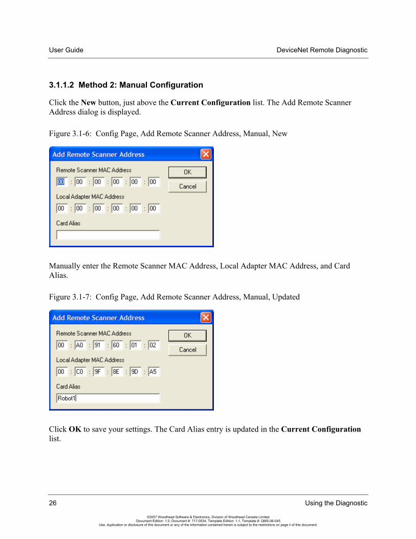
3.1.1.2 Method 2: Manual Configuration
Click the New button, just above the Current Configuration list. The Add Remote Scanner Address dialog is displayed.
Figure 3.1-6: Config Page, Add Remote Scanner Address, Manual, New
Manually enter the Remote Scanner MAC Address, Local Adapter MAC Address, and Card Alias.
Figure 3.1-7: Config Page, Add Remote Scanner Address, Manual, Updated
Click OK to save your settings. The Card Alias entry is updated in the Current Configuration list.

DeviceNet Remote Diagnostic User Guide
Using the Diagnostic 27
©2007 Woodhead Software & Electronics, Division of Woodhead Canada Limited Document Edition: 1.0, Document #: 717-0034, Template Edition: 1.1, Template #: QMS-06-045
Use, duplication or disclosure of this document or any of the information contained herein is subject to the restrictions on page ii of this document.
Figure 3.1-8: Config Page, Current Configuration, Manual, Updated
Note Changes to the current card name configuration will not take effect until the application is closed and re-opened.

User Guide DeviceNet Remote Diagnostic
28 Using the Diagnostic
©2007 Woodhead Software & Electronics, Division of Woodhead Canada Limited Document Edition: 1.0, Document #: 717-0034, Template Edition: 1.1, Template #: QMS-06-045
Use, duplication or disclosure of this document or any of the information contained herein is subject to the restrictions on page ii of this document.
3.1.2 Editing Remote DeviceNet Scanner Card Aliases
To change the Remote Scanner MAC Address, Local Adapter MAC Address, or Card Alias associated with a remote scanner, select the card in the Current Configuration list and click the Edit button. The Add Remote Scanner Address dialog is displayed.
Figure 3.1-9: Config Page, Add Remote Scanner Address, Edit
Update the fields and click OK to save your changes. The Card Alias entry will be updated in the Current Configuration list.
3.1.3 Removing Remote DeviceNet Scanner Card Aliases
To remove one or more card aliases from the DeviceNet Remote Scanner card name configuration, select the relevant cards in the Current Configuration list and click the Remove From Config button. The selected card aliases are deleted.

DeviceNet Remote Diagnostic User Guide
Using the Diagnostic 29
©2007 Woodhead Software & Electronics, Division of Woodhead Canada Limited Document Edition: 1.0, Document #: 717-0034, Template Edition: 1.1, Template #: QMS-06-045
Use, duplication or disclosure of this document or any of the information contained herein is subject to the restrictions on page ii of this document.
3.2 Auto-Detecting the Network In Auto-Detect Mode, the Diagnostic can be used to auto-detect DN network devices. This mode allows you to select which DN card will establish the network connection, as well as the baud rate and MAC ID. The Diagnostic then allows you to go online/scan.
To begin auto-detecting network devices, use the Auto-Detect Network Configuration command, via the Menu or Toolbar.
Network > Auto-Detect Network Configuration…
A dialog is then displayed, allowing you to select the name of the card to be used for auto-detection, the network baud rate and the scanner’s MAC ID. You can also set the scan interval and reconnect interval to be used by the master when going online (following auto-detection).
Figure 3.2-1: Scanner Settings for Auto-Detect Dialog

User Guide DeviceNet Remote Diagnostic
30 Using the Diagnostic
©2007 Woodhead Software & Electronics, Division of Woodhead Canada Limited Document Edition: 1.0, Document #: 717-0034, Template Edition: 1.1, Template #: QMS-06-045
Use, duplication or disclosure of this document or any of the information contained herein is subject to the restrictions on page ii of this document.
Click OK to begin auto-detecting the network. The dialog shown below is displayed during the detection process to indicate the status of the operation. Auto-detection involves opening the DN card, placing it online, searching for network devices and then returning the card to an offline state.
Figure 3.2-2: Auto-Detecting Network Configuration Dialog
Once detection is complete, the Configuration Tree View will display the detected network configuration (a master and one or more devices), and the Diagnostic title bar will indicate Auto-Detect Mode.
In this mode, you can go online, scan the devices and toggle the I/O idle state for any card listed in the Configuration Tree View. If any possible I/O connection types are detected, the first one, along with the detected I/O sizes, will be used when defining the configuration. This will be, in order, one of poll, strobe, COS, or cyclic. If you use the Go Online command, this configuration will be used. If you use the Go Online (Only Explicit Connections) command, the Diagnostic will establish only explicit connections with each of the detected devices.
Note If you want to detect and diagnose more than one network at once, run another instance of the Diagnostic and select a different card name.

DeviceNet Remote Diagnostic User Guide
Using the Diagnostic 31
©2007 Woodhead Software & Electronics, Division of Woodhead Canada Limited Document Edition: 1.0, Document #: 717-0034, Template Edition: 1.1, Template #: QMS-06-045
Use, duplication or disclosure of this document or any of the information contained herein is subject to the restrictions on page ii of this document.
3.3 Using the Active Console Configuration In Active Console Configuration Mode, the Diagnostic can open the current network configuration XML file created by the Console and load/parse the configuration data and topics within it. Once you have configured the DN network inside the DN Console and saved the configuration, you can open it in the Diagnostic. The Diagnostic will then configure the cards and allow you to go online/scan.
To open the network configuration, use the Open Current Console Network Configuration command, via the Menu or Toolbar.
File > Open Current Console Network Configuration
The Diagnostic will then open the configuration XML file generated by the Console and retrieve the configuration data for one or more cards, as defined in the file.
Once this is complete, the Configuration Tree View displays the configuration for each card: a master, server (if defined) and one or more devices. The Diagnostic title bar will indicate Active Console Configuration Mode.
In Active Console Configuration Mode, you can go online, scan devices and toggle the I/O idle state for any card listed in the Configuration Tree View.

User Guide DeviceNet Remote Diagnostic
32 Using the Diagnostic
©2007 Woodhead Software & Electronics, Division of Woodhead Canada Limited Document Edition: 1.0, Document #: 717-0034, Template Edition: 1.1, Template #: QMS-06-045
Use, duplication or disclosure of this document or any of the information contained herein is subject to the restrictions on page ii of this document.
3.4 Importing a Console Configuration File In File Mode, the Diagnostic can open an exported network configuration XML file (created by the Console) and load/parse the configuration data and topics within it. Once you have configured the DN network inside the DN Console and exported the configuration file to a different location than the currently active configuration folder, you can import the configuration file into the Diagnostic. The Diagnostic will then configure the cards and allow you to go online/scan.
Opening a Console-generated XML configuration file listed in the recent files list also places the Diagnostic in File Mode. The list of recent files is based on the recently imported network configuration files.
To open an exported network configuration, use the Import Console Network Configuration… command, via the Menu or Toolbar.
File > Import Console Network Configuration…
A dialog is displayed, allowing you to select the name of the configuration XML file to be opened. Clicking Open opens the configuration file and retrieves the configuration data for one or more cards, as defined in the file.
Once you have opened the configuration file, the Configuration Tree View displays the configuration data for each card: a master, server (if defined) and one or more devices. The Diagnostic title bar is updated with the name of the configuration file, to indicate that it is in File Mode.
In File Mode, you can go online, scan devices and toggle the I/O idle state for any card listed in the Configuration Tree View.

DeviceNet Remote Diagnostic User Guide
Using the Diagnostic 33
©2007 Woodhead Software & Electronics, Division of Woodhead Canada Limited Document Edition: 1.0, Document #: 717-0034, Template Edition: 1.1, Template #: QMS-06-045
Use, duplication or disclosure of this document or any of the information contained herein is subject to the restrictions on page ii of this document.
3.5 Viewing Network Information The Network Page (see Figure 3.5-1) displays information regarding the DN network, including the status of the scanner, server, CAN counters and bus. The network information for the card associated with the master, server, or device selected in the Configuration Tree View is shown.
The network information is divided into four sections: Scanner Status, Server Status, CAN Counters and Bus Status. A description of each field is provided below.
Table 3.5-1: Network Page Status Fields
Field Name Description Host Interface Memory Block Offset
Scanner Status
Online State The scanner “Online”/”Offline” status indicates whether the CAN interface has been initialized and is ready to communicate. A light is also displayed – light green if “Online”; gray otherwise.
0x30 – bit 0x01
Scan State The scanner “Scanning”/”Not scanning” status indicates the current status of the scanner’s client function. A light is also displayed – light green if “Scanning”; gray otherwise.
0x140 – bit 0x01
I/O Activity State The “I/O active”/”I/O idle” status indicates whether the scanner is transmitting Idle output messages (zero length, no data) to all devices in the scan list. A light is also displayed – light green if “I/O active”; gray otherwise. This field displays a status of “I/O idle” if the scanner is not scanning.
0x140 – bit 0x02
Baud Rate The baud rate of the network. This field is displayed only when the scanner is online.
0x30 – bit 0x1000, 0x2000, and 0x4000
Status Flags Reports the status of the scanner’s client function. 0x141
Event Status Scan event flags that inform the host of event occurrences related to the scanner’s client function.
0x142
Server Status
Configuration State The server “Configured”/”Not configured”/”Unknown” status. This field displays a status of “Configured” if the server exists in the configuration or if the Activity State is “Active”, or “Not configured” if a server does not exist in the configuration. A light is also displayed – light green if “Configured”; dark green if “Unknown”; gray otherwise.
0x160
Activity State The server “Idle”/”Active”/”Unknown” status indicates whether the Group 2 Master/Slave Connection Set is allocated for the scanner’s server function.
0x160
Status Flags Reports the status of the scanner’s server function. 0x161
Alloc. G2 Allocated G2 connection flags indicating the currently allocated Group 2 connections for the scanner module’s server function.
0x166
Event Status I/O event flags that inform the host of event occurrences related to the scanner’s server function.
0x162
Expl. Status Explicit request event flags that inform the host of event occurrences related to the server Explicit Request Message Buffer.
0x164

User Guide DeviceNet Remote Diagnostic
34 Using the Diagnostic
©2007 Woodhead Software & Electronics, Division of Woodhead Canada Limited Document Edition: 1.0, Document #: 717-0034, Template Edition: 1.1, Template #: QMS-06-045
Use, duplication or disclosure of this document or any of the information contained herein is subject to the restrictions on page ii of this document.
Field Name Description Host Interface
Memory Block Offset CAN Counters
Tx CAN transmit counter. Incremented when messages are submitted to the CAN controller.
0x32
Rx CAN receive counter. Incremented when messages are received. Messages that fail the receive filter still increment the receive counter.
0x36
No Ack. CAN ack error counter. Incremented when a transmit message is aborted due to lack of acknowledgement from other stations. When the ack error counter is incremented, the transmit counter is decremented to compensate for a message not actually transmitted.
0x34
Error CAN communication error counter. Incremented when a CAN frame error is detected.
0x38
Lost CAN lost messages counter. Incremented when a CAN message is received before the previous message is placed into the receive queue.
0x3A
Overrun CAN receive queue overrun counter. Incremented when a CAN message is lost due to a full receive queue.
0x3C
Bus Status
SA Scanner Active – at least one I/O or explicit connection is established. 0x30 – bit 0x8000
O5 Online at 500 kbaud. 0x30 – bit 0x4000
O2 Online at 250 kbaud. 0x30 – bit 0x2000
O1 Online at 125 kbaud. 0x30 – bit 0x1000
BP Bus Power Detect – bus power present (zero if power sense not supported). Indicates the presence or absence of network power. This flag is clear if the physical bus interface is not powered.
0x30 – bit 0x0200
ER CAN Bus Error – CAN communication error. This flag is set each time a CAN communication error is detected. An excessive number of errors indicates a faulty physical media component (cable, connector, etc.) or excessive noise from external sources (check cable routing and shield connection).
0x30 – bit 0x0100
ML Message Lost – CAN controller/receive ISR. This flag is set when a message is received from the bus while the previous message is still in the receive buffer. A lost message indicates a lower-layer application error (in the kernel interrupt handler).
0x30 – bit 0x80
RO Receive Buffer Overrun – host application too slow emptying receive queue. This flag is set when messages are received from the bus faster than the application can process them. An overrun receive buffer indicates an upper-layer application error (in the application module).
0x30 – bit 0x40
TO Transmit Timeout – transmit failed due to timeout (flooded network). This flag is set when a pending transmission is incomplete within 25-50ms. A transmit timeout indicates excessive message traffic at a higher priority than the aborted message.
0x30 – bit 0x20
TA Transmit Ack Error – transmit failed due to ack error (no other nodes connected). This flag is set when a pending transmission is not acknowledged within 25-50ms. A transmit ack error indicates that no other nodes are present (or online) on the network.
0x30 – bit 0x10

DeviceNet Remote Diagnostic User Guide
Using the Diagnostic 35
©2007 Woodhead Software & Electronics, Division of Woodhead Canada Limited Document Edition: 1.0, Document #: 717-0034, Template Edition: 1.1, Template #: QMS-06-045
Use, duplication or disclosure of this document or any of the information contained herein is subject to the restrictions on page ii of this document.
Field Name Description Host Interface
Memory Block Offset A Network Activity Detected – messages received or transmitted. This flag
is set when any message is transmitted or received. 0x30 – bit 0x08
BO Bus Off – the node has been disconnected due to excessive errors. This flag is set when an excessive number of communication errors are detected and the CAN chip automatically goes offline. This flag is cleared when the CAN interface is reinitialized. A bus off condition indicates a serious communication fault, such as an incorrect baud rate or physical layer error (short, open, etc.). To recover from a bus off condition, the application can issue the following command sequence: stop scan, offline, online, start scan.
0x30 – bit 0x04
BW Bus Warning – the node is experiencing a large number of errors. This flag is set when an abnormal number of communication errors are detected and the CAN chip stops transmitting error frames. This flag is cleared when the error count returns to normal levels or the CAN interface is reinitialized. A bus warning indicates a potentially serious communication fault such as an out-of-tolerance baud rate or physical layer error (electrical noise, signal attenuation, intermittent connection, etc.).
0x30 – bit 0x02
OL Online – CAN interface has been initialized and is ready to communicate.
0x30 – bit 0x01

User Guide DeviceNet Remote Diagnostic
36 Using the Diagnostic
©2007 Woodhead Software & Electronics, Division of Woodhead Canada Limited Document Edition: 1.0, Document #: 717-0034, Template Edition: 1.1, Template #: QMS-06-045
Use, duplication or disclosure of this document or any of the information contained herein is subject to the restrictions on page ii of this document.
Figure 3.5-1: Network Page

DeviceNet Remote Diagnostic User Guide
Using the Diagnostic 37
©2007 Woodhead Software & Electronics, Division of Woodhead Canada Limited Document Edition: 1.0, Document #: 717-0034, Template Edition: 1.1, Template #: QMS-06-045
Use, duplication or disclosure of this document or any of the information contained herein is subject to the restrictions on page ii of this document.
3.6 Viewing Card Information The Card Page (see Figure 3.6-1) displays information regarding the status of the DN card, scanner module and application kernel. The status information for the card associated with the master, server or device selected in the Configuration Tree View will be shown.
The card information is divided into three sections: Card, Module and Kernel. A description of each field is provided below.
Table 3.6-1: Card Page Status Fields
Field Name Description Host Interface Memory Block Offset
Card
Card Type Type of card (e.g., SST-DN3-PCI-2). 0x12
Serial No. Card serial number. 0x22
DeviceNet Serial No. DeviceNet serial number. 0x0E
Module
Type Type of module loaded onto the card. This field displays “DN” or “ER” if a kernel error is detected.
0x00
ID Module identification number. 0x0A
Revision Module revision number. 0x0C
Main App. Error Code Module main application error code. 0x2E
Add. App. Error Code Module additional application error code. 0x3E
Name Module identification string. This field will be empty if the module type is “ER” (which indicates a kernel error).
0x40
Kernel
ID Kernel identification number. 0x06
Revision Kernel revision number. 0x08
Irq. Control Reports the status of the card interrupt control flags, which are used to enable the generation of a physical interrupt for each of up to 8 logical interrupt sources.
0x2A
Irq. Status A Reports the state of the card interrupt flags, which are set when each of up to 8 logical interrupts occur.
0x2C
Irq. Status B Reports the state of the card interrupt flags, which are set when each of up to 8 logical interrupts occur.
0x2D
Status Kernel error string. A light is also displayed – light green if no errors were detected; red otherwise. This field is applicable only when the module type is “ER” (which indicates a kernel error). Otherwise, this field displays “No errors detected”.
0x40

User Guide DeviceNet Remote Diagnostic
38 Using the Diagnostic
©2007 Woodhead Software & Electronics, Division of Woodhead Canada Limited Document Edition: 1.0, Document #: 717-0034, Template Edition: 1.1, Template #: QMS-06-045
Use, duplication or disclosure of this document or any of the information contained herein is subject to the restrictions on page ii of this document.
Figure 3.6-1: Card Page
DeviceNet Remote Diagnostic User Guide
Using the Diagnostic 39
©2007 Woodhead Software & Electronics, Division of Woodhead Canada Limited Document Edition: 1.0, Document #: 717-0034, Template Edition: 1.1, Template #: QMS-06-045
Use, duplication or disclosure of this document or any of the information contained herein is subject to the restrictions on page ii of this document.
3.7 Viewing the Master, Server, and Device Configuration The Device Page (see Figures 3.7-1, 3.7-2, and 3.7-3) displays the configuration data for the master, server and devices on a DN network. The configuration data specific to the item selected in the Configuration Tree View will be shown.
3.7.1 Master or Server Selected
When a master or server is selected, the master/scanner settings or server configuration (if any) will be displayed in the Status field.
Note No server will be displayed in the Configuration Tree View when the Diagnostic is in Auto-Detect Mode.
When a master is selected, the status is obtained from the Client Status Block (host interface memory block, at offset 0x140). The status will be “Idle (not scanning)” if bit 0x01 is clear. Otherwise, it will be “Active (scanning); Tx Idle (I/O not active)” if bit 0x02 is set, or “Active (scanning); I/O active” if bit 0x02 is clear. A light is also displayed: light green if the client is scanning; dark green otherwise.
When a server is selected, the status is obtained from the Server Status Block (host interface memory block offset 0x160). The status will be “Idle (Group 2 Master/Slave Connection Set not allocated)” if the status byte is 0x00, “Active (Group 2 Master/Slave Connection Set allocated)” if the status byte is 0x01 or “Unknown” otherwise. A light is also displayed: light green if the server is active, dark green if the server is idle, and yellow if the server status is unknown.
The MAC ID associated with the master/scanner is displayed, along with the network baud rate defined in the configuration. Additionally, the scan interval (default I/O update interval used for strobe and poll I/O connections with an I/O interval of 0) and the reconnect interval (period to wait before attempting to reconnect when a connection to a device is lost) associated with the master are shown.

User Guide DeviceNet Remote Diagnostic
40 Using the Diagnostic
©2007 Woodhead Software & Electronics, Division of Woodhead Canada Limited Document Edition: 1.0, Document #: 717-0034, Template Edition: 1.1, Template #: QMS-06-045
Use, duplication or disclosure of this document or any of the information contained herein is subject to the restrictions on page ii of this document.
The server configuration data is also provided. This includes:
• The server connection flags
• The I/O connection update intervals
• The explicit connection request and response buffer sizes and offsets
• The I/O connection input and output buffer sizes and offsets
Figure 3.7-1: Device Page in Auto-Detect Mode, Master Selected

DeviceNet Remote Diagnostic User Guide
Using the Diagnostic 41
©2007 Woodhead Software & Electronics, Division of Woodhead Canada Limited Document Edition: 1.0, Document #: 717-0034, Template Edition: 1.1, Template #: QMS-06-045
Use, duplication or disclosure of this document or any of the information contained herein is subject to the restrictions on page ii of this document.
3.7.2 Device Selected – Auto-Detect Mode
In Auto-Detect Mode, the Status field will reflect the status of the selected device, as obtained from the Device Status Table (host interface memory block offset 0x1C0 + 16 * MAC ID). Refer to the DN Scanner Module 32-Bit DLL API Reference Guide for a list of possible error codes and their meaning. A light is also displayed: light gray if the device is not in the device list, dark green if the device is idle, light green if the device is scanning and red if the device is in error.
The MAC ID associated with the device is displayed, along with the product name, vendor ID, device type, product code, serial number and major and minor revision numbers.
The configuration data for the detected device is also provided. This includes the explicit connection request buffer size and offset, as well as the in-use and potential I/O connection settings.
If any I/O connection types are detected, the first one, along with the detected I/O sizes, will be used when defining the configuration. This will be, in order, one of poll, strobe, COS, or cyclic. If you use the Go Online command, this configuration will be used. If you use the Go Online (Only Explicit Connections) command, then the Diagnostic will establish explicit connections only with each of the detected devices. This configuration is displayed in the Device page’s I/O Connection 1 section. The other potential connections and I/O sizes are displayed in the Device page's Other Connections section.
Note The COS and cyclic I/O connections always have the same input and output sizes.

User Guide DeviceNet Remote Diagnostic
42 Using the Diagnostic
©2007 Woodhead Software & Electronics, Division of Woodhead Canada Limited Document Edition: 1.0, Document #: 717-0034, Template Edition: 1.1, Template #: QMS-06-045
Use, duplication or disclosure of this document or any of the information contained herein is subject to the restrictions on page ii of this document.
Figure 3.7-2: Device Page in Auto-Detect Mode, Device Selected

DeviceNet Remote Diagnostic User Guide
Using the Diagnostic 43
©2007 Woodhead Software & Electronics, Division of Woodhead Canada Limited Document Edition: 1.0, Document #: 717-0034, Template Edition: 1.1, Template #: QMS-06-045
Use, duplication or disclosure of this document or any of the information contained herein is subject to the restrictions on page ii of this document.
Figure 3.7-3: Device Page in Auto-Detect Mode, Device Selected, Only Explicit Connections

User Guide DeviceNet Remote Diagnostic
44 Using the Diagnostic
©2007 Woodhead Software & Electronics, Division of Woodhead Canada Limited Document Edition: 1.0, Document #: 717-0034, Template Edition: 1.1, Template #: QMS-06-045
Use, duplication or disclosure of this document or any of the information contained herein is subject to the restrictions on page ii of this document.
3.7.3 Device Selected – Other Than Auto-Detect Mode
If a device is selected while in a mode other than Auto-Detect, the Status field will reflect the detected device’s status, as obtained from the Device Status Table (host interface memory block offset 0x1C0 + 16 * MAC ID). Refer to the DN Scanner Module 32-Bit DLL API Reference Guide for a list of error codes and their meaning. A light is also displayed: light gray if the device is not in the device list, dark green if the device is idle, light green if the device is scanning and red if the device is in error.
The device’s MAC ID is displayed, along with the vendor ID, device type, product code and production inhibit time (only applicable to COS connections).
The device configuration data is also provided. This includes:
• The device connection flags
• The I/O connection update intervals
• The explicit connection request buffer size and offset
• The I/O connection input and output buffer sizes and offsets for each of the two possible connections

DeviceNet Remote Diagnostic User Guide
Using the Diagnostic 45
©2007 Woodhead Software & Electronics, Division of Woodhead Canada Limited Document Edition: 1.0, Document #: 717-0034, Template Edition: 1.1, Template #: QMS-06-045
Use, duplication or disclosure of this document or any of the information contained herein is subject to the restrictions on page ii of this document.
Figure 3.7-4: Device Page in Active Console Configuration Mode, Device Selected

User Guide DeviceNet Remote Diagnostic
46 Using the Diagnostic
©2007 Woodhead Software & Electronics, Division of Woodhead Canada Limited Document Edition: 1.0, Document #: 717-0034, Template Edition: 1.1, Template #: QMS-06-045
Use, duplication or disclosure of this document or any of the information contained herein is subject to the restrictions on page ii of this document.
3.8 Viewing and Changing the Device and Server I/O Data The I/O 1 and I/O 2 pages (see Figure 3.8-1) display and allow changes to the I/O data for the DN network’s server and devices. The I/O 1 page is associated with the device’s first connection, and the I/O 2 page is associated with the second connection. The I/O data specific to the device or server selected in the Configuration Tree View will be shown.
The upper data display grid is read-only and contains the current input data of the selected device, or the current output data of the selected server. The lower data display grid is editable and contains the current output data for the selected device, or the current input data for the selected server. Also displayed is the number of bytes of data associated with these data grids and the MAC ID of the server or device selected in the Configuration Tree View.
Selecting Use Device Offsets allows you to specify whether to use the device offsets when displaying the numerical row names in the grids or just offsets of 0 (within the input or output buffer).
Note This setting affects both the I/O 1 and I/O 2 pages.
The lower section of the page is used to control the automatic generation of values (device outputs or server inputs). The method used to generate the values can be one of “Tx+1” (each byte of outgoing data = each byte of outgoing data + 1), “Rx to Tx” (each byte of outgoing data = each byte of incoming data) or “Rx+1 to Tx” (each byte of outgoing data = each byte of incoming data + 1). The interval at which the auto-generation of values occurs can be specified as a value between 10 and 60000 ms.
Click Start to begin generating outgoing values automatically. The relevant device or server’s MAC ID will be shown, and a light will also be displayed: light green while values are being generated; light gray otherwise. Click Stop to end the process.
Note Only one device or server can have its outgoing values auto-generated for each of the two I/O connections. For example, you can auto-generate values for I/O connection 1 and 2 of device 26, or values for I/O connection 1 of device 26 and I/O connection 2 of a different device or a server, but you cannot auto-generate values for I/O connection 1 of two different devices or a server at the same time.

DeviceNet Remote Diagnostic User Guide
Using the Diagnostic 47
©2007 Woodhead Software & Electronics, Division of Woodhead Canada Limited Document Edition: 1.0, Document #: 717-0034, Template Edition: 1.1, Template #: QMS-06-045
Use, duplication or disclosure of this document or any of the information contained herein is subject to the restrictions on page ii of this document.
Figure 3.8-1: I/O 1 Page
User Guide DeviceNet Remote Diagnostic
48 Using the Diagnostic
©2007 Woodhead Software & Electronics, Division of Woodhead Canada Limited Document Edition: 1.0, Document #: 717-0034, Template Edition: 1.1, Template #: QMS-06-045
Use, duplication or disclosure of this document or any of the information contained herein is subject to the restrictions on page ii of this document.
3.9 Sending Explicit Messages to a Device The Send Explicit Page (see Figure 3.9-1) allows explicit messages to be sent to DN network devices.
The messages will be sent to the selected device’s MAC ID. The service, class, instance, and service data (which includes any attribute) of the relevant message can be entered. The service and class can also be selected from the corresponding list of available codes. The service data must be entered in hexadecimal format, which consists of up to 256 byte values, optionally separated by spaces. For example, “000a1200cc”, “00 0a 12 00 cc”, and “0 0a 12 0 cc” all specify valid service data.
The middle-left section of the page is used to send one or more explicit messages to the selected device. The number of times the explicit message should be sent can be specified as a value between 1 and 1000. Click Send to send the defined explicit message.
The middle-right section of the page is used to control the automatic sending of explicit messages. The interval at which auto-sending occurs can be specified as a value between 10 and 60000 ms. Click Start to begin generating outgoing values automatically. The relevant device’s MAC ID will be shown, and a light is also displayed: light green when explicit messages are being sent; light gray otherwise.
Note Explicit messages can only be sent to one device at a time. Click Stop to end the process.
All responses (to both manual and auto-generated explicit messages) will be displayed in the history window at the bottom of the page, with the most recent responses listed first. You can clear the history anytime by clicking Clear. The message count is also displayed. This is reset each time Send or Start is clicked or the history is cleared.

DeviceNet Remote Diagnostic User Guide
Using the Diagnostic 49
©2007 Woodhead Software & Electronics, Division of Woodhead Canada Limited Document Edition: 1.0, Document #: 717-0034, Template Edition: 1.1, Template #: QMS-06-045
Use, duplication or disclosure of this document or any of the information contained herein is subject to the restrictions on page ii of this document.
Figure 3.9-1: Send Explicit Page

User Guide DeviceNet Remote Diagnostic
50 Using the Diagnostic
©2007 Woodhead Software & Electronics, Division of Woodhead Canada Limited Document Edition: 1.0, Document #: 717-0034, Template Edition: 1.1, Template #: QMS-06-045
Use, duplication or disclosure of this document or any of the information contained herein is subject to the restrictions on page ii of this document.

DeviceNet Remote Diagnostic User Guide
Warranty and Support 51
©2007 Woodhead Software & Electronics, Division of Woodhead Canada Limited Document Edition: 1.0, Document #: 717-0034, Template Edition: 1.1, Template #: QMS-06-045
Use, duplication or disclosure of this document or any of the information contained herein is subject to the restrictions on page ii of this document.
A Warranty and Support
Appendix Sections:
• Warranty
• Technical Support

User Guide DeviceNet Remote Diagnostic
52 Warranty and Support
©2007 Woodhead Software & Electronics, Division of Woodhead Canada Limited Document Edition: 1.0, Document #: 717-0034, Template Edition: 1.1, Template #: QMS-06-045
Use, duplication or disclosure of this document or any of the information contained herein is subject to the restrictions on page ii of this document.
A.1 Warranty For software warranty information, refer to http://www.mysst.com/warranty.asp.
A.2 Technical Support Please ensure that you have the following information readily available before calling for technical support:
• Software version
• Computer’s make, model, CPU speed and hardware configuration (other cards installed)
• Operating system type and version
• Details of the problem you are experiencing: application module type and version, target network, and circumstances that may have caused the problem

DeviceNet Remote Diagnostic User Guide
Warranty and Support 53
©2007 Woodhead Software & Electronics, Division of Woodhead Canada Limited Document Edition: 1.0, Document #: 717-0034, Template Edition: 1.1, Template #: QMS-06-045
Use, duplication or disclosure of this document or any of the information contained herein is subject to the restrictions on page ii of this document.
A.2.1 Getting Help
Technical support is available during regular business hours by telephone, fax or email from any Woodhead Software & Electronics office, or from http://www.woodhead.com. Documentation and software updates are also available on the Web site.
North America
Canada: Tel: 1-519-725-5136 Fax: 1-519-725-1515 Email: [email protected]
Europe
France: Tel: 33-(0)2-32-96-04-22 Fax: 33-(0)2-32-96-04-21 Email: [email protected]
Germany: Tel: 49-711-782-374-22 Fax: 49-711-782-374-11 Email: [email protected]
Italy: Tel: 39-010-595-4052 Fax: 39-010-595-6925 Email: [email protected]
Other countries: Tel: 33-(0)2-32-96-04-23 Fax: 33-(0)2-32-96-04-21 Email: [email protected]

User Guide DeviceNet Remote Diagnostic
54 Warranty and Support
©2007 Woodhead Software & Electronics, Division of Woodhead Canada Limited Document Edition: 1.0, Document #: 717-0034, Template Edition: 1.1, Template #: QMS-06-045
Use, duplication or disclosure of this document or any of the information contained herein is subject to the restrictions on page ii of this document.
Asia-Pacific
Japan: Tel: 81-3-5791-4621 Fax: 81-3-5791-4688 Email: [email protected]
Singapore: Tel: 65-6261-6533 Fax: 65-6261-3588 Email: [email protected]
China: Tel: 86-21-5835-9885 Fax: 86-21-5835-9980 Email: [email protected]
For the most current contact details, please visit http://www.woodhead.com.

DeviceNet Remote Diagnostic User Guide
Index 55
©2007 Woodhead Software & Electronics, Division of Woodhead Canada Limited Document Edition: 1.0, Document #: 717-0034, Template Edition: 1.1, Template #: QMS-06-045
Use, duplication or disclosure of this document or any of the information contained herein is subject to the restrictions on page ii of this document.
Index
A Active Console Configuration Mode
described, 11 using, 31
Add App. Error Code field, 37 alias. See Card Alias Auto-Detect Mode, 11, 29, 41
C capabilities of Remote Diagnostic, 10 card alias
adding manually, 26 adding to Remote Scanner, 20 configuring, 20 editing, 28 function of, 20 removing, 28 searching for, 21
card information, viewing, 37 card name. See card alias Card Type field, 37 changing device I/O data, 46 changing server I/O data, 46 configuration data, loading and parsing, 31
Configuration Tree View, location and function of, 15
console configuration file, importing, 32 Console, defined, vii conventions used in this guide
special notation, vii special terms, vii style, vi
D device configuration, viewing, 39 device I/O data
changing, 46 viewing, 46
device, selecting, 41, 44 device, sending explicit messages to, 48 DeviceNet Serial No. field, 37 Diagnostic, defined, vii
E editing card aliases, 28 explicit messages, sending, 48

User Guide DeviceNet Remote Diagnostic
56 Index
©2007 Woodhead Software & Electronics, Division of Woodhead Canada Limited Document Edition: 1.0, Document #: 717-0034, Template Edition: 1.1, Template #: QMS-06-045
Use, duplication or disclosure of this document or any of the information contained herein is subject to the restrictions on page ii of this document.
F features of Remote Diagnostic, 10 File Mode, 11
I I/O data
changing, 46 viewing, 46
importing a console configuration file, 32 Irq Control field, 37 Irq Status A field, 37 Irq Status B field, 37
K Kernel ID field, 37 Kernel Revision Field, 37
M Main App. Error Code field, 37 master configuration, viewing, 39 master, selecting, 39 Menu Bar items, 16 Menu Bar, location and function of, 14 Module ID field, 37 Module Revision field, 37
N
Name field, 37 network information, viewing, 33 network, auto-detecting, 29 note, defined, vii numerical values, entering, 17
O overview of Remote Diagnostic, 14
P Property Pages, location and function of, 15 purpose of this guide, vi
R Remote Diagnostic
auto-detecting network with, 29 capabilities of, 10 configuring card aliases for, 20 entering numerical values in, 17 general overview of, 14 guidelines for use, 11 importing a configuration file with, 32 system requirements for, 11 using Active Configuration Mode with, 31 viewing card information with, 37 viewing network information with, 33
Remote Scanner, adding card aliases to, 20 removing card aliases, 28
S selecting a device, 41, 44 selecting a master or server, 39 sending explicit messages, 48 Serial No. field, 37 server configuration, viewing, 39 server I/O data
changing, 46 viewing, 46
server, selecting, 39 Status Bar, location and function of, 15 Status field, 37 support, 52 system requirements for Diagnostic, 11
T Technical Support, 52 Toolbar items, 16 Toolbar, location and function of, 14 Type field, 37

DeviceNet Remote Diagnostic User Guide
Index 57
©2007 Woodhead Software & Electronics, Division of Woodhead Canada Limited Document Edition: 1.0, Document #: 717-0034, Template Edition: 1.1, Template #: QMS-06-045
Use, duplication or disclosure of this document or any of the information contained herein is subject to the restrictions on page ii of this document.
V viewing card information, 37 viewing device configurations, 39 viewing device I/O data, 46 viewing network information, 33
viewing server I/O data, 46
W warranty, 52