device: plt-1001 this document version: 2.0 for hardware ... · ... led matrix display driver board...
TRANSCRIPT

Device: PLT-1001
This document Version: 2.0
For hardware Version: 4
Date: June 2012
Description: LED Matrix Display Driver board

PLT-1001v4 datasheet – Page 2
www.embeddedadventures.com
Table of Contents
Introduction......................................................................................................... 3
Features .............................................................................................................. 3
Hackability ........................................................................................................... 3
Construction ........................................................................................................ 3
Connections ......................................................................................................... 4
Power ................................................................................................................. 4
Buttons ............................................................................................................... 8
Schematic.......................................................................................................... 10
Microcontroller................................................... Error! Bookmark not defined.
Real Time Clock (RTC) and Temperature Sensor .. Error! Bookmark not defined.
MRF24J40MB ..................................................... Error! Bookmark not defined.
Other connections ............................................. Error! Bookmark not defined.
PCB ................................................................................................................... 12
Versions ............................................................................................................ 12

PLT-1001v4 datasheet – Page 3
www.embeddedadventures.com
Introduction
The PLT-1001v4 is a Microchip PIC18F26K22 based driver board designed to drive dynamically-scanned LED matrix displays (LED display panels) such as the LDP-6408, LDP-8008, LDP-6416 and LDP-6432 from Embedded Adventures. Other panels that have similar pin-outs will work as well. Other panels that have different pin-outs but work the same way, will work with a little jumper wiring.
You don’t need to know anything about the microcontroller on board to use the driver board however – it takes simple commands over the TTL serial port to enable rich graphical displays on common LED matrix display panels. Of course, if you want to, you can completely hack the firmware to change it in any way you like, but this is not necessary for normal operation.
Features
The PLT-1001 is designed to make it easy to interface to LED matrix displays. These displays require constant updating which consumes microcontroller CPU. This driver board allows graphical and text functions to be displayed through simple serial commands.
Hackability
The PLT-1001 is 100% hackable.
At Embedded Adventures, we believe you have the most fun when you have the most control over your hardware. For the PLT-1001 we provide a datasheet, complete schematic and complete source code. After that, it’s all up to you. We’d love to hear about the projects you’re using it for – send us information and photos to [email protected]
Construction
The PLT-1001v4 can be back-pack connected to LDP-6408 or LDP-8008 displays by soldering an 8x2 0.1” female connector on the underside of the board (so the pins are soldered on top).
It can be back-pack connected to LDP-6416 or LDP-6432, or alternatively a male connector can be soldered to the top side of the board and the supplied IDC cable can be used to connect to the display.
For power, the PLT-1001 requires 5V and ground connections. Solder the terminal connectors on the board for easy screw connections.

PLT-1001v4 datasheet – Page 4
www.embeddedadventures.com
Connections
The PLT-1001 has five connection ports. The breakout ports will be used for future expansion. The ICSP port is used for reprogramming the driver board using a PicKit or similar, but is not required for normal use.
TTL SERIAL TTL level serial port ICSP Programming port for PIC, RB6, RB7 connections
Breakout 1 Breakout pins GND, RB0, RB1, RB2, +5V Breakout 2 RB3, RB5, RC1, RC4, RC5, GND LEDPANEL 16 pin connection to LED display panel
Power
The PLT-1001 provides a terminal block for power input for connection to your LED matrix display(s). The PLT-1001 is designed to run at 5v. Note that running large quantities of LEDs can result in a voltage drop across the supply, which may affect the reliability of the microcontroller. See the datasheet for your LED matrix display.
Setup
The PLT-1001 comes with firmware for the LDP-8008 board. For other boards you will need to update the firmware.
Updating the firmware is easy!
Download the appropriate .hex file from the Embedded Adventures product page that matches your board.
Download the screamer bootloader application from the Tutorials | Downloads section of the web site also.
Connect a TTL serial port to your PC, like a USB to Serial PLT-1003. Connect TX from your TTL serial port to RX-I on the PLT-1001, and RX on your serial port to TX-O on the PLT-1001, and GND to both devices. The PLT-1001 will need to be powered with 5V if it can’t get this from your serial port device.
Set the COM port setting to your COM port Set the Baud rate to 115,200 Press Open and choose the .hex file appropriate to your LED matrix display. Press Download, and then reset the PLT-1001 by pressing the reset button. The new firmware will then be downloaded to the PLT-1001.

PLT-1001v4 datasheet – Page 5
www.embeddedadventures.com
Operation
The driver board is controlled by the TTL Serial port. Connect a device to TxO and RxI – keeping in mind that you will need to connect transmit on your device to RxI on the PLT-1001, and receive on your device to TxO on the PLT-1001.
Set your serial port to 115,200bps and then you’re ready to issue some commands.
Commands
The driver is double buffered. There is a “draw” buffer, which is what these commands act on, and a “display” buffer which unsurprisingly is what is actually used to drive the display.
This means that you can set up exactly what you need on the screen using multiple commands and then transfer the entire completed picture to the actual display in one hit for very smooth updates.
The driver board comes with a collection of graphical and text commands. Each command starts with a text word and ends with <ENTER> (#13).
Once you have sent all commands you need, send a paint command. Effectively the paint command copies the draw buffer to the display buffer.
The exceptions to this are the scroll command, which doesn’t require paint, since it updates the buffer automatically as the text moves across the display, and the test command.
Parameters to the commands can be separated by commas or spaces.
Most LED matrix displays, at least the ones from Embedded Adventures, have two pixel colours available - red and green, giving you black (colour 0), red (colour 1), green (colour 2), orange (colour 3).
clear
clear
Clear the display (all black pixels)
pixel
pixel colour x y
Set the pixel at position x, y to the specified colour.

PLT-1001v4 datasheet – Page 6
www.embeddedadventures.com
line
line colour x1 y1 x2 y2
Draws a line between x1, y1 and x2, y2 in the specified colour.
rect
rect colour x y width height
Draws a rectangle with left, bottom corner x,y that is width wide and height high.
circle
circle colour x_centre y_centre radius
Draws a circle centred at x_centre, y_centre in the specified radius and colour.
circlef
circlef colour x_centre y_centre radius
Draws a filled circle centred at x_centre, y_centre in the specified radius and colour.
circle2
circle2 colour x_centre y_centre radius
Draws a “squared” circle, centred at x_centre, y_centre – like an ordinary circle but with an extra pixel inserted at the top and sides so that the circle completely fills a square space.
font
font font_num
Sets the current font to font_num. The fonts are as follows:
1 – 5 pixel high (narrow)
2 – 5 pixel high (normal)
3 – 7 pixel high (normal)
4 – 8 pixel high (normal)
5 – 16 pixel high (double width)
6 – 16 pixel high (triple width)

PLT-1001v4 datasheet – Page 7
www.embeddedadventures.com
text
text colour x y "text"
Displays text in the current font where the bottom left corner of the text is positioned at x,y.
scroll
scroll colour x y width "text"
Displays text that scrolls through the rectangle made by x,y to width and the font height.
paint
paint
Copies the draw buffer to the display buffer so previous commands are actually displayed.
Test commands
test test_num
A series of test commands are available to confirm that everything is working, this is especially handy when working with a new board or when developing drivers for a new board.
Test Result 0 Top left pixel 1 Top right pixel 2 Bottom right pixel 3 Bottom left pixel 4 Full screen, colour 1 5 Full screen, colour 2 6 Full screen, colour 3 7 Circle, full height, centred 8 Rectangle 1 pixel in from the edge, colour 1 9 Rectangle 2 pixel in from the edge, colour 1 10 Rectangle 3 pixel in from the edge, colour 1 11 Lines around the edge 12 Static text 13 8 pixel high bitmap 14 16 pixel high bitmap (if display is big enough) 15 32 pixel high bitmap (if display is big enough)

PLT-1001v4 datasheet – Page 8
www.embeddedadventures.com
Tips and tricks
I’m sending commands but nothing is displayed!
Check the power connections. Be careful when hooking up the board since reversing the connections will damage LED matrix displays.
Make sure you send a paint command after you send commands.
Check that your panel has the same pin-out as the PLT-1001 – if not, see the section on using the PLT-1001 with other panels.
The firmware will print out its version when the PLT-1001 is reset, so check that the right firmware for the display is loaded.
I’m sending commands and there’s crazy stuff being displayed!
The firmware is designed to be small and fast – so it often avoids parameter checks.
Most likely if you’re seeing strange things displayed, one of your parameters is out of spec.
For example, if you are using an LDP-8008, remember that the vertical pixels (y dimension) are numbered 0 through 7. Setting a pixel at x=0, y=8 will set a random area of memory rather than what you expect. Of course this is amplified when using commands that use large areas of the screen. Check your parameters to make sure that you are within the spec of the screen you are using. Set a pixel at x=0, y=7 instead.
Something else to be conscious of is that the commands that take x, y parameters specify the bottom left corner of the function, and the x=0, y=0 pixel is in the top left hand corner of the display. So to display a full screen red rectangle on an LDP-8008, you would issue the commands:
rect 1 0 7 80 8
paint
(where 1 = red, x=0, y=7 (bottom left corner), 80 pixels wide, 8 pixels high.
Buttons
The PLT-1001 has a reset button, which is in fact connected to RE3 (MCLR). You may decide that is more useful to actually have a functioning push button. In this case, you will need to change the config fuses so that the pin functions as RE3 and not MCLR. Please see the PIC18F26k22 datasheet for more information.
PLT-1001v4 datasheet – Page 9
www.embeddedadventures.com
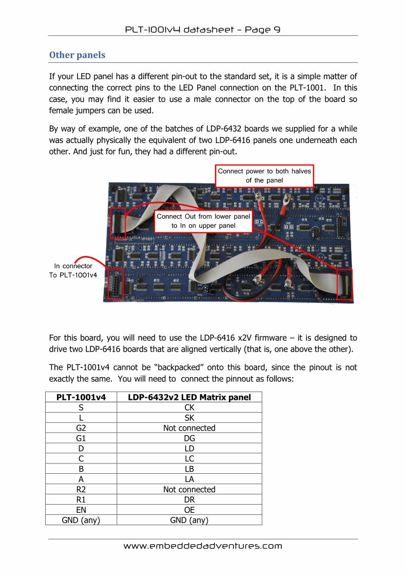
Other panels
If your LED panel has a different pin-out to the standard set, it is a simple matter of connecting the correct pins to the LED Panel connection on the PLT-1001. In this case, you may find it easier to use a male connector on the top of the board so female jumpers can be used.
By way of example, one of the batches of LDP-6432 boards we supplied for a while was actually physically the equivalent of two LDP-6416 panels one underneath each other. And just for fun, they had a different pin-out.
For this board, you will need to use the LDP-6416 x2V firmware – it is designed to drive two LDP-6416 boards that are aligned vertically (that is, one above the other).
The PLT-1001v4 cannot be “backpacked” onto this board, since the pinout is not exactly the same. You will need to connect the pinnout as follows:
PLT-1001v4 LDP-6432v2 LED Matrix panel S CK L SK
G2 Not connected G1 DG D LD C LC B LB A LA R2 Not connected R1 DR EN OE
GND (any) GND (any)

PLT-1001v4 datasheet – Page 10
www.embeddedadventures.com
Schematic
General circuit
The microcontroller circuitry is fairly standard. A reset button is provided, which pulls MCLR to ground. C1 prevents debounce noise. C2, C3 and crystal Q3 allow the PIC to run at 16mips. LED1 is available by pulling RA0 high; it is used by the 18f26K22_16Mhz_64Mhz_PLL version of Boostbloader to indicate the bootloader is alive and well. C4 is a power supply bypass for the PIC and the ICSP connection provides a way of reprogramming the PIC without a bootloader (or to flash a new bootloader).
Connections
The LED panel connection follows the standard connection for LED matrix display panels.
The TTL serial connection allows for control of the PLT-1001.

PLT-1001v4 datasheet – Page 11
www.embeddedadventures.com
The other connections break out remaining pins on the microcontroller for future expansion.
A previous version of the PLT-1001 board contained a real time clock and temperature sensor, however to reduce the size of the board to allow the backpack configuration (and reduce the cost of the board!), these were removed from this version. However other modules can be connected to the PLT-1001 using these breakout connections.
In future updates to the firmware we’ll enable other modules to be connected to the PLT-1001v4.

PLT-1001v4 datasheet – Page 12
www.embeddedadventures.com
PCB
Versions
Version Date Comments Version 1.0 9 June 2010 Initial version for board v1.2 Version 2.0 16 June 2012 Updated version for the completely revamped v4