device having the same foreign patent documents · 92305 describes an anti-reflection film which...
TRANSCRIPT
USOO59 19555A
United States Patent (19) 11 Patent Number: 5,919,555 Yasuda et al. (45) Date of Patent: Jul. 6, 1999
54). ANTI-REFLECTION FILM AND DISPLAY 5,225,244 7/1993 Aharoni et al. ......................... 427/240 DEVICE HAVING THE SAME
75 Inventors: Tomokazu Yasuda; Tsukasa Yamada; Hirohisa Hokazono, all of Kanagawa, Japan
73 Assignee: Fuji Photo Film Co., Ltd., Minami-Ashigara, Japan
21 Appl. No.: 08/964,112
22 Filed: Nov. 5, 1997 30 Foreign Application Priority Data
Nov. 6, 1996 JP Japan .................................... 8-294241 May 19, 1997 JP Japan .................................... 9-128993
(51) Int. Cl. .................................................. B32B 9/00 52 U.S. Cl. .......................... 428/206; 428/143; 428/147;
428/308.4; 428/314.8; 428/409; 428/411.1; 428/412; 428/421; 428/422; 428/423.7;
427/71; 427/202; 427/163.1; 427/165; 359/580; 359/582; 359/589
58 Field of Search ..................................... 428/143, 147, 428/421, 422, 308.4, 206, 411.1, 314.8,
423.7, 412,409; 359/609, 589, 582, 580, 601; 427/71, 163.1, 165, 202, 203, 164
56) References Cited
U.S. PATENT DOCUMENTS
4,904,525 2/1990 Taniguchi et al. ...................... 428/328
41
CO C=OCs 9COOC(OCX59 SC3, SSC 9 Cz N &
FOREIGN PATENT DOCUMENTS
7-92305 TO92305
4/1995 Japan. 4/1995 Japan.
Primary Examiner William Krynski ASSistant Examiner Abraham Bahta
Attorney, Agent, or Firm-Burns, Doane, Swecker & Mathis, LLP
57 ABSTRACT
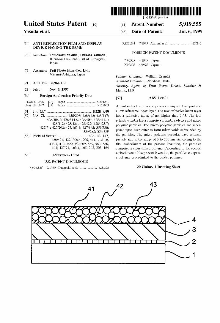
An anti-reflection film comprises a transparent Support and a low refractive index layer. The low refractive index layer has a refractive index of not higher than 1.45. The low refractive indeX layer comprises a binder polymer and micro polymer particles. The micro polymer particles are Super posed upon each other to form micro Voids Surrounded by the particles. The micro polymer particles have a mean particle size in the range of 5 to 200 nm. According to the first embodiment of the present invention, the particles comprise a cross-linked polymer. According to the Second embodiment of the present invention, the particles comprise a polymer cross-linked to the binder polymer.
20 Claims, 1 Drawing Sheet
42 43
24 Wa-C/NZ 6CC6 XOOOOOO2

U.S. Patent Jul. 6, 1999 5,919,555
Figure 43
7 YN247 Y-Z7 V424/YTYN/Yar/YZ/YaK7 NZ 8.32 3229 69C96 9COOCO559.5C2O5CCOOy
N
5,919,555 1
ANT-REFLECTION FILM AND DISPLAY DEVICE HAVING THE SAME
FIELD OF THE INVENTION
The present invention relates to an anti-reflection film Suitable for lowering reflection of light on a displaying Surface of a display device. The invention also relates to a display device provided with the anti-reflection film.
BACKGROUND OF THE INVENTION
As anti-reflection films for visible light, multi-layered films wherein plural transparent layers made of metal com pounds (e.g., metal oxides) are Superposed one on another have been employed. In the case that a monolayer film is employed instead of the multi-layered film, the monolayer film cannot effectively lower reflection of light having wide wavelength region (e.g., visible light), though the monolayer film can lower reflection of monochromatic light.
In the multi-layered film, increase of the number of the layers can enlarge a wavelength region of light to which the multi-layered film can apply. Therefore, the known anti reflection film is the multi-layered film composed of two or more metal oxide layers which are deposited by means of deposition. However, formation of the multi-layered film requires a complicated proceSS comprising a number of physical or chemical deposition procedures which corre spond to the number of the metal compound layerS having predetermined refractive indeX and thickness, under highly precise control of the thickness for each layer. Further, on the multi-layered film, a fluororesin layer is needed to be formed to improve Stain resistance (e.g., resistance to formation of fingerprint onto the Surface of the film).
Alternatively to the multi-layered film, it is known to use, as the anti-reflection film, a film in which refractive indices to air gradually vary in the thickness direction. Japanese Patent Provisional Publication No. 2(1990)-245702 describes an anti-reflection film comprising MgF2 micro particles and SiO, micro particles having refractive index between those of glass and MgF2, in which blending ratio of the MgF2 micro particles and SiO micro particles varies in the thickness direction. In more detail, the anti-reflection film is prepared by coating a liquid containing a mixture of the MgF2 micro particles and SiO micro particles on a glass plate So as to reduce a ratio of the SiO2 micro particles to MgF micro particles. Thus formed anti-reflection film shows a little variation of refractive indices between its bottom and the upper Surface of the glass plate. Therefore, the anti-reflection film shows a high anti-reflection effect.
Japanese Patent Provisional Publication No. 5(1993)- 13021 also describes an anti-reflection film comprising two layers of MgF2 micro particles and SiO micro particles dispersed in ethyl Silicate, a first layer containing MgF2 micro particles and SiO2 micro particles at ratio of 7/3 and a Second layer containing MgF2 micro particles and SiO2 micro particles at ratio of 1/1. The first layer has a refractive index of 1.42 and the Second layer has a refractive index of 1.44. Thus, the anti-reflection film does not show a satis factory anti-reflection effect.
Japanese Patent Provisional Publication No. 7(1995)- 92305 describes an anti-reflection film which comprises polymer particles (e.g., refractive index: 1.428) composed of a core and shell there around and which has a structure composed of an uneven Surface portion of a low refractive indeX comprising air and the polymer particles and a portion comprising only the polymer particles. The core is com posed of copolymer of methyl methacrylate, methacrylic
15
25
35
40
45
50
55
60
65
2 acid, trifluoroethyl acrylate and N-isobutoxymethyl acrylate, and the shell is composed of copolymer of Styrene, acrylic acid and butyl acrylate.
Japanese Patent Provisional Publication No. 7(1995)- 168006 describes an anti-reflection film which has a struc ture composed of an uneven Surface portion of a low refractive index comprising air and particles (e.g., MgF), a portion (intermediate refractive index) comprising only the particles thereunder, and a portion comprising the particles and binder.
Japanese Patent Provisional Publications No. 2(1990)- 245702, No. 5(1993)-13021, No. 7(1995)-92305 and No. 7(1995)-168006 mentioned above, all describe a film in which the refractive indices gradually vary in the thickneSS direction. However, the preparation of these films require complicated procedures and Skilled art, and further the films do not show a Satisfactory anti-reflection effect.
SUMMERY OF THE INVENTION
The problems of the known anti-reflection films can be Solved by forming micro Voids Surrounded by particles. An improved anti-reflection film comprises a transparent Sup port and a specific low refractive indeX layer. The low refractive indeX layer comprises a binder polymer and micro polymer particles. The micro polymer particles are Super posed upon each other to form micro Voids Surrounded by the particles. The improved anti-reflection film shows a high anti
reflection effect, which is obtained by the micro voids formed in the low refractive index layer. Further, the film can be prepared by a simple process. Furthermore, an image display device provided with the anti-reflection film can also be prepared by a simple process.
However, the applicants note a problem of the improved anti-reflection film. The micro voids formed in the low refractive indeX layer degrade the mechanical Strength of the layer. An object of the present invention is to improve the
mechanical Strength of the low refractive indeX layer con taining micro Voids. The present invention provides an anti-reflection film of
the first embodiment comprising a transparent Support and a low refractive indeX layer having a refractive index of not higher than 1.45, Said low refractive indeX layer comprising a binder polymer and micro polymer particles, Said micro polymer particles being Superposed upon each other to form micro Voids Surrounded by the particles, and Said micro polymer particles having a mean particle Size in the range of 5 to 200 nm, wherein the particles comprise a croSS-linked polymer. The invention also provides a display device having a
display surface covered with the anti-reflection film of the first embodiment defined above. The invention further provides an anti-reflection film of
the Second embodiment comprising a transparent Support and a low refractive indeX layer having a refractive index of not higher than 1.45, Said low refractive indeX layer com prising a binder polymer and micro polymer particles, Said micro polymer particles being Superposed upon each other to form micro Voids Surrounded by the particles, and Said micro polymer particles having a mean particle size in the range of 5 to 200 nm, wherein the particles comprise a polymer cross-linked to the binder polymer. The invention furthermore provides a display device
having a display Surface covered with the anti-reflection film of the second embodiment defined above.
5,919,555 3
According to the present invention, the mechanical Strength of the low refractive indeX layer is enhanced by a cross-link between polymers. The low refractive index layer contain two polymers, namely the polymer of the particles and the binder polymer. According to the first embodiment of the invention, the polymers of the particles are croSS linked to each other. According to the Second embodiment of the invention, the polymer of the particles are croSS-linked to the binder polymer.
BRIEF DESCRIPTION OF THE DRAWINGS
FIGURE is a cross-sectional view schematically showing a representative example of the anti-reflection film of the present invention.
DETAILED DESCRIPTION OF THE INVENTION
Layered Structure The anti-reflection film comprises a transparent Support
and a low refractive indeX layer having a refractive index of not higher than 1.45. The low refractive index layer com prises a binder polymer and micro polymer particles. The micro polymer particles are Superposed upon each other to form micro voids surrounded by the particles. The micro polymer particles have a mean particle size in the range of 5 to 200 nm.
A high refractive indeX layer having a refractive index of not lower than 1.6 is preferably provided between the transparent Support and the low refractive indeX layer. A hard coating layer is also preferably provided between the transparent Support and the low refractive indeX layer or the high refractive indeX layer.
Figure is a cross-sectional view Schematically showing a representative example of the anti-reflection film of the present invention. The anti-reflection film shown in the Figure comprises a transparent Support (1), a hard coating layer (2), a high refractive indeX layer (3) and a low refractive index layer (4) in the order. The low refractive indeX layer (4) comprises a binder polymer (41) and micro polymer particles (43). The micro polymer particles (43) are Superposed upon each other to form micro voids (42) surrounded by the particles (43).
The high refractive index layer and the low refractive index layer preferably satisfy the following formulas:
(High refractive index layer) mfa-wx0.7<nd <nf4Wx1.3
(Low refractive index layer) infaAx0.7<nd.<nf4Wx1.3
in which m represents a positive integer (generally 1, 2 or 3), in represents a refractive index of the high refractive indeX layer, d represents a thickness (nm) of the high refractive indeX layer, in represents a positive odd number (generally 1), n represents a refractive index of the low refractive indeX layer, and d represents a thickness (nm) of the low refractive index layer. The refractive index (n) of the high refractive index layer is higher by at least 0.05 than that of the transparent film, and the refractive index (n2) of the low refractive index layer is lower by at least 0.05 (preferably 0.1) than that of the high refractive index layer and lower by at least 0.05 than that of the transparent film. Further, n generally is not lower than 1.6, and is preferably in the range of 1.6 to 1.7.
15
25
35
40
45
50
55
60
65
4 The above-mentioned formulas are described in Japanese
Patent Provisional Publication No. 59(1984)-50401. Low Refractive Index Layer The low refractive indeX layer contains particles and a
binder polymer. The particles generally arranged in plane direction in the thickness of one particle to form one particle layer, and Several particle layers are Superposed to form the low-refractive layer. The micro voids formed by the Sur rounding particles are generally formed uniformly in Void Size and in interval because the sizes of the particles are almost the same one another. The air contained in the micro voids has a refractive index of 1.00, while the polymers of the low refractive indeX layer generally have a refractive index of 1.25 to 1.45. The low-refractive layer generally shows an intermediate value between a refractive index of air and that of the particles. Thus, the refractive index of the low refractive indeX layer can be lowered by increasing the Volume fraction of the micro Voids through using fine particles and forming micro Voids between the fine particles. The mean particle size of the particles generally is in the range of 5 to 200 nm, preferably 5 to 70 nm, and more preferably 5 to 50 nm. The low-refractive index layer has a thickness generally in the range of 50 to 400 nm, and preferably in the range of 50 to 200 nm. The present invention is characterized in that the poly
mers used in the low refractive indeX layer are crosslinked. The cross-link can be formed (a) between the polymers of a particle, (b) between the polymer of a particle and the binder polymer, (c) between the polymer of a particle and the polymer of another particle, or (d) between the binder polymers. The first embodiment relates to the cross-link of (a). The second embodiment relates to the cross-link of (b). The cross-link of (a) can be combined with the cross-link of (b). Further, the cross-link of (a) or (b) can be combined with the cross-link of (c) or (d). The cross-link of (a) is introduced into the polymers
before forming the low refractive index layer. The cross-link of (a) can be formed by polymerizing monomers having two or more polymerizable functional group. On the other hand, the cross-link of (b), (c) or (d) is introduced into the polymers after forming the low refractive index layer. The cross-link of (b), (c) or (d) can be formed by a reaction between the polymerS having a croSS-linkable functional group. The reaction can be conducted by using a polymer ization initiator (e.g., a photopolymerization initiator, a thermal polymerization initiator).
In the case that the particles have a core-shell Structure, the cross-link of (a) is introduced into the polymer of the core, and the cross-link of (b) or (c) is introduced into the polymer of the shell. According to the first embodiment of the present
invention, the particles comprise a croSS-linked polymer. At least 5 mole % of the repeating units of the polymer preferably have a branch to be cross-linked. The cross linked polymer of the particles can be formed by polymer ization of ethylenically unsaturated monomers. At least 5 mole % of the monomers have two or more ethylenically unsaturated bonds.
According to the Second embodiment of the present invention, the particles comprise a polymer croSS-linked to the binder polymer. The low refractive index layer of the Second embodiment can be formed by coating a photopo lymerization initiator, a binder polymer having a reactive group or monomers for the binder polymer and particles comprising a polymer having a reactive group, and irradi ating the coated layer with ultraViolet ray to form the covalent bond between the binder polymer and the polymer
5,919,555 S
of the particles. Each of the reactive groups of the binder polymer and the polymer of the particles preferably is an epoxy group or an ethylenically unsaturated bond.
In the case that at least 20 mole % (preferably 30 to 80 mole %, and more preferably 35 to 50 mole %) of the repeating units has a branch to be cross-linked, micro Voids are formed inside the particles in addition to the micro Voids Surrounded by the particles. Accordingly, the Volume of the micro Voids can be increased by increasing the repeating units having a branch to be cross-linked.
The micro void is preferably formed in an amount of 3 to 50 volume 7% of the low refractive index layer, and prefer ably 5 to 35 volume %.
Further, the polymer of the particles preferably contains fluorine atoms in an amount of 15 to 75 weight %, more preferably in an amount of 25 to 75 weight 9%, further preferably in an amount of 35 to 75 weight %, and most preferably 45 to 70 weight %.
The polymers containing fluorine atoms are formed by polymerizing monomers containing a fluorine atom. Examples of the monomers include fluoroolefins (e.g., fluoroethylene, vinylidene fluoride, tetrafluoroethylene, hexafluoropropylene, perfluoro-2,2-dimethyl-1,3-dioxonol), completely or partially fluorinated alkyl acrylates or meth acrylates and completely or partially fluorinated vinyl ethers. The fluorinated alkyl acrylates or methacrylates are preferred. Accordingly, the polymers containing fluorine atoms preferably comprises the following repeating units:
-CH-C-
COO- (CH2) -CF31. m
in which R" is hydrogen, methyl or a fluorine atom, and each of p and n independently is an integer.
The polymer of the particles may comprise repeating units containing no fluorine atom. The repeating unit is obtained by polymerizing a monomer containing no fluorine atom. Examples of the monomers include olefins (e.g., ethylene, propylene, isoprene, vinyl chloride, vinylidene chloride), acrylic esters (e.g., methyl acrylate, ethyl acrylate, 2-ethylhexyl acrylate), methacrylic esters (e.g., methyl methacrylate, ethyl methacrylate, butyl methacrylate), Styrene, Styrene derivatives (e.g., vinyl toluene, C.-methylstyrene), Vinyl ethers (e.g., methyl vinyl ether), vinyl esters (e.g., vinyl acetate, vinyl propionate), acryla mide S (e.g., N-tert-butyla crylamide, N-cyclohexylacrylamide), methacrylamides and acryloni triles.
The polymer of the particles used in the first embodiment of the invention further compriseS repeating units having a branch to be croSS-linked to each other. The repeating unit is formed by polymerizing a monomer having two or more ethylenically unsaturated groups. Examples of the mono mers include dienes (e.g., butadiene, pentadiene, divinylcyclohexane), diacrylic, triacrylic or polyacrylic esters (e.g., ethylene glycol diacrylate, 1,4-cyclohexane diacrylate, dipentaerythritol hexaacrylate), dimethacrylic, triacrylic or polyacrylic esters (e.g., ethylene glycol dimethacrylate, 1,2,4-cyclohexane trimethacrylate, pen taerythritol tetramethacrylate), Styrene derivatives (e.g., 1,4- divinylbenzene, 2-acryloylethyl 4-vinylbenzoate), bis acrylamides (e.g., methylene bis-acrylamide) and bis methacrylamides. The monomers may contain a fluorine atOm.
5
15
25
35
40
45
50
55
60
65
6 The polymer of the particles used in the second embodi
ment of the invention further comprises repeating units having a branch to be croSS-linked to a binder polymer. The repeating unit is formed by polymerizing a monomer having a cross-linkable reactive group (which remains after polymerization) and reacting the group with a reactive group of the binder polymer. Examples of the monomers include monomers having an epoxy group (e.g., glycidyl acrylate, glycidyl methacrylate) and a monomer having an ethyleni cally unsaturated bond (e.g., allyl methacrylate). The mono merS may contain a fluorine atom. The polymer particles can be prepared in the form of a
polymer lateX according to a conventional emulsion poly merization method, which comprises a Step of emulsifying the monomer, a polymerization initiator and a dispersing agent in a medium. The medium preferably is water or a mixture of water and an organic Solvent miscible with water. Examples of the organic Solvents include methanol, ethanol and acetone. The amount of the monomer is preferably in the range of 5 to 40 wt.% of the medium. The amount of the polymerization initiator is preferably in the range of 0.05 to 5 wt.% of the monomer. The amount of the dispersing agent is preferably in the range of 0.1 to 20 wt.%. The mixture is stirred at 30 to 100° C. (preferably 60 to 90° C) for 3 to 8 hours.
Examples of the polymerization initiators include inor ganic peroxides (e.g., potassium perSulfate, ammonium perSulfate), azonitriles (e.g., Sodium azobiscyanovalerate), aZoamidines (e.g., 2,2'-azobis(2-methylpropionamide hydrochloride), cyclic azoamidines (e.g., 2,2'-azobis2 (5methyl-2-imidazoline-2-yl)propanel hydrochloride) and aZoamides (e.g., 2,2'-azobis {2-methyl-N-1, 1'-bis (hydroxymethyl)-2-hydroxyethylpropionamide). Potas sium perSulfate and ammonium perSulfate are preferred. A Surface active agent (anionic, nonionic, cationic or
amphoteric) can be used as the dispersing agent. An anionic Surface active agent is preferably used as the dispersing agent. A core-shell particle can be prepared in the form of a
core-shell lateX according to a Seed emulsion polymerization method, which comprises Steps of forming a core monomer emulsion, polymerizing the core monomer to form an aque ous dispersion of core polymer particles, dropwise adding a shell monomer to the dispersion, and polymerizing the shell monomer. The core latex can be obtained by the above mentioned emulsion polymerization method. A commer cially available lateX can be used as the core lateX. At the Step of adding the shell monomer, it is not preferred
to further add a dispersing agent to the latex. An exceSS amount of the dispersing agent may form particles consist ing of the Shell polymer. The exceSS amount of the disperS ing agent is preferably removed from the reaction Solution by filtration.
The obtained particles can be stored in the form of powder. The powder can be obtained according to a con ventional drying method, Such as a freeze-drying method. The power can be obtained by a combination of agglom eration and filtration. The agglomeration can be caused by adding a strong acid or a Salt to the particle dispersion or by repeating freeze and thaw of the dispersion. Two or more kinds of particles can be used in combination
in the low refractive index layer. The glass transition temperature of the polymer of the
particles preferably is higher than the glass transition tem perature of the binder polymer. The difference between the glass transition temperatures preferably is not Smaller than 5 C., more preferably is not smaller than 20 C.

5,919,555 7
The binder polymer preferably compriseS repeating units having a branch to be cross-linked. The binder polymers are preferably cross-linked to each other or to the polymers of the particles. The repeating unit is formed by polymerizing a monomer having a cross-linkable reactive group (which remains after polymerization) and reacting the group with a reactive group of another binder polymer or a polymer of the particles. The reactive group preferably is an epoxy group or an ethylenically unsaturated bond (e.g., vinyl group). The binder polymer can be Synthesized from a monofunctional monomer, a polyfunctional monomer, a polyfunctional oli gomer or a polyfunctional polymer. The polyfunctional oligomer and the polyfunctional polymer can be used in the form of a latex. The polyfunctional oligomer is preferably used to Synthesize the binder polymer.
In the case that the particles are dispersed in water, a water-soluble polymer is preferably used as the binder. In the case that the particles are dispersed in an organic Solvent, a polymer Soluble in the organic Solvent is preferably used as the binder.
Examples of monomers or oligomers used to Synthesize the binder polymers are shown below.
(BP-1) CH
-(CH2-)s-
COCH(CF)2
CH
- (CH-C)s- O
CO2CH2CH -CH2
(aqueous dispersion, particle size: 20 nm, number average molecular weight: 72,000)
(BP-2) CH=CHCOO-CH CH, OCOCHFCH2
CH=CHCOO-CH -CCHOCH2C-CH-OCOCH=CH
CH=CHCOO-CH CH-OCOCH=CH
(BP-3)
(CH-City H. CH2 O
CHHOCH2CHCH
CH2
OCH2CH CH2 V/ O
(BP-4) CH=CH
15
25
35
40
45
50
55
60
8 -continued
CH
CHFC
COCH
CH3
CHFC
CH (CH2) 3) OCH2CH CH2
OCH2CHCH
CH=CH
COO-CH
CH-C-CH
COO-CH
CHFCH
--CH=CH
CH
CHFC
loo-ch, COO-CH
CHFC
CH
CHFCH
CHFCH COO CH2
COO-CH -C-CHOH
COO-CH
CHFCH
(BP-5)
(BP-6)
(BP-7)
(BP-8)
(BP-9)
(BP-10)
(BP-11)
(BP-12)

5,919,555
-continued
(BP-13) CHFCH
CHFCH COO CH2
COO-CH-C-CHCH
COO-CH
CHFCH
(BP-14) CHFCH
CHFCH COO-CH CHFCH
COO-CH -C-CH-OCO
COO-CH
CHFCH
(BP-15) CH CHCHOCH2CH2OCH2CH CH2
\\ Y/ (BP-16)
CH3
al-clicholactorict-l. Y.
(BP-17) O
/N CH-CHCHO-CH O
CH-CHCHO-CH -C-CH-OCHCHH-CH
CH, CHCHO-CH V/ O
(BP-18) CH CHCH-O-(CH2CHCHOCH2CHCHO)-CHCH-CH S/
OH och Civil O
(BP-19)
victor-()-cooleyn O O
(BP-20)
CH CH
-at-i- - (CH-C)s- COCH2CF CO2CH2CHFCH
2
(number average molecular weight: 60,000)
(BP-21) CH
-(CH2-)so - (CH-C) /V CO2CH2(CF2).H COCHCHH-CH
(number average molecular weight: 65,000)
15
25
35
40
45
50
55
60
65
-continued (BP-22)
CH
- (CH-C)so- -(CH-CH)- /V CO2(CH2)3CH3 CO2CH2CHCH
(number average molecular weight: 68,000)
Two or more binder polymers can be used in combination. The weight ratio of the polymer particles to the binder
polymer is preferably in the range of 30 to 95 wt.%, more preferably in the range of 50 to 90 wt.%.
According to the Second embodiment of the invention, a croSS-link is introduced between the polymer of the particle and the binder polymer. The cross-link is preferably formed by using a radical or cationic photopolymerization initiator. Examples of the radical photopolymerization initiators include carbonyl compounds (e.g., aromatic ketones, acetophenones, diketones), Sulfur compounds (e.g., disulfides), organic peroxides (e.g., benzoyl peroxides) and aZo compounds (e.g., azobisisobutyronitrile). Examples of the cationic polymerization initiators include onium Salts Such as diaryl iodonium Salts, triaryl Sulfonium Salts and aromatic diazonium Salts. Acetophenones and diaryl iodo nium Salts are preferred. The amount of the photopolymer ization initiator is preferably in the range of 0.1 to 10 wt.%, and more preferably in the range of 0.5 to 7 wt.% based on the solid contents (the particles and the binder) of the low refractive indeX layer.
In the case that a Small amount of binder is employed in the low refractive index layer, the binder is needed to be used So as not to fill up the micro voids. Preferred examples of binder include water-soluble resins such as polyvinyl alcohol and Polyoxyethylene, acrylic resins Such as polym ethyl acrylate and polymethyl acrylate; and cellulose deriva tives Such as nitrocellulose. Further, in the case that a polymerizable binder is employed as a binder for particles, the resultant layer of the particles can be croSS-linked by ultraViolet radiation or heating. The binder is generally employed in the minimum amount for enabling the bonding between the particles. The binder (e.g., Polyvinyl alcohol) is generally employed in the amount of less than 25 weight %, preferably less than 10 weight 9%. The low refractive index layer can be formed by coating
a coating Solution of the particles (e.g., latex) and a binder polymer (or monomers for the binder polymer) in a medium (e.g., Water, organic Solvent) on a transparent Support or a high refractive indeX layer, and drying the coated layer. The coating is generally conducted according to a conventional coating method Such as a dip coating method, an air knife coating method, a curtain coating method, a roller coating method, a wire bar coating method, a graver coating method or an extrusion coating method using a hopper (described in U.S. Pat. No. 2,681,294). Two or more layers (e.g., low and high refractive indeX layers) can be simultaneously coated on a transparent Support. The Simultaneous coating method is described in U.S. Pat. Nos. 2,761,791, 2,941,898, 3,508, 947 and 3,526,528. Transparent Support The transparent Support is generally made of a transparent
polymer (plastic) film. Examples of the polymers include cellulose derivatives (e.g., diacetyl cellulose, triacetyl cellulose, propionyl cellulose, butyryl cellulose and acetyl propionyl cellulose), polyamides, polycarbonates (described in U.S. Pat. No. 3,023,101), polyesters (described in Japa nese Patent Publication No. 48(1973)-40414, e.g., polyeth
5,919,555 11
ylene terephthalate, polyethylene naphthalate, polybutylene tere phthalate, poly-1,4-cyclohexane dimethylene terephthalate, polyethylene-1,2-diphenoxyethane-4,4'- dicarboxylate), poly Styrene, polyole fins (e.g., polypropylene, polyethylene and polymethylpentene), poly methyl methacrylate, Syndiotactic polystyrene, polysulfone, polyetherSulfone, polyarylate, polyether ketone, polyether imide and polyoxyethylene.
The transparent Support may have another function. For example, the Support can function as a protective film of a polarizing plate. High Refractive Index Layer Examples of materials for forming a high refractive indeX
layer having higher refractive indeX include organic mate rials Such as thermoplastic resins (e.g., polystyrene, copoly mers of Styrene and other monomer polymerizable with Styrene, polymer having an aromatic group, a heterocyclic group or a cycloalkyl or cycloalkenyl other than polystyrene, and polymers having a halogen atom other than fluorine atom), thermosetting resins (e.g., compositions con taining as a hardener melamine resin, phenol resin or epoxy resin, compositions for forming polyurethane (e.g., combi nation of heterocyclic or aromatic polyisocyanate and polyol), and radical curable compositions containing resin or prepolymer modified by introducing a group having double bond into the above polymer or resin. The materials pref erably have high film forming properties.
The high refractive indeX layer can be formed by using inorganic particles dispersed in an organic material. In this case, an organic material having a refractive indeX lower than the above materials can be employed because the inorganic particles generally have high refractive index. Naturally, the combination of inorganic particles and organic material enables the formation of layer having refractive indeX higher than that of layer of the above organic material. Any organic materials are employable in the combination So long as they have transparence and are capable of dispersing the inorganic particles. Examples of the organic materials include the above materials, vinyl resins, acrylic resins, polyesters, alkyd resins, cellulose derivatives, urethane resins, and Silicon compound Substituted with an organic group, and hardeners used together with these resins.
The Silicon compounds are generally compounds repre sented by the formula:
R'R''SiX ( ) in which each of R'' and R' independently represents an alkyl group, an alkenyl group, an aryl group or a hydrocar bon group Substituted with halogen, epoxy, amino, mercapto, methacryloyl or cyano; X represents one hydroly sis group Selected from the group consisting of an alkoxy group, an alkoxyalkoxy group, a halogen atom and an acyloxy group; each of a and b is 0, 1 or 2 provided a+b is 1 or 2; or hydrolysis products thereof.
Preferred examples of the inorganic compounds forming the inorganic particles include oxides of metals Such as aluminum, titanium, Zirconium and antimony. The inorganic compounds are available in the form of particle or dispersion in water and/or organic Solvent. The inorganic compound (particles) is dispersed in the above organic material and employed for forming the layer having higher refractive indeX. AS materials for forming the layer having higher refrac
tive index, further employable are the following inorganic materials which have film-forming properties and can be dispersed in Solvent or are per Se in liquid form. Examples of the inorganic materials include alkoxides of various
15
25
35
40
45
50
55
60
65
12 elements, Salts of organic acids, coordination compounds bonded to compound capable of forming coordination (e.g., chelate compounds), and activated inorganic polymers. Pre ferred examples of the inorganic materials include metal alkoxides Such as titanium tetraethoxide, titanium tetraiSopropoxide, titanium tetra-n-propoxide, titanium tetra-n-butoxide, titanium tetra-Sec-butoxide, titanium tetra tert-butoxide, aluminum trie thoxide, aluminum triisopropoxide, aluminum tributoxide, antimony triethoxide, antimony tributoxide, Zirconium tetraethoxide, Zirconium tetraiSopropoxide, Zirconium tetra-n-propoxide, Zirconium tetra-n-butoxide, Zirconium tetra-Sec-butoxide and Zirconium tetra-tert-butoxide; chelate compounds Such as diisoprop oxy titanium-bis(acetylace to nate), dibutoxytitanium-bis(acetylacetonate), diethoxytitanium-bis (acetylacetonate), bis(acetylacetone)Zirconium, aluminum acetylace to nate, aluminum di-n-but oxide monoethylacetylacetate, aluminum diisopropoxide monom ethylacetoacetate and tri-n-butoxide Zirconium monoethy lacetoacetate, and activated inorganic polymers comprising main component of Zirconyl carbonate ammonium or Zir conium. Further, various alkylsilicates or hydrolysis prod ucts thereof, and fine Silica particles (especially silica gel in colloidal state), although they have relatively low refractive index, can be employed in combination with the above inorganic materials. Other Treatments or Layers The anti-reflection film can be so treated as to have
anti-glare function (i.e., function Scattering an incident light on the Surface not to display a background view on the Surface). For example, an anti-reflection film can be pre pared by the Steps of forming unevenneSS on the Surface of the transparent Support and forming the low refractive index layer on the Surface. The formation of unevenneSS can be, for example, conducted by forming a layer containing inor ganic or organic particles on the Surface of the Support. Otherwise, particles having particle size of 50 nm to 2 nm larger than that of the particles of the low refractive index layer are incorporated into a coating liquid for forming the low refractive index layer in the amount of 0.1 to 50 weight % based on the amount of the particles of the low refractive indeX layer. Thus unevenneSS can be formed on the top Surface of the anti-reflection film. The anti-reflection film having the anti-glare function generally has a haze of 3 to 30%.
In the invention, an intermediate layer Such as a hard coating layer, a moisture proof layer or an antistatic layer can be provided on the Support. Examples of materials for forming the hard coating layer include polymer Such as acrylic resin, urethane resin or epoxy resin and/or oligomer and monomer (e.g., UV-curable resin); or material contain ing Silicon. Use of Anti-Reflection Film The anti-reflection film of the invention (preferably anti
reflection film having the anti-glare function) can be incor porated in a display device Such as a liquid crystal display (LCD), a plasma display (PDP), an electroluminescence display (ELD) or a cathode ray tube display (CRT). The transparent Support of the film (back Surface of the film) is attached to the display Surface. In the display device pro vided with the anti-reflection film of the invention, displayed image is easily observed. The liquid crystal display provided with the anti-reflection
film, for example, has the following structure: A liquid crystal display comprising a liquid crystal cell
which comprises a pair of Substrates provided with a trans parent electrode and nematic liquid crystal Sealed
5,919,555 13
therebetween, and a pair of polarizing sheets arranged on both sides of the cell; wherein at least one of the polarizing sheets is provided with the anti-reflection film thereon.
SYNTHESIS EXAMPLE 1. Synthesis of Polymer Particles (PP-1)
In a three neck flask of 200 ml having a cooling tube and a stirring device, a Solution of 2 g of Sodium dodecylben Zenesulfate in 90 ml of distilled water was placed. Further, a mixture of 17.8 g (70 mmol) of hexafluoroisopropyl methacrylate and 3.9 g (30 mmol) of divinylbenzene was added to the flask. The mixture was stirred at 200 rpm in a stream of nitrogen. After the flask was heated to 75 C., 2 ml of 8 wt.% aqueous Solution of Sodium perSulfate was added to the mixture. The polymerization reaction was conducted for 1 hour. Further, 2 ml of 8 wt.% aqueous solution of Sodium perSulfate was added to the mixture, and the reaction was conducted for 1.5 hour. The reaction mixture was cooled to the room temperature, and dialyzed through a cellulose membrane (fractional molecular weight: 10,000) to remove the exceSS Surface active agent and inorganic Salts from the Solution. The Solution was filtered off to remove insoluble matters. Thus 198g of white aqueous Solution was obtained. The solution was in the form of a latex having the Solid content of 8.9 wt.%. The average particle size of the latex was 114 nm. The lateX contain porous spherical particles including micro voids in an amount of about 27 volume 96. The particle size was measured according to a dynamic light Scattering method by using a particle size analyzer (N4, Coaltar). The shape of the particle was observed with a Scanning electron microScope. The Volume 76 of the Void was calculated from the refractive index (measured) of the particle and the refractive index (calculated) of the polymer.
SYNTHESIS EXAMPLE 2 Synthesis of Polymer Particles (PP-2)
In a three neck flask of 1 liter having a cooling tube and a stirring device, a Solution of 20 g of Sodium dodecylben Zenesulfate in 600 ml of distilled water was placed. Further, a mixture of 80 g (0.34 mol) of hexafluoroisopropyl methacrylate, 15 g (0.12 mol) of allyl methacrylate and 132 g (0.29 mol) of dipentaerythrytol hexaacrylate was added to the flask. The mixture was stirred at 200 rpm in a stream of nitrogen. After the flask was heated to 80° C., 10 ml of 8 wt. % aqueous Solution of Sodium perSulfate was added to the mixture. The polymerization reaction was conducted for 2 hours while adjusting pH in the range of 6.3 to 7.7 by using 3 wt.% aqueous solution of sodium hydroxide. The reaction mixture was cooled to the room temperature, and dialyzed through a cellulose membrane (fractional molecular weight: 10,000) to remove the excess Surface active agent and inorganic Salts from the Solution. The Solution was filtered off to remove insoluble matters. Thus 1,244 g of white aqueous Solution was obtained. The Solution was in the form of a latex having the solid content of 17.3 wt. %. The average particle size of the lateX was 154 nm. The lateX contain porous Spherical particles including micro Voids in an amount of about 34 volume %. The particle size was measured according to a dynamic light Scattering method by using a particle size analyzer (N4, Coaltar). The shape of the particle was observed with a Scanning electron microScope. The volume 76 of the void was calculated from the refractive index (measured) of the particle and the refractive index (calculated) of the polymer.
SYNTHESIS EXAMPLES 3 to 6 Synthesis of Polymer Particles (PP-3 to PP-6)
Polymer particles PP-3 to PP-6 shown below were syn thesized in the same manner as in the Synthesis Examples 1 and 2.
15
25
35
40
45
50
55
60
65
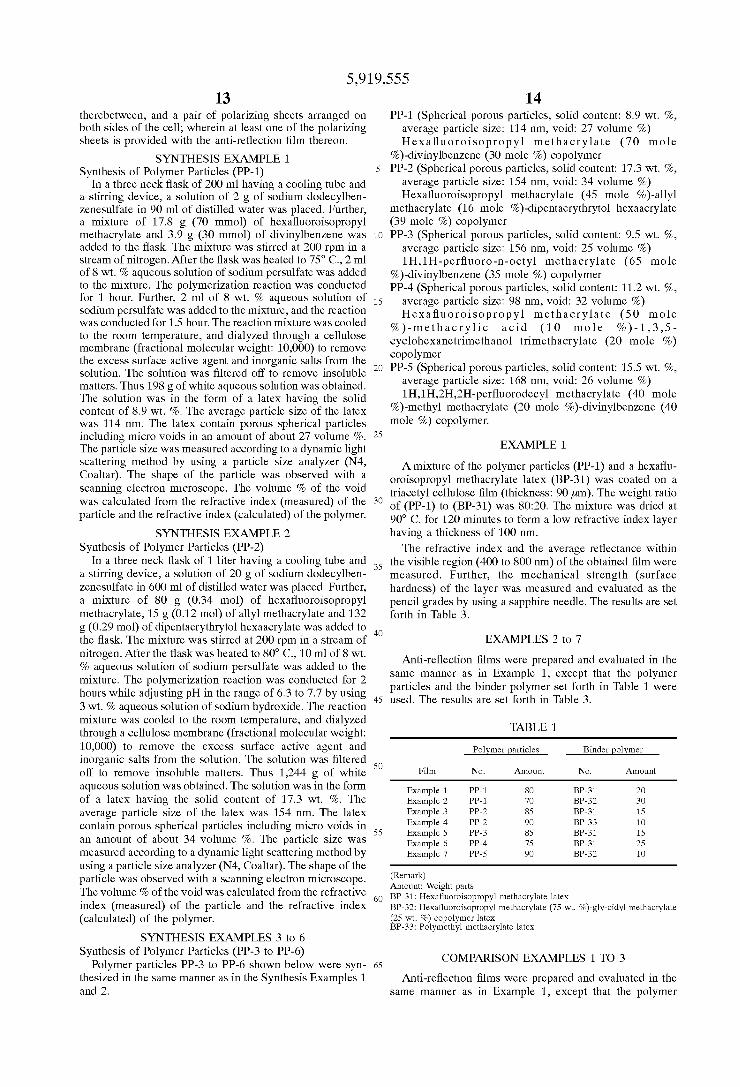
14 PP-1 (Spherical porous particles, solid content: 8.9 wt.%,
average particle size: 114 nm, void: 27 volume 96) Hexafluoro isopropyl methacrylate (70 mole
%)-divinylbenzene (30 mole %) copolymer PP-2 (Spherical porous particles, solid content: 17.3 wt.%,
average particle size: 154 nm, void: 34 volume 96) Hexafluoroisopropyl methacrylate (45 mole %)-allyl
methacrylate (16 mole %)-dipentaerythrytol hexaacrylate (39 mole %) copolymer PP-3 (Spherical porous particles, solid content: 9.5 wt.%,
average particle size: 156 nm, void: 25 volume 96) 1H, 1 H-perfluoro-n-octyl methacrylate (65 mole
%)-divinylbenzene (35 mole %) copolymer PP-4 (Spherical porous particles, solid content: 11.2 wt.%,
average particle size: 98 nm, void: 32 volume 96) Hexafluoro isopropyl methacrylate (50 mole
%)-methacrylic acid (10 mole %) -1,3,5- cyclohexanetrimethanol trimethacrylate (20 mole %) copolymer PP-5 (Spherical porous particles, solid content: 15.5 wt.%,
average particle size: 168 nm, void: 26 volume 96) 1H, 1H,2H,2H-perfluorodecyl methacrylate (40 mole
%)-methyl methacrylate (20 mole %)-divinylbenzene (40 mole %) copolymer.
EXAMPLE 1.
A mixture of the polymer particles (PP-1) and a hexaflu oroisopropyl methacrylate latex (BP-31) was coated on a triacetyl cellulose film (thickness: 90 um). The weight ratio of (PP-1) to (BP-31) was 80:20. The mixture was dried at 90° C. for 120 minutes to form a low refractive index layer having a thickness of 100 nm. The refractive indeX and the average reflectance within
the visible region (400 to 800 nm) of the obtained film were measured. Further, the mechanical Strength (Surface hardness) of the layer was measured and evaluated as the pencil grades by using a Sapphire needle. The results are Set forth in Table 3.
EXAMPLES 2 to 7
Anti-reflection films were prepared and evaluated in the Same manner as in Example 1, except that the polymer particles and the binder polymer set forth in Table 1 were used. The results are set forth in Table 3.
TABLE 1.
Polymer particles Binder polymer
Film No. Amount No. Amount
Example 1 PP-1 8O BP-31 2O Example 2 PP-1 70 BP-32 3O Example 3 PP-2 85 BP-31 15 Example 4 PP-2 90 BP-33 1O Example 5 PP-3 85 BP-31 15 Example 6 PP-4 75 BP-31 25 Example 7 PP-5 90 BP-32 1O
(Remark) Amount: Weight parts BP-31: Hexafluoroisopropyl methacrylate latex BP-32: Hexafluoroisopropyl methacrylate (75 wt.%)-gly-cidyl methacrylate (25 wt.%) copolymer latex BP-33: Polymethyl methacrylate latex
COMPARISON EXAMPLES 1. TO 3
Anti-reflection films were prepared and evaluated in the Same manner as in Example 1, except that the polymer

5,919,555 15
particles and the binder polymer set forth in Table 2 were used. The results are set forth in Table 3.
TABLE 2
Film Polymer particles Binder polymer
No. No. Amount No. Amount
Comp. 1 PP-51 8O BP-31 2O Comp. 2 PP-52 85 BP-32 15 Comp. 3 None BP-31 1OO
(Remark) PP-51: Methyl methacrylate (65 mole %)-divinylbenzene (35 mole %) copolymer latex PP-52: Methyl methacrylate (50 mole %)-butyl methacrylate (50 mole %) copolymer latex
TABLE 3
Anti-reflec- Refractive Surface Surface tion film index reflectance hardness
Example 1 1.32 O.4% 3H Example 2 1.32 O.4% 4H Example 3 1.33 O.5% 3H Example 4 1.32 O.4% 3H Example 5 1.32 O.3% 4H Example 6 1.32 O.4% 3H Example 7 1.33 O.6% 4H Comp. Ex. 1 1.42 4.0% 2H Comp. Ex. 2 148 4.5% B Comp. Ex. 3 1.34 O.8% 4B
EXAMPLE 8 (1) Formation of Hard Coating Layer (First Layer)
Atoluene Solution containing 5 wt.% of dipentaerythrytol hexaacrylate, 0.5 wt.% of a photopolymerization initiator (Irgacure 907, Ciba-Geigy) and 0.2 wt.% of a photosensi tizer (Kayacure DETX, Nippon Kayaku Co., Ltd.) was coated on a triacetyl cellulose film (thickness: 90 um) by using a wire bar to form a hard coating layer (thickness: 8 um). The coated layer was dried and heated to 100° C. An ultraViolet ray was irradiated to the layer by using a high pressure mercury lamp (12 W/cm) for 1 minute to harden the layer. The layer was cooled to the room temperature. (2) Formation of High Refractive Index Layer (Second Layer) With 100 g of an n-butyl methacrylate-methacrylic acid
copolymer latex HP-1 (copolymerization ratio: 80:20, aver age particle size: 63 nm, Solid content: 12.5 wt.%), 25g of tin oxide fine particles (Ishiwara Industries) were mixed. In 100 g of water, 6 g of dipentaerythrytol hexaacrylate, 0.5g of a photopolymerization initiator (Irgacure 907, Ciba Geigy), 0.2 g of a photosensitizer (Kayacure DETX, Nippon Kayaku Co., Ltd.) and 20 g of ethyl acetate were mixed and emulsified by using 1 g of Sodium dodecylbenzeneSulfonate. The obtained emulsion was added to the mixture, and the resulting mixture was stirred to form a coating Solution.
The coating Solution was coated on the hard coating layer by using a wire bar to form a high refractive indeX layer (thickness: 0.16 um). The coated layer was dried and heated to 100° C. An ultraviolet ray was irradiated to the layer by using a high pressure mercury lamp (12 W/cm) for 1 minute to harden the layer. The layer was cooled to the room temperature. (3) Formation of Low Refractive Index Layer (Third Layer)
In 100 g of water, 6 g of dipentaerythrytol hexaacrylate, 0.5 g of a photopolymerization initiator (Irgacure 907, Ciba-Geigy), 0.2 g of a photosensitizer (Kayacure DETX,
15
25
35
40
45
50
55
60
65
16 Nippon Kayaku Co., Ltd.) and 20 g of ethyl acetate were mixed and emulsified by using 1 g of Sodium dodecylben Zenesulfonate. The obtained emulsion was added to 87 g of the latex PP-1, and the resulting mixture was stirred to form a coating Solution. The coating Solution was coated on the high refractive
indeX layer by using a wire bar to form a high refractive index layer (thickness: 0.10 um). The coated layer was dried and heated to 100° C. An ultraviolet ray was irradiated to the layer by using a high pressure mercury lamp (12 W/cm) for 1 minute to harden the layer. The layer was cooled to the room temperature. The average reflectance within the visible region (400 to
800 nm) of the obtained film was measured. Further, the mechanical strength (Surface hardness) of the layer was measured and evaluated as the pencil grades. The results are set forth in Table 4.
EXAMPLES 9 TO 12
Anti-reflection films were prepared and evaluated in the Same manner as in Example 8, except that the polymer particles for the low refractive indeX layer and the polymer for the high refractive index layer set forth in Table 4 were used. The results are set forth in Table 4.
COMPARISON EXAMPLES 4 TO 5
Anti-reflection films were prepared and evaluated in the Same manner as in Example 8, except that the polymer particles for the low refractive index layer set forth in Table 4 were used. The results are set forth in Table 4.
TABLE 4
Anti-re- Polymer of Particles Surface flection second of third e- Surface film layer layer flectance hardness
Example 8 HP-1 PP-1 O.4% 4H Example 9 HP-1 PP-2 O.3% 4H Example 10 HP-2 PP-2 O.3% 3H Example 11 HP-3 PP-3 O.2% 4H Example 12 HP-4 PP-4 O.4% 3H Comp. 4 HP-1 PP-51 3.9% 2H Comp. 5 HP-1 PP-52 3.7% 2H
(Remark) HP-1: n-Butyl methacrylate (80 wt.%)-methacrylic acid (20 wt.%) copoly le
HP-2: Methyl methacrylate (65 wt.%)-ethyl methacrylate (25 wt.%)-acrylic acid (10 wt.%) copolymer HP-3: Benzyl methacrylate (50 wt.%)-methyl methacrylate (25 wt.%)-allyl methacrylate (20 wt.%)-methacrylic acid (5 wt.%) copolymer HP-4: Methyl methacrylate (35 wt.%)-styrene (20 wt.%)-2-f-naphthylethyl methacrylate (15 wt.%)-allyl methacrylate (10 wt.%)-acrylic acid (10 wt.%) copolymer
SYNTHESIS EXAMPLE 7 Synthesis of Polymer Particles (PP-11)
In a three neck flask of 5 liters having a cooling tube and a stirring device, a Solution of 30 g of Sodium dodecylben Zenesulfate in 2.7 liters of distilled water was placed. Further, a mixture of 480 g of hexafluoroisopropyl methacrylate, 60 g of divinylbenzene and 60 g of glycidyl methacrylate was added to the flask. The mixture was stirred at 200 rpm in a stream of nitrogen. After the flask was heated to 75 C., a solution of 12 g sodium persulfate in 150 ml of water was added to the mixture. The polymerization reaction was conducted for 5 hours. The reaction mixture was cooled to the room temperature, and dialyzed through a cellulose membrane (fractional molecular weight: 10,000) to remove the exceSS Surface active agent and inorganic Salts from the

5,919,555 17
Solution. The Solution was filtered off to remove insoluble matters. Thus 4,500 g of milky white acqueous solution was obtained. The solution was in the form of a latex having the solid content of 13.3 wt.%. The average particle size of the lateX was 30 nm. The particle size was measured according to a dynamic light Scattering method by using a particle size analyzer (N4, Coaltar).
SYNTHESIS EXAMPLE 8 Synthesis of Core Particles
In a three neck flask of 5 liters having a cooling tube and a stirring device, a Solution of 30 g of Sodium dodecylben Zenesulfate in 2.7 liters of distilled water was placed. Further, a mixture of 480 g of hexafluoroisopropyl meth acrylate and 120 g of divinylbenzene was added to the flask. The mixture was stirred at 200 rpm in a stream of nitrogen. After the flask was heated to 75 C., a solution of 12 g Sodium persulfate in 150 ml of water was added to the mixture. The polymerization reaction was conducted for 5 hours. The reaction mixture was cooled to the room temperature, and dialyzed through a cellulose membrane (fractional molecular weight: 10,000) to remove the excess Surface active agent and inorganic Salts from the Solution. The Solution was filtered off to remove insoluble matters. Thus 4,510 g of milky white aqueous solution was obtained.
15
18 The solution was in the form of a latex having the solid content of 13.2 wt.%. The average particle size of the latex was 20 nm.
Synthesis of Polymer Particles (PP-18) In a three neck flask of 100 ml having a cooling tube and
a stirring device, 75.7g of the core latex (solid content: 13.2 wt.%, solid amount: 10 g) and a solution of 0.022 g of Sodium dodecylbenzenesulfate in 10 ml of distilled water were placed. Further, a mixture of 0.55g of n-butyl meth acrylate and 0.55 g of glycidyl methacrylate was added to the flask. The mixture was stirred at 200 rpm in a stream of nitrogen. The polymerization reaction was conducted at 75 C. for 4 hours. The reaction mixture was cooled to the room temperature, and filtered off to remove insoluble matters. Thus 90.3 g of white aqueous dispersion was obtained. The dispersion was in the form of a lateX having the Solid content of 11.6 wt.%. The average particle size of the latex was 25
.
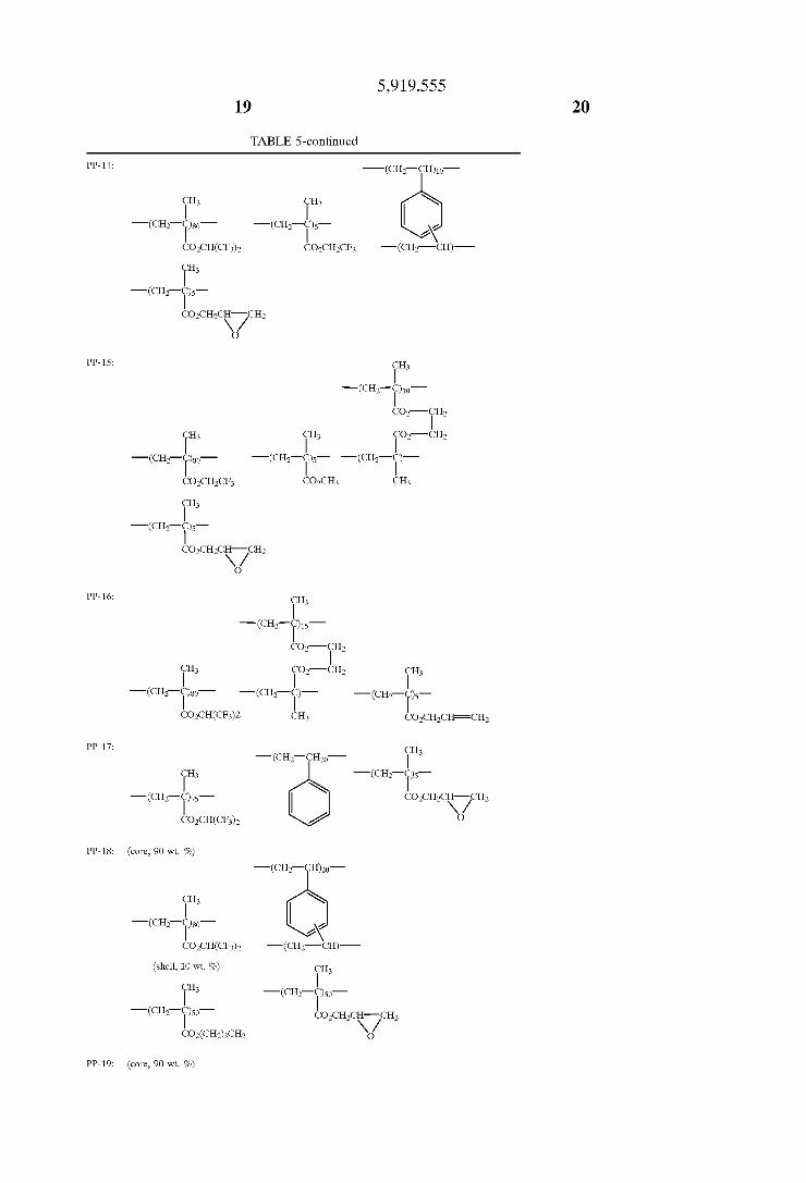
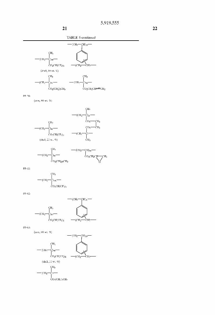
SYNTHESIS EXAMPLES 9 TO 19
Polymer particles PP-12 to PP-17, PP-19, PP-20, PP-61, PP-62, PP-63 shown in Table 5 were synthesized in the same manner as in the Synthesis Examples 7 and 8.
TABLE 5
Synthesis Polymer Average Content of Example Particles particle size fluorine atom
7 PP-11 30 mm 38.6 wt.% 9 PP-12 25 nm. 38.6 wt.% 10 PP-13 30 mm 38.6 wt % 11 PP-14 45 nm. 40.3 wt.% 12 PP-15 22 mm 38.6 wt.% 13 PP-16 35 mm 38.6 wt.% 14 PP-17 32 nm. 36.2 wt.% 8 PP-18 25 nm. 34.8 wt.%
15 PP-19 24 nm. 34.8 wt.% 16 PP-20 28 nm. 35.7 wt.% 17 PP-61 18 mm 48.3 wt.% 18 PP-62 20 mm 38.6 wt.% 19 PP-63 25 nm. 34.8 wt.%
(Remark) PP-11: -(CH-CH)10
CH CH N
-(CH-C)o -(CH2-)so- 2X?
CO2CH2CH-CH2 CO2CH(CF3)2 -(CH-CH)-
PP-12: -(CH-CH)10
CH CH N
-(CH-C) -(CH2-)so- 2\?
COCH2CHFCH COCH(CFs) -(CH-CH)-
PP-13: CH -(CH-CH) 3
CH3 -(CH-C)0-
-(CH-C)so COCHCH-CH
5,919,555 23
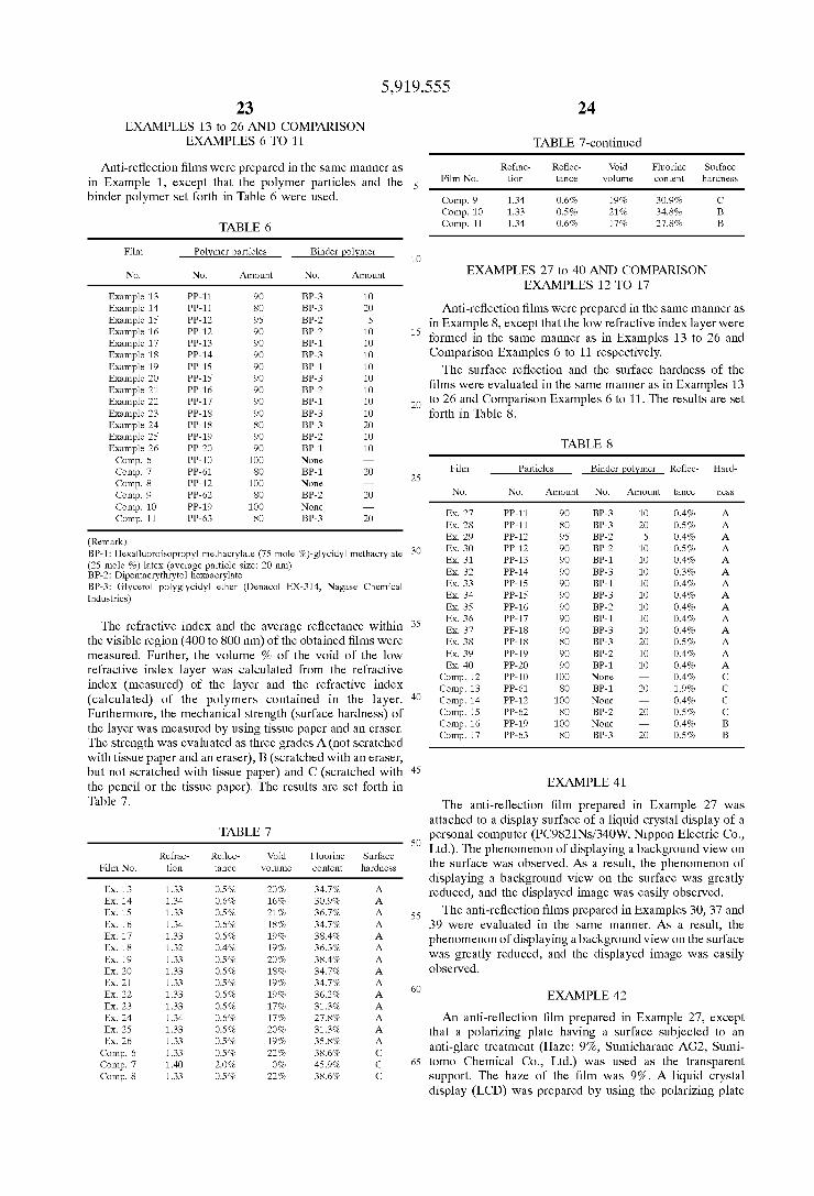
EXAMPLES 13 to 26 AND COMPARISON EXAMPLES 6 TO 11
Anti-reflection films were prepared in the same manner as in Example 1, except that the polymer particles and the binder polymer set forth in Table 6 were used.
TABLE 6
Film Polymer particles Binder polymer
No. No. Amount No. Amount
Example 13 PP-11 90 BP-3 1O Example 14 PP-11 8O BP-3 2O Example 15 PP-12 95 BP-2 5 Example 16 PP-12 90 BP-2 1O Example 17 PP-13 90 BP-1 1O Example 18 PP-14 90 BP-3 1O Example 19 PP-15 90 BP-1 1O Example 20 PP-15 90 BP-3 1O Example 21 PP-16 90 BP-2 1O Example 22 PP-17 90 BP-1 1O Example 23 PP-18 90 BP-3 1O Example 24 PP-18 8O BP-3 2O Example 25 PP-19 90 BP-2 1O Example 26 PP-20 90 BP-1 1O Comp. 6 PP-10 1OO None Comp. 7 PP-61 8O BP-1 2O Comp. 8 PP-12 1OO None Comp. 9 PP-62 8O BP-2 2O Comp. 10 PP-19 1OO None Comp. 11 PP-63 8O BP-3 2O
(Remark) BP-1: Hexafluoroisopropyl methacrylate (75 mole %)-glycidyl methacrylate (25 mole %) latex (average particle size: 20 nm) BP-2: Dipentaerythrytol hexaacrylate BP-3: Glycerol polyglycidyl ether (Denacol EX-314, Nagase Chemical Industries)
The refractive indeX and the average reflectance within the visible region (400 to 800 nm) of the obtained films were measured. Further, the volume 76 of the void of the low refractive indeX layer was calculated from the refractive index (measured) of the layer and the refractive index (calculated) of the polymers contained in the layer. Furthermore, the mechanical Strength (Surface hardness) of the layer was measured by using tissue paper and an eraser. The strength was evaluated as three grades A (not Scratched with tissue paper and an eraser), B (Scratched with an eraser, but not Scratched with tissue paper) and C (Scratched with the pencil or the tissue paper). The results are set forth in Table 7.
TABLE 7
Refrac- Reflec- Void Fluorine Surface Film No. ion tance volume content hardness
Ex. 13 33 0.5% 20% 34.7% A. Ex. 14 34 O.6% 16% 30.9% A. Ex. 15 33 0.5% 21% 36.7% A. Ex. 16 34 O.6% 18% 34.7% A. Ex. 17 33 0.5% 19% 38.4% A. Ex. 18 32 O.4% 19% 36.3% A. Ex. 19 33 0.5% 20% 38.4% A. Ex. 20 33 0.5% 18% 34.7% A. Ex. 21 33 0.5% 19% 34.7% A. Ex. 22 33 0.5% 19% 36.2% A. Ex. 23 33 0.5% 17% 31.3% A. Ex. 24 34 O.6% 17% 27.8% A. Ex. 25 33 0.5% 20% 31.3% A. Ex. 26 33 0.5% 19% 35.8% A. Comp. 6 33 0.5% 22% 38.6% C Comp. 7 .40 2.0% O% 45.9% C Comp. 8 33 0.5% 22% 38.6% C
1O
15
25
35
40
45
50
55
60
65
TABLE 7-continued
Refrac- Reflec- Void Fluorine Surface Film No. tion tance volume content hardness
Comp. 9 1.34 O.6% 19% 30.9% C Comp. 10 1.33 0.5% 21% 34.8% B Comp. 11 1.34 O.6% 17% 27.8% B
EXAMPLES 27 to 40 AND COMPARISON EXAMPLES 12 TO 17
Anti-reflection films were prepared in the same manner as in Example 8, except that the low refractive indeX layer were formed in the same manner as in Examples 13 to 26 and Comparison Examples 6 to 11 respectively. The Surface reflection and the Surface hardness of the
films were evaluated in the same manner as in Examples 13 to 26 and Comparison Examples 6 to 11. The results are set forth in Table 8.
TABLE 8
Film Particles Binder polymer Reflec- Hard
No. No. Amount No. Amount tance CSS
Ex. 27 PP-11 90 BP-3 1O O.4% A. Ex. 28 PP-11 8O BP-3 2O O.5% A. Ex. 29 PP-12 95 BP-2 5 O.4% A. Ex. 30 PP-12 90 BP-2 1O O.5% A. Ex. 31 PP-13 90 BP-1 1O O.4% A. Ex. 32 PP-14 90 BP-3 1O O.3% A. Ex. 33 PP-15 90 BP-1 1O O.4% A. Ex. 34 PP-15 90 BP-3 10 O.4% A. Ex. 35 PP-16 90 BP-2 1O O.4% A. Ex. 36 PP-17 90 BP-1 1O O.4% A. Ex. 37 PF-18 90 BP-3 1O O.4% A. Ex. 38 PP-18 8O BP-3 2O O.5% A. Ex. 39 PP-19 90 BP-2 1O O.4% A. Ex. 40 PP-20 90 BP-1 1O O.4% A.
Comp. 12 PP-10 1OO None O.4% C Comp. 13 PP-61 8O BP-1 2O 1.9% C Comp. 14 PP-12 1OO None O.4% C Comp. 15 PP-62 8O BP-2 2O O.5% C Comp. 16 PP-19 1OO None O.4% B Comp. 17 PP-63 8O BP-3 2O O.5% B
EXAMPLE 41
The anti-reflection film prepared in Example 27 was attached to a display Surface of a liquid crystal display of a personal computer (PC9821Ns/340W, Nippon Electric Co., Ltd.). The phenomenon of displaying a background view on the Surface was observed. As a result, the phenomenon of displaying a background View on the Surface was greatly reduced, and the displayed image was easily observed. The anti-reflection films prepared in Examples 30, 37 and
39 were evaluated in the same manner. As a result, the phenomenon of displaying a background view on the Surface was greatly reduced, and the displayed image was easily observed.
EXAMPLE 42
An anti-reflection film prepared in Example 27, except that a polarizing plate having a Surface Subjected to an anti-glare treatment (Haze: 9%, Sumicharane AG2, Sumi tomo Chemical Co., Ltd.) was used as the transparent support. The haze of the film was 9%. A liquid crystal display (LCD) was prepared by using the polarizing plate

5,919,555 25
having the anti-reflection film. As a result, the phenomenon of displaying a background View on the Surface was greatly reduced, and the displayed image was easily observed. We claim: 1. An anti-reflection film comprising a transparent Support
and a low refractive indeX layer having a refractive index of not higher than 1.45, Said low refractive indeX layer com prising a binder polymer and micro polymer particles, Said micro polymer particles being Superposed upon each other to form micro Voids Surrounded by the particles, and Said micro polymer particles having a mean particle size in the range of 5 to 200 nm, wherein the particles comprise a croSS-linked polymer.
2. The anti-reflection film as defined in claim 1, wherein the polymer particle is formed by polymerization of ethyl enically unsaturated monomers, at least 5 mole % of Said monomers having two or more ethylenically unsaturated bonds.
3. The anti-reflection film as defined in claim 2, wherein at least 20 mole % of Said monomers have two or more ethylenically unsaturated bonds, whereby micro Voids are formed inside the particles in addition to the micro Voids Surrounded by the particles.
4. The anti-reflection film as defined in claim 1, wherein the polymer of the particles contains fluorine atoms in an amount of 15 to 75 weight %.
5. The anti-reflection film as defined in claim 1, wherein the micro void is formed in an amount of 3 to 50 volume 76 of the low refractive index layer.
6. The anti-reflection film as defined in claim 1, wherein the polymer of the particles is further croSS-linked to the polymer of other particles.
7. The anti-reflection film as defined in claim 1, wherein the binder polymer and the polymer of the particles have glass transition temperatures, in which the glass transition temperature of the polymer of the particles is higher than the glass transition temperature of the binder polymer, and the difference between the glass transition temperatures is not Smaller than 5 C.
8. The anti-reflection film as defined in claim 1, wherein the binder polymer is cross-linked.
9. The anti-reflection film as defined in claim 1, wherein a high refractive indeX layer having a refractive index of not lower than 1.6 is provided between the transparent Support and the low refractive index layer.
10. A display device having a display Surface covered with an anti-reflection film defined in claim 1.
15
25
35
40
45
26 11. An anti-reflection film comprising a transparent Sup
port and a low refractive indeX layer having a refractive index of not higher than 1.45, said low refractive index layer comprising a binder polymer and micro polymer particles, Said micro polymer particles being Superposed upon each other to form micro Voids Surrounded by the particles, and Said micro polymer particles having a mean particle size in the range of 5 to 200 nm, wherein the particles comprise a polymer cross-linked to the binder polymer.
12. The anti-reflection film as defined in claim 11, wherein the low refractive indeX layer is formed by coating a photopolymerization initiator, a binder polymer having a reactive group or monomers for the binder polymer and particles comprising a polymer having a reactive group, and irradiating the coated layer with ultraViolet ray to form the covalent bond between the binder polymer and the polymer of the particles.
13. The anti-reflection film as defined in claim 12, wherein each of the reactive groups of the binder polymer and the polymer of the particles is an epoxy group or an ethylenically unsaturated bond.
14. The anti-reflection film as defined in claim 11, wherein the polymer of the particles contains fluorine atoms in an amount of 15 to 75 weight %.
15. The anti-reflection film as defined in claim 11, wherein the micro void is formed in an amount of 3 to 50 volume 76 of the low refractive index layer.
16. The anti-reflection film as defined in claim 11, wherein the particles have a core-shell Structure, Said core comprises a croSS-linked polymer, and Said shell comprises a polymer croSS-lined to the binder polymer.
17. The anti-reflection film as defined in claim 11, wherein the binder polymer and the polymer of the particles have glass transition temperatures, the glass transition tempera ture of the polymer of the particles is higher than the glass transition temperature of the binder polymer, and the dif ference between the glass transition temperatures is not Smaller than 5 C.
18. The anti-reflection film as defined in claim 11, wherein the binder polymer is cross-linked.
19. The anti-reflection film as defined in claim 11, wherein a high refractive indeX layer having a refractive index of not lower than 1.6 is provided between the transparent Support and the low refractive index layer.
20. A display device having a display Surface covered with an anti-reflection film defined in claim 11.
k k k k k