device configuration - basic settings
TRANSCRIPT

2018-12-13
ManualDevice configuration - basic settings
Device configuration - basic settings | 13.12.2018
page I
Table of Contents
1 GRIDVIS 7.3 ..................................................................................................2
2 NOMINAL VALUES ...........................................................................................6
3 RECORDING A CONFIGURATION .......................................................................9
4 SERIAL INTERFACE .......................................................................................16
5 TRANSFERRING THE CONFIGURATION ............................................................19
6 SAVING A CONFIGURATION FILE .....................................................................22
7 LOAD CONFIGURATION FILE...........................................................................24
8 GRIDVIS 7.3 ................................................................................................26

Device configuration - basic settings | 13.12.2018
page 1 of 27
These instructions explain how to configure the basic settings of a Janitza meter using GridVis software.Content
▪ Configuring the device identity ▪ Configuring transformer ratios ▪ Selecting measuring variants ▪ Configuring nominal values ▪ Configuring recordings ▪ Configuring serial interfaces ▪ Transferring the configuration ▪ Exporting/importing a configuration

Device configuration - basic settings | 13.12.2018
page 2 of 27
1 GridVis 7.3
Double-click the corresponding tree entry for the device to be configured.
Click the Configuration button.
Device configuration - basic settings | 13.12.2018
page 3 of 27
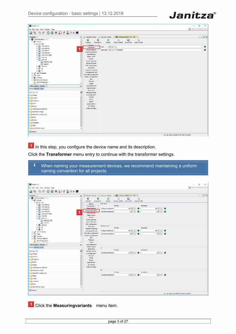
In this step, you configure the device name and its description.Click the Transformer menu entry to continue with the transformer settings.
When naming your measurement devices, we recommend maintaining a uniform naming convention for all projects.
Click the Measuringvariants menu item.

Device configuration - basic settings | 13.12.2018
page 4 of 27
On some devices, the measuring inputs 1-3 are called the main input and input 4 is called the secondary or auxiliary input. If you are using the measurement device to measure residual current, also configure the ratio of the residual current transformers here. (Here L5 and L6)
Click the dropdown button.
Select the appropriate measurement variant from the list.

Device configuration - basic settings | 13.12.2018
page 5 of 27
If you have connected the auxiliary measurement, also configure the connection diagram for this measurement here.
Click the Nominalvalues menu item.
Device configuration - basic settings | 13.12.2018
page 6 of 27
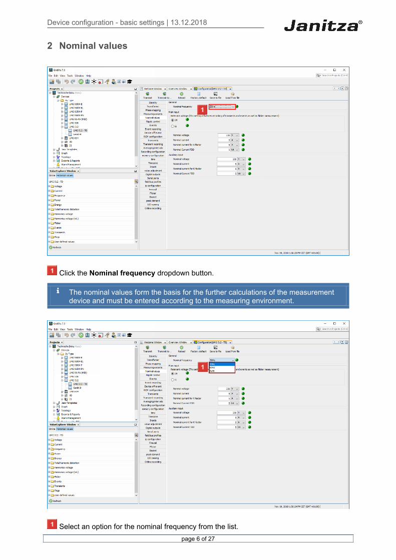
2 Nominal values
Click the Nominal frequency dropdown button.
The nominal values form the basis for the further calculations of the measurement device and must be entered according to the measuring environment.
Select an option for the nominal frequency from the list.

Device configuration - basic settings | 13.12.2018
page 7 of 27
You can either enter a fixed grid frequency or have the measurement device determine it automatically.
Use the selection field to select whether the LN or LL voltage is to be measured.
We recommend using the "LN" setting for measuring the power quality in low-voltage grids. “LL" should be used in medium-voltage power grids.
Click the Nennspannung input field.
Click the Nennstrom input field.
Click the Nennstrom für K-Faktor input field.The K-factor describes the increase in eddy current losses when loaded with harmonics. With a sinusoidal load on the transformer, the K factor = 1. The larger the K-factor is, the stronger a transformer can be loaded with harmonics without overheating.
Click the Nennstrom TDD input field.TDD (Total Demand Distortion) indicates the ratio between the current harmonics (THDi) and the effective current value at full load.

Device configuration - basic settings | 13.12.2018
page 8 of 27
Click the Recording configuration menu item.

Device configuration - basic settings | 13.12.2018
page 9 of 27
3 Recording a configuration
In order to automatically load recording profiles from a corresponding preset recording, click the corresponding button in the Preset recordings area.
You can choose from various presets to automatically create recording profiles that you can use to record the relevant standards.
Click the Yes button.

Device configuration - basic settings | 13.12.2018
page 10 of 27
Click the Edit button to edit the marked recording profile.

Device configuration - basic settings | 13.12.2018
page 11 of 27
To add more values to the recording profile, click the Add Values button.

Device configuration - basic settings | 13.12.2018
page 12 of 27
Select the desired value in the tree structure and drag it into the value window while holding down the left mouse button.

Device configuration - basic settings | 13.12.2018
page 13 of 27
After you have dragged all the desired values into the values window, click the OK button.
Click the radiobutton.The measured values can be recorded (depending on the device) in different ways (mode): ▪ Mean value (arithmetic/effective value)▪ Sample (for flow meters, gas, water, etc.)▪ For value changes (recording option for digital inputs)For the mean value, you can also record minimum and maximum values. Note the increased memory requirement here.
Click Min/Max.
Click the Timebase dropdown button.
The time base is only relevant for recording the mean, minimum, maximum values and sample.
A permanent recording of measured values with a time base <10 seconds can quickly exhaust the memory capacity.

Device configuration - basic settings | 13.12.2018
page 14 of 27
After you have configured the mode and time base for all values, click the OK button.

Device configuration - basic settings | 13.12.2018
page 15 of 27
Click the Serial ports menu item.

Device configuration - basic settings | 13.12.2018
page 16 of 27
4 Serial interface
Click the Device ID input field to configure the Modbus address of the device.
The device ID must be unique within a bus segment.
For devices that communicate as Modbus masters in the system, the ID 250 is often assigned in practice.

Device configuration - basic settings | 13.12.2018
page 17 of 27
Click the Mode dropdown button.
Select the desired mode from the list.
Depending on the model, the device can communicate via the bus in different ways.
Device configuration - basic settings | 13.12.2018
page 18 of 27
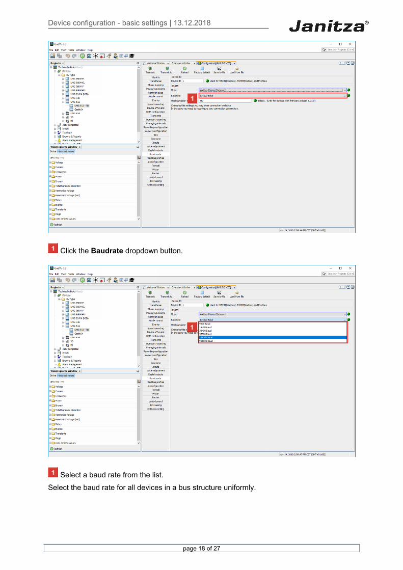
Click the Baudrate dropdown button.
Select a baud rate from the list. Select the baud rate for all devices in a bus structure uniformly.
Device configuration - basic settings | 13.12.2018
page 19 of 27
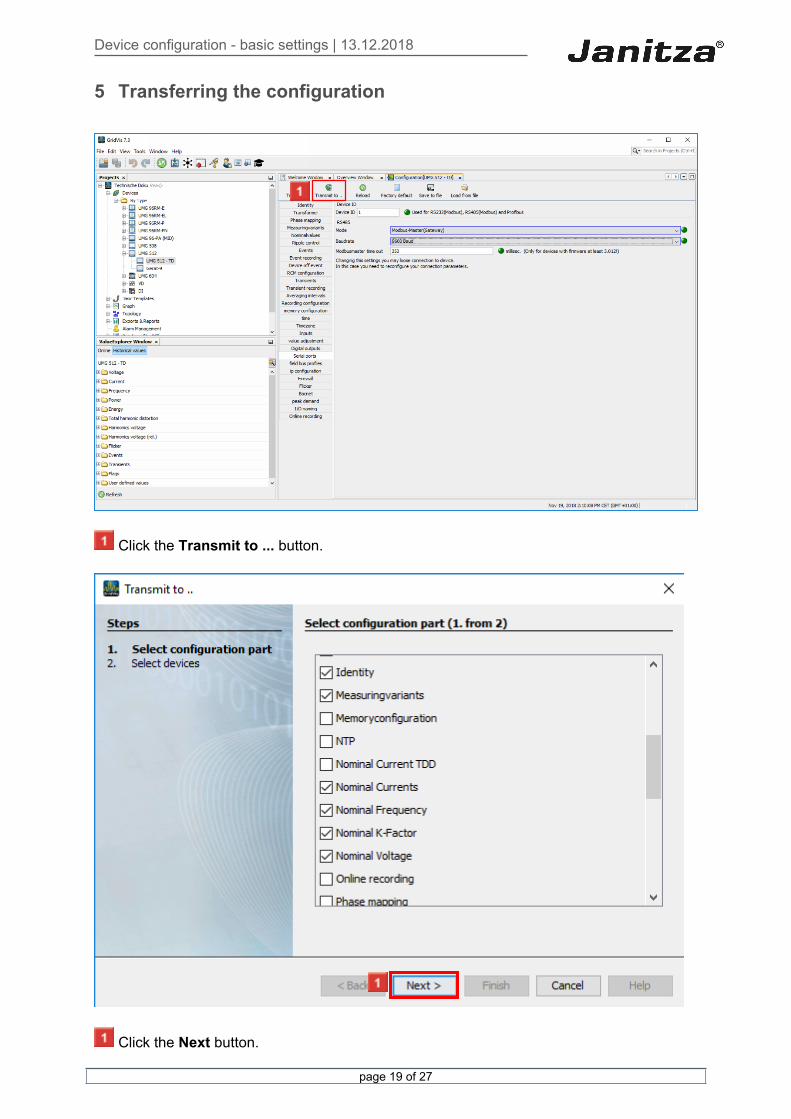
5 Transferring the configuration
Click the Transmit to ... button.
Click the Next button.

Device configuration - basic settings | 13.12.2018
page 20 of 27
Use the checkboxes to select which part of the configuration is to be transferred.
Select the desired device from the list.
Here, you can select several devices of the same type to simultaneously transfer the configuration to several devices.
Click the Finish button.

Device configuration - basic settings | 13.12.2018
page 21 of 27
Click the OK button.

Device configuration - basic settings | 13.12.2018
page 22 of 27
6 Saving a configuration file
Click the Save to file button to export the configuration.
Click the Save button.

Device configuration - basic settings | 13.12.2018
page 23 of 27
Click the OK button.

Device configuration - basic settings | 13.12.2018
page 24 of 27
7 Load configuration file
Click the Load from file button to load the configuration from a configuration file.
Select a valid GridVis configuration file.

Device configuration - basic settings | 13.12.2018
page 25 of 27
Click the Open button.
Click the OK button.

Device configuration - basic settings | 13.12.2018
page 26 of 27
8 GridVis 7.3
Please enter your text here.Identity The identity consists of the device name and a description.If several measurement devices are used, we recommend establishing a uniform designation.Transformer The voltage and current transformer ratio can be found in the transformer used or in the corresponding documentation.In some devices, the configuration of L1-L3 is combined as the main measurement. Serial interface Under this item, you configure the modbus communication settings. The same baud rate must be selected for devices in a bus.Transferring the configuration You can transfer the entire configuration to the measurement device by clicking Transmit. You can use the Transmit to button to transfer individual configurations, such as the recording configuration, to several devices at once. Exporting/importing a configurationYou can export and import the configurations to create configuration templates for devices of the same type. Recording configurationDepending on the device, you can create multiple recording profiles.You can record several measured values for each recording.

Device configuration - basic settings | 13.12.2018
page 27 of 27
If your device supports this, you can load preconfigured recording profiles that record values according to a certain standard. For example DIN EN 20160.Nominal values The further calculations of the measurement device are based on the nominal values. Depending on the device, you enter the nominal frequency and nominal current for various measurements here.