developments in external post-tensioning systems: a … · developments in external post-tensioning...
TRANSCRIPT
DEVELOPMENTS IN EXTERNAL POST-TENSIONING SYSTEMS: A CASE STUDY ON THE LEARNINGS FROM MULTIPLE STRUCTURES ACROSS OCEANIA
K MILLER
Freyssinet New Zealand SUMMARY In recent years external post-tensioning technology has been revolutionised to a point where it is commonly considered as the most cost effective, durable, and low impact strengthening and retrofitting solution for civil and industrial concrete structures. Post-tensioning and pre-stressing, pioneered by Eugene Freyssinet in 1928 and patented in 1933 has experienced many advancements and innovations since this time, with the key developments being around the anchorages and durability of the technology. In developed countries, structural repair and strengthening of existing structures is more cost effective to increase the capacity and extend the life of structures than building new purpose built infrastructure. External post-tensioning as a strengthening and retrofitting technique has many benefits and applications which are outlined in the following paper, which is focussed around strand post-tensioning techniques and best practice advice for designers. INTRODUCTION In New Zealand Freyssinet has actively been involved with the New Zealand Transport Authority (NZTA), their consultants and other contractors in recent years as part of the Bridge Improvement Programme (BIP) associated with the recently established high productivity motor vehicle (HPMV) routes for up to 62 tonne vehicles. The BIP involves strengthening and upgrading multiple bridges the length of the country in order to increase the bridges live load capacity. The BIP follows from initial investigations and studies conducted by regions to identify end-to end HPMV routes providing the greatest economic returns. These bridges, often very old and of variable condition have been constructed as part of New Zealand’s civil construction history and despite their age, each form part of the key road networks that are considered vital for NZ industry. Over the past 3 years, over 16 bridges across both the North and South Islands have been strengthened using the 1R15 external post-tensioning system. This system encompasses the 1R15 anchors, in conjunction with 15.7mm galvanized/greased/sheathed super strand or 15.2mm greased and sheathed monostrand. The strengthening has been primarily used to increase the flexural capacity of the bridges for both longitudinal and transverse concrete members and has a durability rating of over 50 years and is one of a raft of solutions available using external post-tensioning technology.

General Principles of external post-tensioning: Post-tensioning is based around the principal of applying loads into a structure once it has reached an appreciable strength (i.e. concrete has hardened). These forces are developed using post-tensioned tendons which can either be bonded or unbonded to the structure. In the case of external post-tensioning however they are always considered unbonded. The post-tensioned tendons, consisting of one or more 7 wire strands act to induce the structure into compression, with compressive forces particularly high close to the anchorage locations, also increasing the shear capacity of the concrete in this zone. Strands can be straight or profiled depending on the extent, location, and orientation of loads required, with sharper changes in profile resulting in higher perpendicular forces. Tendon profiling is typically evaluated with respect to bending moments in the structure. Through careful arrangement of deviators to change the profile of the post-tensioned tendons we can concentrate perpendicular (reaction) forces to the tendons.
R=T/r
R is the radial force,
T is the tensile force in the tendon,
r is the bend radius.
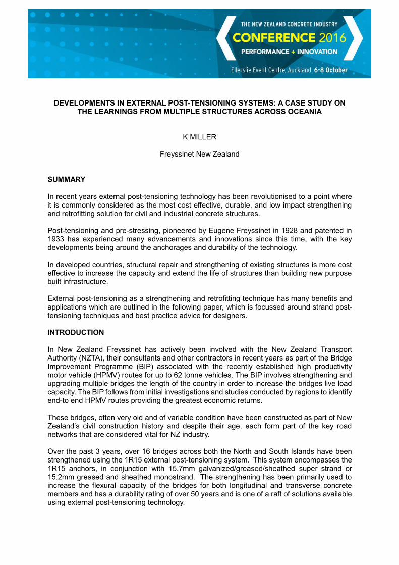
The following example, based around a project recently completed by Freyssinet on the Beecroft Bridge, M2 Motorway in Sydney illustrates these principles. For this project the existing two central piers were replaced with a new single pier as part of a lane widening design.
The contract was to assist the client with the design and detailing of the post-tensioning system and to supply, install and stress the external tendons on site. The scheme utilised innovative grouted unbonded post-tensioning tendons to provide the desired deflected profile while maintaining the future possibility of tendon replacement. This system is patented and extensively used in Europe but very rarely in Australia. It consists of using greased and sheathed strands injected with cement grout before stressing. The cement grout acts as a strand spacer and the grease and sheath provide corrosion protection to the strands. Strands are stressed with monostrand jacks to reduce jacking clearance. Tendons can be replaced strand by strand, by pulling through a new strand coupled to the old strand with compact couplers if this was ever required.
Step 1: Install external post-tensioned tendons profiled to maximize reaction forces at key locations
Step 2: Construct the new central pier
Step 3: Stress tendons (reaction forces are shown in red arrows)
Step 4: Remove two central piers with post-tensioning reaction forces providing the vertical supports

External post-tensioning is generally more effective than passive strengthening methods including steel bands, concrete thickening, additional reinforcement, and carbon fiber for structural strengthening. External post-tensioning provides an active force that does not require further deflection to activate the strengthening system, and provides negligible additional structural mass to the structure. External post-tensioning allows the determination of the exact magnitude of the force applied to the structure, whilst providing outstanding durability. External post-tensioning is generally user friendly with the construction and installation requiring minimal heavy lifting equipment and specialist handling techniques, especially if monostrand jacks can be used. Note that for all post-tensioning componentry it is strongly advised to specify materials by a reputable supplier with a strong track record, typically with European Technical Approval ETAG 013 or equivalent to ensure that high quality control and materials are used in the production of these components. Because of the highly loaded nature of post-tensioning materials and the fact that for external post-tensioning they are unbonded it is critical to ensure safety in design by specifying such requirements as the ETAG 013. Incorrect installation or the use of inferior materials in post-tensioning may result in failures that have the potential to cause serious harm and add significant costs to any project. Post-tensioning Components Strand Post-tensioned 7-wire strand of grade 1750MPa or 1830+MPa is typically used in Ø15.2mm (262KN breaking load) or Ø15.7mm (279KN breaking load) for civil and industrial structures. Ø12.7mm strand is generally being phased out of civil applications and is more common for post-tensioned slabs in building post-tensioning. It is now widely recognised that greased and sheathed strands, whether housed in a grouted duct or without ducting are the most effective, durable, and provide the most flexibility for future replacement or restressing.
External post-tensioning is subject to fatigue under live loads which is an important consideration when sizing the post-tensioned tendons. The fatigue behaviour is improved with the greased and sheathed strand, which eliminates the risk of grout cracking which can occur in a typical grouted tendon. The strand has two levels of corrosion protection barrier; grease and polyethylene sheathing (additionally the strand can also be galvanised if specified, providing 3 levels of corrosion protection). This will avoid the issue of load redistribution in case of a corroded strand in a multi strand tendon, and potential sudden breaking.
With “bonded” external post-tensioning systems, comprised of post-tensioning tendons made of bare strand injected with cement grout, a failure of one strand will transfer the force of this strand to the other strands by bonding through the grout. This will increase the stress level and failure risk on the remaining strands, and is why most international authorities now require that all external tendons use unbonded, greased and sheathed strand.
Additionally, the use of greased and sheathed strands offers a good maintenance solution due to its flexibility when it comes to stressing and de-stressing of each strand separately. Any twist during the installation and the subsequent strand damage during the stressing are avoided.
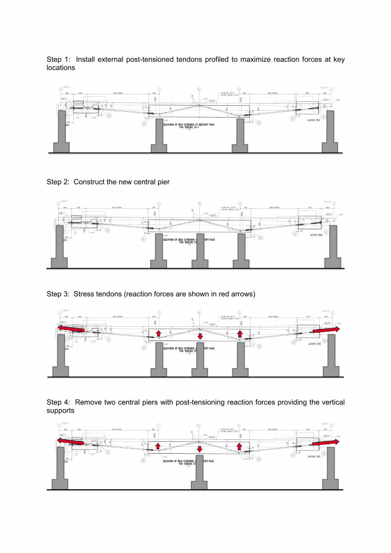
In New Zealand and for most applications which arise here the galvanised, greased, and sheathed monostrand (not housed in any duct) provides an ideal solution, providing greater than 50 years design life as well as proven performance in all of New Zealand’s environmental conditions. The HDPE sheath performs well against ageing as well as mechanical wear when installed correctly (particular care must be taken at the deviators).
With the monostrand system there is no limitation on the maximum length of the tendons/strand as the strand comes in large coils and can be cut to suit whatever length. This also provides huge benefits during construction/installation with monostrand having the added advantage of being easy to handle. Anchorages
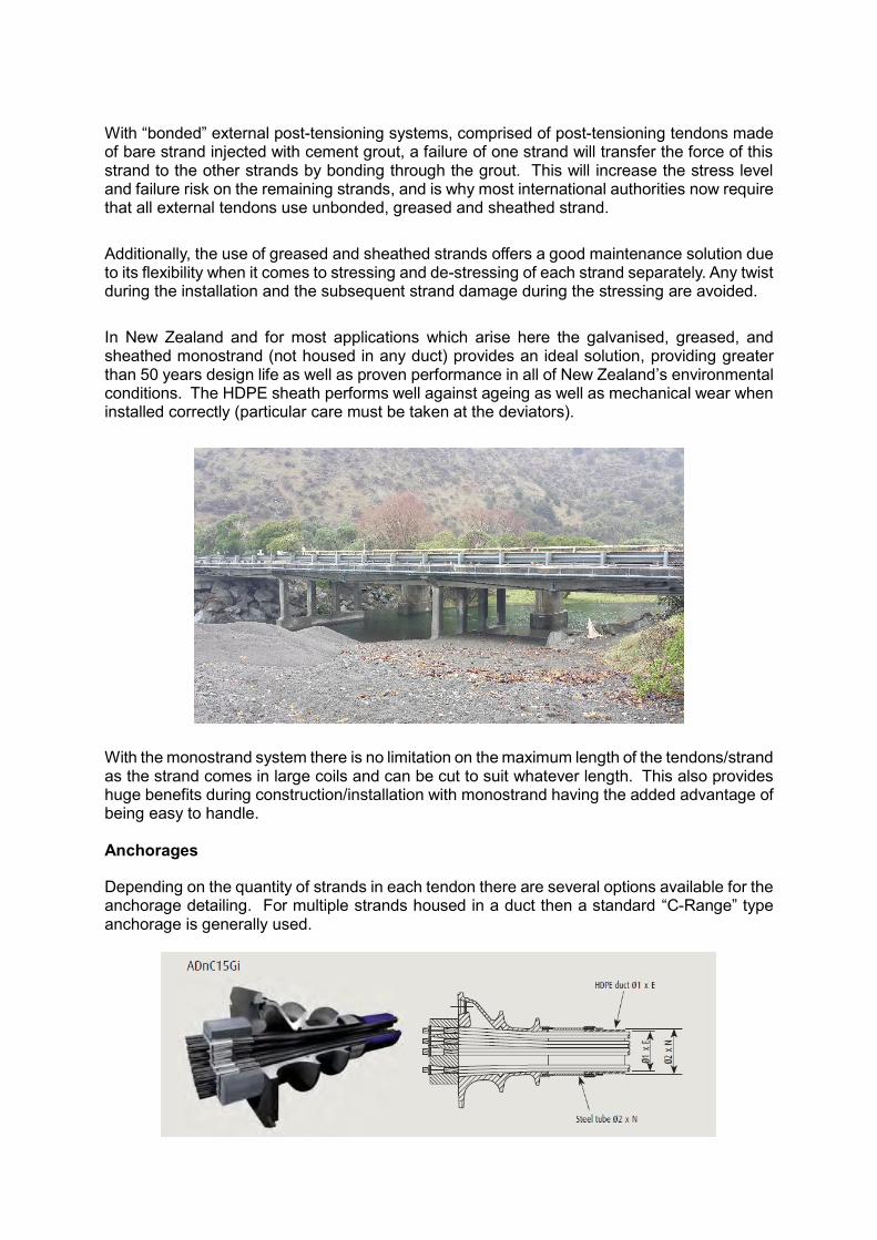
Depending on the quantity of strands in each tendon there are several options available for the anchorage detailing. For multiple strands housed in a duct then a standard “C-Range” type anchorage is generally used.

These can be housed inside a reinforced concrete “blister” which is connected to the main structure using either standard reinforcing bar dowels or stressed to the main structure using post-tensioned bars to utilise friction between the blister and the substrate. In this arrangement the stressed solution offers the most innovation and benefits with it providing a confining force to the anchorage trumplate, reduced time for concrete surface preparation (light scabbling completed by 3-pin scabblers to create concrete grooves is required - instead of deep scabbling), and minimising the number of core holes in the vertical web wall (lower risk to cut existing reinforcing steel or post-tensioning), particularly when using large diameter stress bars.
An alternative multistrand arrangement utilises a steel fabricated bracket which is then bolted or stressed to the wall with the anchor block seated directly on the bracket. This solution offers rapid installation however constructability (heavy to install) and durability can be a trade off to the concrete blister solution.

For monostrand applications the most efficient and innovative system available is the 1R15 system. This system eliminates the provision for the supply, fabrication and installation of large mechanically anchored steel welded brackets into the beams resulting to substantial savings for the project. With the 1R15 anchorage it requires just 1x cored hole per pair of anchorages (either side of a beam) vs many cored holes (up to 12-16 per anchor) with an alternative fabricated steel bracket anchorage solution, thus less chance of hitting existing reinforcing steel in an often degraded structure.
The 1R15 system features a compact solution, high performance and reliability as well as ease of installation eliminating use of steel frames and on-site cranage to install the system, with the weight of each anchor being only 19 and 22kg for the passive and active anchors respectively. The 1R15 system is installed in combination with a single greased and sheathed strand consisting of individually protected seven wire Ø15.7mm diameter strand with 279kN breaking load. It has an outstanding durability both mechanically and against ageing and uses cable stay bridge technology to ensure corrosion resistance both internally and externally.
These anchorages are constructed using ductile cast iron and protected from corrosion by a Rilson coating, which is a factory applied fusion bonded epoxy coating. Tests for salt spray resistance of the Rilson coating reported that coating adhesion remained good at the end of the test, and no corrosion was present at a cross cut in the coating, indicating that adhesion remained good even where the coating was damaged.

With standard maintenance procedures and monitoring of the structure, the anchorages will easily meet a 50 year minimum design life as can be expected and in fact have been approved for a 100 year design life in Australia. Inside the anchorage, the post-tensioning components are completely encapsulated in grease, which is the most efficient method of sealing from all moisture and oxygen, thus eliminating any possible corrosion reactions. The 1R15 anchorages function both with friction and bonding, both are used to achieve the required load transfer to the structure. The structural performance of these anchorages is mainly due to ripple shaped shear keys at the rear face of the anchorage and the friction created by the clamping effect of the stress bar. Testing and calculations carried out by the Freyssinet technical department proved a coefficient of friction of greater than 2.0 for the anchors and considering that the strand breaking load is 279KN, the anchors were shown to be able to resist greater than 500KN load. It has been validated by testing with 20 MPa concrete compressive strength (on cylinder) although in NZ the 1R15 has been successfully installed on concrete as low as 14MPa compressive strength. In the specific case of poor quality substrate it is advisable to get in touch with a specialist post-tensioning contractor to discuss possible solutions.
Surface preparation of the concrete substrate is advised to be complete using an epoxy such as Eponal 380 or Sikadur 30. The anchorage plates are then installed in place over the “wet” epoxy, anchored into place using a Freyssibar (stress bar) and the nuts snug tightened to fix the anchorage plate into place. Several days curing of the epoxy are required before stressing the Freyssibar, providing the clamping force to achieve the friction and bonding required to resist the strand forces. Once the epoxy has cured and the Freyssibars have been stressed to provide the clamping force to the anchorage the strands can be tensioned using monostrand jacks fitted with a curve nosed attachment. As per the photo above, by using these jacks the anchorage can be placed in restrictive locations, even right up against a wall or perpendicular beam. There are other obvious benefits in using monostrand jacks in terms of ease of handling and eliminating the requirement for rigging or blocks to lift/move the jacks. Deviators The deviator brackets themselves are best detailed by the design engineer as in most cases with every project being different the deviator brackets will be dependent on the type of strand system being used (multistrand vs monostrand), curvature of the deviation, site constraints, and so forth. For multistrand deviators similar detailing to the anchor blocks can be used with either concrete blisters or steel brackets. For monostrand applications it is important for multi-tube inserts/spacers to be used. These are typically installed and grouted inside a hollow tube section or similar which is part of the main deviator bracket.

It is important to ensure that the correct bend radius and separation of strands is achieved and it is recommended to use HDPE diabolos at the ends to avoid any damage to the strand. Where the strand passes through a diaphragm it is advisable to use a similar detail inside the concrete core as to that used for the deviator brackets. Installing the multi-tube inserts/spacers inside the cored hole and grouting around them to fix in place. Typically 1-4 strands per deviator tube is the most efficient to avoid crossing/touching of strands for these monostrand applications
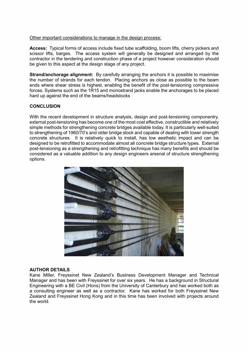
Other important considerations to manage in the design process: Access: Typical forms of access include fixed tube scaffolding, boom lifts, cherry pickers and scissor lifts, barges. The access system will generally be designed and arranged by the contractor in the tendering and construction phase of a project however consideration should be given to this aspect at the design stage of any project. Strand/anchorage alignment: By carefully arranging the anchors it is possible to maximise the number of strands for each tendon. Placing anchors as close as possible to the beam ends where shear stress is highest, enabling the benefit of the post-tensioning compressive forces. Systems such as the 1R15 and monostrand jacks enable the anchorages to be placed hard up against the end of the beams/headstocks CONCLUSION With the recent development in structure analysis, design and post-tensioning componentry, external post-tensioning has become one of the most cost effective, constructible and relatively simple methods for strengthening concrete bridges available today. It is particularly well-suited to strengthening of 1960/70’s and older bridge stock and capable of dealing with lower strength concrete structures. It is relatively quick to install, has low aesthetic impact and can be designed to be retrofitted to accommodate almost all concrete bridge structure types. External post-tensioning as a strengthening and retrofitting technique has many benefits and should be considered as a valuable addition to any design engineers arsenal of structure strengthening options.
AUTHOR DETAILS Kane Miller, Freyssinet New Zealand’s Business Development Manager and Technical Manager and has been with Freyssinet for over six years. He has a background in Structural Engineering with a BE Civil (Hons) from the University of Canterbury and has worked both as a consulting engineer as well as a contractor. Kane has worked for both Freyssinet New Zealand and Freyssinet Hong Kong and in this time has been involved with projects around the world.