development of vertical submerged arc welding method for
TRANSCRIPT
55
Vo l . 4 3 N o . 2 2 010
1. Introduction
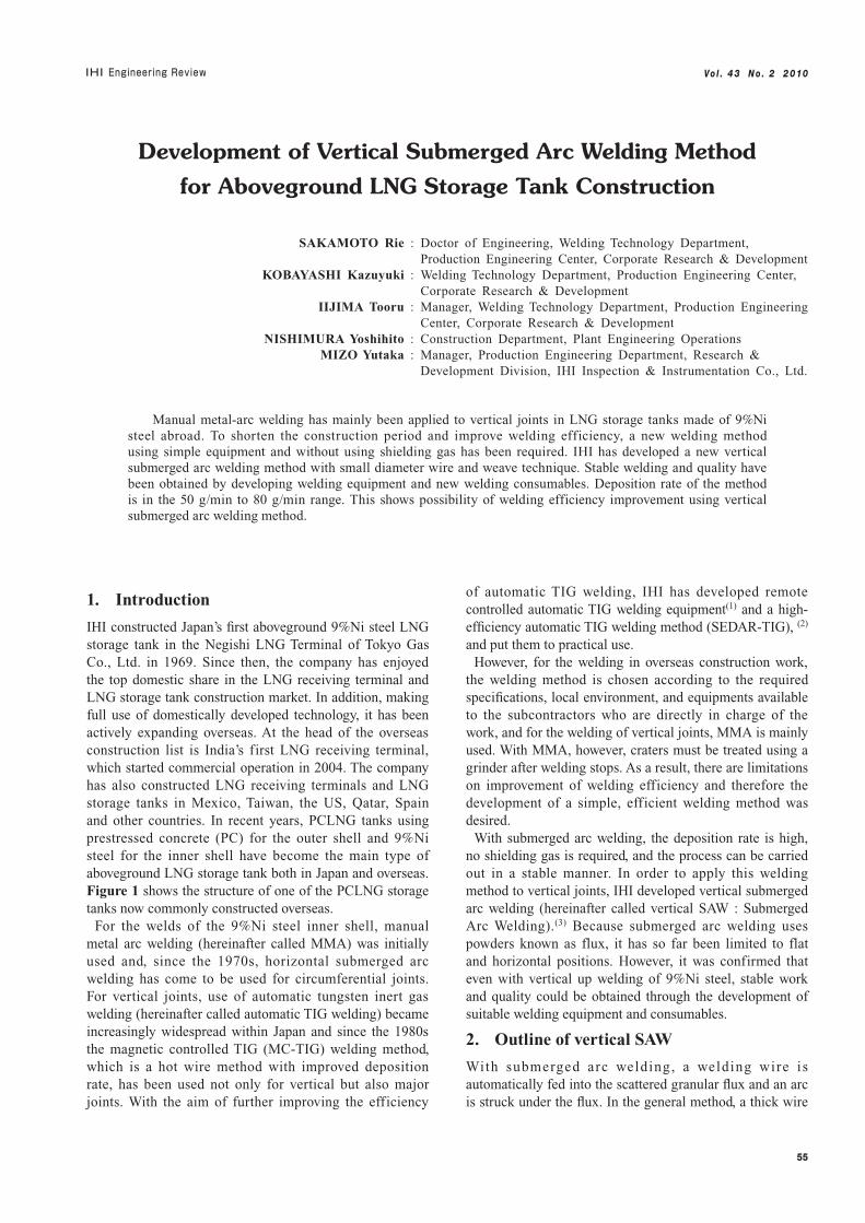
IHI constructed Japan’s first aboveground 9%Ni steel LNG storage tank in the Negishi LNG Terminal of Tokyo Gas Co., Ltd. in 1969. Since then, the company has enjoyed the top domestic share in the LNG receiving terminal and LNG storage tank construction market. In addition, making full use of domestically developed technology, it has been actively expanding overseas. At the head of the overseas construction list is India’s first LNG receiving terminal, which started commercial operation in 2004. The company has also constructed LNG receiving terminals and LNG storage tanks in Mexico, Taiwan, the US, Qatar, Spain and other countries. In recent years, PCLNG tanks using prestressed concrete (PC) for the outer shell and 9%Ni steel for the inner shell have become the main type of aboveground LNG storage tank both in Japan and overseas. Figure 1 shows the structure of one of the PCLNG storage tanks now commonly constructed overseas.
For the welds of the 9%Ni steel inner shell, manual metal arc welding (hereinafter called MMA) was initially used and, since the 1970s, horizontal submerged arc welding has come to be used for circumferential joints. For vertical joints, use of automatic tungsten inert gas welding (hereinafter called automatic TIG welding) became increasingly widespread within Japan and since the 1980s the magnetic controlled TIG (MC-TIG) welding method, which is a hot wire method with improved deposition rate, has been used not only for vertical but also major joints. With the aim of further improving the efficiency
of automatic TIG welding, IHI has developed remote controlled automatic TIG welding equipment(1) and a high-efficiency automatic TIG welding method (SEDAR-TIG), (2)
and put them to practical use.However, for the welding in overseas construction work,
the welding method is chosen according to the required specifications, local environment, and equipments available to the subcontractors who are directly in charge of the work, and for the welding of vertical joints, MMA is mainly used. With MMA, however, craters must be treated using a grinder after welding stops. As a result, there are limitations on improvement of welding efficiency and therefore the development of a simple, efficient welding method was desired.
With submerged arc welding, the deposition rate is high, no shielding gas is required, and the process can be carried out in a stable manner. In order to apply this welding method to vertical joints, IHI developed vertical submerged arc welding (hereinafter called vertical SAW : Submerged Arc Welding).(3) Because submerged arc welding uses powders known as flux, it has so far been limited to flat and horizontal positions. However, it was confirmed that even with vertical up welding of 9%Ni steel, stable work and quality could be obtained through the development of suitable welding equipment and consumables.
2. Outline of vertical SAW
With submerged arc welding, a welding wire is automatically fed into the scattered granular flux and an arc is struck under the flux. In the general method, a thick wire
Development of Vertical Submerged Arc Welding Method
for Aboveground LNG Storage Tank Construction
SAKAMOTO Rie : Doctor of Engineering, Welding Technology Department, Production Engineering Center, Corporate Research & Development KOBAYASHI Kazuyuki : Welding Technology Department, Production Engineering Center, Corporate Research & Development IIJIMA Tooru : Manager, Welding Technology Department, Production Engineering Center, Corporate Research & Development NISHIMURA Yoshihito : Construction Department, Plant Engineering Operations MIZO Yutaka : Manager, Production Engineering Department, Research & Development Division, IHI Inspection & Instrumentation Co., Ltd.
Manual metal-arc welding has mainly been applied to vertical joints in LNG storage tanks made of 9%Ni steel abroad. To shorten the construction period and improve welding efficiency, a new welding method using simple equipment and without using shielding gas has been required. IHI has developed a new vertical submerged arc welding method with small diameter wire and weave technique. Stable welding and quality have been obtained by developing welding equipment and new welding consumables. Deposition rate of the method is in the 50 g/min to 80 g/min range. This shows possibility of welding efficiency improvement using vertical submerged arc welding method.
56
Vo l . 4 3 N o . 2 2 010
4.8 mm in diameter is used and a large current of several hundred amperes is passed during welding, so that welding efficiency is high. In contrast, the vertical SAW developed by IHI uses a thin wire, 1.2 mm in diameter, and moves it in the manner of a weaving motion during welding. A low current range is used, so that a feature of this method is its ability to hold down the welding heat input and control bead shape.
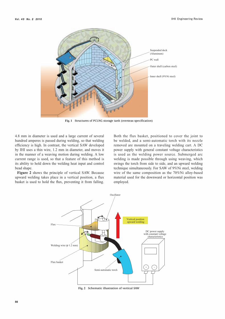
Figure 2 shows the principle of vertical SAW. Because upward welding takes place in a vertical position, a flux basket is used to hold the flux, preventing it from falling.
Both the flux basket, positioned to cover the joint to be welded, and a semi-automatic torch with its nozzle removed are mounted on a traveling welding cart. A DC power supply with general constant voltage characteristics is used as the welding power source. Submerged arc welding is made possible through using weaving, which swings the torch from side to side, and an upward welding technique simultaneously. For SAW of 9%Ni steel, welding wire of the same composition as the 70%Ni alloy-based material used for the downward or horizontal position was employed.
Suspended deck(Aluminum)
PC wall
Outer shell (carbon steel)
Inner shell (9%Ni steel)
Fig. 1 Structures of PCLNG storage tank (overseas specification)
Vertical position upward welding
Oscillator
Flux basket
Semi-automatic torch
Flux
Welding wire (f 1.2 mm)
−+
DC power supply with constant voltage
characteristics
Fig. 2 Schematic illustration of vertical SAW
57
Vo l . 4 3 N o . 2 2 010
3. Development of 9%Ni steel vertical SAW welding consumables
3.1 Comparison of welding usability using commercial fluxes
Pr ior to the development of dedica ted weld ing consumables, the welding usability of vertical SAW was evaluated using commercial fluxes. For this comparison, not only fluxes for 9%Ni steel but also those for other uses were included. The types of evaluation included bead shape smoothness, slag (nonmetallic substances generated on the surface of the weld) detachability, and quality determined by radiographic testing (hereinafter called RT). In the test, the carbon steel plate used was of thickness 19 mm with a U-slot 20 mm wide and 10 mm deep, and a 70%Ni alloy-based material 1.2 mm in diameter was used for the welding wire.
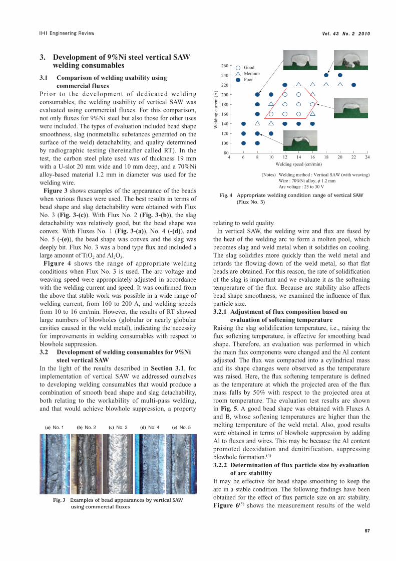
Figure 3 shows examples of the appearance of the beads when various fluxes were used. The best results in terms of bead shape and slag detachability were obtained with Flux No. 3 (Fig. 3-(c)). With Flux No. 2 (Fig. 3-(b)), the slag detachability was relatively good, but the bead shape was convex. With Fluxes No. 1 (Fig. 3-(a)), No. 4 (-(d)), and No. 5 (-(e)), the bead shape was convex and the slag was deeply bit. Flux No. 3 was a bond type flux and included a large amount of TiO2 and Al2O3.
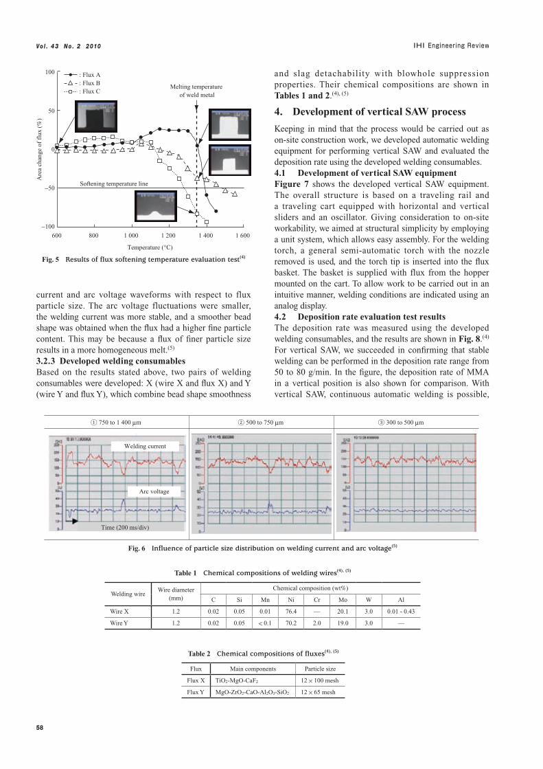
Figure 4 shows the range of appropriate welding conditions when Flux No. 3 is used. The arc voltage and weaving speed were appropriately adjusted in accordance with the welding current and speed. It was confirmed from the above that stable work was possible in a wide range of welding current, from 160 to 200 A, and welding speeds from 10 to 16 cm/min. However, the results of RT showed large numbers of blowholes (globular or nearly globular cavities caused in the weld metal), indicating the necessity for improvements in welding consumables with respect to blowhole suppression.3.2 Development of welding consumables for 9%Ni
steel vertical SAWIn the light of the results described in Section 3.1, for implementation of vertical SAW we addressed ourselves to developing welding consumables that would produce a combination of smooth bead shape and slag detachability, both relating to the workability of multi-pass welding, and that would achieve blowhole suppression, a property
relating to weld quality.In vertical SAW, the welding wire and flux are fused by
the heat of the welding arc to form a molten pool, which becomes slag and weld metal when it solidifies on cooling. The slag solidifies more quickly than the weld metal and retards the flowing-down of the weld metal, so that flat beads are obtained. For this reason, the rate of solidification of the slag is important and we evaluate it as the softening temperature of the flux. Because arc stability also affects bead shape smoothness, we examined the influence of flux particle size.3.2.1 Adjustment of flux composition based on
evaluation of softening temperatureRaising the slag solidification temperature, i.e., raising the flux softening temperature, is effective for smoothing bead shape. Therefore, an evaluation was performed in which the main flux components were changed and the Al content adjusted. The flux was compacted into a cylindrical mass and its shape changes were observed as the temperature was raised. Here, the flux softening temperature is defined as the temperature at which the projected area of the flux mass falls by 50% with respect to the projected area at room temperature. The evaluation test results are shown in Fig. 5. A good bead shape was obtained with Fluxes A and B, whose softening temperatures are higher than the melting temperature of the weld metal. Also, good results were obtained in terms of blowhole suppression by adding Al to fluxes and wires. This may be because the Al content promoted deoxidation and denitrif ication, suppressing blowhole formation.(4)
3.2.2 Determination of flux particle size by evaluation of arc stability
It may be effective for bead shape smoothing to keep the arc in a stable condition. The following findings have been obtained for the effect of flux particle size on arc stability. Figure 6(5) shows the measurement results of the weld
(a) No. 1 (b) No. 2 (c) No. 3 (d) No. 4 (e) No. 5
Fig. 3 Examples of bead appearances by vertical SAW using commercial fluxes
4 6 8 10 12 14 16 18 20 22 2480
100
120
140
160
180
200
220
240
260
Welding speed (cm/min)
Wel
ding
cur
rent
(A
)
(Notes) Welding method : Vertical SAW (with weaving) Wire : 70%Ni alloy, f 1.2 mm Arc voltage : 25 to 30 V
� : Good� : Medium� : Poor
Fig. 4 Appropriate welding condition range of vertical SAW (Flux No. 3)
58
Vo l . 4 3 N o . 2 2 010
current and arc voltage waveforms with respect to flux particle size. The arc voltage fluctuations were smaller, the welding current was more stable, and a smoother bead shape was obtained when the flux had a higher fine particle content. This may be because a flux of finer particle size results in a more homogeneous melt.(5)
3.2.3 Developed welding consumablesBased on the results stated above, two pairs of welding consumables were developed: X (wire X and flux X) and Y (wire Y and flux Y), which combine bead shape smoothness
and slag detachability with blowhole suppression properties. Their chemical compositions are shown in Tables 1 and 2.(4), (5)
4. Development of vertical SAW process
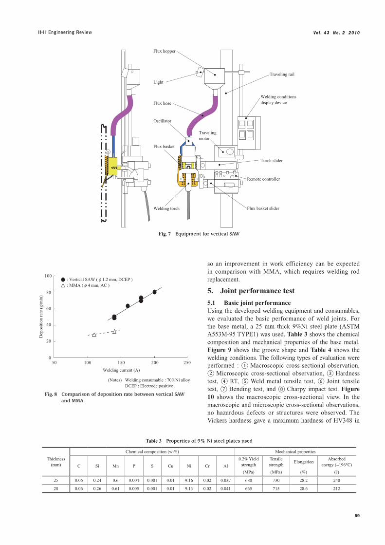
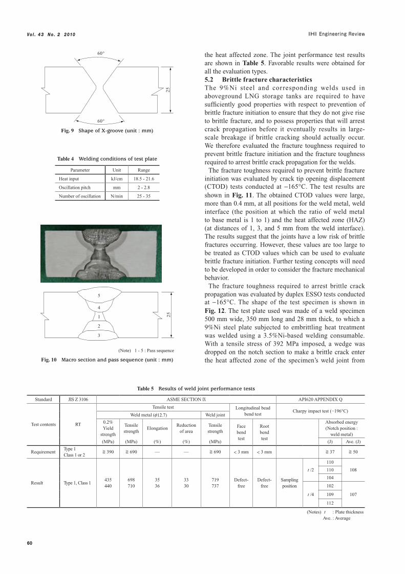
Keeping in mind that the process would be carried out as on-site construction work, we developed automatic welding equipment for performing vertical SAW and evaluated the deposition rate using the developed welding consumables.4.1 Development of vertical SAW equipmentFigure 7 shows the developed vertical SAW equipment. The overall structure is based on a traveling rail and a traveling cart equipped with horizontal and vertical sliders and an oscillator. Giving consideration to on-site workability, we aimed at structural simplicity by employing a unit system, which allows easy assembly. For the welding torch, a general semi-automatic torch with the nozzle removed is used, and the torch tip is inserted into the flux basket. The basket is supplied with flux from the hopper mounted on the cart. To allow work to be carried out in an intuitive manner, welding conditions are indicated using an analog display.4.2 Deposition rate evaluation test resultsThe deposition rate was measured using the developed welding consumables, and the results are shown in Fig. 8.(4) For vertical SAW, we succeeded in confirming that stable welding can be performed in the deposition rate range from 50 to 80 g/min. In the figure, the deposition rate of MMA in a vertical position is also shown for comparison. With vertical SAW, continuous automatic welding is possible,
600 800 1 000 1 200 1 400 1 600
Temperature (°C)
Are
a ch
ange
of
flux
(%
)
50
0
−50
−100
Softening temperature line
100 : Flux A : Flux B : Flux C
Melting temperature of weld metal
Fig. 5 Results of flux softening temperature evaluation test(4)
① 750 to 1 400 µm ② 500 to 750 µm ③ 300 to 500 µm
Arc voltage
Time (200 ms/div)
Welding current
Fig. 6 Influence of particle size distribution on welding current and arc voltage(5)
Table 1 Chemical compositions of welding wires(4), (5)
Welding wireWire diameter
(mm)
Chemical composition (wt%)
C Si Mn Ni Cr Mo W Al
Wire X 1.2 0.02 0.05 0.01 76.4 — 20.1 3.0 0.01 - 0.43
Wire Y 1.2 0.02 0.05 < 0.1 70.2 2.0 19.0 3.0 —
Table 2 Chemical compositions of fluxes(4), (5)
Flux Main components Particle size
Flux X TiO2-MgO-CaF2 12 × 100 mesh
Flux Y MgO-ZrO2-CaO-Al2O3-SiO2 12 × 65 mesh
59
Vo l . 4 3 N o . 2 2 010
so an improvement in work efficiency can be expected in comparison with MMA, which requires welding rod replacement.
5. Joint performance test
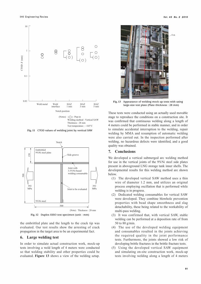
5.1 Basic joint performanceUsing the developed welding equipment and consumables, we evaluated the basic performance of weld joints. For the base metal, a 25 mm thick 9%Ni steel plate (ASTM A553M-95 TYPE1) was used. Table 3 shows the chemical composition and mechanical properties of the base metal. Figure 9 shows the groove shape and Table 4 shows the welding conditions. The following types of evaluation were performed : ① Macroscopic cross-sectional observation, ② Microscopic cross-sectional observation, ③ Hardness test, ④ RT, ⑤ Weld metal tensile test, ⑥ Joint tensile test, ⑦ Bending test, and ⑧ Charpy impact test. Figure 10 shows the macroscopic cross-sectional view. In the macroscopic and microscopic cross-sectional observations, no hazardous defects or structures were observed. The Vickers hardness gave a maximum hardness of HV348 in
0
20
40
60
80
100
50 100 150 200 250
Welding current (A)
Dep
osit
ion
rate
(g/
min
)
(Notes) Welding consumable : 70%Ni alloy DCEP : Electrode positive
: Vertical SAW ( f 1.2 mm, DCEP ) : MMA ( f 4 mm, AC )
Fig. 8 Comparison of deposition rate between vertical SAW and MMA
Flux hopper
Traveling rail
Light
Welding conditions display device
Traveling motor
Torch slider
Remote controller
Flux basket slider
Oscillator
Flux hose
Flux basket
Welding torch
Fig. 7 Equipment for vertical SAW
Table 3 Properties of 9% Ni steel plates used
Thickness(mm)
Chemical composition (wt%) Mechanical properties
C Si Mn P S Cu Ni Cr Al
0.2% Yield strength
Tensile strength
ElongationAbsorbed
energy (−196°C)
(MPa) (MPa) (%) (J)
25 0.06 0.24 0.6 0.004 0.001 0.01 9.16 0.02 0.037 680 730 28.2 240
28 0.06 0.26 0.61 0.005 0.001 0.01 9.13 0.02 0.041 665 715 28.6 212
60
Vo l . 4 3 N o . 2 2 010
the heat affected zone. The joint performance test results are shown in Table 5. Favorable results were obtained for all the evaluation types.5.2 Brittle fracture characteristicsThe 9%Ni steel and cor responding welds used in aboveground LNG storage tanks are required to have sufficiently good properties with respect to prevention of brittle fracture initiation to ensure that they do not give rise to brittle fracture, and to possess properties that will arrest crack propagation before it eventually results in large-scale breakage if brittle cracking should actually occur. We therefore evaluated the fracture toughness required to prevent brittle fracture initiation and the fracture toughness required to arrest brittle crack propagation for the welds.
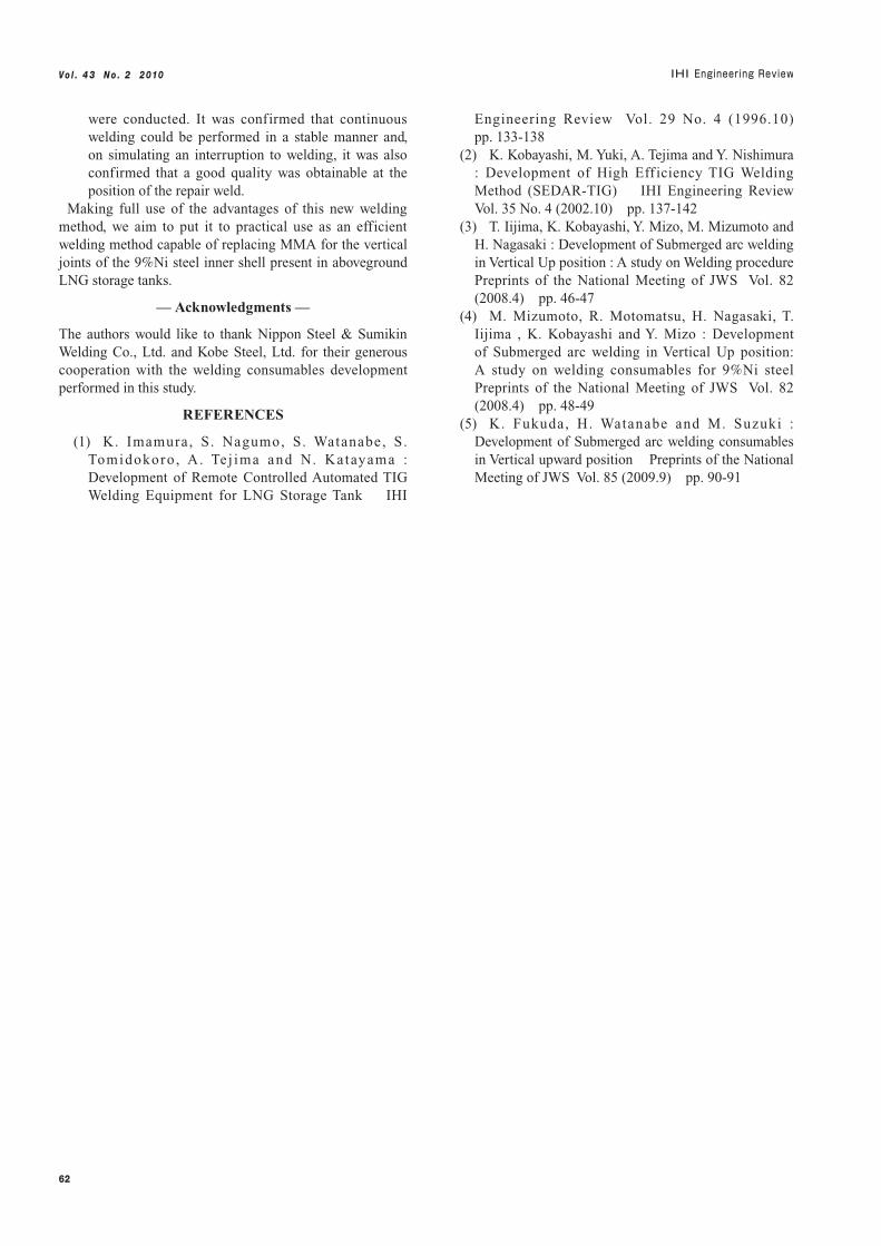
The fracture toughness required to prevent brittle fracture initiation was evaluated by crack tip opening displacement (CTOD) tests conducted at −165°C. The test results are shown in Fig. 11. The obtained CTOD values were large, more than 0.4 mm, at all positions for the weld metal, weld interface (the position at which the ratio of weld metal to base metal is 1 to 1) and the heat affected zone (HAZ) (at distances of 1, 3, and 5 mm from the weld interface). The results suggest that the joints have a low risk of brittle fractures occurring. However, these values are too large to be treated as CTOD values which can be used to evaluate brittle fracture initiation. Further testing concepts will need to be developed in order to consider the fracture mechanical behavior.
The fracture toughness required to arrest brittle crack propagation was evaluated by duplex ESSO tests conducted at −165°C. The shape of the test specimen is shown in Fig. 12. The test plate used was made of a weld specimen 500 mm wide, 350 mm long and 28 mm thick, to which a 9%Ni steel plate subjected to embrittling heat treatment was welded using a 3.5%Ni-based welding consumable. With a tensile stress of 392 MPa imposed, a wedge was dropped on the notch section to make a brittle crack enter the heat affected zone of the specimen’s weld joint from
Table 4 Welding conditions of test plate
Parameter Unit Range
Heat input kJ/cm 18.5 - 21.6
Oscillation pitch mm 2 - 2.8
Number of oscillation N/min 25 - 35
60°
60°
25
Fig. 9 Shape of X-groove (unit : mm)
1
2
3
4
5
(Note) 1 - 5 : Pass sequence
25
Fig. 10 Macro section and pass sequence (unit : mm)
Table 5 Results of weld joint performance tests
Standard JIS Z 3106 ASME SECTION IX API620 APPENDIX Q
Test contents RT
Tensile test Longitudinal bead bend test
Charpy impact test (−196°C)Weld metal (f12.7) Weld joint
0.2% Yield
strength
Tensile strength
ElongationReduction
of areaTensile strength
Face bend test
Root bend test
Absorbed energy(Notch position :
weld metal)
(MPa) (MPa) (%) (%) (MPa) (J) Ave. (J)
RequirementType 1Class 1 or 2
≧ 390 ≧ 690 — — ≧ 690 < 3 mm < 3 mm ≧ 37 ≧ 50
Result Type 1, Class 1435440
698710
3536
3330
719737
Defect-free
Defect-free
Sampling position
t /2
110
108110
104
t /4
102
107109
112
(Notes) t : Plate thickness Ave. : Average
61
Vo l . 4 3 N o . 2 2 010
the embrittled plate and the length to the crack tip was evaluated. Our test results show the arresting of crack propagation in the target area to be an experimental fact.
6. Large welding test
In order to simulate actual construction work, mock-up tests involving a weld length of 4 meters were conducted so that welding stability and other properties could be evaluated. Figure 13 shows a view of the welding setup.
These tests were conducted using an actually used movable stage to reproduce the conditions on a construction site. It was confirmed that continuous welding along a length of 4 meters could be performed in stable manner, and in order to simulate accidental interruption to the welding, repair welding by MMA and resumption of automatic welding were also carried out. In the inspection performed after welding, no hazardous defects were identified, and a good quality was obtained.
7. Conclusions
We developed a vertical submerged arc welding method for use in the vertical joints of the 9%Ni steel side plates present in aboveground LNG storage tank inner shells. The developmental results for this welding method are shown below.
(1) The developed vertical SAW method uses a thin wire of diameter 1.2 mm, and utilizes an original process employing oscillation that is performed while welding is in progress.
(2) Dedicated welding consumables for vertical SAW were developed. They combine blowhole prevention properties with bead shape smoothness and slag detachability, these being related to the workability of multi-pass welding.
(3) It was confirmed that, with vertical SAW, stable welding can be performed at a deposition rate of from 50 to 80 g/min.
(4) The use of the developed welding equipment and consumables resulted in the joints achieving the required quality in the joint performance tests. Furthermore, the joints showed a low risk of developing brittle fractures in the brittle fracture tests.
(5) Using the developed vertical SAW equipment and simulating on-site construction work, mock-up tests involving welding along a length of 4 meters
4 m
Fig. 13 Appearance of welding mock up tests with using large-size test plate (Plate thickness : 28 mm)
Notch
Side groove
392MPa
392MPa
Embrittled 9%Ni steel plate
Joint with 3.5%Ni-based welding consumable
9%Ni steel
Joint to be evaluated
500
150
500
(Note) Thickness : 28 mm
Fig. 12 Duplex ESSO test specimen (unit : mm)
0.01
0.1
1
10
HAZ1 mm
Weld interface
Weld metal
CT
OD
d (
mm
)
HAZ3 mm
HAZ5 mm
Notch position
(Notes) ( ) : Pop-in Welding method : Vertical SAW Thickness : 28 mm Test temperature : −165°C
Fig. 11 CTOD values of welding joint by vertical SAW
62
Vo l . 4 3 N o . 2 2 010
were conducted. It was confirmed that continuous welding could be performed in a stable manner and, on simulating an interruption to welding, it was also confirmed that a good quality was obtainable at the position of the repair weld.
Making full use of the advantages of this new welding method, we aim to put it to practical use as an efficient welding method capable of replacing MMA for the vertical joints of the 9%Ni steel inner shell present in aboveground LNG storage tanks.
— Acknowledgments —
The authors would like to thank Nippon Steel & Sumikin Welding Co., Ltd. and Kobe Steel, Ltd. for their generous cooperation with the welding consumables development performed in this study.
REFERENCES
(1) K. Imamura, S. Nagumo, S. Watanabe, S. Tomidokoro , A. Te j ima and N. Katayama : Development of Remote Controlled Automated TIG Welding Equipment for LNG Storage Tank IHI
Engineering Review Vol. 29 No. 4 (1996.10) pp. 133-138
(2) K. Kobayashi, M. Yuki, A. Tejima and Y. Nishimura : Development of High Eff iciency TIG Welding Method (SEDAR-TIG) IHI Engineering Review Vol. 35 No. 4 (2002.10) pp. 137-142
(3) T. Iijima, K. Kobayashi, Y. Mizo, M. Mizumoto and H. Nagasaki : Development of Submerged arc welding in Vertical Up position : A study on Welding procedure Preprints of the National Meeting of JWS Vol. 82 (2008.4) pp. 46-47
(4) M. Mizumoto, R. Motomatsu, H. Nagasaki, T. Iijima , K. Kobayashi and Y. Mizo : Development of Submerged arc welding in Vertical Up position: A study on welding consumables for 9%Ni steel Preprints of the National Meeting of JWS Vol. 82 (2008.4) pp. 48-49
(5) K. Fukuda, H. Watanabe and M. Suzuki : Development of Submerged arc welding consumables in Vertical upward position Preprints of the National Meeting of JWS Vol. 85 (2009.9) pp. 90-91