development of tqc01, a 90 mm nb sn model quadrupole for
TRANSCRIPT

BNL-78058-2007-JA
Development of TQC01, a 90 mm Nb3 Sn Model Quadrupole for LHC Upgrade Based on SS Collar
R.C. Bossert, G. Ambrosio, N. Andreev, E. Barzi, S. Caspi, D.R. Dietderich, P. Ferracin, A. Ghosh, S.A. Gourlay,
A.R. Hafalia, C.R. Hannaford, V.S. Kashikhin, V.V. Kashikhin, A.F. Lietzke, S. Mattafirri, A.D. McInturff, I. Novitski,
G.L. Sabbi, D. Turrioni, G. Whitson, R. Yamada, A.V. Zlobin
Accepted for Publication in IEEE Transaction on Applied Superconductivity (2006)
June 5, 2007
Superconducting Magnet Division
Brookhaven National Laboratory P.O. Box 5000
Upton, NY 11973-5000 www.bnl.gov
Notice: This manuscript has been authored by employees of Brookhaven Science Associates, LLC under Contract No. DE-AC02-98CH10886 with the U.S. Department of Energy. The publisher by accepting the manuscript for publication acknowledges that the United States Government retains a non-exclusive, paid-up, irrevocable, world-wide license to publish or reproduce the published form of this manuscript, or allow others to do so, for United States Government purposes.

DISCLAIMER
This report was prepared as an account of work sponsored by an agency of the United States Government. Neither the United States Government nor any agency thereof, nor any of their employees, nor any of their contractors, subcontractors, or their employees, makes any warranty, express or implied, or assumes any legal liability or responsibility for the accuracy, completeness, or any third party’s use or the results of such use of any information, apparatus, product, or process disclosed, or represents that its use would not infringe privately owned rights. Reference herein to any specific commercial product, process, or service by trade name, trademark, manufacturer, or otherwise, does not necessarily constitute or imply its endorsement, recommendation, or favoring by the United States Government or any agency thereof or its contractors or subcontractors. The views and opinions of authors expressed herein do not necessarily state or reflect those of the United States Government or any agency thereof.

370 IEEE TRANSACTIONS ON APPLIED SUPERCONDUCTIVITY, VOL. 16, NO. 2, JUNE 2006
Development of TQC01, a 90 mm Nb3 Sn ModelQuadrupole for LHC Upgrade Based on SS Collar
R. C. Bossert, G. Ambrosio, N. Andreev, E. Barzi, S. Caspi, D. R. Dietderich, P. Ferracin, A. Ghosh,S. A. Gourlay, A. R. Hafalia, C. R. Hannaford, V. S. Kashikhin, V. V. Kashikhin, A. F. Lietzke, S. Mattafirri,
A. D. McInturff, I. Novitski, G. L. Sabbi, D. Turrioni, G. Whitson, R. Yamada, and A. V. Zlobin
Abstract—As a first step toward the development of a large-aper-ture Nb3Sn superconducting quadrupole for the Large HadronCollider (LHC) luminosity upgrade, two-layer technologicalquadrupole models (TQS01 at LBNL and TQC01 at Fermilab)are being constructed within the framework of the US LHCAccelerator Research Program (LARP). Both models use thesame coil design, but have different coil support structures. Thispaper describes the TQC01 design, fabrication technology andsummarizes its main parameters.
Index Terms—Collars, LARP, LHC IR, Nb3Sn, quadrupolemagnet, skin, yoke.
I. INTRODUCTION
AN IMPORTANT objective of the US LHC Acceler-ator Research Program (LARP) is to develop a
quadrupole for an eventual LHC upgrade [1]. US labs (FNAL,BNL and LBL) are collaborating to build and test the ini-tial short models. Two different structures, using the sametwo-layer, 90 mm aperture shell type epoxy impregnated coildesign, are being pursued. The TQS01 structure was developedand tested on a dummy coil at LBNL. In this approach, coils areassembled and reacted against an outer aluminum shell usingkeys and bladders [2]. A short quadrupole model TQC01 basedon stainless steel collars supported by an iron yoke and thickSS skin is being developed at Fermilab. A short 0.3 m longmechanical model is being fabricated and tested to verify theresults of the mechanical analysis. The model is instrumentedwith strain gauges installed on its main components. Stressdistribution is monitored during model assembly at room tem-perature and after cooling down to liquid nitrogen temperature.This paper describes the TQC01 design, fabrication technologyand summarizes its main parameters. Initial coil fabricationexperience is reported. ANSYS 2D calculations and measure-ments on a mechanical model are shown.
Manuscript received September 20, 2005. This work was supported by the Di-rector, Office of Energy Research, Office of High Energy and Nuclear Physics,High Energy Physics Division, U. S. Department of Energy, under ContractDE-AC02-05CH11231.
R. Bossert, G. Ambrosio, N. Andreev, E. Barzi, V. S. Kashikhin, V. V.Kashikhin, I. Novitsky, D. Turrioni, G. Whitson, R. Yamada, and A. V. Zlobinare with Fermilab National Accelerator Laboratory, Batavia, IL 60510-0500USA (e-mail: [email protected].
S. Caspi, D. R. Dietderich, P. Ferracin, S. A. Gourlay, A. R. Hafalia, C. R.Hannaford, A. F. Lietzke, S. Mattafirri, A. D. McInturff, and G. L. Sabbi arewith Lawrence Berkeley National Lab, Berkeley, CA 94720 USA.
A. Ghosh is with Brookhaven National Laboratory, Upton, NY 11973 USA.Digital Object Identifier 10.1109/TASC.2006.871320
Fig. 1. TQ magnet coil cross section.
TABLE ITQ SPECIFICATIONS
II. MAGNET DESIGN AND ANALYSIS
A. Cable and Cross Section
The TQ coil design consists of a 2-layer configura-tion with a 90 mm bore and one wedge in the inner layer (Fig. 1).The cable design was developed in collaboration with BNL andLBNL [3]. It is made of 27 strands each .7 mm in dia., with anominal keystone angle of 1.0 degrees, width of 10.05 mm andmid-thickness of 1.26 mm. Cable for the first set of TQ mag-nets will be made from MJR strand that is currently available inquantities sufficient for two short models. Subsequent magnetswill use RRP strand currently under development with higher
[3]. TQC01 specifications are shown in Table I.
B. Structure
The TQC mechanical structure is shown in Fig. 2. It is basedon the structure of the MQXB quadrupoles built at Fermilab forthe LHC interaction region [4]. MQXB collars are used, withinner layer poles removed and outer layer poles retained for coil
1051-8223/$20.00 © 2006 IEEE
BOSSERT et al.: DEVELOPMENT OF TQC01 371
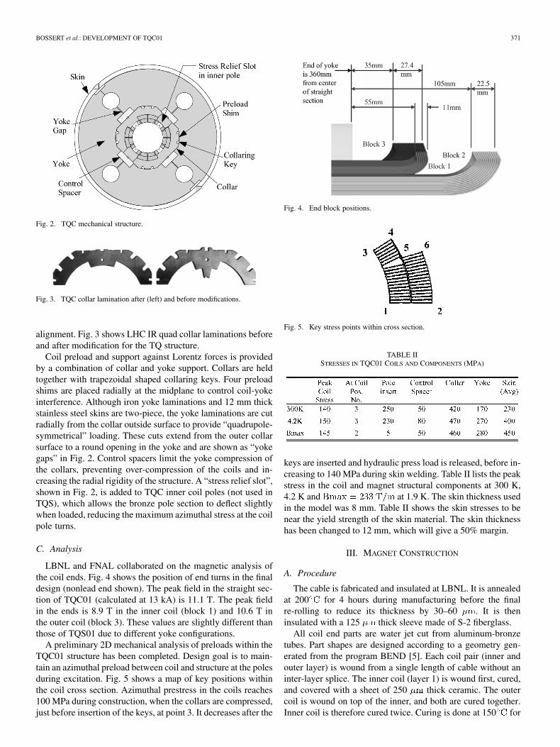
Fig. 2. TQC mechanical structure.
Fig. 3. TQC collar lamination after (left) and before modifications.
alignment. Fig. 3 shows LHC IR quad collar laminations beforeand after modification for the TQ structure.
Coil preload and support against Lorentz forces is providedby a combination of collar and yoke support. Collars are heldtogether with trapezoidal shaped collaring keys. Four preloadshims are placed radially at the midplane to control coil-yokeinterference. Although iron yoke laminations and 12 mm thickstainless steel skins are two-piece, the yoke laminations are cutradially from the collar outside surface to provide “quadrupole-symmetrical” loading. These cuts extend from the outer collarsurface to a round opening in the yoke and are shown as “yokegaps” in Fig. 2. Control spacers limit the yoke compression ofthe collars, preventing over-compression of the coils and in-creasing the radial rigidity of the structure. A “stress relief slot”,shown in Fig. 2, is added to TQC inner coil poles (not used inTQS), which allows the bronze pole section to deflect slightlywhen loaded, reducing the maximum azimuthal stress at the coilpole turns.
C. Analysis
LBNL and FNAL collaborated on the magnetic analysis ofthe coil ends. Fig. 4 shows the position of end turns in the finaldesign (nonlead end shown). The peak field in the straight sec-tion of TQC01 (calculated at 13 kA) is 11.1 T. The peak fieldin the ends is 8.9 T in the inner coil (block 1) and 10.6 T inthe outer coil (block 3). These values are slightly different thanthose of TQS01 due to different yoke configurations.
A preliminary 2D mechanical analysis of preloads within theTQC01 structure has been completed. Design goal is to main-tain an azimuthal preload between coil and structure at the polesduring excitation. Fig. 5 shows a map of key positions withinthe coil cross section. Azimuthal prestress in the coils reaches100 MPa during construction, when the collars are compressed,just before insertion of the keys, at point 3. It decreases after the
Fig. 4. End block positions.
Fig. 5. Key stress points within cross section.
TABLE IISTRESSES IN TQC01 COILS AND COMPONENTS (MPA)
keys are inserted and hydraulic press load is released, before in-creasing to 140 MPa during skin welding. Table II lists the peakstress in the coil and magnet structural components at 300 K,4.2 K and at 1.9 K. The skin thickness usedin the model was 8 mm. Table II shows the skin stresses to benear the yield strength of the skin material. The skin thicknesshas been changed to 12 mm, which will give a 50% margin.
III. MAGNET CONSTRUCTION
A. Procedure
The cable is fabricated and insulated at LBNL. It is annealedat 200 for 4 hours during manufacturing before the finalre-rolling to reduce its thickness by 30–60 . It is theninsulated with a 125 thick sleeve made of S-2 fiberglass.
All coil end parts are water jet cut from aluminum-bronzetubes. Part shapes are designed according to a geometry gen-erated from the program BEND [5]. Each coil pair (inner andouter layer) is wound from a single length of cable without aninter-layer splice. The inner coil (layer 1) is wound first, cured,and covered with a sheet of 250 thick ceramic. The outercoil is wound on top of the inner, and both are cured together.Inner coil is therefore cured twice. Curing is done at 150 for

372 IEEE TRANSACTIONS ON APPLIED SUPERCONDUCTIVITY, VOL. 16, NO. 2, JUNE 2006
Fig. 6. TQ reaction/impregnation tooling.
1/2 hour in a closed cavity mold with an applied azimuthal pres-sure of 35 MPa. A ceramic binder is applied to the coil surfacejust before curing [6]. During curing, coil ends are confined butno extra pressure is applied. After curing, mechanical and elec-trical measurements are taken.
After two coil pairs are produced, reaction is done in anotherclosed cavity fixture (Fig. 6). To avoid damage at reaction tem-peratures, the coil size is set during curing so that the maximumazimuthal pressure during reaction is 5 MPa. The current targetreaction cycle for the MJR cable used in TQC01 is 210 C for 48hours, followed by 400 C for 48 hours, followed by 640 C for48 hours [3].
Splicing of the NbTi leads and impregnation is done in a steelfixture identical to the one used for reaction. Coils are impreg-nated with CTD101 epoxy, under vacuum, at 60 . The innercoil mandrel is made of teflon in the case of TQC01, which ex-pands during impregnation to minimize the epoxy thickness onthe inside surface of the coil.
After impregnation, the coils are assembled and surroundedwith ground insulation. Stainless steel laminated collars areplaced around the coils and closed in a hydraulic press. Col-laring keys are inserted gradually to avoid large stress/straingradients between loaded and nonloaded areas, and press pres-sure is released. The yoke and skin are then placed around thecollars, compressed, and the skin is welded. 50 mm thick endplates are installed, which include preload bolts to apply axialforce to the coil ends. Specific end loading for TQC01 will beestablished based upon results of a 3D structural analysis andexperience with recent magnets.
B. Construction Experience
To date, practice cable was fabricated at LBNL and four TQpractice coils (inner-outer pairs) have been wound and cured atFermilab. Fig. 7 shows a cured practice coil. Voltage taps, con-sisting of small metal foil “flags” were installed in the outer coil.After reaction they will be attached to a Kapton sheet whichhas metal strips for voltage tap connections and quench protec-tion heaters printed onto the surface facing the coil. Inner coilvoltage taps are attached individually after impregnation.
No major difficulties were encountered during practice coilfabrication, but several areas requiring improvement wereidentified. Localized de-cabling occurred during winding of
Fig. 7. TQ practice coil.
Fig. 8. Slots in end parts.
the outer coil pole turn. In order to improve stability, the cabletension was reduced from 160 N to 70 N while winding thisturn, and a 1/2 turn twist was added to the cable as it leaves thetensioning device. Further optimization steps may be requiredto prevent de-cabling. Tooling to support the cable in the areawhere the pole turn of the inner coil enters the outer layer wasredesigned and successfully implemented. Longitudinal slots(Fig. 8) were added to end parts to make them flexible enoughto be placed onto the coil while still in its free state. The endparts are then compressed into their precise design shape duringthe curing process, with no gaps between turns and end parts.
In the first practice coil, these cuts were not applied. Instead,coil part surfaces were ground before winding to allow them tobe placed onto the coil, as had been done with previous dipolecoils. Gaps would then result after curing, which needed to befilled with a ceramic paste.
Azimuthal measurements at 8, 10, 15 and 20 MPa are shownin Fig. 9. Based on these measurements, the reaction mold canbe shimmed to limit the azimuthal pressure during reaction to5 MPa. The measurements can also be used to feed back infor-mation on coil size to adjust the curing mold size for future coils,allowing reaction and impregnation tooling cavities to be set tothe nominal coil size. In the case of the TQ coils, the measure-ments indicate that no adjustments are currently necessary.
Practice coils 1–3 were wound with the same reel of cable,while coil 4 was wound with a different reel, possibly causingthe smaller size of practice coil 4.
BOSSERT et al.: DEVELOPMENT OF TQC01 373
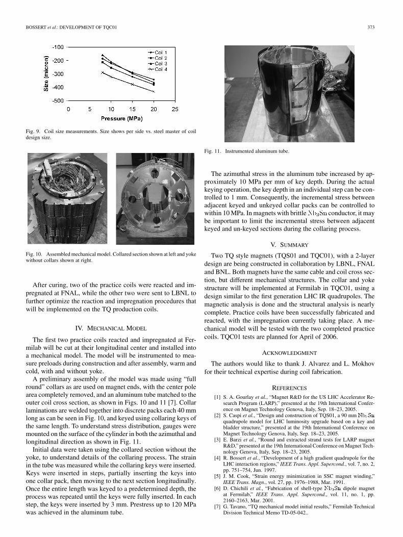
Fig. 9. Coil size measurements. Size shows per side vs. steel master of coildesign size.
Fig. 10. Assembled mechanical model. Collared section shown at left and yokewithout collars shown at right.
After curing, two of the practice coils were reacted and im-pregnated at FNAL, while the other two were sent to LBNL tofurther optimize the reaction and impregnation procedures thatwill be implemented on the TQ production coils.
IV. MECHANICAL MODEL
The first two practice coils reacted and impregnated at Fer-milab will be cut at their longitudinal center and installed intoa mechanical model. The model will be instrumented to mea-sure preloads during construction and after assembly, warm andcold, with and without yoke.
A preliminary assembly of the model was made using “fullround” collars as are used on magnet ends, with the center polearea completely removed, and an aluminum tube matched to theouter coil cross section, as shown in Figs. 10 and 11 [7]. Collarlaminations are welded together into discrete packs each 40 mmlong as can be seen in Fig. 10, and keyed using collaring keys ofthe same length. To understand stress distribution, gauges weremounted on the surface of the cylinder in both the azimuthal andlongitudinal direction as shown in Fig. 11.
Initial data were taken using the collared section without theyoke, to understand details of the collaring process. The strainin the tube was measured while the collaring keys were inserted.Keys were inserted in steps, partially inserting the keys intoone collar pack, then moving to the next section longitudinally.Once the entire length was keyed to a predetermined depth, theprocess was repeated until the keys were fully inserted. In eachstep, the keys were inserted by 3 mm. Prestress up to 120 MPawas achieved in the aluminum tube.
Fig. 11. Instrumented aluminum tube.
The azimuthal stress in the aluminum tube increased by ap-proximately 10 MPa per mm of key depth. During the actualkeying operation, the key depth in an individual step can be con-trolled to 1 mm. Consequently, the incremental stress betweenadjacent keyed and unkeyed collar packs can be controlled towithin 10 MPa. In magnets with brittle conductor, it maybe important to limit the incremental stress between adjacentkeyed and un-keyed sections during the collaring process.
V. SUMMARY
Two TQ style magnets (TQS01 and TQC01), with a 2-layerdesign are being constructed in collaboration by LBNL, FNALand BNL. Both magnets have the same cable and coil cross sec-tion, but different mechanical structures. The collar and yokestructure will be implemented at Fermilab in TQC01, using adesign similar to the first generation LHC IR quadrupoles. Themagnetic analysis is done and the structural analysis is nearlycomplete. Practice coils have been successfully fabricated andreacted, with the impregnation currently taking place. A me-chanical model will be tested with the two completed practicecoils. TQC01 tests are planned for April of 2006.
ACKNOWLEDGMENT
The authors would like to thank J. Alvarez and L. Mokhovfor their technical expertise during coil fabrication.
REFERENCES
[1] S. A. Gourlay et al., “Magnet R&D for the US LHC Accelerator Re-search Program (LARP),” presented at the 19th International Confer-ence on Magnet Technology Genova, Italy, Sep. 18–23, 2005.
[2] S. Caspi et al., “Design and construction of TQS01, a 90 mm Nb Sn
quadrupole model for LHC luminosity upgrade based on a key andbladder structure,” presented at the 19th International Conference onMagnet Technology Genova, Italy, Sep. 18–23, 2005.
[3] E. Barzi et al., “Round and extracted strand tests for LARP magnetR&D,” presented at the 19th International Conference on Magnet Tech-nology Genova, Italy, Sep. 18–23, 2005.
[4] R. Bossert et al., “Development of a high gradient quadrupole for theLHC interaction regions,” IEEE Trans. Appl. Supercond., vol. 7, no. 2,pp. 751–754, Jun. 1997.
[5] J. M. Cook, “Strain energy minimization in SSC magnet winding,”IEEE Trans. Magn., vol. 27, pp. 1976–1988, Mar. 1991.
[6] D. Chichili et al., “Fabrication of shell-type Nb Sn dipole magnetat Fermilab,” IEEE Trans. Appl. Supercond., vol. 11, no. 1, pp.2160–2163, Mar. 2001.
[7] G. Tavano, “TQ mechanical model initial results,” Fermilab TechnicalDivision Technical Memo TD-05-042..