development of the tri-athlete lunar vehicle … of the tri-athlete lunar vehicle prototype matt...
TRANSCRIPT

317
Development of the Tri-ATHLETE Lunar Vehicle Prototype
Matt Heverly*, Jaret Matthews*, Matt Frost* and Chris McQuin*
Abstract
The Tri-ATHLETE vehicle is the second generation of a wheel-on-limb vehicle being developed to support the return of humans to the lunar surface. This paper describes the design, assembly, and test of the Tri-ATHLETE robotic system with a specific emphasis on the limb joint actuators. The design and implementation of the structural components is discussed, and a novel and low cost approach to approximating flight-like cabling is also presented. The paper concludes with a discussion of the “second system effect” and other lessons learned as well as results from a three week long field trial of the vehicle in the Arizona desert.
Introduction In order to establish a continual human presence on the Moon we must develop assisting infrastructure that can carry cargo as well as provide mobility to the astronauts for exploration and the development of a central, but not necessarily fixed, lunar base. The Tri-ATHLETE vehicle system is a new form of two cooperative robotic vehicles that can act individually or physically connect together through a structural pallet to transport and manipulate cargo.
Figure 1. The second generation ATHLETE rover The basis of the ATHLETE (All Terrain Hex Limed Extra Terrestrial Explorer) robot is the wheel-on-limb vehicle concept. This hybrid mobility platform enables the vehicle to traverse at high speeds across benign terrain, as well as enabling walking, by locking the wheels and using them as feet, on extreme terrain. This vehicle architecture also allows for manipulation since the vehicle is stable on three or more wheels. Non-adjacent limbs can be lifted and used to interact with the environment. A tool mechanism at
* Jet Propulsion Laboratory, California Institute of Technology, Pasadena, CA
Proceedings of the 40th Aerospace Mechanisms Symposium, NASA Kennedy Space Center, May 12-14, 2010
NASA/CP-2010-216272
https://ntrs.nasa.gov/search.jsp?R=20100021930 2018-07-01T05:02:33+00:00Z
318
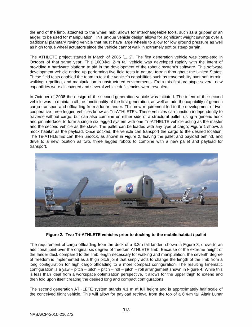
the end of the limb, attached to the wheel hub, allows for interchangeable tools, such as a gripper or an auger, to be used for manipulation. This unique vehicle design allows for significant weight savings over a traditional planetary roving vehicle that must have large wheels to allow for low ground pressure as well as high torque wheel actuators since the vehicle cannot walk in extremely soft or steep terrain. The ATHLETE project started in March of 2005 [1, 2]. The first generation vehicle was completed in October of that same year. This 1000-kg, 2-m tall vehicle was developed rapidly with the intent of providing a hardware platform to aid in the development of the robotic system’s software. This software development vehicle ended up performing five field tests in natural terrain throughout the United States. These field tests enabled the team to test the vehicle’s capabilities such as traversability over soft terrain, walking, repelling, and manipulation in unstructured environments. From this first prototype several new capabilities were discovered and several vehicle deficiencies were revealed. In October of 2008 the design of the second-generation vehicle was initiated. The intent of the second vehicle was to maintain all the functionality of the first generation, as well as add the capability of generic cargo transport and offloading from a lunar lander. This new requirement led to the development of two, cooperative three legged vehicles know as Tri-ATHLETEs. These vehicles can function independently to traverse without cargo, but can also combine on either side of a structural pallet, using a generic hook and pin interface, to form a single six legged system with one Tri-ATHELTE vehicle acting as the master and the second vehicle as the slave. The pallet can be loaded with any type of cargo; Figure 1 shows a mock habitat as the payload. Once docked, the vehicle can transport the cargo to the desired location. The Tri-ATHLETEs can then undock, as shown in Figure 2, leaving the pallet and payload behind, and drive to a new location as two, three legged robots to combine with a new pallet and payload for transport.
Figure 2. Two Tri-ATHLETE vehicles prior to docking to the mobile habitat / pallet The requirement of cargo offloading from the deck of a 3.2m tall lander, shown in Figure 3, drove to an additional joint over the original six degree of freedom ATHLETE limb. Because of the extreme height of the lander deck compared to the limb length necessary for walking and manipulation, the seventh degree of freedom is implemented as a thigh pitch joint that simply acts to change the length of the limb from a long configuration for high cargo offloading to a more compact configuration. The resulting kinematic configuration is a yaw – pitch – pitch – pitch – roll – pitch – roll arrangement shown in Figure 4. While this is less than ideal from a workspace optimization perspective, it allows for the upper thigh to extend and then fold upon itself creating the desired long and compact configurations. The second generation ATHLETE system stands 4.1 m at full height and is approximately half scale of the conceived flight vehicle. This will allow for payload retrieval from the top of a 6.4-m tall Altair Lunar
NASA/CP-2010-216272
319
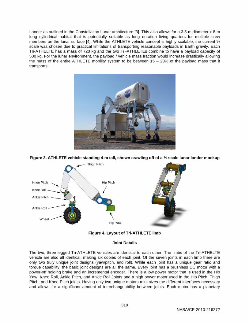
Lander as outlined in the Constellation Lunar architecture [3]. This also allows for a 3.5-m diameter x 8-m long cylindrical habitat that is potentially suitable as long duration living quarters for multiple crew members on the lunar surface [4]. While the ATHLETE vehicle concept is highly scalable, the current ½ scale was chosen due to practical limitations of transporting reasonable payloads in Earth gravity. Each Tri-ATHELTE has a mass of 720 kg and the two Tri-ATHLETEs combine to have a payload capacity of 500 kg. For the lunar environment, the payload / vehicle mass fraction would increase drastically allowing the mass of the entire ATHLETE mobility system to be between 15 – 20% of the payload mass that it transports.
Figure 3. ATHLETE vehicle standing 4-m tall, shown crawling off of a ½ scale lunar lander mockup
Figure 4. Layout of Tri-ATHLETE limb
Joint Details
The two, three legged Tri-ATHLETE vehicles are identical to each other. The limbs of the Tri-ATHELTE vehicle are also all identical, making six copies of each joint. Of the seven joints in each limb there are only two truly unique joint designs (yaw/pitch, and roll). While each joint has a unique gear ratio and torque capability, the basic joint designs are all the same. Every joint has a brushless DC motor with a power-off holding brake and an incremental encoder. There is a low power motor that is used in the Hip Yaw, Knee Roll, Ankle Pitch, and Ankle Roll Joints and a high power motor used in the Hip Pitch, Thigh Pitch, and Knee Pitch joints. Having only two unique motors minimizes the different interfaces necessary and allows for a significant amount of interchangeability between joints. Each motor has a planetary
Hip Pitch
Hip Yaw
Knee Pitch
Knee Roll
Ankle Pitch
Ankle Roll
Wheel
Thigh Pitch
NASA/CP-2010-216272
320
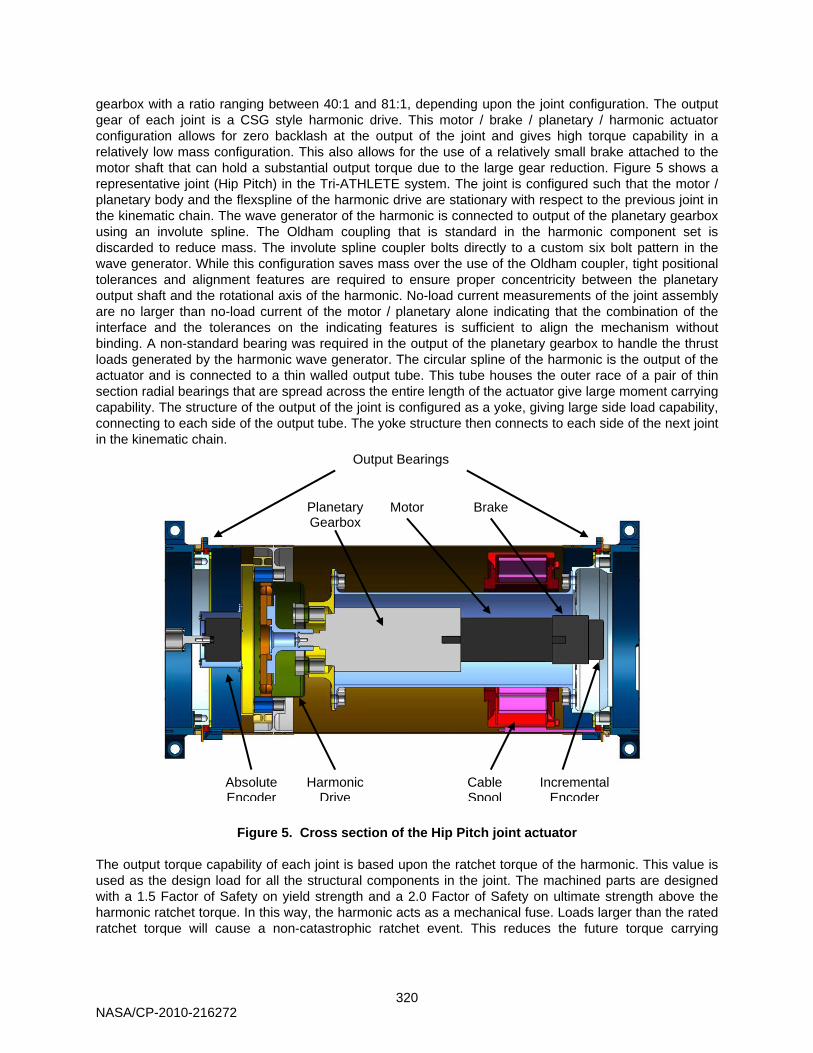
gearbox with a ratio ranging between 40:1 and 81:1, depending upon the joint configuration. The output gear of each joint is a CSG style harmonic drive. This motor / brake / planetary / harmonic actuator configuration allows for zero backlash at the output of the joint and gives high torque capability in a relatively low mass configuration. This also allows for the use of a relatively small brake attached to the motor shaft that can hold a substantial output torque due to the large gear reduction. Figure 5 shows a representative joint (Hip Pitch) in the Tri-ATHLETE system. The joint is configured such that the motor / planetary body and the flexspline of the harmonic drive are stationary with respect to the previous joint in the kinematic chain. The wave generator of the harmonic is connected to output of the planetary gearbox using an involute spline. The Oldham coupling that is standard in the harmonic component set is discarded to reduce mass. The involute spline coupler bolts directly to a custom six bolt pattern in the wave generator. While this configuration saves mass over the use of the Oldham coupler, tight positional tolerances and alignment features are required to ensure proper concentricity between the planetary output shaft and the rotational axis of the harmonic. No-load current measurements of the joint assembly are no larger than no-load current of the motor / planetary alone indicating that the combination of the interface and the tolerances on the indicating features is sufficient to align the mechanism without binding. A non-standard bearing was required in the output of the planetary gearbox to handle the thrust loads generated by the harmonic wave generator. The circular spline of the harmonic is the output of the actuator and is connected to a thin walled output tube. This tube houses the outer race of a pair of thin section radial bearings that are spread across the entire length of the actuator give large moment carrying capability. The structure of the output of the joint is configured as a yoke, giving large side load capability, connecting to each side of the output tube. The yoke structure then connects to each side of the next joint in the kinematic chain.
Figure 5. Cross section of the Hip Pitch joint actuator The output torque capability of each joint is based upon the ratchet torque of the harmonic. This value is used as the design load for all the structural components in the joint. The machined parts are designed with a 1.5 Factor of Safety on yield strength and a 2.0 Factor of Safety on ultimate strength above the harmonic ratchet torque. In this way, the harmonic acts as a mechanical fuse. Loads larger than the rated ratchet torque will cause a non-catastrophic ratchet event. This reduces the future torque carrying
Output Bearings
Planetary Gearbox
Motor Brake
Absolute Encoder
Harmonic Drive
Cable Spool
Incremental Encoder
NASA/CP-2010-216272

321
capability of the joint, but it does not result in complete joint failure. If a structural component were to fail, then an overload event would cause complete loss of the joint instead of simply reduced capability. Table 1 below summarizes the capabilities and overall gear ratios of each of the joints. The speed of each joint is based upon the desire to actively servo the limbs over undulating terrain with slopes up to 10° while keeping the pallet level at the nominal driving speed of the vehicle, 3 kph.
Table 1. Summary of Joint Gear Ratio and Capability
Joint Overall Gear Ratio
Harmonic Drive
Ratchet Torque
No-Load Speed
Hip Yaw 6,591 : 1 CSG-40-80 3.600 Nm 0.16 rad/s Hip Pitch -6,480 : 1 CSG-58-80 10,000 Nm 0.11 rad/s
Thigh Pitch -6,480 : 1 CSG-58-80 10,000 Nm 0.11 rad/s Knee Pitch -3,240 : 1 CSG-40-80 3.600 Nm 0.22 rad/s Knee Roll 3,514 : 1 CSG-32-50 1,200 Nm 0.30 rad/s
Ankle Pitch 6,591 : 1 CSG-32-80 1,800 Nm 0.16 rad/s Ankle Roll 3,514 : 1 CSG-32-50 1,200 Nm 0.30 rad/s
The joint is sealed using a two layer seal. The outer seal is a Nomex felt to protect from large size particles. These felt seals have a rectangular cross section with a height / width aspect ratio between 1.25 and 2.0, where height is measured parallel to the rotation axis. The seal is compressed axially between 7% and 16% of its nominal height and rides on hard anodized aluminum surfaces. This amount of compression provides for good sealing, but contributes to significant drag torque. The highly compressed seals were also forced out of their designed grooves since the hoop strength of the seal is extremely low. Axial compression between 5% - 10% is sufficient for the felt seal design and in practice the seal should be captured or bonded in place to prevent radial expansion of the felt material. The inner seal is a spring loaded Teflon lip seal that also rides on a hard anodized surface. This seal prevents small particles from entering the joint and will remain in contact through thermal expansion and contraction with very little change in lip sealing force due to the radial expanding spring. This same method of double seal has been used successfully in high dust environment missions such as the Mars Exploration Rovers [5].
Joint Sensing and Control
The overall coordination of the joints is done by the main computer, which is housed in the rover body. This computer transmits via point commands to each motor controller over a CAN network bus at 8 Hz. The motor controller is housed locally at each motor and controls the motion of the joint using a position control loop at 2.7 kHz. Joint position via points are updated during motion and are fed from the main CPU to the local controllers. The motor controllers then update the position setpoint and smoothly transition to the new motion profile. Each joint has both an incremental encoder on the motor input as well as a 12-bit absolute encoder on the joint output. The motion of each joint motor is controlled via the incremental encoder, and the limb kinematics is determined from the high precision output encoder. Using these two position sensing devices, the mechanical windup of the joint can be determined. This measurement combined with a characterization of the torsional stiffness of the joint gives the torque experienced at each joint. Using the joint torques and the vehicle’s kinematic pose, the robot can determine the ground contact force of each limb and can autonomously make adjustments to correctly distribute the vehicle load over all the limbs [6].
NASA/CP-2010-216272

322
Structural Details
Most of the Tri-ATHLETE components are made from 7075-T6 aluminum. Due to the large thermal extremes of the lunar environment this material is likely not appropriate for a flight system, but the low cost, low mass, high strength combination led to its use in the prototype vehicle. 7075-T6 is approximately 1.8X as strong as 6061-T6, but can be up to three times the raw material cost. Due to the complexity and machining time of many of the Tri-ATHLETE parts, the use of 7075-T6 added approximately 20-25% to the total cost per part. Given the added strength to weight ratio of 7075-T6 this trade was an economical way to keep the total mass down. To further reduce cost and mass, bonded and rivet joints are used whenever possible. These joints act similar to monolithic parts in their strength and weight characteristics, but without the high cost associated with machining large complicated geometries. The output tubes of all the joints are manufactured with bonded and riveted end fittings as well as a bonded and riveted interface that bolts to the circular spline of the harmonic. Hysol EA 9394 adhesive is used as a liquid shim between concentric features. Radial rivets are then used to join the parts. In analysis, it is assumed that the rivets take the entire load while the adhesive contributes no shear strength, only transmitting compressive load. The body of the rover is made from a similar riveted structure. Custom structural ribs are joined to an aluminum sheet metal skin using a combination of blind as well as solid aluminum rivets. This allows the body, shown in Figure 6, to be a closed box structure, which gives a high strength-to-weight and stiffness-to-weight ratio.
Figure 6. ATHLETE rover chassis, implemented as a riveted box structure
With the exception of the riveted tubes and the riveted body frame, all structural interfaces are implemented using a bolted joint in friction. This allows for interchangeable components without the need for matched and pinned joints. Each structural joint was analyzed using a clamping force equal to the bolt preload multiplied by the number of bolts with an assumed coefficient of friction of 0.2. The bolt preload is based upon the minimum load of either the bolt or the internal threads. For the bolt, the maximum load is 50% of the fastener ultimate tensile strength using the tensile stress area. For the internal threads, if an insert is used, the preload capability is 50% of the pullout load for inserts. If the bolt threads directly into a tapped hole, then the maximum preload is 57% of the load capability of the tapped hole. The application torque is then
T=KPD. (1) where P is the preload, D is the nominal diameter and K is the nut factor which depends on the lubrication and surface finish. The nut factor that was used was based on tension versus torque testing performed at JPL using Solithane applied to the threads. In the ATHLETE vehicle Loctite 243 was used instead of Solithane, but it was considered an equivalent lubricant for fastener installation and a similar fastener staking method once it had cured. For all critical fasteners, 1200 MPa (180 ksi) steel black oxide socket head cap screws were used. For non-structural fasteners, such as external covers, stainless steel fasteners were used. This makes for easy identification of fasteners that require precision assembly with a torque wrench.
NASA/CP-2010-216272
323
Avionics Packaging Each Tri-ATHLETE contains an identical set of avionics, which are packaged in a “drop tray” that can be easily lowered down from the main rover chassis shown in Figure 7. Central to the drop tray, and dominating its design considerations, is a set of four Valence Technologies lithium iron magnesium phosphate batteries wired in series. The resulting 78-kg pack has a voltage of 51.2 V and a capacity of 130 Ah. The batteries are capable of providing 300 A max current for 30 seconds. The batteries are charged by a pair of 1 kW / 60 V power supplies whose outputs are toggled by a battery management system (also from Valence) that monitors the battery health and state of charge. The drop tray also houses a 4U cPCI card cage that contains four XCalibur1000 800-MHz PowerPC computers from Extreme Engineering. These computers were chosen because of the existence of a space flight qualified computer with comparable capabilities. One of the four computers is devoted to controlling the rover’s motion and communicating with ground systems while the other three computers are each devoted to stereo vision processing for four of the twelve camera pairs on the rover. Seven of these camera pairs are housed in the drop tray along with a 1-W wireless router and other navigation/attitude control sensors (MEMS IMU, GPS, and high resolution tilt sensor).
Figure 7. Rover avionics, housed in a drop tray that can be lowered from the main chassis With the exception of the leg cabling harness and distributed motor controllers, the drop tray contains nearly all of the rover’s avionics and associated wiring. This proved to be of great convenience and represents a significant advancement over the previous chassis design. The ability to remove the avionics in this monolithic way allowed for easy assembly, maintenance, and repair operations. In addition, the drop tray provided a method for bench top testing all the major systems before they were fully integrated into the rover.
Cabling Design A major innovation in the Tri-ATHLETE vehicle over the original ATHLETE is the implementation of the cable harness. The original vehicle used a round wire harness that was entirely external to the limb. This created several “chopping” points where the cable could be cut by structural links passing over each other. For the second generation of the robot, the cable harness is completely internal to the limb structure. This is implemented using essentially a round wire harness imbedded in a flat silicone extrusion. This technique, developed by Cicoil™, allows for the use of any combination of round wires, packaged in a flexible, flat ribbon arrangement. The harness is routed down along the limb and an
NASA/CP-2010-216272

324
internal cable spool is used to create a clock spring configuration with the cable that allows for the ±180 degree range of motion at each joint. The cable harness is broken in to seven segments, where each segment terminates at the joint motor controller. Multiple cable segments allows for the ability to quickly sever the limb at any joint. This is extremely useful for both debugging and repair. A custom board connects the appropriate power line from the harness to the motor / controller and interfaces the controller to the CAN communications bus that runs down the entire length of the limb. The cable itself consists of a 60V DC power bus, a 12-V DC auxiliary power line, CAN bus, and a CAT6 Ethernet line to transmit video from a camera at the limb end effector. Since the required current for all joint motors can be as large as 100 A, the power bus is implemented using 15 twisted and shielded 22-gauge wire pairs, connected to the main power system in parallel. These power lines are configured such that 5 pairs provide power the upper most actuators in the kinematic chain (Hip Yaw, Hip Pitch, & Thigh Pitch). The next five pairs of the 60-V bus power the actuators in the lower portion of the limb (Knee Pitch, Knee Roll, Ankle Pitch, & Ankle Roll). The last five pairs power the wheel motor, which can consume 30 A continuous and 60 A peak current. In this way, the power axes can be stripped away from the main harness as the cable progresses down the limb, incrementally shrinking the width of the cable. A cross section of the cable harness is shown in Figure 8.
Figure 8. Leg Harness Cross Section
Wheel Design
The Tri-ATHLETE team is also collaborating with Michelin on the development of a non-pneumatic compliant wheel design that is appropriate for the lunar environment. This 71-cm diameter by 23-cm wide wheel is sized to support both the Tri-ATHLETE and NASA JSC Chariot rovers (2500-N nominal load, 4500-N max load, 10-kph top speed) and efficiently carries load by using Michelin Tweel® derived mechanics [7]. One advantage of this approach is that the wheel’s effective contact pressure is largely independent of load and uniform across the ground contact area. A low and uniform ground contact pressure greatly contributes to the overall mobility performance of Tri-ATHLETE. In addition, this wheel design, which contains no elastomers, exhibits low energy loss from obstacle impacts and allows for a tunable vertical stiffness that is independent of contact pressure. These features are important because the wheel system is the only additional source of passive compliance beyond actuator windup and deflection of the major structural members on Tri-ATHLETE. The most recent design iteration, shown in Figure 9, of the so-called Michelin Lunar Wheel is comprised of a proprietary composite that has a specific elastic strength (elastic strength/density) that is 4.7 times that of 7075-T6 aluminum and 7.2 times that of 36NiCrMo16 steel. This material was chosen primarily because of its excellent cryogenic resilience such that the wheel may remain flexible at the lower end of the lunar surface temperature regime (40K, -233.15ºC). Paradoxically the mechanical properties of the
NASA/CP-2010-216272

325
composite (flex fatigue, compression and tensile modulus) improve at cryogenic temperatures. This has enabled JPL and Michelin to demonstrate driving the wheel more than 5000 km under load while being fully immersed in liquid nitrogen. With a mass of only 15 kg, this wheel has a load carrying multiplier (load capability/wheel mass), which is three times that achieved by the original Apollo Lunar Rover wheel.
Figure 9. Michelin Lunar Wheel Impacting a 10-cm Tall Rock
Lessons Learned
The Tri-ATHLETE robot is the second generation of ATHLETE vehicles. The first vehicle was completed in 7 months from concept to fully functional robot. The vehicle was then tested for three years and its shortcomings became evident. In the design of the second generation ATHLETE vehicle, the development team tried to solve all of the problems with the first vehicle and add substantial functionality, which in turn added significant complexity, cost, and schedule over the development of the first vehicle. From the onset of the re-design effort the team was very aware of “the second system effect” but was unable to avoid it [8]. Continually trying to solve every problem led to a significant slip in the schedule and a significant increase in the scope of the project. What started as the re-design of only two joints to increase the load carrying capability of the vehicle, quickly escalated to a complete re-design with significantly more complex end-of-year milestones. In hindsight it would have been easier to break the re-design of the vehicle in to smaller incremental developments so that new innovations could be tested and refined instead of one large re-design effort. Tri-ATHLETE is a research project with a team of four mechanical design engineers. This is a relatively small project, but large enough to necessitate consistent guidelines and requirements across the team. This was implemented using clear load cases, structural margin philosophy, and design procedures. The load case was clearly defined as a two-leg iron cross, which is the vehicle supporting itself on two opposing limbs completely outstretched. This sets the load capabilities of each of the pitch joint actuators and associate structure. Similar pose derived requirements size the necessary capabilities for the yaw and roll joints. The mass of components was reduced to the extent possible while still meeting the functional and structural requirements. A guideline of $1000/kg was used to evaluate the merit of light-weighting features, meaning special machining operations would be employed simply to remove mass from custom designed parts if the incremental cost of that particular machining operation per unit of mass removed was below $1000/kg. Even with a small team, these clear guidelines established at the beginning of the project kept the entire team designing to the same requirements and reduced the amount of time spent debating the proper balance of capability, complexity, and cost. In contrast with the implementation of rigorous structural guidelines, much looser rules were used when designing the cable routing. Schedule allowed for the testing of the cable spool clock springs that were used inside the joints because of rapid prototyped cable trays, but it did not allow for an entire joint to be
NASA/CP-2010-216272

326
assembled before setting the cable segment length. As a result, motor controller mounting locations were only approximated and the true cable path was not defined. At the time of procurement of the cables, the length was only roughly approximated and 45 cm (18 inches) was added to either end of the cable as margin. This ultimately resulted in significantly more cable than was necessary and posed a significant challenge of packaging excess and unplanned cable. If more time were invested initially in the definition and modeling of the cable routing, then less margin for uncertainty would be necessary. While accurately modeling cabling is difficult it ultimately saves significant time and effort in the long run.
Conclusions
In September of 2009, the vehicle was tested for three weeks at the Black Point lava flow near Flagstaff, AZ. This test demonstrated an initial set of capabilities for the vehicle, including demonstrating the offloading of cargo from a 3.2-m tall mock lander, walking over obstacles over 1-m tall, excavating soil using a backhoe tool attachment, and accumulating more than 6km of total traverse distance. This field test also highlighted the shortcomings and exposed some of the complexities of the system. Future refinements will deal with problems of electrical noise in the actuators, power system upgrades, and limited bandwidth from simultaneously commanding and coordinating 48 actuators and 24 cameras on each Tri-ATHLETE vehicle. All of these shortcomings, however, can be overcome and the Tri-ATHLETE system has proven to provide a unique capability of cargo handling and transportation, as well as tool use and payload manipulation that fits well within the current lunar architecture.
Acknowledgements
The authors would like to thank the entire ATHELTE team, the staff of Michelin Recherche et technique S.A. for the design and construction of the Michelin Lunar Wheel, and the NASA Human-Robot Systems (HRS) project, part of the Exploration Technology Development Program (ETDP), for funding this work. The work described in this paper was performed by the Jet Propulsion Laboratory, California Institute of Technology, under contract with the National Aeronautics and Space Administration. Copyright 2009 California Institute of Technology. Government sponsorship acknowledged.
References
1. Wilcox, B.H. “ATHLETE: A Cargo and Habitat Transporter for the Moon”, Proceeding of the 2009 IEEE Aerospace Conference, Big Sky, Montana, USA, March 7-14, 2009.
2. Heverly, M., Matthews, J. "A Wheel-on-limb rover for lunar operation," in Proceedings of the 9th International Symposium on Artificial Intelligence, Robotics and Automation in Space (iSAIRAS), February 25-29, 2008.
3. Carroll, Michael. The Seventh Landing: Going Back to the Moon, This Time to Stay. pg 82 Springer New York. 2009.
4. Toups, L., Kennedy, K.J., et al, “Constellation Architecture Team-Lunar Habitation Concepts”, Proceedings of the AIAA Space 2008 Conference & Exposition, San Diego, California, September 9-11, 2008.
5. Krishnan, S. Voorhees, C., “The use of harmonic drives on NASA's Mars Exploration Rover,” Harmonic Drive International Symposium 2001 Nagano, Japan November 20-21, 2001.
6. Collins, C. “Stiffness Modeling and Force Distribution for the All-Terrain Hex-Limbed Extra-Terrestrial Explorer (ATHLETE)”, Proc. ASME 2007 International Design Engineering Technical Conferences & Computers and Information in Engineering Conference, Las Vegas, Nevada, USA, September 4 – 7, 2007.
7. Rhyne, Timothy B. and Cron, Steven M. “Development of a Non-Pneumatic Wheel,” presented at the 24th Annual Meeting and Conference on Tire Science and Technology, Tire Society, Akron, Ohio, USA. September 20-21, 2005.
8. Brooks, Fred. The Mythical Man Month. Addison-Wesley, 1995
NASA/CP-2010-216272