development of the tandem-x calibration concept:...
TRANSCRIPT
716 IEEE TRANSACTIONS ON GEOSCIENCE AND REMOTE SENSING, VOL. 48, NO. 2, FEBRUARY 2010
Development of the TanDEM-X CalibrationConcept: Analysis of Systematic Errors
Jaime Hueso González, Markus Bachmann, Gerhard Krieger, Member, IEEE, and Hauke Fiedler
Abstract—The TanDEM-X mission, result of the partnershipbetween the German Aerospace Center (DLR) and AstriumGmbH, opens a new era in spaceborne radar remote sensing. Thefirst bistatic satellite synthetic aperture radar mission is formedby flying TanDEM-X and TerraSAR-X in a closely controlledhelix formation. The primary mission goal is the derivation ofa high-precision global digital elevation model (DEM) accordingto High-Resolution Terrain Information (HRTI) level 3 accuracy.The finite precision of the baseline knowledge and uncompensatedradar instrument drifts introduce errors that may compromise theheight accuracy requirements. By means of a DEM calibration,which uses absolute height references, and the information pro-vided by adjacent interferogram overlaps, these height errors canbe minimized. This paper summarizes the exhaustive studies ofthe nature of the residual-error sources that have been carriedout during the development of the DEM calibration concept.Models for these errors are set up and simulations of the resultingDEM height error for different scenarios provide the basis forthe development of a successful DEM calibration strategy for theTanDEM-X mission.
Index Terms—Baseline, digital elevation model (DEM) calibra-tion, interferometry, phase errors, synthetic aperture radar (SAR),TanDEM-X.
I. INTRODUCTION
THE TanDEM-X satellite (TDX) will be launched in thelast quarter of 2009 to join its twin satellite TerraSAR-X
(TSX), in orbit since June 2007, and to form the first bistaticsingle-pass synthetic aperture radar (SAR) satellite formation[1]. The satellites, originally designed for standalone mono-static operations, have been upgraded to be also capable ofperforming bistatic acquisitions, thus enabling the derivation ofDEMs from SAR interferometry (InSAR [2]) during three yearsof combined operations. The TanDEM-X mission [1] representsa new generation of complex spaceborne SAR systems, and ithas the challenge to deliver a global DEM with HRTI-3-likeheight accuracy (Table I and [3]) within four years after launch.
The only comparable project was the Shuttle Radar Topogra-phy Mission (SRTM/X-SAR) [4], which mapped three dimen-sionally 80% of the Earth’s landmass in 2000.
Manuscript received February 27, 2009; revised July 10, 2009,August 24, 2009, and October 8, 2009. First published December 15,2009; current version published January 20, 2010. This work was supportedin part by the German Federal Ministry for Economics and Technology(Förderkennzeichen 50 EE 0601).
The authors are with the Microwaves and Radar Institute, German AerospaceCenter (DLR), 82234 Wessling, Germany (e-mail: [email protected];[email protected]; [email protected]; [email protected]).
Color versions of one or more of the figures in this paper are available onlineat http://ieeexplore.ieee.org.
Digital Object Identifier 10.1109/TGRS.2009.2034980
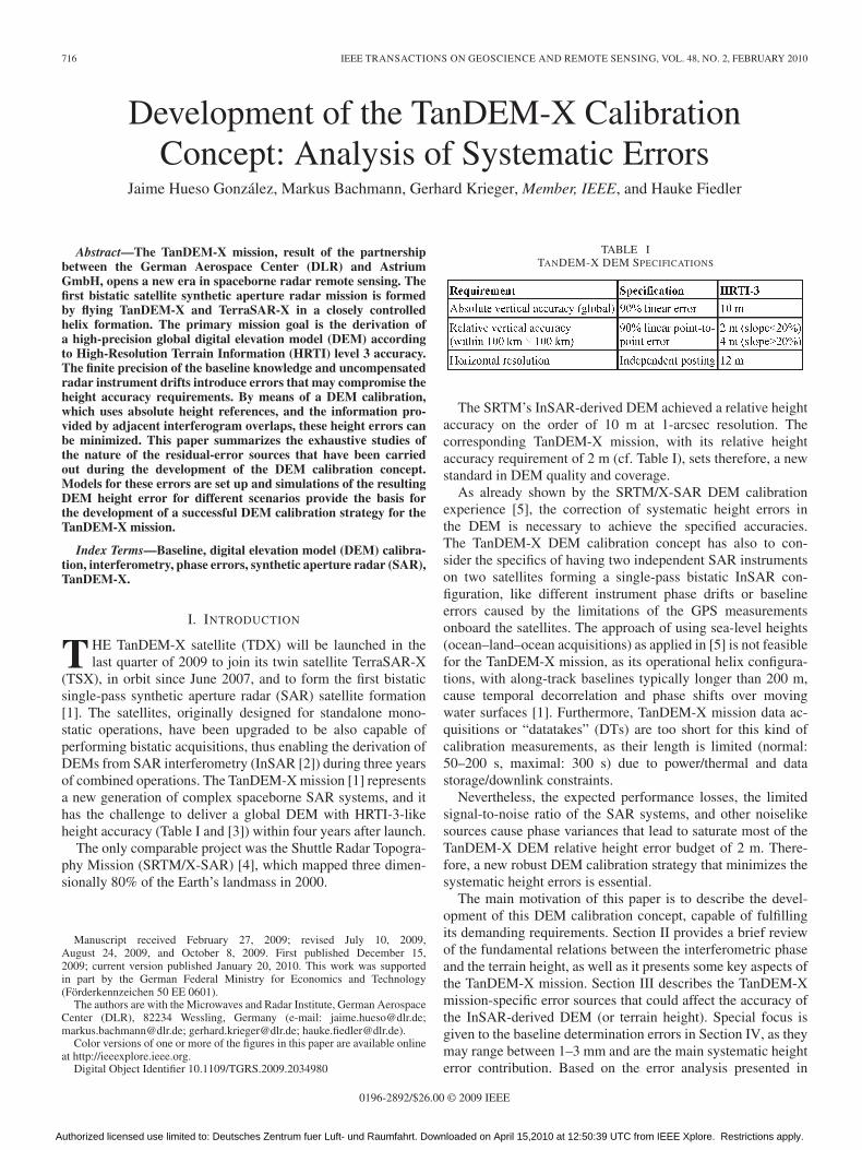
TABLE ITANDEM-X DEM SPECIFICATIONS
The SRTM’s InSAR-derived DEM achieved a relative heightaccuracy on the order of 10 m at 1-arcsec resolution. Thecorresponding TanDEM-X mission, with its relative heightaccuracy requirement of 2 m (cf. Table I), sets therefore, a newstandard in DEM quality and coverage.
As already shown by the SRTM/X-SAR DEM calibrationexperience [5], the correction of systematic height errors inthe DEM is necessary to achieve the specified accuracies.The TanDEM-X DEM calibration concept has also to con-sider the specifics of having two independent SAR instrumentson two satellites forming a single-pass bistatic InSAR con-figuration, like different instrument phase drifts or baselineerrors caused by the limitations of the GPS measurementsonboard the satellites. The approach of using sea-level heights(ocean–land–ocean acquisitions) as applied in [5] is not feasiblefor the TanDEM-X mission, as its operational helix configura-tions, with along-track baselines typically longer than 200 m,cause temporal decorrelation and phase shifts over movingwater surfaces [1]. Furthermore, TanDEM-X mission data ac-quisitions or “datatakes” (DTs) are too short for this kind ofcalibration measurements, as their length is limited (normal:50–200 s, maximal: 300 s) due to power/thermal and datastorage/downlink constraints.
Nevertheless, the expected performance losses, the limitedsignal-to-noise ratio of the SAR systems, and other noiselikesources cause phase variances that lead to saturate most of theTanDEM-X DEM relative height error budget of 2 m. There-fore, a new robust DEM calibration strategy that minimizes thesystematic height errors is essential.
The main motivation of this paper is to describe the devel-opment of this DEM calibration concept, capable of fulfillingits demanding requirements. Section II provides a brief reviewof the fundamental relations between the interferometric phaseand the terrain height, as well as it presents some key aspects ofthe TanDEM-X mission. Section III describes the TanDEM-Xmission-specific error sources that could affect the accuracy ofthe InSAR-derived DEM (or terrain height). Special focus isgiven to the baseline determination errors in Section IV, as theymay range between 1–3 mm and are the main systematic heighterror contribution. Based on the error analysis presented in
0196-2892/$26.00 © 2009 IEEE
Authorized licensed use limited to: Deutsches Zentrum fuer Luft- und Raumfahrt. Downloaded on April 15,2010 at 12:50:39 UTC from IEEE Xplore. Restrictions apply.

HUESO GONZÁLEZ et al.: DEVELOPMENT OF THE TANDEM-X CALIBRATION CONCEPT 717
Fig. 1. SAR interferometry imaging geometry for the TanDEM-X mission.
Sections III and IV, a suitable correction model is derived,which is discussed in Section V along with some simulationresults. The paper concludes in Section VI with some consid-erations about the expected quality of the final TanDEM-Xglobal DEM.
II. INSAR AND TANDEM-X FUNDAMENTALS
A. TanDEM-X Interferometric Phase and Height Errors
The SAR interferometry imaging geometry for theTanDEM-X mission is shown in Fig. 1.
Bistatic interferometric SAR data acquisitions for DEM gen-eration consist of one satellite transmitting radar pulses (active),while both satellites receive simultaneously the radar echoesfrom the ground. The satellite in receive-only mode is thepassive satellite. The interferogram is computed from the phasedifference between the complex monostatic and bistatic SARimages. In TanDEM-X mission DTs, either TSX or TDX can beselected as the active satellite depending on the relative positionbetween them (one satellite should not directly illuminate theother one) and on power-consumption considerations.
The relative position or baseline B is defined as the vectorthat links the two SAR antenna phase centers. Assuming zeroalong-track displacement and following the notation of Fig. 1,the main relation between the bistatic interferometric phase andB is [2]
φ ≈ −2π
λ〈r̂, �B〉 (1)
where λ is the SAR signal wavelength and r̂ is the slant rangeunitary vector from the emitting satellite to the ground target.The approximation in (1) is justified by the fact that |B| � |r|.
Fig. 1 also shows the decompositions of the baseline vectorB‖ and B⊥. B‖ is the projection of B parallel to the line-of-sight (LOS) direction, whereas B⊥ (also called effective base-line) is the corresponding projection perpendicular to the LOS.Subtracting from the interferometric phase, the contribution ofthe flat Earth, the remaining phase history represents the heightchanges over the Earth surface.
The height of ambiguity hamb is a key InSAR performanceparameter providing the information on the terrain height that
can be unambiguously resolved within the 2π definition rangeof the interferometric phase
hamb =λr sin(θi)
B⊥(2)
where θi is the incidence angle. This equation points out thatB⊥ controls the phase-to-height conversion and determines theheight resolution of the system.
Instrument phase drifts and noise contributions affect thequality of the interferogram in the following way [1], [6].
1) They cause height errors, as can be directly derived from(1) and (2)
herr =hamb
2π· φerr. (3)
Baseline errors have different impacts depending ontheir orientation with respect to the SAR LOS [1], [6].
2) Along-track baseline errors are resolved during process-ing and are therefore uncritical.
3) Baseline errors perpendicular to the LOS (B⊥err) causea bias in the phase-to-height scaling, which, in theTanDEM-X mission, practically results in errors on theorder of few centimeters.
4) Baseline errors parallel to the LOS (B‖err) cause a verti-cal displacement of the DEM
herr =hamb
λ· B‖err. (4)
As hamb varies with θi, the vertical displacement causes a tiltin the ground range of the DEM given by
ϕtilt =herr
Δs=
B‖errB⊥
(5)
where Δs is the ground range distance from a selected referencepoint.
The hamb of the system is constantly changing during flight(e.g., from 39 to 41 m for a typical M-C1 mission phase [1]and normal DT length), as the baseline follows a cyclical helixconfiguration (like Fig. 2). As height errors motivated bothby baseline and phase errors are dependent on hamb, theirtemporal evolution is modified with the changes of the baselineconfiguration and the incidence angle.
This implies a small change of the height error in azimuthin any acquired interferometric DT, even if the baseline errorwould be constant. This effect introduces certain nonlinearitiesin the phase-to-height conversion of the errors, which compli-cates the design of DEM correction functions.
B. Mission and Acquisition Plan
A fine adjustment of the orbit parameters of both satellites(horizontal orbital displacement by different ascending nodeswith a vertical separation by different eccentricity vectors)results in a closely controlled helix formation with typicalcrosstrack baselines between 250 and 500 m (Fig. 2 and [1]).
Authorized licensed use limited to: Deutsches Zentrum fuer Luft- und Raumfahrt. Downloaded on April 15,2010 at 12:50:39 UTC from IEEE Xplore. Restrictions apply.
718 IEEE TRANSACTIONS ON GEOSCIENCE AND REMOTE SENSING, VOL. 48, NO. 2, FEBRUARY 2010
The parameters of the helix configuration are modified dur-ing the mission in order to enable an interferometric mappingof the complete Earth surface with a stable hamb.
The best conditions for interferometric SAR image acqui-sitions with respect to DEM generation are the orbit instantswith maximal effective baseline (black arrows in Fig. 2), andtherefore, minimal and slowly changing hamb. As a resultof this strategy, the Northern Hemisphere will be mapped atleast twice with scaled baselines using ascending orbits and,analogously, the Southern Hemisphere with descending orbits.
C. DEM Processing and Calibration
The DEM-generation chain of the TanDEM-X system istriggered when the baseline product, based on GPS navigationdata recorded by both satellites, is available.
The first stage, the interferometric TanDEM-X processor(ITP), derives the SAR images, georeferences them, and cal-culates the raw DEMs. The georeferencing is supported bythe external calibration of the SAR system, which takes placeduring the satellite-commissioning phase. The ITP implementsmultibaseline phase-unwrapping algorithms [7] and techniqueslike the delta-k interferometry [8] in order to minimize phase-unwrapping errors. It is foreseen to acquire data sets overdifficult terrain (like mountainous areas) with three or moredifferent effective baselines to improve the robustness of themethod.
Moreover, within the ITP, other corrections take place, likethe compensation of the SAR antenna phase patterns and thecorrection of the SAR instrument phase drifts by applying theinternal calibration replicas. As each satellite has its own localoscillator, relative phase drifts are monitored via a dedicatedsynchronization link, through which special sync pulses areperiodically exchanged between the twin satellites during aTanDEM-X mission DT. The sync pulses are stored in thesame way as imaging pulses and are then evaluated on groundby the ITP to derive a compensation phase to apply to theinterferogram.
However, the corrected raw DEMs from the ITP may stillcontain residual height errors. The DEM calibration concept isthe strategy to compensate them. The concept is implementedby the Mosaicking and Calibration Processor (MCP) [9], whichis in charge of delivering the final TanDEM-X global DEM atthe end of the mission, once all raw DEMs are available. TheDEM calibration concept also defines the selection of suitableheight references and gives inputs to the data acquisition plan.
III. RESIDUAL-ERROR SOURCES
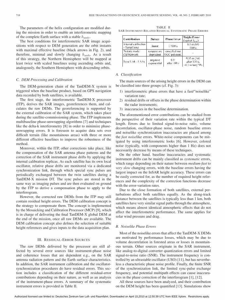
The raw DEMs delivered by the processor are still af-fected by several error sources like instrument-phase noiseand coherence losses that are dependent e.g., on the SARantenna radiation pattern and the Earth surface characteristics.In addition, the SAR instrument calibration and the oscillator-synchronization procedures do have residual errors. This sec-tion includes a classification of the different residual-errorcontributions depending on their nature, as well as an analysisof the instrument-phase errors. A summary of the systematicinstrument errors is provided in Table II.
TABLE IISAR INSTRUMENT-RELATED RESIDUAL SYSTEMATIC PHASE ERRORS
A. Classification
The main sources of the arising height errors in the DEM canbe classified into three groups (cf. Fig. 3):
1) interferometric phase errors that have a fast/“noiselike”variation rate;
2) residual drifts or offsets in the phase determination withinthe radar instruments;
3) inaccuracies in the baseline determination.
The aforementioned error contributions can be studied fromthe perspective of their variation rate within the typical DTlength. Errors due to limited signal-to-noise ratio, volumedecorrelation, oscillator-phase noise, random baseline errorsand noiselike synchronization inaccuracies are placed amongthe fast noiselike errors. White-noise components can be mit-igated by using interferometric looks [6]. However, colorednoise (typically, with components higher than 1 Hz) does notnecessarily decrease by means of these techniques.
On the other hand, baseline inaccuracies and systematicinstrument drifts can be mainly classified as systematic errors,which range depending on their nature between medium-fast tovery slow changing errors, with the baseline errors having thelargest impact on the InSAR height accuracy. These errors canbe easily corrected for, as the number of required height refer-ences and the complexity of the correction functions decreasewith the error-variation rates.
Due to the close formation of both satellites, external per-turbations affect both satellites equally. As the along-trackdistance between the satellites is typically less than 1 km, bothsatellites have very similar signal paths through the atmosphere,which means almost identical atmospheric effects that do notaffect the interferometric performance. The same applies forsolar wind pressure and drag.
B. Noiselike Phase Errors
Most of the noiselike errors that affect the TanDEM-X DEMsare motivated by performance losses, which may be due tovolume decorrelation in forested areas or losses in mountain-ous terrain. Other sources originate in the SAR instrument,like analog-to-digital converter quantization errors and limitedsignal-to-noise ratio (SNR). The instrument frequency is con-trolled by an ultrastable oscillator (USO) [11], but has neverthe-less a characteristic phase noise profile. Finally, the finite SNRof the synchronization link, the limited sync-pulse exchangefrequency, and potential multipath effects can cause inaccura-cies in the phase correction of the interferogram [1], [12].
All these sources have been analyzed, and their contributionon the DEM height has been quantified [13]. Simulations show
Authorized licensed use limited to: Deutsches Zentrum fuer Luft- und Raumfahrt. Downloaded on April 15,2010 at 12:50:39 UTC from IEEE Xplore. Restrictions apply.

HUESO GONZÁLEZ et al.: DEVELOPMENT OF THE TANDEM-X CALIBRATION CONCEPT 719
Fig. 2. TanDEM-X mission helix formation and baselines over one orbit.
Fig. 3. Nature and impact of systematic and noiselike errors on the DEM.Normal DT duration of 50–200 s assumed.
that, for worst case scenarios, the height error due to the overallnoiselike error components is around 1.8 m (90% confidencelevel) after interferometric multilooking [13]. This leaves littlemargin for accommodating other error contributions, as thespecification for the total relative height error budget is 2 m(90%). Specifically, it means that the remaining margin forsystematic error correction is 0.53 m (1σ). This is the accuracygoal for the DEM calibration.
C. Residual Instrument Phase Drifts
1) Signal Paths in the SAR Instrument: The radar pulses’phase evolution due to propagation within each SAR instrumentdoes not remain constant over time. Phase distortions occur
Fig. 4. Residual internal calibration error.
on the transmit and receive paths due to temperature effectsnot only mainly in the amplifiers and transmit/receive modules(TRMs) but also in passive devices like power dividers andtransmission lines. These effects are monitored with the internalcalibration loop and compensated during processing. Differen-tial phase drifts between both satellites, as both instrumentshave independent USOs and temperature profiles over time, arecovered by the synchronization link.
2) Internal Calibration: The internal calibration is suitedfor correcting slow phase and amplitude drifts of the instru-ment. The Temperature Compensation Mode (TempComp) [16]is a temperature control strategy during satellite operationsthat automatically measures and adjusts the TRM amplifiersof the antenna electronics in order to stabilize the workingpoint of the instrument under temperature variations. One ofthe consequences of using this mode is that a simple linearinterpolation can be applied to correct for the instrument driftalong a DT (cf. Fig. 4). The remaining errors can be describedwith a systematic linear component, with typical slopes of lessthan 1◦ after 100 s and a random component of 0.15◦ (1σ).
This results in a systematic height error component of lessthan 0.1 m (1σ) for typical height of ambiguities. In the absenceof an internal calibration mechanism, the TempComp modewould still keep the instrument relatively stable ∼5◦ (1σ),causing height errors of around 0.5 m.
3) Bistatic Internal Calibration Approach: The calibrationnetwork of the instrument does not have an effect on the radarpulses, but it modifies the calibration pulses that are used togenerate the replica of the chirp signal, which is applied to com-pensate the instrument behavior in the internal calibration [16].Therefore, changes in temperature that perturb the amplitudeand phase behavior of the calibration loop introduce errors inthe internal calibration and could have a direct effect on theinterferometric accuracy of the system. However, the elementsof the calibration chain, which are mainly passive components,have been properly characterized on the ground by means ofsimple polynomial functions (cf. Fig. 5).
For the TerraSAR-X mission regular stand-alone image ac-quisition mode, a single amplitude correction value is appliedto each DT to compensate the calibration-loop effect. TheseTerraSAR-X mission acquisitions are usually shorter (around15 s) than the ones planned for the interferometric SAR im-age acquisition (50–200 s) during the TanDEM-X mission.
Authorized licensed use limited to: Deutsches Zentrum fuer Luft- und Raumfahrt. Downloaded on April 15,2010 at 12:50:39 UTC from IEEE Xplore. Restrictions apply.

720 IEEE TRANSACTIONS ON GEOSCIENCE AND REMOTE SENSING, VOL. 48, NO. 2, FEBRUARY 2010
Fig. 5. Example for the phase behavior of the TSX Panel Calibration Net-work. Black arrow shows typical increment of temperature in TanDEM-X DTs.Source: Astrium Friedrichshafen.
Therefore, the phase effect of the calibration loop is neglectedfor TerraSAR-X mission DTs.
For the Tan-DEM-X mission, the approach is different: poly-nomials for both amplitude and phase are used to compensatethe effect of temperature changes on the calibration loop. Theorder of the polynomials is typically five or less. However, insome cases, two polynomials are required to cover the entiretemperature range between −10 ◦C and +50 ◦C.
As an extreme example, Fig. 5 shows the phase behavior of acritical element of the calibration network. Typical temperaturechanges in DTs up to 200 s are close to 10 ◦C (the calibrationnetwork does not heat up as much as the front end, as ithas no active element). In extreme cases, this would implyrelatively fast-changing phase errors of around 2.5◦, resulting ina relative DEM height error of about 0.25 m. This height erroris not dramatic, but its fast-changing nature would complicateits correction in the DEM calibration. It has to be noted thatall experiments performed with the TSX satellite to simulateTanDEM-X mission-like DTs have shown smaller calibrationnetwork phase errors than the aforementioned. This is due tothe fact that the contributions of the different elements of thenetwork tend to slightly compensate each other when consid-ering the total phase effect over temperature. As a conservativestrategy, every time a calibration pulse sequence is generated,the correction polynomials are applied, canceling out this typeof instrument-phase errors.
4) Synchronization Link: The exchange of special synchro-nization pulses between the satellites provides coherence tothe bistatic system, but there are some residual drifts re-maining. When processing the phase difference, all reciprocalcomponents cancel out, and only nonreciprocal components,like amplifiers, produce a residual phase error. As the loopis not covered by the internal calibration correction, tempera-ture drifts in the leaf amplifiers (LAAs) have to be correctedfor. This is done using the housekeeping (HK) data from thetemperature sensors on these amplifiers. These sensors have afinite accuracy and resolution. On ground, the temperature HKdata are compared with the LAAs characterization curves andtransformed into phase curves. The rough quantization of thetemperature samples causes the obtained phase curves to differ
Fig. 6. Example LAA phase evolution, obtained from the internal transmis-sion, reception, and central electronic calibration pulses, and faulty sampling.
Fig. 7. Scheme of the location of the navigation and attitude determinationcomponents in the TSX and TDX payload. Cross section of the satellite.
from the real phase drifts, as shown in the comparison of Fig. 6based on TSX measurements before launch.
Assuming a realistic temperature gradient of 7 ◦C over aDT of maximal length (300 s), it corresponds to about 7◦
phase drift, and the phase estimate is faulty by about ±0.5◦,as exemplarily shown in the “resulting error” curve of Fig. 6.The phase error is modeled as a negative exponential functionthat grows to a value of 0.5◦ (1σ) in the first 100 s. The analysisof Fig. 6 shows a mean height error of less than 0.3 m (1σ) forthe whole DT length.
IV. BASELINE DETERMINATION ERRORS
The generation of accurate InSAR-derived DEMs requires aprecise knowledge of the satellite baseline. In the case of theTanDEM-X mission, the accuracy requirement for the baselinedetermination has been set to 1 mm in order to minimize therelative height error.
The baseline determination depends principally on the esti-mation of three parameters, which are the relative satellite orbitposition measured with GPS, the spacecraft attitude determinedwith Star Trackers and the location of the SAR antenna phasecenter (Fig. 7 shows the distribution of these devices on thesatellite payload).
Authorized licensed use limited to: Deutsches Zentrum fuer Luft- und Raumfahrt. Downloaded on April 15,2010 at 12:50:39 UTC from IEEE Xplore. Restrictions apply.

HUESO GONZÁLEZ et al.: DEVELOPMENT OF THE TANDEM-X CALIBRATION CONCEPT 721
A. Attitude Determination
The Star Trackers onboard TSX and TDX are three accuratedigital cameras that use a star map to determine their actualposition and orientation in space. Due to disturbances like sunor moon light incidence, distortions of the optics, etc., theattitude determination accuracy has a slowly varying bias of±0.005◦ in the yaw, pitch, and roll components plus a 0.003◦
sigma random error. A satellite rotation mainly affects theperpendicular baseline in the acquisition geometry and onlyslightly the parallel one. The resulting bias transforms to abaseline LOS error of less than 0.1 mm, which has almost noimpact on the DEM and, therefore, can be neglected.
B. SAR Antenna Phase Center
The phase center of the SAR antenna describes the variationor displacement of the phase curve within the coverage regionagainst a defined origin, here the origin of the antenna coordi-nate system. This phase curve depends on the look angle andhence, is different for each beam. The antenna phase patternshave been measured on the ground with an accuracy of betterthan 3◦ in phase. This deviation from the real pattern remainsrelatively constant over time. The characterized phase curvesare applied during processing to compensate the phase patternsin the SAR images. As the antennas and, particularly, theirwaveguides are manufactured with identical processes for bothsatellites, and the same beams have to be commanded forboth SAR antennas during single-pass bistatic acquisitions, thepotential SAR phase center deviations should equally affectthe mono- and the bistatic path. Therefore, their influence inthe actual baseline is supposed to cancel out, not affecting theDEM quality.
C. GPS Position Measurements
The orbit position is computed by the onboard GPS nav-igation receivers, called Tracking Occultation and Ranging/Integrated GPS Occultation Receiver (TOR/IGOR) system.The verification on TSX proved that an absolute accuracy of5 cm (1σ) is achieved with the TOR/IGOR system fulfilling therequirements.
This accuracy is more than sufficient for the absolute-positioning accuracy. An error in the absolute position trans-forms directly into a height or position error of the measuredtarget point. It would introduce a relatively constant height erroron the order of 5 cm, thus, only affecting the absolute heightaccuracy requirement of 10 m.
It is possible, however, to track the relative changes betweenboth satellites (baseline) with a much higher accuracy. Thisis performed through processing the navigation informationderived from double differential GPS (DDGPS) carrier phasemeasurements between both satellites [14] and applying aKalman-filter method to the data. The use of the differentialinformation even eliminates ionospheric errors and other char-acteristic GPS perturbations. To further improve the baselinedetermination accuracy, the exact GPS antenna phase center,which changes with the GPS-signal incidence angle, has beencharacterized. The effect is then corrected for when generatingthe baseline product.
Fig. 8. One-day comparison between Ka and DDGPS baselines by GRACE.Orbit period ∼90 min. Standard deviation of the error is 0.71 mm < 1 mm.Source: Wermuth/Montenbruck (GSOC-DLR).
The resulting baseline determination accuracy is expected tobe on the order of millimeters. This assumption is based onthe performance of the DDGPS method in similar missionslike GRACE [15]. The comparison is possible as GRACE isalso a two-satellite constellation with similar orbit period, GPSreceivers, and baseline determination methods (DDGPS relativenavigation) as the TanDEM-X constellation. The baseline errorin the GRACE formation was estimated by comparing the GPS-processed data with the highly accurate measurements from adedicated onboard Ka-band link. Fig. 8 shows that the errorcan be modeled by a low-frequency stochastic process thathas a dominant periodical component at around one orbitalrevolution. The amplitude of the error is of less than 1 mm (1σ).
This means that the main component of the baseline erroris changing “slowly” over time compared with the TanDEM-Xmission maximal DT length. The results in TanDEM-X couldbe even better than in GRACE as the baseline length ismuch shorter and the GPS receivers have a slightly betterperformance. This agrees with the baseline accuracy-missionrequirements of 1 mm. Nevertheless, the GPS baseline solutionaccuracy is the main error source for the baseline determination.All other error sources described in Section IV are muchsmaller.
D. Baseline Bias and Its Characterization
Concerning the baseline determination accuracy, it is nec-essary to point out that the GRACE results do not prove thatthe 1-mm baseline accuracy is reached in absolute terms. TheTanDEM-X DEM calibration has a cautious approach andconsiders the possibility of having a small offset in the baselineproduct on the order of 1 to 9 mm. Such an offset could bedue to small measurement errors in the location of the baseline-reference points in the satellite payload, or small systematicerrors of the DDGPS measurements, or other unknown reasons,although the experience in GRACE suggests that it should bealmost constant over time (cf. Fig. 9).
An obvious indication for a baseline bias is a significantabsolute height error of several meters in the raw DEM, whichmay range from three to tenths of meters depending on themagnitude of the bias and the hamb. As it has a constant nature,it can be easily corrected for with absolute height references,but there are other side effects.
Up to now, only the effect of baseline and phase errors onthe height has been described. In fact, phase and baseline errorsparallel to the LOS cause a rotation of the DEM around theflight trajectory, so the height error is always linked to a groundrange displacement grerr (cf. Fig. 10 and [6]). However, itsvalue is small (< 4 m for typical incidence angles and hamb)
Authorized licensed use limited to: Deutsches Zentrum fuer Luft- und Raumfahrt. Downloaded on April 15,2010 at 12:50:39 UTC from IEEE Xplore. Restrictions apply.
722 IEEE TRANSACTIONS ON GEOSCIENCE AND REMOTE SENSING, VOL. 48, NO. 2, FEBRUARY 2010
and negligible for the TanDEM-X mission requirements if thebaseline offset is below 2 mm.
The eventual presence of a bias on the order of several mil-limeters in the baseline product invalidates this approximation.
The posting of the TanDEM-X raw DEMs is 6 and 12 min the final product, respectively. Ground range displacementshave to be considered if their value is on the order of the rawDEM posting or higher, as the DEM might be shifted by one ormore pixels. If two adjacent DTs have ground range displace-ments in opposite directions, the heights in the overlappingregions are compared in different locations, which can causeconsiderable height errors, particularly in mountainous regions.
As shown in (4), the main contribution to the height erroris caused by the baseline error in LOS. In the presence of abaseline bias in LOS larger than 2 mm, it is justified to assumethat this is the only significant source of the systematic heighterror in a DEM.
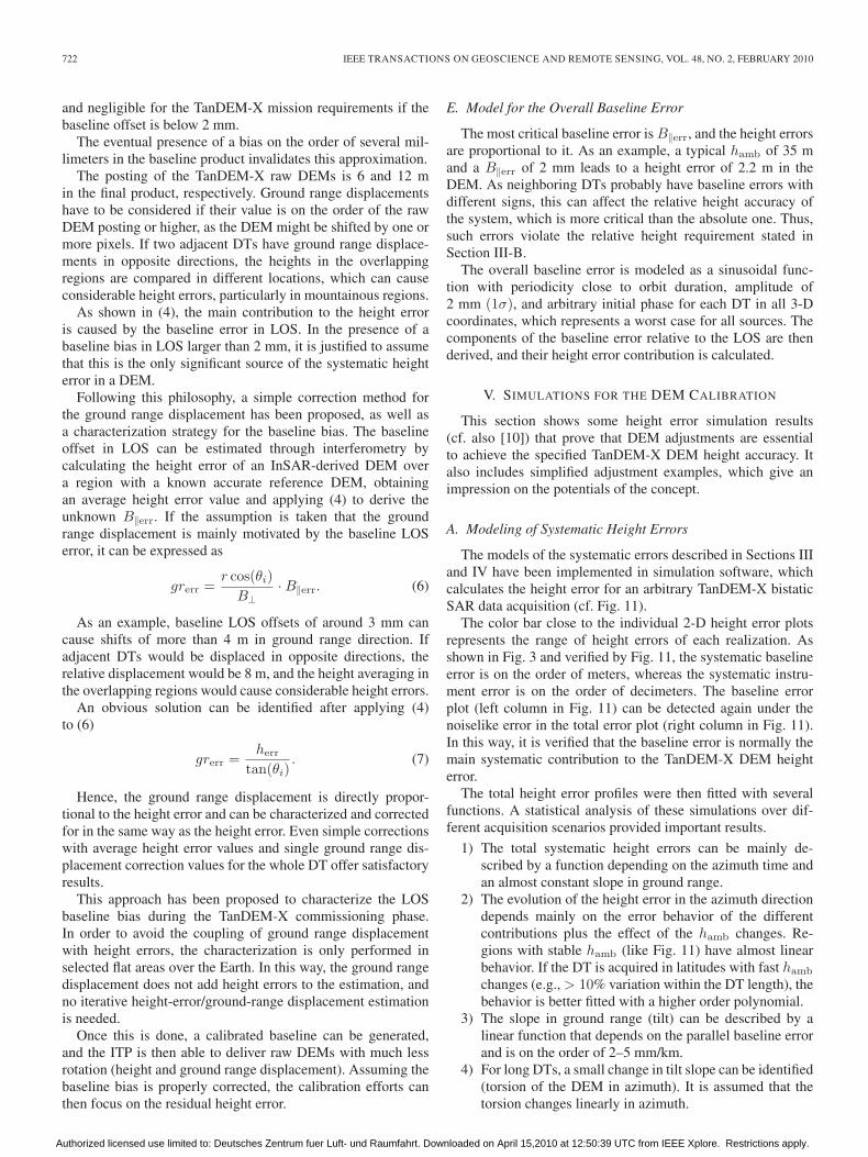
Following this philosophy, a simple correction method forthe ground range displacement has been proposed, as well asa characterization strategy for the baseline bias. The baselineoffset in LOS can be estimated through interferometry bycalculating the height error of an InSAR-derived DEM overa region with a known accurate reference DEM, obtainingan average height error value and applying (4) to derive theunknown B‖err. If the assumption is taken that the groundrange displacement is mainly motivated by the baseline LOSerror, it can be expressed as
grerr =r cos(θi)
B⊥· B‖err. (6)
As an example, baseline LOS offsets of around 3 mm cancause shifts of more than 4 m in ground range direction. Ifadjacent DTs would be displaced in opposite directions, therelative displacement would be 8 m, and the height averaging inthe overlapping regions would cause considerable height errors.
An obvious solution can be identified after applying (4)to (6)
grerr =herr
tan(θi). (7)
Hence, the ground range displacement is directly propor-tional to the height error and can be characterized and correctedfor in the same way as the height error. Even simple correctionswith average height error values and single ground range dis-placement correction values for the whole DT offer satisfactoryresults.
This approach has been proposed to characterize the LOSbaseline bias during the TanDEM-X commissioning phase.In order to avoid the coupling of ground range displacementwith height errors, the characterization is only performed inselected flat areas over the Earth. In this way, the ground rangedisplacement does not add height errors to the estimation, andno iterative height-error/ground-range displacement estimationis needed.
Once this is done, a calibrated baseline can be generated,and the ITP is then able to deliver raw DEMs with much lessrotation (height and ground range displacement). Assuming thebaseline bias is properly corrected, the calibration efforts canthen focus on the residual height error.
E. Model for the Overall Baseline Error
The most critical baseline error is B‖err, and the height errorsare proportional to it. As an example, a typical hamb of 35 mand a B‖err of 2 mm leads to a height error of 2.2 m in theDEM. As neighboring DTs probably have baseline errors withdifferent signs, this can affect the relative height accuracy ofthe system, which is more critical than the absolute one. Thus,such errors violate the relative height requirement stated inSection III-B.
The overall baseline error is modeled as a sinusoidal func-tion with periodicity close to orbit duration, amplitude of2 mm (1σ), and arbitrary initial phase for each DT in all 3-Dcoordinates, which represents a worst case for all sources. Thecomponents of the baseline error relative to the LOS are thenderived, and their height error contribution is calculated.
V. SIMULATIONS FOR THE DEM CALIBRATION
This section shows some height error simulation results(cf. also [10]) that prove that DEM adjustments are essentialto achieve the specified TanDEM-X DEM height accuracy. Italso includes simplified adjustment examples, which give animpression on the potentials of the concept.
A. Modeling of Systematic Height Errors
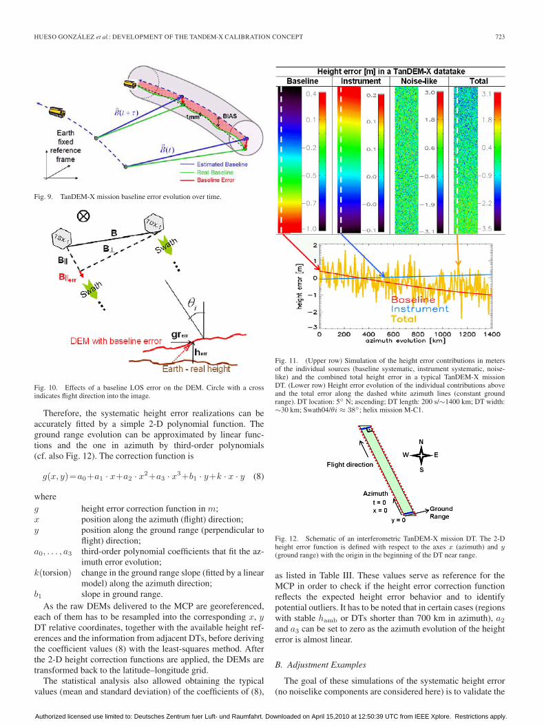
The models of the systematic errors described in Sections IIIand IV have been implemented in simulation software, whichcalculates the height error for an arbitrary TanDEM-X bistaticSAR data acquisition (cf. Fig. 11).
The color bar close to the individual 2-D height error plotsrepresents the range of height errors of each realization. Asshown in Fig. 3 and verified by Fig. 11, the systematic baselineerror is on the order of meters, whereas the systematic instru-ment error is on the order of decimeters. The baseline errorplot (left column in Fig. 11) can be detected again under thenoiselike error in the total error plot (right column in Fig. 11).In this way, it is verified that the baseline error is normally themain systematic contribution to the TanDEM-X DEM heighterror.
The total height error profiles were then fitted with severalfunctions. A statistical analysis of these simulations over dif-ferent acquisition scenarios provided important results.
1) The total systematic height errors can be mainly de-scribed by a function depending on the azimuth time andan almost constant slope in ground range.
2) The evolution of the height error in the azimuth directiondepends mainly on the error behavior of the differentcontributions plus the effect of the hamb changes. Re-gions with stable hamb (like Fig. 11) have almost linearbehavior. If the DT is acquired in latitudes with fast hamb
changes (e.g., > 10% variation within the DT length), thebehavior is better fitted with a higher order polynomial.
3) The slope in ground range (tilt) can be described by alinear function that depends on the parallel baseline errorand is on the order of 2–5 mm/km.
4) For long DTs, a small change in tilt slope can be identified(torsion of the DEM in azimuth). It is assumed that thetorsion changes linearly in azimuth.
Authorized licensed use limited to: Deutsches Zentrum fuer Luft- und Raumfahrt. Downloaded on April 15,2010 at 12:50:39 UTC from IEEE Xplore. Restrictions apply.
HUESO GONZÁLEZ et al.: DEVELOPMENT OF THE TANDEM-X CALIBRATION CONCEPT 723
Fig. 9. TanDEM-X mission baseline error evolution over time.
Fig. 10. Effects of a baseline LOS error on the DEM. Circle with a crossindicates flight direction into the image.
Therefore, the systematic height error realizations can beaccurately fitted by a simple 2-D polynomial function. Theground range evolution can be approximated by linear func-tions and the one in azimuth by third-order polynomials(cf. also Fig. 12). The correction function is
g(x, y)=a0+a1 · x+a2 · x2+a3 · x3+b1 · y+k · x · y (8)
whereg height error correction function in m;x position along the azimuth (flight) direction;y position along the ground range (perpendicular to
flight) direction;a0, . . . , a3 third-order polynomial coefficients that fit the az-
imuth error evolution;k(torsion) change in the ground range slope (fitted by a linear
model) along the azimuth direction;b1 slope in ground range.
As the raw DEMs delivered to the MCP are georeferenced,each of them has to be resampled into the corresponding x, yDT relative coordinates, together with the available height ref-erences and the information from adjacent DTs, before derivingthe coefficient values (8) with the least-squares method. Afterthe 2-D height correction functions are applied, the DEMs aretransformed back to the latitude–longitude grid.
The statistical analysis also allowed obtaining the typicalvalues (mean and standard deviation) of the coefficients of (8),
Fig. 11. (Upper row) Simulation of the height error contributions in metersof the individual sources (baseline systematic, instrument systematic, noise-like) and the combined total height error in a typical TanDEM-X missionDT. (Lower row) Height error evolution of the individual contributions aboveand the total error along the dashed white azimuth lines (constant groundrange). DT location: 5◦ N; ascending; DT length: 200 s/∼1400 km; DT width:∼30 km; Swath04/θi ≈ 38◦; helix mission M-C1.
Fig. 12. Schematic of an interferometric TanDEM-X mission DT. The 2-Dheight error function is defined with respect to the axes x (azimuth) and y(ground range) with the origin in the beginning of the DT near range.
as listed in Table III. These values serve as reference for theMCP in order to check if the height error correction functionreflects the expected height error behavior and to identifypotential outliers. It has to be noted that in certain cases (regionswith stable hamb or DTs shorter than 700 km in azimuth), a2
and a3 can be set to zero as the azimuth evolution of the heighterror is almost linear.
B. Adjustment Examples
The goal of these simulations of the systematic height error(no noiselike components are considered here) is to validate the
Authorized licensed use limited to: Deutsches Zentrum fuer Luft- und Raumfahrt. Downloaded on April 15,2010 at 12:50:39 UTC from IEEE Xplore. Restrictions apply.

724 IEEE TRANSACTIONS ON GEOSCIENCE AND REMOTE SENSING, VOL. 48, NO. 2, FEBRUARY 2010
TABLE IIITYPICAL VALUES OF THE COEFFICIENTS OF THE 2-D POLYNOMIAL
MODELS FOR THE TANDEM-X HEIGHT ERRORS
2-D adjustment functions discussed in the previous section andsupport the development of the TanDEM-X MCP. This can beachieved if the relative height error in 100 km × 100 km cellsstays below 0.53 m (threshold derived in Section III-B) afterthe adjustment. It also helps to determine the required number,quality, and distribution of calibration references needed tosuccessfully calibrate the global DEM.
Ground-control points (GCP) with a configurable accuracycan be introduced in arbitrary positions of the simulation regionand provide absolute height references to the scene. All theGCPs selected in the simulations shown in this section areassigned an accuracy of 0.5 m (1σ). In a real DEM adjustment,a set of GCPs are ideally available per DT.
In the first simulation example, a scenario containing fiveparallel ascending orbits with two acquisitions per strip assuggested by the acquisition plan (Section II-B), is adjusted(view Fig. 13).
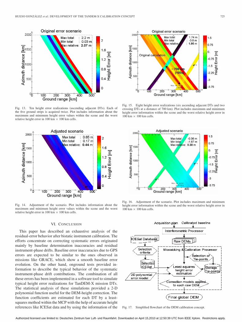
The following simulation has the goal to test the performanceof the adjustment with few high-quality GCPs. In this case,crossing orbits should be acquired at a certain distance fromeach other, crossing the maximum number of parallel DTspossible. Although the acquisition of crossing orbits is notforeseen in the acquisition plan (Section II-B), it could beapplied as a back-up solution in the case of lack of heightreferences in a certain region.
In this simulation, two GCPs are used in the crossing orbits,located at around 100 km from the group of adjacent DTs,as shown in Fig. 15. This compensates the along-track driftof the crossing orbit, which is the reference for the others.Another important conclusion of this simulation is the requireddistance between the crossing orbits in order to get a good errorcorrection.
The calculated error realization and the results of its adjust-ment are shown in Figs. 13 and 14. One GCP is used for theadjustment of this scenario; however, more would be needed ina real case due to the mentioned random errors. The maximumrelative error (in 100 km × 100 km regions and shown inthe lower part of the figures) has been improved from 2.0 to0.44 m, which keeps the height error within the requirements.
C. Consequences for the DEM Calibration Concept
The simulation results point out the need for applying aDEM calibration to the raw DEMs in order to achieve themission accuracy requirements. Simulations were performedfor different Earth regions and DT configurations, and showuseful conclusions.
1) The final relative height accuracy is compliant with thedefined DEM specification, assuming that the phase noisecontributions do not exceed the specified limits, and thesuggested accurate height references are available.
2) The final absolute height accuracy improves the 10-mrequirement of Table I and is on the order of the relativeheight accuracy.
3) In regions close to the equator or with dense vegetation,the GCP density strongly decreases compared with therest of the landmass. In these cases, two long crossingorbits can help to obtain a stable adjustment net and asufficient accuracy.
4) The parallel scenario has two major advantages.a) The same strips are mapped in consecutive years
during the same season. Hence, vegetation, tree cover,or ice cover are monitored in a similar state.
b) It simplifies the processing: the strips are acquiredfrom the same orbit position.
The DEM calibration performance and the final DEM qualitystrongly depend on the precision of the applied height refer-ences. The simulations prove that relatively few highly accurateGCPs (0.5 m-1σ) are needed to achieve the desired heightrequirements. The TanDEM-X DEM calibration plan relies onheight references provided by the Ice, Cloud, and land ElevationSatellite (ICESat) [17] and on the information provided byoverlapping DTs.
Concerning ICESat altimetry data, selection criteria havebeen developed in order to filter the samples and keep theones with best quality [17]. These are usually narrow altimeterpulse returns reflected in flat areas, and their assessed accuracyreaches ∼0.4 m (1σ). The global coverage of the selectedICESat points has been also calculated, showing a sufficientdensity. Almost all the planned DT acquisitions are coveredby several high-quality ICESat data, even in critical regionslike rainforests and equatorial zones. This allows averagingseveral ICESat references. Additionally, as the posting of theTanDEM-X DEM is much finer than the ICESat-laser footprint,the heights have to be averaged with the appropriate weightingfunction before comparison. As most of the selected ICESatpoints lie on flat terrain, no accuracy loss is expected from theaveraging process. The averaging helps to statistically reducepart of the random height error described in Section III-B.
Instead of using the whole overlapping regions for the ad-justment, selected TanDEM-X DEM patches called tie pointsare used. They are strategically located along the plannedoverlapping regions and are regularly stored during the mission.
As already mentioned in Section II-C, the MCP is the oper-ational tool for the TanDEM-X DEM calibration and mosaick-ing. The tool is run once the complete stack of raw DEMs ofa certain region is available. As synthesized in the flowchartof Fig. 17, the algorithm derives, for each DT, the coefficientsof the 2-D height correction function (8) by means of a least-squares method with constraints, aided by the stored heightreferences and tie points located within the interest region.
Fig. 16 shows the simulation results. The maximum relativeerror has improved from 2 to 0.38 m, which meets the heightrequirement of 0.53 m.
The derived height correction functions are applied to thecorresponding DTs, thus obtaining calibrated and mosaickedDEMs. As the SAR images have been previously georeferenced(cf. Section II-C), and no considerable horizontal displacementsof the DEMs are foreseen (as concluded in Section IV-D), justa height adjustment is needed to achieve the desired accuracy.
Authorized licensed use limited to: Deutsches Zentrum fuer Luft- und Raumfahrt. Downloaded on April 15,2010 at 12:50:39 UTC from IEEE Xplore. Restrictions apply.
HUESO GONZÁLEZ et al.: DEVELOPMENT OF THE TANDEM-X CALIBRATION CONCEPT 725
Fig. 13. Ten height error realizations (ascending adjacent DTs). Each ofthe five ground strips is acquired twice. Plot includes information about themaximum and minimum height error values within the scene and the worstrelative height error in 100 km × 100 km cells.
Fig. 14. Adjustment of the scenario. Plot includes information about themaximum and minimum height error values within the scene and the worstrelative height error in 100 km × 100 km cells.
VI. CONCLUSION
This paper has described an exhaustive analysis of theresidual-error behavior after bistatic instrument calibration. Theefforts concentrate on correcting systematic errors originatedmainly by baseline determination inaccuracies and residualinstrument-phase drifts. Baseline error inaccuracies due to GPSerrors are expected to be similar to the ones observed inmissions like GRACE, which show a smooth baseline errorevolution. On the other hand, onground tests provided in-formation to describe the typical behavior of the systematicinstrument-phase drift contributions. The combination of allthese errors has been implemented in a software tool to simulatetypical height error realizations for TanDEM-X mission DTs.The statistical analysis of these simulations provided a 2-Dpolynomial function useful for the DEM-height correction. Thefunction coefficients are estimated for each DT by a least-squares method within the MCP with the help of accurate heightreferences like ICESat data and by using the information of the
Fig. 15. Eight height error realizations (six ascending adjacent DTs and twocrossing DTs at a distance of 700 km). Plot includes maximum and minimumheight error information within the scene and the worst relative height error in100 km × 100 km cells.
Fig. 16. Adjustment of the scenario. Plot includes maximum and minimumheight error information within the scene and the worst relative height error in100 km × 100 km cells.
Fig. 17. Simplified flowchart of the DEM calibration concept.
Authorized licensed use limited to: Deutsches Zentrum fuer Luft- und Raumfahrt. Downloaded on April 15,2010 at 12:50:39 UTC from IEEE Xplore. Restrictions apply.

726 IEEE TRANSACTIONS ON GEOSCIENCE AND REMOTE SENSING, VOL. 48, NO. 2, FEBRUARY 2010
overlapping regions of adjacent DTs. The corresponding heightcorrection 2-D functions need to be finally applied to obtain acalibrated global DEM that fulfils the demanding TanDEM-XDEM relative height requirements. The simulations show thatthe demanding relative height accuracy can be achieved throughthe DEM calibration process. At the same time, the simulationspredict absolute height accuracies far better than the required10 m, assuming the expected availability and quality of heightreferences.
ACKNOWLEDGMENT
The authors would like to thank the anonymous reviewersfor their valuable comments and suggestions to improve thispaper.
REFERENCES
[1] G. Krieger, A. Moreira, H. Fiedler, I. Hajnsek, M. Werner,M. Younis, and M. Zink, “TanDEM-X: A satellite formation forhigh-resolution SAR interferometry,” IEEE Trans. Geosci. Remote Sens.,vol. 45, no. 11, pp. 3317–3341, Nov. 2007.
[2] P. Rosen, S. Hensley, I. Joughin, F. Li, S. Madsen, E. Rodriguez, andR. Goldstein, “Synthetic aperture radar interferometry,” Proc. IEEE,vol. 88, no. 3, pp. 333–382, Mar. 2000.
[3] NGA, MIL PRF 89048 HRTI-3-DEM Draft Document.[4] B. Rabus, M. Eineder, A. Roth, and R. Bamler, “The Shuttle Radar Topog-
raphy Mission (SRTM)—A new class of digital elevation models acquiredby spaceborne radar,” ISPRS J. Photogramm. Remote Sens., vol. 57, no. 4,pp. 241–262, Feb. 2003.
[5] D. Geudtner and M. Zink, “Interferometric calibration of the X-SARsystem on the Shuttle Radar Topography Mission (SRTM/X-SAR),” inProc. 21st Can. Remote Sens. Symp., Ottawa, ON, Canada, Jun. 1999,pp. 558–565.
[6] E. Rodriguez and J. M. Martin, “Theory and design of interferometric syn-thetic aperture radars,” Proc. Inst. Elect. Eng. F—Radar Signal Process.,vol. 139, no. 2, pp. 147–159, Apr. 1992.
[7] M. Lachaise, T. Fritz, and M. Eineder, “A new dual baseline phaseunwrapping algorithm for the TanDEM-X mission,” in Proc. EUSAR,Friedrichshafen, Germany, Jun. 2008.
[8] R. Bamler and M. Eineder, “Accuracy of differential shift estimation bycorrelation and split-bandwidth interferometry for wideband and delta-kSAR systems,” IEEE Geosci. Remote Sens. Lett., vol. 2, no. 2, pp. 152–155, Apr. 2005.
[9] B. Wessel, A. Gruber, J. Hueso Gonzalez, M. Bachmann, andA. Wendleder, “TanDEM-X: DEM calibration concept,” in Proc. IEEEIGARSS, Boston, MA, Jul. 2008, pp. III-111–III-114.
[10] J. Hueso González, M. Bachmann, H. Fiedler, S. Huber, G. Krieger,M. Zink, and B. Wessel, “Development of TanDEM-X DEM calibrationconcept,” in Proc. EURad, Munich, Germany, Oct. 2007, pp. 1743–1746.
[11] G. Krieger and M. Younis, “Impact of oscillator noise in bistatic andmultistatic SAR,” IEEE Geosci. Remote Sens. Lett., vol. 3, no. 3, pp. 424–428, Jul. 2006.
[12] M. Younis, R. Metzig, G. Krieger, and R. Klein, “Performance predictionand verification for bistatic SAR synchronization link,” in Proc. EUSAR,Dresden, Germany, May 2006.
[13] S. Huber, M. Younis, and G. Krieger, “TanDEM-X performance analysis,”in Proc. EUSAR, Friedrichshafen, Germany, Jun. 2008.
[14] O. Montenbruck, L. v. Barneveld, Y. Yoon, and P. Visser, “GPS-based precision baseline reconstruction for the TanDEM-X SAR-formation,” in Proc. 20th Int. Symp. Space Flight Dyn., Annapolis, MD,Sep. 2007.
[15] R. Kroes, O. Montenbruck, W. Bertiger, and P. Visser, “Precise GRACEbaseline determination using GPS,” GPS Solut., vol. 9, no. 1, pp. 21–31,Apr. 2005.
[16] M. Schwerdt, B. Bräutigam, M. Bachmann, B. Döring, D. Schrank, andJ. Hueso González, “TerraSAR-X calibration results,” in Proc. IEEEIGARSS, Boston, MA, Jul. 2008, pp. II-205–II-208.
[17] J. Hueso González, M. Bachmann, R. Scheiber, and G. Krieger,“TanDEM-X DEM calibration and processing experiments with E-SAR,”in Proc. IEEE IGARSS, Boston, MA, Jul. 2008, pp. III-115–III-118.
Jaime Hueso González received the M.S. degree intelecommunication engineering from the Polytech-nic University of Valencia, Valencia, Spain, in 2003.
From 2004 to 2005, he was a Microwave Engineerwith the European Space Agency, Noordwijk, TheNetherlands, where he researched on microwave-filter design, high-power testing, and multipactoreffects on spaceborne microwave waveguides. Since2006, he has been with the German Aerospace Cen-ter (DLR), Wessling, Germany, where he specializeson satellite SAR technology. He has been working as
a Calibration Engineer for projects like TerraSAR-X, TanDEM-X, and GMESSentinel-1. His major research interests include the development of innov-ative calibration concepts for digital elevation models and satellite baselinedetermination.
Markus Bachmann received the Dipl.-Ing. degreein electrical engineering from the Technical Univer-sity of Karlsruhe, Karlsruhe, Germany, in 2005.
Since 2005, he has been with the Microwaves andRadar Institute, German Aerospace Center (DLR),Wessling, Germany, where he is currently a Calibra-tion Engineer in SAR calibration. In the TerraSAR-Xproject, he is responsible for the Antenna Modelcalibration; in TanDEM-X, for the DEM calibrationconcept.
Gerhard Krieger (A’04–M’04) received the Dipl.-Ing. (M.S.) and Dr.-Ing. (Ph.D.) degrees (with hon-ors) in electrical and communication engineeringfrom the Technical University of Munich, Munich,Germany, in 1992 and 1999, respectively.
From 1992 to 1999, he was with the Ludwig-Maximilians University, Munich, where heconducted multidisciplinary research on neuronalmodeling and nonlinear information processingin biological and technical vision systems. Since1999, he has been with the Microwaves and Radar
Institute, German Aerospace Center (DLR), Wessling, Germany, where hedeveloped signal and image processing algorithms for a novel forward lookingradar system employing the principle of digital beamforming on receive. From2001 to 2007, he led the New SAR Missions Group which pioneered thedevelopment of advanced bistatic and multistatic radar systems as exemplifiedby the forthcoming TanDEM-X mission as well as innovative multichannelSAR techniques and algorithms for high-resolution wide-swath SAR imaging.Since 2008, he has been Head of the new Radar Concepts Department.His current research interests focus on the development of multichannelradar techniques and algorithms for innovative MIMO SAR systems, thedemonstration of novel interferometric and tomographic Earth-observationapplications, and the conceptual design of advanced bi- and multistatic radarmissions.
Dr. Krieger is the recipient of several national and international awards,including the IEEE Transactions Prize Paper Award of the Geoscience andRemote Sensing Society and the Otto Lilienthal Sabbatical of the GermanAerospace Center, DLR.
Hauke Fiedler received the Diploma degree inphysics and the Dr. degree in astronomy fromthe Ludwig-Maximilians-Universität of Munich,Munich, Germany, in 1994 and 2000, respectively,and the master degree of Space Systems Engineeringof the Delft University of Technology (TU Delft),Delft, The Netherlands, in 2009.
From 1994, he was in the cataclysmic binarygroup with the Institute of Astronomy and Astro-physics with his work focused on Hard and SoftX-ray Interacting Binaries, Echo-Tomography, ac-
cretion disks and related subjects. Since 2001, he has been with the Microwavesand Radar Institute, German Aerospace Center (DLR), Wessling, Germany,where he is working on future satellite missions for remote sensing withsynthetic aperture radar for the Earth and the Moon, particularly on formationand configuration concepts, bi- and multistatic SAR performance analyses, andsatellite mechanics. He is involved in the TerraSAR-X project and particularlyin the TanDEM-X project.
Authorized licensed use limited to: Deutsches Zentrum fuer Luft- und Raumfahrt. Downloaded on April 15,2010 at 12:50:39 UTC from IEEE Xplore. Restrictions apply.