development of the orion crew-service module umbilical
TRANSCRIPT
DEVELOPMENT OF THE ORION CREW-SERVICE MODULE UMBILICAL
RETENTION AND RELEASE MECHANISM
Damon Delap (1)
, Joel Glidden (2)
, Christopher Lamoreaux (2)
(1) NASA Glenn Research Center, 21000 Brookpark Rd, M/S 86-12, Cleveland, OH 44135 USA, Email: [email protected] (2) Lockheed Martin Space Systems Company, 12257 S Wadsworth Blvd, Littleton, CO 80127 USA, Email:
[email protected], [email protected]
ABSTRACT
The Orion Crew-Service Module umbilical retention and release mechanism supports, protects and disconnects all of the cross-module commodities between the spacecraft’s crew and service modules. These commodities include explosive transfer lines, wiring for power and data, and flexible hoses for ground purge and life support systems. Initial development testing of the mechanism’s separation interface resulted in binding failures due to connector misalignments. The separation interface was redesigned with a robust linear guide system, and the connector separation and boom deployment were separated into two discretely sequenced events. Subsequent analysis and testing verified that the design changes corrected the binding. This umbilical separation design will be used on Exploration Flight Test 1 (EFT-1) as well as all future Orion flights. The design is highly modular and can easily be adapted to other vehicles/modules and alternate commodity sets. 1. INTRODUCTION
Fig. 1 shows the three main modules of the Orion Multi-Purpose Crew Vehicle (MPCV). The subject of this paper is the umbilical connection between the Crew Module (CM) and the Service Module (SM).
The Crew-Service Module (CM/SM) umbilical retention and release mechanism supports and protects all of the cross module commodities between the spacecraft’s crew and service modules. These commodities include explosive transfer lines (ETL), wiring for power and data, and flexible hoses for ground purge and life support systems. Its main functional duty is to safely disconnect the commodity lines and move the hardware out of the way as the CM departs. Some of the main driving requirements of the umbilical separation mechanism are: Separate the commodity connections within a
defined amount of time to ensure compliance with abort and nominal vehicle separation timelines.
Fully separate the SM side of the umbilical within a defined amount of time under nominal conditions.
Initiate the separation only upon receipt of the separation command from the CM.
Prevent recontact of the SM umbilical hardware and the CM for all separation scenarios.
Meet functional and performance requirements after being exposed to acceptance and qualification testing environments.
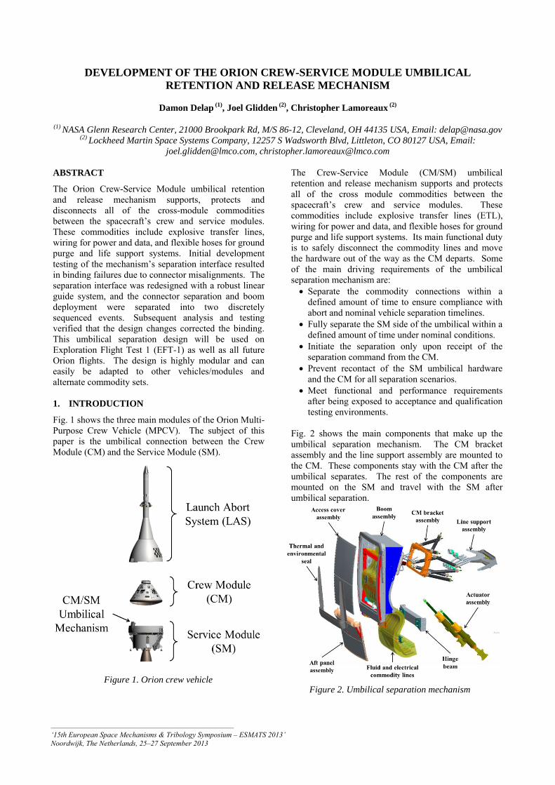
Fig. 2 shows the main components that make up the umbilical separation mechanism. The CM bracket assembly and the line support assembly are mounted to the CM. These components stay with the CM after the umbilical separates. The rest of the components are mounted on the SM and travel with the SM after umbilical separation.
Figure 2. Umbilical separation mechanism Figure 1. Orion crew vehicle
_________________________________________________ ‘15th European Space Mechanisms & Tribology Symposium – ESMATS 2013’ Noordwijk, The Netherlands, 25–27 September 2013

Fig. 3 shows the parts of the two stage plate separation scheme of the umbilical mechanism. The SM plate is shown partially tranparent in order to see the details of the parts within it.
1.1. Two stage umbilical concept of operations
When the CM/SM separation command is received, the center separation bolt fires and releases the first stage of separation (Stage 1). This allows the separation springs in the corners of the SM plate to push the plates apart, which separates all of the connections that go across the interface. The SM plate assembly rides on the guide pin/linear bearing setup and is stopped by a hard stop located on top of the guide pins. A short time after the center bolt fires, the two outside bolts are fired (Stage 2). This releases the umbilical boom assembly and terminates the structural connection of the umbilical to the CM. The boom is then pushed away by the actuator assemblies and locked out in a position that will not interfere with the departing CM (Fig. 4).
2. APOLLO UMBILICAL
The Apollo umbilical (Fig. 5) separation was performed by a pyrotechnically-activated guillotine that had three pyrotechnic charges and four cutting blades (Fig. 6).
All the commodities were packaged into two rectangular blocks that were cut by the redundant blades. These blocks consisted of wires, tubes and four thin metal straps potted in epoxy. Fig. 7 shows the severed commodity blocks on the Command/Service Module (CSM) 117 capsule that was used on the Skylab 3 mission.
The wires, tubes, metal straps and epoxy were the only structural attachment to the CM. Once they were cut, the umbilical arm was free to swing away.
Figure 3. Two stage plate separation components
Figure 4. Stage 2 deployment
Figure 6. Apollo umbilical guillotine cross section
Figure 7. Severed commodity bundles (CSM 117)
Figure 5. Apollo umbilical

3. GUILLOTINE/CONNECTOR TRADE STUDY
Very early on in the design of the umbilical mechanism, a trade study was completed between the guillotine method used by Apollo and the concept of using separation connectors. Lockheed Martin (LM) chose the concept utilizing separation connectors for the following main reasons:
1. It increased the flexibility and decreased the cost at the component level. The guillotine is a one use item and different tubing for each test run would be needed. The connectors would allow the mechanism to be refurbished/reset more quickly and cheaply. The connectors could also be designed for several separations.
2. It was estimated to have less mass by about 40%- 50%.
3. The connectors were considered to have a higher technology readiness level (TRL) and need less development. A guillotine system to cut multiple fluid and electrical lines would be a custom design that would need a large development program.
4. Connectors simplified the assembly and integration process. They are safer to handle and easier to install.
4. BASELINE PLATE SEPARATION DESIGN
Development testing of LM’s baseline plate separation design resulted in binding due to connector misalignments. As a result, the plate separation was redesigned into the two stage scheme described in the Introduction. This section outlines the details of the baseline design and describes its key features. The function of the baseline plate separation scheme was to provide a guided linear separation of the fluid and electrical connectors during the first moments of the umbilical separation in order to inhibit connector binding. The basic assumption for preventing binding was that the connector plates and linear guide components needed to provide angular and lateral control of the connector separation within the advertised misalignment capabilities of the fluid and electrical connectors. Fig. 8 and Fig. 9 show the baseline plate separation design and identify the key components.
Figure 8. Baseline design exploded view
Figure 9. Baseline design cross section
The connector halves were mounted to the CM and SM plates. The motion of these plates disconnected the commodity connections. The spring pack in the middle of the connector plates provided the force to separate the plates and overcome any hindering forces that may be a result of binding, misalignment or damage in the linear guide system or connectors. The springs were packaged this way to reduce mass and make the overall plate design more compact. The guide pins (x2) on SM plate and bushings (x2) on CM plate provided the guidance for the linear separation within the stated misalignment limits of the fluid and electrical connectors. The separation bolts (x2) were designed to fire simultaneously. This single event released the plates as well as the umbilical’s structural connection to the CM. 4.1. Fluid and electrical connectors
The fluid connectors in the umbilical mechanism are a proprietary LM design. They utilize a dual o-ring seal with tight tolerances in order to meet stringent leakage requirements. In the baseline design, the mounting allowed the fluid connectors to float laterally and angularly to accommodate misalignments. The electrical connectors are a zero separation force (ZSF) design similar to the one shown in Fig. 10.
Figure 10. Zero separation force (ZSF) connector
These connectors provide a “zero force separation” by using the wave springs on the plug side to disengage the pins from the sockets. Ideally, an external force is not needed for the connector to separate. 5. BASELINE PLATE SEPARATION
DEVELOPMENT TESTING
During development testing, the plates were fully populated with the fluid and electrical connectors and slowly separated using a tensile testing frame. The test frame measured the force needed to separate the plates. The displacement of each corner of the SM plate was also measured so that the relative plate angle could be calculated. The first instance of binding occurred with the plates at less than one degree relative angle. The plates had separated enough to expose the o-rings from the fluid connectors, indicating that they were not the source of the binding. The plates were decoupled from the test fixture, but the electrical connectors remained mated. A gentle force was applied to the low edge of the SM plate, which caused the connectors to self-separate. Once the connectors were dis-assembled from the plates, it was found that the connectors would not self-separate with their own weight and a slight moment (produced by the wire bundle hanging off to the side). LM tested a second configuration in which the plates were populated with only the fluid connectors. In this configuration, the plates bound up at about two degrees relative angle. Loosening the bolts on one of the fluid connectors relieved the binding. A third configuration was tested which was the same as the second one, but with one modification: the fluid connectors were given freedom to float. The design of the fluid connectors had features that allowed them to float laterally and angularly after being mounted. However, in hindsight LM realized that the mounting scheme of the test setup had counteracted these features and the connectors were not allowed to float as intended during testing of the second configuration. With this change, the plates separated successfully and consistently four times. After review of the data and results, LM determined that the root causes of the baseline design failure were:
1. The electrical and fluid connectors did not have the misalignment capabilities that were expected.
2. The mechanism displayed an instability, or tendency to misalign, which was not anticipated.
LM concluded that the basic premise of the separation method had to change and the team decided to pursue
alternate solutions. 6. TWO STAGE SEPARATION DESIGN AND
ANALYSIS
6.1. Design description
After evaluating many potential solutions, LM selected the two stage separation design described in the Introduction (see Fig. 3). Stage 1 is the closely constrained linear separation of the plates and connectors. Stage 2 is the release of the structural connection to the CM and the rotational motion of the entire umbilical arm. Splitting the umbilical release into two stages allows much more control over the separation event and reduces the binding potential of the mechanism. One of the biggest advantages of this solution is that it preserved the majority of the baseline parts. Most of them, because of schedule constraints, had already been released and were in fabrication at the time of the development testing. The key design features/changes are described in the following subsections. 6.1.1. Separation springs moved to corners
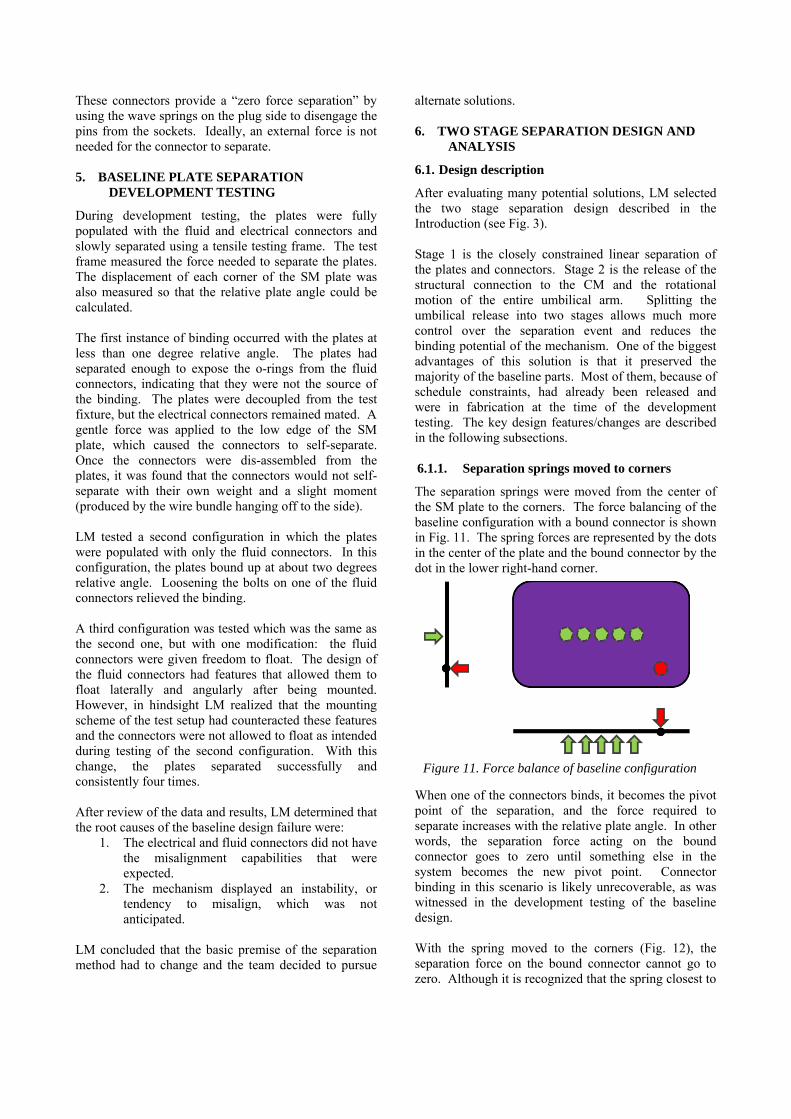
The separation springs were moved from the center of the SM plate to the corners. The force balancing of the baseline configuration with a bound connector is shown in Fig. 11. The spring forces are represented by the dots in the center of the plate and the bound connector by the dot in the lower right-hand corner.
When one of the connectors binds, it becomes the pivot point of the separation, and the force required to separate increases with the relative plate angle. In other words, the separation force acting on the bound connector goes to zero until something else in the system becomes the new pivot point. Connector binding in this scenario is likely unrecoverable, as was witnessed in the development testing of the baseline design. With the spring moved to the corners (Fig. 12), the separation force on the bound connector cannot go to zero. Although it is recognized that the spring closest to
Figure 11. Force balance of baseline configuration

the bound connector has a moment disadvantage relative to the other three springs, the closest spring to it will apply and increasing separation force as the plate angle increases.
6.1.2. Additional separation bolt
In order to perform two discrete separation stages, one more separation bolt was added to the design. Fig. 13 shows the mechanism prior to Stage 1 initiation.
The first stage is released by firing the center bolt. This severs the connection holding the two plates together and allows the SM plate to slide along the guide pins. Fig. 14 shows the position of the plates at the end of Stage 1, just prior to Stage 2 initiation.
The second stage is started by firing the two outside bolts after the linear motion is completed. This releases the structural connection between the umbilical boom and the CM and the umbilical arm is free to rotate away.
6.1.3. Larger guide pins and linear bearings
The diameter and length of the guide pins and linear bearings were increased. They are also more closely toleranced, resulting in a tighter control of plate orientation and more precise plate and connector location. The guide rods do not cross the separation plane as they did in the baseline design and the SM plate rides along the guide rods for the entire Stage 1 stroke. 6.1.4. Redesigned electrical connectors
Due to the tendency of the original off-the-shelf electrical connectors to easily bind up, it was apparent that modifications to the design were necessary. LM worked with the vendor to identify changes that would decrease the tendency for the connectors to bind up. The vendor made some preliminary modifications to the baseline connectors and performed tests to verify that the performance of the connectors improved. LM then developed a specification that they used to procure the flight connectors. 6.1.5. Redesigned fluid connector mounting
Binding occurred in the fluid connectors at much less of angle than anticipated. However, the new plate separation scheme with a tighter control on plate position and relative angularity minimized the needed changes to these connectors. The connectors were changed to a flange mounted scheme that eliminated the angular float and reduced the lateral float. A small amount of lateral float was preserved to help the connector halves self-align while mating. 6.2. Analysis description
An analysis was performed to explore the susceptibility of the two stage linear guide system to binding. This analysis evaluated the geometry of the linear guide system relative to the assisting and hindering forces of the springs and connectors. Specifically, Eq. 1 and Eq. 2 [1] were used to assess the binding condition:
21
s
L (binding condition) (1)
21
s
L (no binding condition) (2)
where L is the driving moment arm of the load, s is the vertical spacing between the two bushings within the
Figure 12. Force balance with springs in corners
Figure 13. Connector plates before Stage 1 initiation
Figure 14. Connector plates at the end of Stage 1

linear bearing and µ is the coefficient of friction between the bearings and the guide pin (see Fig. 15).
The value of s was determined by the geometry of the design, the value of µ was assumed based on materials and expected surface finishes and a critical L (Lcrit) was computed. For the purposes of evaluating this design, Lcrit corresponded to maximum equivalent moment arm of the combined assisting and hindering forces which would result in a no-binding condition. Once Lcrit was calculated, it was compared to the equivalent moment arm calculated by summing all the forces and moments in the umbilical plate separation (Fig. 16) to determine if binding is expected to occur.
LM used the binding analysis as the basis for a Monte Carlo simulation to analytically tune the design and assess its susceptibility to binding under varying conditions and assumptions. The simulation allowed for rapid assessment of numerous trades and contingency scenarios. The variables included spring out scenarios as well as variations in spring force, electrical connector self-separating force, hindering force from the fluid
connectors and the forces expected from bending the fluid lines and electrical harnesses. The four separation springs and the electrical connector springs were simulated individually. A +/- 10% spring force tolerance was used. Each seal port was also simulated individually, but because of more uncertainty in the hindering forces, a +/- 84% tolerance was used on the force. The variance in the forces required to bend the fluid lines and electrical harnesses were reflected in the analysis as a change in the center of gravity (CG) of the SM plate assembly. Four different configurations were simulated:
1. Four in-tolerance separation springs. 2. Three in-tolerance separation springs and one
with one coil out. 3. Zero electrical connector forces. 4. Double electrical connector forces.
10,000 iterations per configuration were run for assessing binding. Because binding and spring strength affect the mechanism’s ability to separate within its prescribed time limit, LM also ran 255 iterations per configuration to evaluate the plate separation time duration. 6.3. Analysis results
Fig. 17 shows an example of the results that were obtained from the Monte Carlo analysis for binding. This particular plot shows the resultant moment arm location for Configuration 1. The dashed circle represents the region that corresponds to a no-binding condition (i.e. the resultant equivalent moment arm is less than Lcrit). In this configuration, zero binding cases were found. Similar plots were generated for the other configurations and all cases were found to be well within the no-binding region. The data indicates that the design is most sensitive to variances in the CG location.
Figure 15. Binding equation variables
Figure 16. Resulting moment arm of the forces
present during plate separation
Figure 17. Binding analysis results for Configuration 1
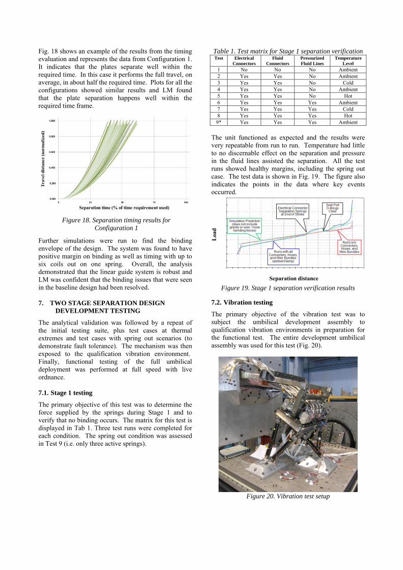
Fig. 18 shows an example of the results from the timing evaluation and represents the data from Configuration 1. It indicates that the plates separate well within the required time. In this case it performs the full travel, on average, in about half the required time. Plots for all the configurations showed similar results and LM found that the plate separation happens well within the required time frame.
Further simulations were run to find the binding envelope of the design. The system was found to have positive margin on binding as well as timing with up to six coils out on one spring. Overall, the analysis demonstrated that the linear guide system is robust and LM was confident that the binding issues that were seen in the baseline design had been resolved. 7. TWO STAGE SEPARATION DESIGN
DEVELOPMENT TESTING
The analytical validation was followed by a repeat of the initial testing suite, plus test cases at thermal extremes and test cases with spring out scenarios (to demonstrate fault tolerance). The mechanism was then exposed to the qualification vibration environment. Finally, functional testing of the full umbilical deployment was performed at full speed with live ordnance. 7.1. Stage 1 testing
The primary objective of this test was to determine the force supplied by the springs during Stage 1 and to verify that no binding occurs. The matrix for this test is displayed in Tab 1. Three test runs were completed for each condition. The spring out condition was assessed in Test 9 (i.e. only three active springs).
Table 1. Test matrix for Stage 1 separation verification Test Electrical
Connectors
Fluid
Connectors
Pressurized
Fluid Lines
Temperature
Level
1 No No No Ambient 2 Yes Yes No Ambient 3 Yes Yes No Cold 4 Yes Yes No Ambient 5 Yes Yes No Hot 6 Yes Yes Yes Ambient 7 Yes Yes Yes Cold 8 Yes Yes Yes Hot 9* Yes Yes Yes Ambient
The unit functioned as expected and the results were very repeatable from run to run. Temperature had little to no discernable effect on the separation and pressure in the fluid lines assisted the separation. All the test runs showed healthy margins, including the spring out case. The test data is shown in Fig. 19. The figure also indicates the points in the data where key events occurred.
7.2. Vibration testing
The primary objective of the vibration test was to subject the umbilical development assembly to qualification vibration environments in preparation for the functional test. The entire development umbilical assembly was used for this test (Fig. 20).
Figure 20. Vibration test setup
Figure 18. Separation timing results for
Configuration 1
Figure 19. Stage 1 separation verification results

Results showed that the desired levels were achieved in all three axes with no significant issues. 7.3. Functional testing
This set of testing had two main objectives: 1. Measure and record the source shock
environment associated with the actuation of the three pyrotechnic separation bolts used in the separation event.
2. Demonstrate that the two stage separation design successfully separated after exposure to qualification vibration levels.
During this test both Stage 1 and Stage 2 were activated. Two test runs were completed, with minor refurbishment required in between the test runs. The results showed that the measured shock from the umbilical separation bolts did not pose a threat to the umbilical hardware and the shock models needed only minor alterations. From a mechanisms standpoint, the two stages separated as expected. Post-test inspections showed no unexpected damage or wear in the condition of the hardware. Based on the results from this test, LM decided to move forward with the two stage design for the flight umbilical mechanism. 8. LESSONS LEARNED
The linear guide system needed to be the dominant element for controlling the plate orientation and connector positioning. Allowing too much play in the guide system and connector mounting (in an attempt to allow the connectors to float to prevent binding) did not work well. Dividing the umbilical separation into two carefully constrained and timed events addressed the root cause of the binding failures by providing better control of the plate orientation. The off-the-shelf electrical connector design did not perform as expected in the umbilical mechanism application. The cost and schedule impacts from writing a specification and purchasing validated connectors could have been partially mitigated by verifying the actual performance of the off-the-shelf connector design. The separation force from the plate springs is more effective when distributed to the corners of the plates. This provided a more stable application of the separation force. Furthermore, it ensured that there would never be zero separation force being applied to a bound connector. The Monte Carlo simulation was very effective in dealing with the number of variables affecting the separation and the uncertainty associated with each one. It allowed for rapid assessment of numerous trades
and contingency scenarios. The envelope of the design was quickly and effectively identified. It gave LM confidence that this separation configuration met force and timing margins. Finally, development testing of the CSM umbilical retention and release mechanism proved to be essential in discovering unknown and unanticipated issues and helped to validate analytical predictions. 9. CONCLUSIONS
The analysis and testing results of the two stage plate separation design indicate that the mechanism will operate well during flight acceptance and qualification testing as well as the EFT-1 mission. The method of separating a cluster of fluid, electrical and pyrotechnic connectors used in the CM/SM umbilical mechanism can be used in many applications. The analysis methods for assessing the binding potential and mechanism timing can be easily changed to accommodate different connector configurations and commodity sets. LM will continue to develop this umbilical connection for Orion missions beyond EFT-1 and hopes to use it in future applications. 10. REFERENCES
1. PBC Linear (2009). PBC Linear Motion Catalog. Online at http://www.pbclinear.com (as of 10 July 2013), p48.