development of the ch-dtl accelerating structure
DESCRIPTION
Development of the CH-DTL accelerating structure. Ulrich Ratzinger Institute for Applied Physics, J.W. Goethe University, Frankfurt. CERN, Geneva Annual Care Meeting, November 23 rd - 25 th , 2005. Proton acceleration up to 100 MeV H-Linac and the CH-DTL: general overview and properties - PowerPoint PPT PresentationTRANSCRIPT
Development of the CH-DTL accelerating structure
Ulrich Ratzinger
Institute for Applied Physics, J.W. Goethe University, Frankfurt
CERN, Geneva
Annual Care Meeting, November 23rd - 25th, 2005

Overview
Proton acceleration up to 100 MeV H-Linac and the CH-DTL: general overview and properties Konus Beam Dynamics The 70 MeV, 70 mA Proton Injector at GSI-FAIR The Superconducting CH – development Summary Team members
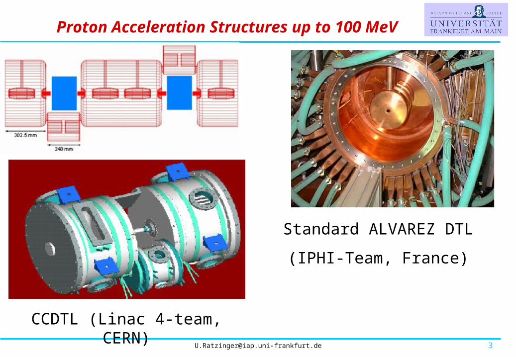
Proton Acceleration Structures up to 100 MeV
CCDTL (Linac 4-team, CERN)
Standard ALVAREZ DTL
(IPHI-Team, France)

The IH Linac [3]
View of the 0.4 -7 A MeV C4+ IH Injector for HICAT-Heidelberg
IAP-Frankfurt University
GSI, Darmstadt

The CH-DTL
The CH-DTL operates in the H21(0) Mode and, at beam energies between 5 and 150 AMeV, it shows a large potential[3] as well for room temperature as for superconducting designs. At the moment besides IAP, ANL and FNAL[4] are considering CH-Cavities for proton acceleration.

KONUS Beam Dynamics [3]
The Shunt Impedance of the H-type linacs can be quite high:
Main Characteristics:
slim drift tubes, effective field grad. up to 7 MV/m, KONUS Beam Dynamics:

KONUS Beam Dynamics
The KONUS has been successfully applied in many projects as the Pb Injector at CERN, the HSI and HLI at GSI and the TRIUMF ISAC Facility, and it is implemented in several actual projects.
Konus principle108 MHz GSI Cavity

Layout of the GSI-FAIR Project [1]
For the p-bar project at the High Energy Storage Ring (HESR) a particle number in the SIS18 of ~ 6 x10¹² p/cycle is requested. This will be provided by a 10 turn injection of a 70 MeV, 70 mA beam from the new proton injector linac.
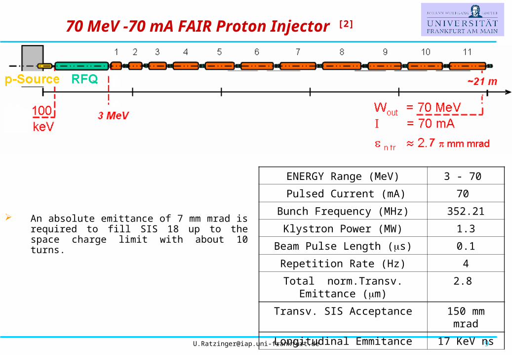
ENERGY Range (MeV) 3 - 70
Pulsed Current (mA) 70
Bunch Frequency (MHz) 352.21
Klystron Power (MW) 1.3
Beam Pulse Length (s) 0.1
Repetition Rate (Hz) 4
Total norm.Transv. Emittance (m) 2.8
Transv. SIS Acceptance 150 mm mrad
Longitudinal Emmitance 17 KeV ns
An absolute emittance of 7 mm mrad is required to fill SIS 18 up to the space charge limit with about 10 turns.
70 MeV -70 mA FAIR Proton Injector [2]
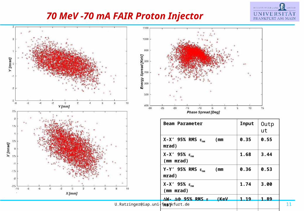
Beam Parameter Input Output
X-X’ 95% RMS nm (mm mrad) 0.35 0.55
X-X’ 95% nm (mm mrad) 1.68 3.44
Y-Y’ 95% RMS nm (mm mrad) 0.36 0.53
X-X’ 95% nm (mm mrad) 1.74 3.00
W- 95% RMS (KeV ns) 1.19 1.89
W- 95% (KeV ns) 9.00 13.62
Transmission Rate 100 %
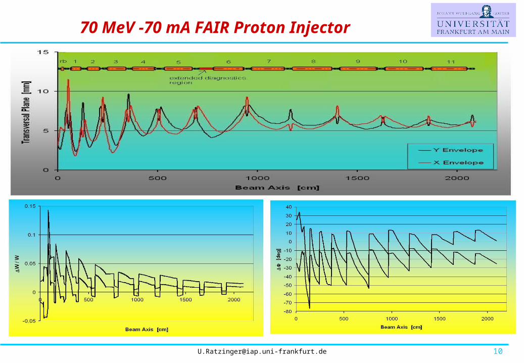
70 MeV -70 mA FAIR Proton Injector

Resonant End Cells [6]
Standard IH design with undercuts
(realisation of the “0” Mode)
CH design: end half drift tubes with enlarged diameter result in resonant end-cells at an optimized length
End half drift tube

Longitudinal Field Distribution
Example of a typical field distribution inside a short tuned CH - cavity.

CH-Linac Array
The result will be a very compact structure with an RF power requirement below 1 MW for each individual cavity. The linac will be mounted on rails and the intertank flanges could be easily opened to perform any kind of maintenance.
Housing of quadruples and of diagnostics

Prototype CH-Cavity Development
Construction of an 8-gap prototype cavity (β/2 =45 mm)
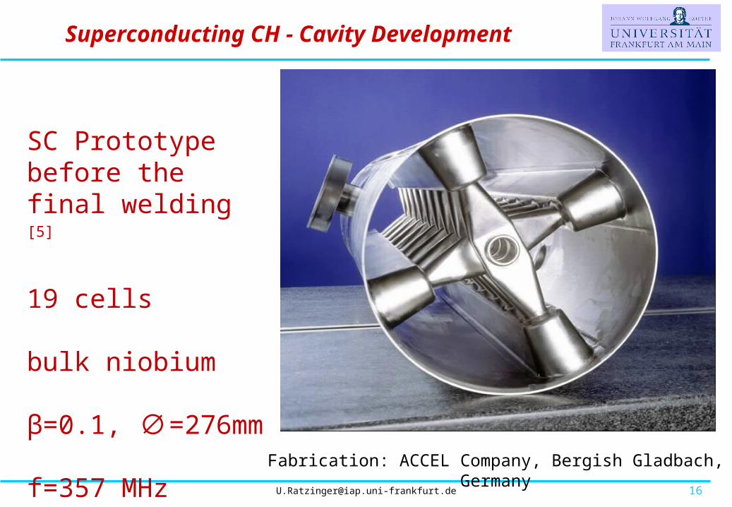
SC Prototype before the final welding [5]
19 cells bulk niobium
β=0.1, ∅=276mm
f=357 MHz
Superconducting CH - Cavity Development
Fabrication: ACCEL Company, Bergish Gladbach, Germany

CH-cavity ready for the test in
Frankfurt
T-sensors
Superconducting CH - Cavity Development
Stabilizing Rings


Q0 versus Gradient/Voltage
L=n/2=9.5Ep = 23.8 MV/m
Bp = 26 mT
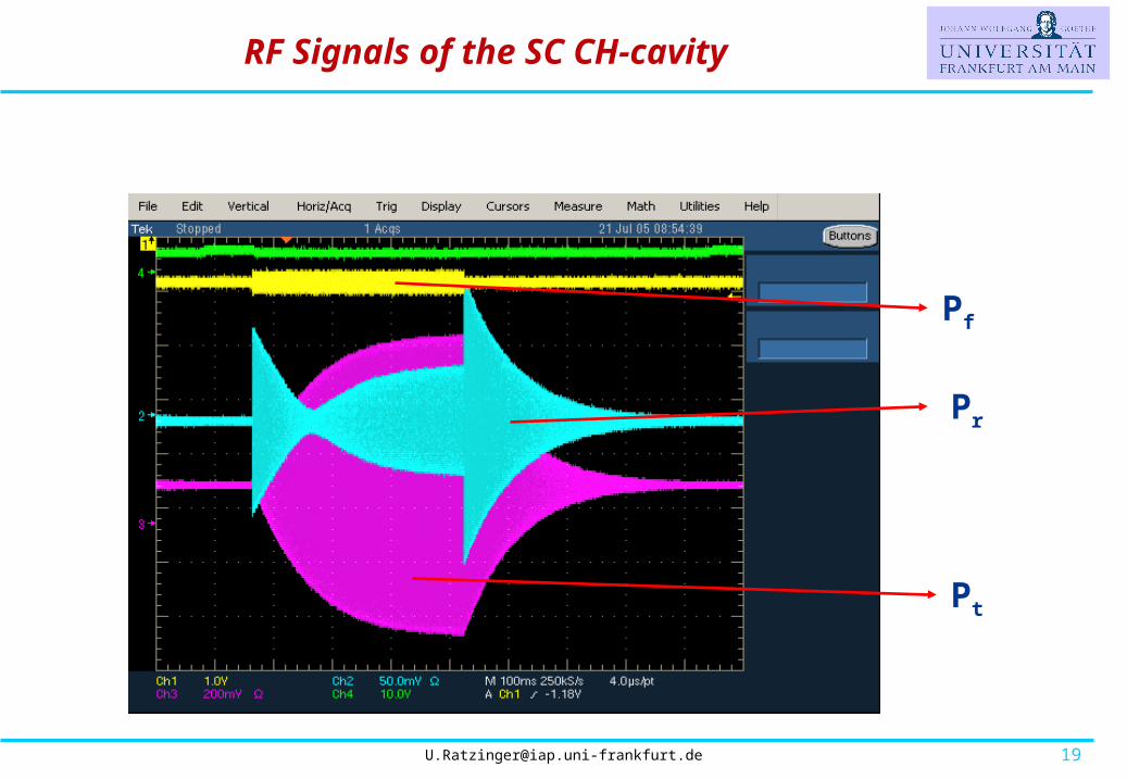
Superconducting CH - Cavity Measurements

Summary and Outlook
The CH-type structure looks promising for beam energies up to
about 100 AMeV. Room temperature as well as superconducting versions are under
development. The stem configuration allows for a very efficient water cooling
of r.t. CH – structures. The KONUS beam dynamics allows to realize simple cavities without
internal focusing lenses. Intertank lenses can be well integrated at a minimum request of extra drift
space. A CH-DTL is developed for high current proton injection into the FAIR
facility at GSI, Darmstadt.

People and Institutes
J.W.Goethe University, Frankfurt am Main- IAP
G.Clemente, H.Liebermann, H.Podlech, U.Ratzinger R.Tiede, A.Sauer
S.Minaev (ITEP, IAP Guest) GSI, Darmstadt- LINAC TEAM W.Barth, L.Groening, K. Dermati.

Bibliography
[1] “The Future GSI Facility: beams of ions and antiprotons”. H. Henning, Proceed. of the PAC ‘03, Portland, Oregon.
[2] “The 70 MeV p-Injector for FAIR”. U.Ratzinger et al, AIP Conference Proceedings, 2005,
Volume 773, pp. 249-253 .
[3] “Habilitationsschrift”. U.Ratzinger, Frankfurt University
[4] “Front End Design of a Multi-GeV H-Minus Linac”. P.N. Ostrumov et al., Proceed. of the PAC ‘05, Knoxville, Tennessee, May 14-23 2005.
[5] “Development of superconducting CH-Structures for low and medium beta beams and the status of the 352 MHz prototype cavity”, H.Podlech et al, AIP Conference Proceedings, 2005, Volume 773, pp. 107-109.
[6] “Development of a normal conducting CH-DTL” G.Clemente et al., Proceed. Of the PAC ‘05 Conference, Knoxville, Tennessee, May 14-23 2005.