development of radiation medicine at dlnp, jinr · development of radiation medicine at dlnp, jinr...
TRANSCRIPT
�¨¸Ó³ ¢ �—�Ÿ. 2011. ’. 8, º4(167). ‘. 635Ä646
”ˆ‡ˆŠ� ˆ ’…•�ˆŠ� “‘Š��ˆ’…‹…‰
DEVELOPMENT OF RADIATION MEDICINEAT DLNP, JINR
E. M. Syresin, A. V. Agapov, N. V. Anˇmov, G. A. Chelkov, V. N. Gaevsky,V. G. Elkin, G. A. Karamysheva, M. Yu. Kazarinov, N. N.Khovansky,
S. A. Kostromin, V. G.Kruchonok, Z. V. Krumshtein, E. I. Luchin, G. V. Mitsyn,A. G. Molokanov, N. A. Morozov, A. G. Olshevsky, V. M. Romanov,
Z. Ya. Sadygov, E. V. Samsonov, A. S. Selyunin, N.G. Shakun, K. N. Shipulin,G.D. Shirkov, S. V. Shvidky, A. S. Zhemchugov
Joint Institute for Nuclear Research, Dubna
V. A. Novikov, O. P. Tolbanov, A. V. TyazhevAcademician V.D. Kouznetsov Siberian Physical and Technical Institute, Tomsk State University,
Tomsk, Russia
Y. JongenIon Beam Application, Louvain-la-Neuve, Belgium
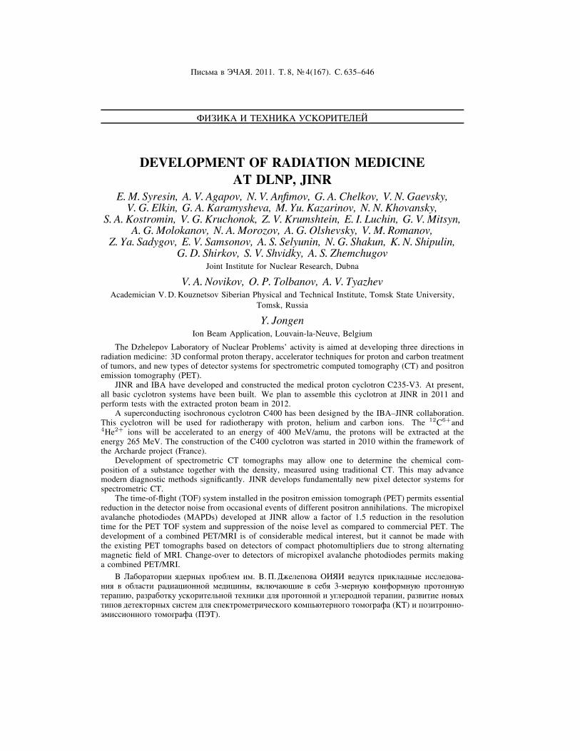
The Dzhelepov Laboratory of Nuclear Problems' activity is aimed at developing three directions inradiation medicine: 3D conformal proton therapy, accelerator techniques for proton and carbon treatmentof tumors, and new types of detector systems for spectrometric computed tomography (CT) and positronemission tomography (PET).
JINR and IBA have developed and constructed the medical proton cyclotron C235-V3. At present,all basic cyclotron systems have been built. We plan to assemble this cyclotron at JINR in 2011 andperform tests with the extracted proton beam in 2012.
A superconducting isochronous cyclotron C400 has been designed by the IBAÄJINR collaboration.This cyclotron will be used for radiotherapy with proton, helium and carbon ions. The 12C6+and4He2+ ions will be accelerated to an energy of 400 MeV/amu, the protons will be extracted at theenergy 265 MeV. The construction of the C400 cyclotron was started in 2010 within the framework ofthe Archarde project (France).
Development of spectrometric CT tomographs may allow one to determine the chemical com-position of a substance together with the density, measured using traditional CT. This may advancemodern diagnostic methods signiˇcantly. JINR develops fundamentally new pixel detector systems forspectrometric CT.
The time-of-ight (TOF) system installed in the positron emission tomograph (PET) permits essentialreduction in the detector noise from occasional events of different positron annihilations. The micropixelavalanche photodiodes (MAPDs) developed at JINR allow a factor of 1.5 reduction in the resolutiontime for the PET TOF system and suppression of the noise level as compared to commercial PET. Thedevelopment of a combined PET/MRI is of considerable medical interest, but it cannot be made withthe existing PET tomographs based on detectors of compact photomultipliers due to strong alternatingmagnetic ˇeld of MRI. Change-over to detectors of micropixel avalanche photodiodes permits makinga combined PET/MRI.
‚ ‹ ¡μ· Éμ·¨¨ Ö¤¥·´ÒÌ ¶·μ¡²¥³ ¨³. ‚. �. „¦¥²¥¶μ¢ �ˆŸˆ ¢¥¤ÊÉ¸Ö ¶·¨±² ¤´Ò¥ ¨¸¸²¥¤μ¢ -´¨Ö ¢ μ¡² ¸É¨ · ¤¨ Í¨μ´´μ° ³¥¤¨Í¨´Ò, ¢±²ÕÎ ÕШ¥ ¢ ¸¥¡Ö 3-³¥·´ÊÕ ±μ´Ëμ·³´ÊÕ ¶·μÉμ´´ÊÕÉ¥· ¶¨Õ, · §· ¡μÉ±Ê Ê¸±μ·¨É¥²Ó´μ° ɥ̴¨±¨ ¤²Ö ¶·μÉμ´´μ° ¨ Ê£²¥·μ¤´μ° É¥· ¶¨¨, · §¢¨É¨¥ ´μ¢ÒÌɨ¶μ¢ ¤¥É¥±Éμ·´ÒÌ ¸¨¸É¥³ ¤²Ö ¸¶¥±É·μ³¥É·¨Î¥¸±μ£μ ±μ³¶ÓÕÉ¥·´μ£μ Éμ³μ£· Ë (Š’) ¨ ¶μ§¨É·μ´´μ-Ô³¨¸¸¨μ´´μ£μ Éμ³μ£· Ë (��’).

636 Syresin E. M. et al.
�ˆŸˆ ¸μ¢³¥¸É´μ ¸ ¡¥²Ó£¨°¸±μ° ˨·³μ° IBA μ¸ÊÐ¥¸É¢¨² · §· ¡μÉ±Ê ¸¶¥Í¨ ²¨§¨·μ¢ ´´μ£μ³¥¤¨Í¨´¸±μ£μ ͨ±²μÉ·μ´ ‘235-V3 ¤²Ö ¶·μÉμ´´μ° É¥· ¶¨¨. ‚ ´ ¸ÉμÖÐ¥¥ ¢·¥³Ö ¨§£μÉμ¢²¥´Ò ¢¸¥μ¸´μ¢´Ò¥ ¸¨¸É¥³Ò ͨ±²μÉ·μ´ . ‚ 2011 £. ¶² ´¨·Ê¥É¸Ö ¶·μ¢¥¸É¨ ¥£μ ¸¡μ·±Ê ¢ �ˆŸˆ, ¢ 2012 £. Å¥£μ ¨¸¶ÒÉ ´¨Ö ¸ ¢Ò¢¥¤¥´´Ò³ ¶·μÉμ´´Ò³ ¶Êαμ³.
‘¢¥·Ì¶·μ¢μ¤ÖШ° ¨§μÌ·μ´´Ò° ͨ±²μÉ·μ´ C400, ¶·¥¤´ §´ Î¥´´Ò° ¤²Ö Ê£²¥·μ¤´μ° É¥· ¶¨¨,· §· ¡μÉ ´ ¸μ¢³¥¸É´μ �ˆŸˆ ¨ IBA. �ÉμÉ Í¨±²μÉ·μ´ ¡Ê¤¥É ¨¸¶μ²Ó§μ¢ ÉÓ¸Ö ¤²Ö · ¤¨μÉ¥· ¶¨¨ ¶·μ-Éμ´ ³¨, ¨μ´ ³¨ £¥²¨Ö ¨ ¨μ´ ³¨ Ê£²¥·μ¤ . ˆμ´Ò Ê£²¥·μ¤ ¨ £¥²¨Ö ¡Ê¤ÊÉ Ê¸±μ·¥´Ò ¤μ Ô´¥·£¨¨400 MÔ‚/´Ê±²μ´, ¶·μÉμ´Ò ¢Ò¢¥¤¥´Ò ¨§ ͨ±²μÉ·μ´ ¶·¨ Ô´¥·£¨¨ 265 MÔ‚. ˆ§£μÉμ¢²¥´¨¥ ͨ±²μ-É·μ´ ‘400 ´ Î Éμ ¢ 2010 £. ¢ · ³± Ì ¶·μ¥±É ®Archarde¯ (”· ´Í¨Ö).
� §· ¡μɱ ¸¶¥±É·μ³¥É·¨Î¥¸±μ£μ Š’ ¶μ§¢μ²¨É μ¶·¥¤¥²ÖÉÓ Ì¨³¨Î¥¸±¨° ¸μ¸É ¢ ¨¸¸²¥¤Ê¥³μ£μ ¢¥-Ð¥¸É¢ ´ ·Ö¤Ê ¸ ¥£μ ¶²μÉ´μ¸ÉÓÕ, ¨§³¥·Ö¥³μ° ¸ ¶μ³μÐÓÕ ¸É ´¤ ·É´ÒÌ Š’. �Éμ ³μ¦¥É μ¡¥¸¶¥Î¨ÉÓ¸ÊÐ¥¸É¢¥´´μ¥ · §¢¨É¨¥ ³¥É줨±¨ ¨ ¢μ§³μ¦´μ¸É¥° ±μ³¶ÓÕÉ¥·´μ° Éμ³μ£· ˨¨. �ˆŸˆ · §· ¡ ÉÒ¢ ¥É¶·¨´Í¨¶¨ ²Ó´μ ´μ¢Ò° ¶μ²Ê¶·μ¢μ¤´¨±μ¢Ò° ¶¨±¸¥²Ó´Ò° ¤¥É¥±Éμ· ´ μ¸´μ¢¥ GaAs(Cr) ¤²Ö ¸¶¥±É·μ-³¥É·¨Î¥¸±μ£μ Š’.
‚·¥³Ö¶·μ²¥É´ Ö ¸¨¸É¥³ ��’ §´ Ψɥ²Ó´μ ¸μ±· Ð ¥É ±μ²¨Î¥¸É¢μ ²μ¦´ÒÌ ¸· ¡ ÉÒ¢ ´¨° ¥£μ¤¥É¥±Éμ·´μ° ¸¨¸É¥³Ò, ¢μ§´¨± ÕÐ¨Ì μÉ · §´ÒÌ ´´¨£¨²ÖÍ¨μ´´ÒÌ ¸μ¡Òɨ°. Œ¨±·μ¶¨±¸¥²Ó´Ò° Ëμ-É줨μ¤, · §· ¡ ÉÒ¢ ¥³Ò° ¢ �ˆŸˆ, ¶μ§¢μ²Ö¥É ¢ 1,5 · § Ê¢¥²¨Î¨ÉÓ ¢·¥³Ö¶·μ²¥É´μ¥ · §·¥Ï¥´¨¥ ¨,¸μμÉ¢¥É¸É¢¥´´μ, §´ Ψɥ²Ó´μ ¸´¨§¨ÉÓ Ê·μ¢¥´Ó ÏÊ³μ¢ ¶μ ¸· ¢´¥´¨Õ ¸ ±μ³³¥·Î¥¸±¨³¨ ��’. � §· -¡μɱ ¸μ¢³¥Ð¥´´μ£μ ��’/Œ�’ Éμ³μ£· Ë ¶·¥¤¸É ¢²Ö¥É §´ Ψɥ²Ó´Ò° ¨´É¥·¥¸ ¤²Ö ¶· ±É¨Î¥¸±μ°³¥¤¨Í¨´Ò. ’ ±μ° Éμ³μ£· Ë ´¥ ³μ¦¥É ¡ÒÉÓ ¨§£μÉμ¢²¥´ ´ μ¸´μ¢¥ ËμÉμʳ´μ¦¨É¥²¥° Å ¸μ¢·¥³¥´-´μ° ¤¥É¥±Éμ·´μ° ¡ §¥ ��’. ˆ¸¶μ²Ó§μ¢ ´¨¥ ³¨±·μ¶¨±¸¥²Ó´ÒÌ ËμÉ줨μ¤μ¢ ¶μ§¢μ²Ö¥É ·¥Ï¨ÉÓ ÔÉʶ·μ¡²¥³Ê ¨ ¸μ§¤ ÉÓ ¸μ¢³¥Ð¥´´Ò° ��’/Œ�’ Éμ³μ£· Ë.
PACS: 87.56.-v; 87.64.-t; 87.80.-y
PROTON THERAPY
Dubna is one of the leading proton therapy research centers in Russia [1]. The JINRMedico-Technical Complex (MTC) consists of seven rooms, where proton, pion and neutronbeams are used [1Ä3]. The research synchrocyclotron with a proton energy of 660 MeV andcurrent of 3 μA has been used for medical applications since 1967. The modern techniqueof 3D conformal proton radiotherapy was ˇrst effectuated in Russia at this center, and now itis effectively used in regular treatment sessions [1Ä3]. The irradiated dose distribution in 3Dconformal proton therapy coincides with the tumor target shape with an accuracy of 1 mm.This required solving the following tasks: formation and monitoring of proton beams withthe required parameters; development of the computer codes and a technique for construction
Fig. 1. Proton therapy in medical cabin 1 of JINR MTC

Development of Radiation Medicine at DLNP, JINR 637
Table 1. Diseases treated at JINR by the proton medical beams in 1999Ä2010
Disease Number of patientsMeningioma 118Chordoma, chordosarkoma 21Glioma 45Acoustic Neurinoma 9Astrocytoma 27Paraganglioma 5Pituitary Adenoma 21AVM 62Brain and other metastase 56Other head and neck tumors 175Melanoma 11Skin diseases 43Carcinoma metastase of the lung 9Breast cancer 46Prostate Adenoma 1Sarcoma 13Others 25Total 687
of individual collimators and boluses; development of a system for immobilization of thepatient and veriˇcation of its position relative to the proton beam. The equipment used for3D conformal therapy in room 1 is presented in Fig. 1. About 100 patients undergo a courseof fractionated treatment here every year. About 700 patients were treated by proton beamsduring the last 10 years (Table 1).
PROTON CYCLOTRON C235-V3
The C235-V3 cyclotron, superior in its parameters to the IBA C235 medical protoncyclotron installed in 10 proton treatment centers of the world, has been designed and manu-factured by the JINRÄIBA collaboration. This cyclotron is an essentially modiˇed version ofIBA C235 cyclotron [4, 5] (Table 2).
One of the goals is to modify the sector spiral angle at R > 80 cm for improving thecyclotron working diagram (Fig. 2) and reducing of coherent beam losses at acceleration. Thecoherent beam displacement z from the median plane is deˇned by the vertical betatron tuneQz: z ∝ Q−2
z . At Qz ≈ 0.2 the coherent beam displacement corresponds to 7 mm and atthe free axial oscillation amplitude of 2Ä3 mm can cause beam losses due to reduction of thesector gap in the C235 cyclotron. An increase of the vertical betatron tune from Qz ≈ 0.2Ä0.25 to Qz ≈ 0.4 in C235-V3 permits the coherent losses at proton acceleration to be reducedby a factor of 3Ä4 (Table 2).
Modiˇcation of the extraction system is another aim of the new C235-V3 cyclotron [4].The main peculiarity of the cyclotron extraction system is a rather small gap (9 mm) betweenthe sectors in this area. The septum surface consists of several parts of circumferences ofdifferent radii. The septum thickness is linearly increased from 0.1 mm at the entrance to3 mm at the exit. The proton extraction losses essentially depend on the septum geometry. In
638 Syresin E. M. et al.
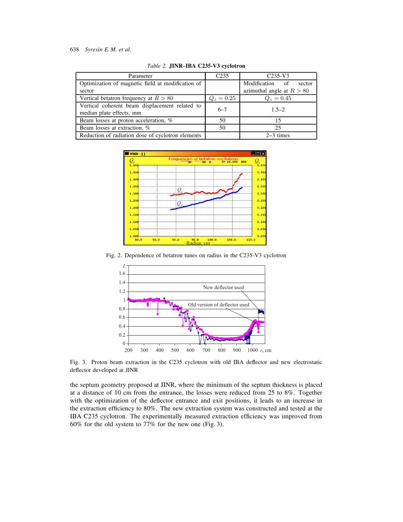
Table 2. JINRÄIBA C235-V3 cyclotron
Parameter C235 C235-V3Optimization of magnetic ˇeld at modiˇcation ofsector
Modiˇcation of sectorazimuthal angle at R > 80
Vertical betatron frequency at R > 80 Qz = 0.25 Qz = 0.45
Vertical coherent beam displacement related tomedian plate effects, mm
6Ä7 1.5Ä2
Beam losses at proton acceleration, % 50 15Beam losses at extraction, % 50 25Reduction of radiation dose of cyclotron elements 2Ä3 times
Fig. 2. Dependence of betatron tunes on radius in the C235-V3 cyclotron
Fig. 3. Proton beam extraction in the C235 cyclotron with old IBA deector and new electrostatic
deector developed at JINR
the septum geometry proposed at JINR, where the minimum of the septum thickness is placedat a distance of 10 cm from the entrance, the losses were reduced from 25 to 8%. Togetherwith the optimization of the deector entrance and exit positions, it leads to an increase inthe extraction efˇciency to 80%. The new extraction system was constructed and tested at theIBA C235 cyclotron. The experimentally measured extraction efˇciency was improved from60% for the old system to 77% for the new one (Fig. 3).

Development of Radiation Medicine at DLNP, JINR 639
Fig. 4. Beam intensity variation at the IBA C235 proton cyclotron
Advantages of the medical proton cyclotron are simplicity, reliability, small size, and, mostimportantly, the ability to modulate rapidly and accurately the proton beam current (Fig. 4).The current modulation of the extracted proton beam at a frequency of up to 1 kHz [5] ismost advantageous with Pencil Beam Scanning and Intensity Modulated Proton Therapy. Theenergy of the extracted beam in the cyclotron is ˇxed. However, the fast proton energyvariation at a rate of 15 MeV/s is easily performed during active cancer treatment by using awedge degrader. This energy variation rate is faster than in the typical synchrotron regime.
SUPECONDUCTING CYCLOTRON C400 APPLIED FOR CARBON THERAPY
Carbon therapy is the most effective method to treat resistant tumors. A compact super-conducting isochronous cyclotron C400 (Fig. 5) was designed by the JINRÄIBA collaboration(Table 3) [5Ä9]. This cyclotron will be used for radiotherapy with protons, helium and carbonions. The 12C6+ and 4He2+ ions will be accelerated to an energy of 400 MeV/amu andH+
2 ions will be accelerated to an energy of 265 MeV/amu, and protons will be extracted bystripping.
Fig. 5. General view of the C400 cyclotron

640 Syresin E. M. et al.
Table 3. Main parameters of the C400 cyclotron
General properties
Accelerated particles H+2 , 4He2+, 6Li3+, 10B5+, 12C6+
Injection energy, keV/Z 25Final energy of:ions 400 MeV/amuprotons 265 MeVExtraction efˇciency, % ∼ 70 ( by deector)Number of turns ∼ 1700
Magnetic systemTotal weight, t 700Outer diameter, m 6.6Height, m 3.4Pole radius, m 1.87Valley depth, cm 60Bending limit K = 1600
Hill ˇeld, T 4.5Valley ˇeld, T 2.45
RF systemRadial dimension, cm 187Vertical dimension, cm 116Frequency, MHz 75Operation 4 harmonicNumber of dees 2Dee voltage, kV:center 80extraction 170
Three external ion sources will be mounted on the switching magnet in the injection linelocated below the cyclotron. The 12C6+ions are produced by a high-performance ECR at aninjection current of 3 μA. The alphas are produced by the other ECR source, while H+
2 areproduced by a multicusp ion source. All species have a Q/M ratio of 1/2.
The dee tips have the vertical aperture 1.2 cm in the ˇrst turn and 2 cm in the second andsubsequent turns. In the ˇrst turn the gaps were delimited with pillars reducing the transittime. The azimuth extension between the middles of the accelerating gaps was chosen to be45◦. The electric ˇeld in the inector was chosen to be 20 kV/cm. Thus, the height (electricradius) of the inector is 2.5 cm. The gap between the electrodes was taken to be 6 mm,and the tilt parameter is k′ = 0.1. The aspect ratio between the width and the spacing of theelectrodes was taken to be 2 to avoid the fringe ˇeld effect.
The 3D TOSCA simulation (Fig. 6) and the design of the C400 magnetic system werebased on the main characteristics of the cyclotron: four-fold symmetry and spiral sectors;deep-valley concept with RF cavities placed in the valleys; elliptical pole gap decreasingfrom 120 mm at the center to 12 mm at the extraction; proton acceleration up to a distanceof 10 mm from the pole edge to facilitate extraction; pole radius 187 cm; hill ˇeld 4.5 T,valley ˇeld 2.45 T; magnetic induction inside yoke less than 2Ä2.2 T; the magnet weight700 tons and the magnet yoke diameter 6.6 m; the main coil current 1.2 MA. The sectorsare designed with a at top surface and without additional grooves, holes, etc. The sectors

Development of Radiation Medicine at DLNP, JINR 641
Fig. 6. 3D TOSCA simulation of the C400 magnetic system
Fig. 7. Working diagram of the cyclotron
have the following parameters: the initial spiral law with Nλ = 77 cm with increasing spiralangle to the ˇnal radius with Nλ ∼ 55 cm; the sector azimuth width is varied from 25◦ at thecyclotron center to 45◦ at the sector edge; the axial proˇle is the ellipse with the 60/1874 mmsemi-axis, at the ˇnal radii axial proˇle of the ellipse is cut by the planes at the distancez = ±6 mm. The optimized sector geometry provides vertical focusing Qz ∼ 0.4 in theextraction region (Fig. 7).
Acceleration of the beam will occur at the fourth harmonic of the orbital frequency, i.e., at75 MHz. The acceleration will be obtained through two cavities placed in the opposite valleys.Two 45◦ dees working at the fourth harmonic will guarantee the maximum acceleration. Thedee voltage increases from 80 kV at the center to 170 kV in the extraction region. A geometricmodel of the double gap delta cavity housed inside the valley of the magnetic system wasdeveloped in the Microwave Studio. The depth of the valley permits accommodation of thecavity with total height 116 cm. The vertical dee aperture was equal to 2 cm. The acceleratinggap was 6 mm at the center and 80 mm in the extraction region. The distance between the deeand the backside of the cavity was 45 mm. The azimuth extension of the cavity (between the
642 Syresin E. M. et al.
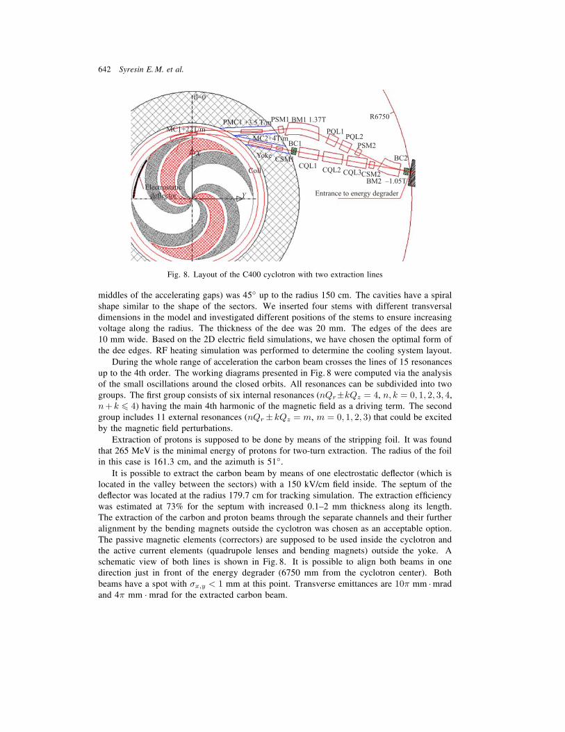
Fig. 8. Layout of the C400 cyclotron with two extraction lines
middles of the accelerating gaps) was 45◦ up to the radius 150 cm. The cavities have a spiralshape similar to the shape of the sectors. We inserted four stems with different transversaldimensions in the model and investigated different positions of the stems to ensure increasingvoltage along the radius. The thickness of the dee was 20 mm. The edges of the dees are10 mm wide. Based on the 2D electric ˇeld simulations, we have chosen the optimal form ofthe dee edges. RF heating simulation was performed to determine the cooling system layout.
During the whole range of acceleration the carbon beam crosses the lines of 15 resonancesup to the 4th order. The working diagrams presented in Fig. 8 were computed via the analysisof the small oscillations around the closed orbits. All resonances can be subdivided into twogroups. The ˇrst group consists of six internal resonances (nQr±kQz = 4, n, k = 0, 1, 2, 3, 4,n+ k � 4) having the main 4th harmonic of the magnetic ˇeld as a driving term. The secondgroup includes 11 external resonances (nQr ±kQz = m, m = 0, 1, 2, 3) that could be excitedby the magnetic ˇeld perturbations.
Extraction of protons is supposed to be done by means of the stripping foil. It was foundthat 265 MeV is the minimal energy of protons for two-turn extraction. The radius of the foilin this case is 161.3 cm, and the azimuth is 51◦.
It is possible to extract the carbon beam by means of one electrostatic deector (which islocated in the valley between the sectors) with a 150 kV/cm ˇeld inside. The septum of thedeector was located at the radius 179.7 cm for tracking simulation. The extraction efˇciencywas estimated at 73% for the septum with increased 0.1Ä2 mm thickness along its length.The extraction of the carbon and proton beams through the separate channels and their furtheralignment by the bending magnets outside the cyclotron was chosen as an acceptable option.The passive magnetic elements (correctors) are supposed to be used inside the cyclotron andthe active current elements (quadrupole lenses and bending magnets) outside the yoke. Aschematic view of both lines is shown in Fig. 8. It is possible to align both beams in onedirection just in front of the energy degrader (6750 mm from the cyclotron center). Bothbeams have a spot with σx,y < 1 mm at this point. Transverse emittances are 10π mm ·mradand 4π mm · mrad for the extracted carbon beam.

Development of Radiation Medicine at DLNP, JINR 643
DETECTORS FOR TOMOGRAPHY
Development of spectrometric computer tomographs (CT) may allow one to determinechemical composition of a substance together with the density, measured using traditionalCT. The main idea is to use peculiarities of X-ray absorbtion spectra near the K-edge lines,which are individual for different chemical elements and can be measured by the spectrometicdetectors. Using this additional information may greatly improve existing diagnostic tech-niques.
The gamma-ray energy in the spectral CT based on the JINRÄTSU GaAs pixel detec-tor [10] (Fig. 9) is determined by a special chip developed by Medipix collaboration [11]which is capable of registering gamma quanta in selected energy range, thus implementingcolor X-ray imaging.
The detecting systems of the spectrometric CT are based on the semiconducting het-erostructures. Together with spectrometric possibilities, the pixel detectors on the basis ofGaAs(Cr) have a high spatial resolution (∼ 100 μm), their sensitivity is an order of magnitudebetter as compared with Si detectors at a photon energy of 30Ä35 keV (Fig. 10).
Fig. 9. Spectrometric detector on the basis of GaAs(Cr) pixel sensor with 256× 256 channels of 50 μmresolution and Medipix chip
Fig. 10. Dependence of count ratios of GaAs(Cr) and Si detectors on the photon energy
644 Syresin E. M. et al.
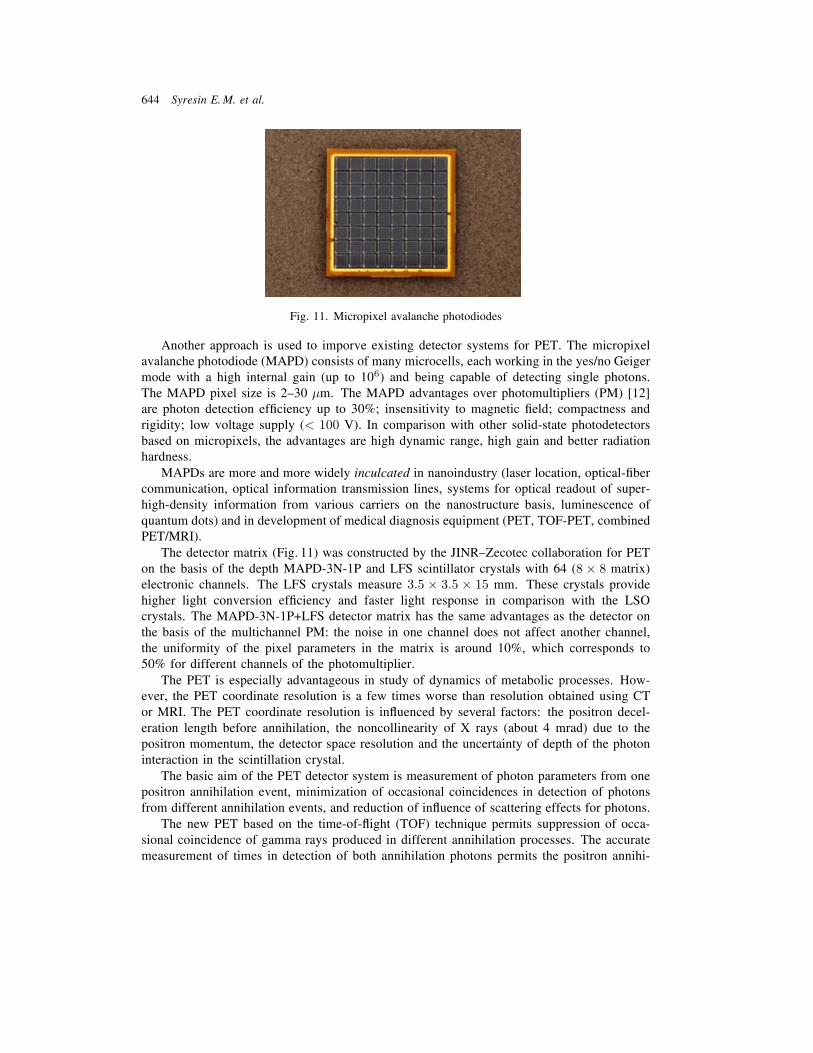
Fig. 11. Micropixel avalanche photodiodes
Another approach is used to imporve existing detector systems for PET. The micropixelavalanche photodiode (MAPD) consists of many microcells, each working in the yes/no Geigermode with a high internal gain (up to 106) and being capable of detecting single photons.The MAPD pixel size is 2Ä30 μm. The MAPD advantages over photomultipliers (PM) [12]are photon detection efˇciency up to 30%; insensitivity to magnetic ˇeld; compactness andrigidity; low voltage supply (< 100 V). In comparison with other solid-state photodetectorsbased on micropixels, the advantages are high dynamic range, high gain and better radiationhardness.
MAPDs are more and more widely inculcated in nanoindustry (laser location, optical-ˇbercommunication, optical information transmission lines, systems for optical readout of super-high-density information from various carriers on the nanostructure basis, luminescence ofquantum dots) and in development of medical diagnosis equipment (PET, TOF-PET, combinedPET/MRI).
The detector matrix (Fig. 11) was constructed by the JINRÄZecotec collaboration for PETon the basis of the depth MAPD-3N-1P and LFS scintillator crystals with 64 (8 × 8 matrix)electronic channels. The LFS crystals measure 3.5 × 3.5 × 15 mm. These crystals providehigher light conversion efˇciency and faster light response in comparison with the LSOcrystals. The MAPD-3N-1P+LFS detector matrix has the same advantages as the detector onthe basis of the multichannel PM: the noise in one channel does not affect another channel,the uniformity of the pixel parameters in the matrix is around 10%, which corresponds to50% for different channels of the photomultiplier.
The PET is especially advantageous in study of dynamics of metabolic processes. How-ever, the PET coordinate resolution is a few times worse than resolution obtained using CTor MRI. The PET coordinate resolution is inuenced by several factors: the positron decel-eration length before annihilation, the noncollinearity of X rays (about 4 mrad) due to thepositron momentum, the detector space resolution and the uncertainty of depth of the photoninteraction in the scintillation crystal.
The basic aim of the PET detector system is measurement of photon parameters from onepositron annihilation event, minimization of occasional coincidences in detection of photonsfrom different annihilation events, and reduction of inuence of scattering effects for photons.
The new PET based on the time-of-ight (TOF) technique permits suppression of occa-sional coincidence of gamma rays produced in different annihilation processes. The accuratemeasurement of times in detection of both annihilation photons permits the positron annihi-

Development of Radiation Medicine at DLNP, JINR 645
Fig. 12. Time resolution of two MAPD-3N-1P+LFS detectors for photo pick events
lation coordinate to be found. However, in present PET the time resolution corresponds to600Ä800 ps. It is determined by several factors: the scintillator and detector time response,the depth of photon interaction in the crystal, the light reection effects in the crystal, etc.However, the present PET time resolution of 600 ps essentially suppresses the occasionalevents in detection of two gamma rays produced in different positron annihilation events.The resolution time of the MAPD-3N-1P+LFS detector is about 400 ps (Fig. 12), a fac-tor of 1.5 times lower than in modern PET tomographs. It permits a factor of 1.5 lowermultiplicative reduction coefˇcient (noise level from occasional events).
A combined PET/MRI tomograph is under consideration in many research centers. Thekey problem in construction of a combined PET/MRI tomograph is associated with the PETphotodetector operating in a high MRT magnetic ˇeld. The photomultipliers used in thepresent PETs are not suitable for a combined PET/MRI because none of them can workin a high MRI magnetic ˇeld. Micropixel avalanche photodiodes (Fig. 11) allow making acombined PET/MRI tomograph.
CONCLUSION
We have reported numerous spin-offs for radiation medicine from technological devel-opment of accelerator techniques and detector systems performed at DLNP during the lastfew years. This applied activity is oriented towards the development of 3D conformal protontherapy, accelerator techniques for proton and carbon treatments and new types of detectorsystems for tomography.
The method of 3D conformal irradiation of deep-seated tumors with a proton beam wasimplemented at DLNP for the ˇrst time in Russia and is effectively used today for cancertreatment here. About 700 patients were treated by proton beams during the last 10 years.
Proton therapy hospital centers have become wide-spread in the world during the lastdecade. The medical cyclotron C235-V3 intended for hospital centers of proton therapy wasdeveloped by the JINRÄIBA collaboration. We plan to assemble this cyclotron at JINR in2011 and perform tests with the extracted proton beam in 2012. The ˇrst medical cyclotronC235-V3 will be installed in the Dimitrovgrad hospital center of proton therapy.
646 Syresin E. M. et al.
Carbon therapy is the most effective method to treat radioresistant tumors. A compactsuperconducting cyclotron C400 has been designed by the JINRÄIBA collaboration. Thiscyclotron will be used for radiotherapy with proton, helium and carbon ions. The constructionof C400 was started in 2010 within the framework of the Archarde project in Caen (France).
GaAs(Cr) pixel detectors developed at DLNP are promising for application in medicalimaging since they allow routine measurements of the energy of X-ray photons. Developmentof the spectrometric tomography based on such detectors can help in determining chemicalcomposition of a substance in addition to the density measured by traditional CT.
High time resolution has become important for TOF-PET where improved signal-to-noiseratio images, lower exposure rates and faster image reconstruction are required. A resolutionof about 400 ps (FWHM) was obtained in our measurements of LFSÄMAPD detectors.
PET/MRI will combine the good sensitivity of PET with the variety of contrast mech-anisms for anatomical and functional imaging of MRI. To enable PET inside MRI it issuitable to replace the photomultipliers used in PET by the MAPD which are insensitive tothe magnetic ˇeld of MRI.
Acknowledgements. The development of GaAs(Cr) semiconductor detectors was per-formed at support of the Russian Foundation for Basic Research, grant 09-99028-r-oˇ.
REFERENCES
1. Savchenko O. V. 40 Years of Proton Therapy on Synchrocyclotron and Phasotron of LNP, JINR //J. Med. Phys. 2007. No. 3Ä4.
2. Agapov A. V. et al. Technique of 3D Conformal Proton Therapy // Part. Nucl., Lett. 2005. V. 2,No. 6(129). P. 80Ä86.
3. Shvidky S. V. et al. Proton Three-Dimensional Radiotherapy and Radiosurgery of Intracranial Targetsin Dubna // Radioprotection. 2008. V. 43, No. 5. P. 7.
4. Karamysheva G. et al. Simulation of Beam Extraction from C235 Cyclotron for Proton Therapy //Part. Nucl., Lett. 2010. V. 7, No. 4.
5. Syresin E. M. Centers of Hadron Therapy on the Basis of Cyclotrons // RUPAC 08. Zelenograd,2008. P. 316.
6. Jongen Y. Design of a K = 1600 SC Cyclotron for Carbon Therapy // ECPM. Nice, 2006. P. 30.
7. Jongen Y. et al. Design Studies of the Compact Superconducting Cyclotron for Hadron Therapy //EPAC 06. Edinburgh, 2006. P. 1678.
8. Jongen Y. et al. IBA C400 Cyclotron Project for Hadron Therapy // Cyclotrons. Italy, 2007. P. 151.
9. Jongen Y. et al. Current Status of the IBA C400 Cyclotron Project for Hadron Therapy // EPAC 08.Venice, 2008. P. 1806.
10. Tlustos L., Chelkov G., Tolbanov O. Characterization of GaAs(Cr) Medipix2 Hybrid Pixel Detec-tors // Proc. of iWoRid. Prague, 2009.
11. Llopart X., Campbell M. First Test Measurements of a 64k Pixel Readout Chip Working in Single-Photon Counting Mode // Nucl. Instr. Meth. A. 2003. V. 509. P. 157Ä163.
12. Sadygov Z. et al. Three Advanced Designs of Micro-Pixel Avalanche Photodiodes: Their PresentStatus, Maximum Possibilities and Limitations // Nucl. Instr. Meth. A. 2006. V. 567. P. 70Ä73.
Received on November 1, 2010.