development of morphing aircraft structure using smp · polymer (smp) for making formable wing...
TRANSCRIPT

DEVELOPMENT OF MORPHING AIRCRAFT STRUCTURE USING SMP
THESIS
Soo-Chan Jee Captain, R.O.KAF
AFIT/GSE/ENV/10-M02
DEPARTMENT OF THE AIR FORCE AIR UNIVERSITY
AIR FORCE INSTITUTE OF TECHNOLOGY Wright-Patterson Air Force Base, Ohio
APPROVED FOR PUBLIC RELEASE; DISTRIBUTION UNLIMITED.

The views expressed in this thesis are those of the authors and do not reflect the official policy or position of the United States Air Force, Department of Defense, the U.S. Government, or any other defense organization.

AFIT/GSE/ENV/10-M02
DEVELOPMENT OF MORPHING AIRCRAFT STRUCTURE USING SMP
THESIS
Presented to the Faculty
Department of Engineering and Management
Graduate School of Engineering and Management
Air Force Institute of Technology
Air University
Air Education and Training Command
In Partial Fulfillment of the Requirements for the
Degree of Master of Science in Systems Engineering
Soo-Chan Jee
Captain, R.O.KAF
March 2010
APPROVED FOR PUBLIC RELEASE; DISTRIBUTION UNLIMITED.

AFIT/GSE/ENV/10-M02
DEVELOPMENT OF MORPHING AIRCRAFT STRUCTURE USING SMP
Soo-Chan Jee
Captain, R.O.KAF
Approved:
____________________________________ ________
Dr. Som R. Soni, (Chairman) Date
____________________________________ ________
Dr. Joseph W. Carl, (Member) Date
____________________________________ ________
Dr. David R. Jacques, (Member) Date

iv
AFIT/GSE/ENV/10-M02
Abstract
The U.S Air Force needs new aircraft which provide longer flight time, less fuel
consumption, better aerodynamics in order to perform Air Force missions successfully as the
mission environment changes rapidly. A morphing wing aircraft is considered as a potential new
aircraft for those missions. This thesis explores Shape Memory Polymer (SMP) properties test
results and its applicacation for morphing wing skin. Several SMP composite laminates were
considered for investigating shape changing characteristics required for morphing skin. The
braided composite preforms used in making SMP composites were explored in morphing wing
operating system based on the results of property tests. The system definition, life cycle of
system, user analysis, and some architecture for identifying systems effectively formed the basis
for the generic system engineering process presented. Further, this thesis explores initial
geometric deformability, recovery characteristics, material property estimates, and develops the
system using morphing material in order to present a concept for emerging morphing wing
aircraft as a potential future Air Force’s alternative. Based upon this research, the material
system considered here does not meet the morphing requirements for such aircraft.
v
Acknowledgments
I would like to express sincere appreciation to my faculty advisor, Dr. Som Soni, and Dr.
Joseph Carl, for their brilliant and insightful guidance and steadfast support throughout the
course of this thesis effort. I would also like to thank my academic advisor, Dr. Jacques, for his
great support during coursework. In addition, I would like to thank Mrs. Annette Robb, director
of IMSO in AFIT, for sacrifices supporting international officers. Finally I would like to thank
the USAF .I learned a lot from USAF and AFIT. I would like to apply everything I studied here
for development of R.O.KAF.
.
- Captain. Soo-chan Jee
vi
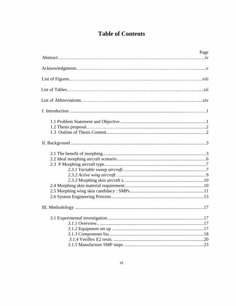
Table of Contents
Page Abstract………..………………………………………………………………………….iv
Acknowledgments………………………………………………….………………….......v
List of Figures……………………………………………..…………………………….viii
List of Tables………………………………………….…….……………...………….....xii
List of Abbreviations……………….…………………………………………………....xiv
I. Introduction .....................................................................................................………….1
1.1 Problem Statement and Objective ..........................................................................1 1.2 Thesis proposal………………….. .........................................................................2 1.3 Outline of Thesis Content .................................................................................….2
II. Background .....................................................................................................................3
2.1 The benefit of morphing .........................................................................................3 2.2 Ideal morphing aircraft scenario .............................................................................6 2.3 P Morphing aircraft type........................................................................................7
2.3.1 Variable sweep aircraft.. ......................................................................7 2.3.2 Active wing aircraft . ............................................................................9 2.3.3 Morphing skin aircraft s. ....................................................................10
2.4 Morphing skin material requirement ....................................................................10 2.5 Morphing wing skin candidacy : SMPs ................................................................11 2.6 System Engineering Process ................................................................................13
III. Methodology ...............................................................................................................17
3.1 Experimental investigation ...................................................................................17
3.1.1 Overview.. ..........................................................................................17 3.1.2 Equipment set up . ..............................................................................17 3.1.3 Componenet list. .................................................................................18 3.1.4 Veriflex E2 resin. ..............................................................................20 3.1.5 Manufacture SMP steps .....................................................................23
vii
Page
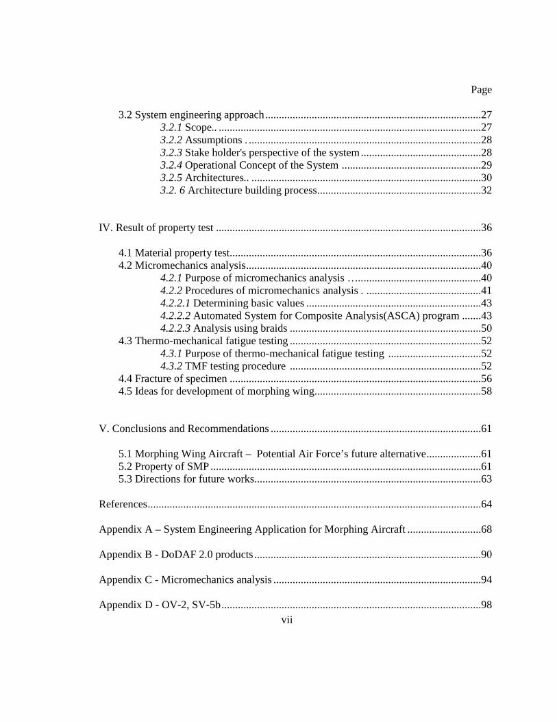
3.2 System engineering approach ...............................................................................27
3.2.1 Scope.. ................................................................................................27 3.2.2 Assumptions . .....................................................................................28 3.2.3 Stake holder's perspective of the system ............................................28 3.2.4 Operational Concept of the System ...................................................29 3.2.5 Architectures.. ....................................................................................30 3.2. 6 Architecture building process............................................................32
IV. Result of property test .................................................................................................36
4.1 Material property test............................................................................................36 4.2 Micromechanics analysis ......................................................................................40
4.2.1 Purpose of micromechanics analysis ….............................................40 4.2.2 Procedures of micromechanics analysis . ..........................................41 4.2.2.1 Determining basic values ................................................................43 4.2.2.2 Automated System for Composite Analysis(ASCA) program .......43 4.2.2.3 Analysis using braids ......................................................................50
4.3 Thermo-mechanical fatigue testing ......................................................................52 4.3.1 Purpose of thermo-mechanical fatigue testing ..................................52 4.3.2 TMF testing procedure ......................................................................52
4.4 Fracture of specimen ............................................................................................56 4.5 Ideas for development of morphing wing.............................................................58
V. Conclusions and Recommendations .............................................................................61
5.1 Morphing Wing Aircraft – Potential Air Force’s future alternative ....................61 5.2 Property of SMP ...................................................................................................61 5.3 Directions for future works...................................................................................63
References ..........................................................................................................................64
Appendix A – System Engineering Application for Morphing Aircraft ...........................68
Appendix B - DoDAF 2.0 products ...................................................................................90
Appendix C - Micromechanics analysis ............................................................................94
Appendix D - OV-2, SV-5b ...............................................................................................98
viii
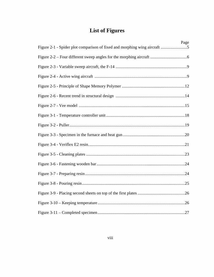
List of Figures
Page Figure 2-1 - Spider plot comparison of fixed and morphing wing aircraft .........................5
Figure 2-2 – Four different sweep angles for the morphing aircraft ...................................6
Figure 2-3 - Variable sweep aircraft, the F-14 ....................................................................9
Figure 2-4 - Active wing aircraft ........................................................................................9
Figure 2-5 - Principle of Shape Memory Polymer ............................................................12
Figure 2-6 - Recent trend in structural design ..................................................................14
Figure 2-7 - Vee model .....................................................................................................15
Figure 3-1 - Temperature controller unit ...........................................................................18
Figure 3-2 - Puller ..............................................................................................................19
Figure 3-3 - Specimen in the furnace and heat gun ...........................................................20
Figure 3-4 - Veriflex E2 resin. ...........................................................................................21
Figure 3-5 - Cleaning plates ..............................................................................................23
Figure 3-6 - Fastening wooden bar ....................................................................................24
Figure 3-7 - Preparing resin ...............................................................................................24
Figure 3-8 - Pouring resin ..................................................................................................25
Figure 3-9 - Placing second sheets on top of the first plates .............................................26
Figure 3-10 – Keeping temperature ...................................................................................26
Figure 3-11 – Completed specimen ...................................................................................27
ix
Page
Figure 3-12 - DoDAF Architecture products relationships ...............................................35
Figure 4-1 - Origin Specimen in the furnace .....................................................................37
Figure 4-2 - Changing color of specimen ..........................................................................37
Figure 4-3 - Heated specimen ............................................................................................38
Figure 4-4 - Soften specimen .............................................................................................38
Figure 4-5 - Deformed specimen .......................................................................................39
Figure 4-6 - Optical microscopic images of SMP composite specimen ...........................39
Figure 4-7 – Analyzing composites ...................................................................................40
Figure 4-8 - Specimen sample ...........................................................................................41
Figure 4-9 - Automated SMP analysis using EXCEL ......................................................42
Figure 4-10 - Specimen property .......................................................................................44
Figure 4-11 - Specimen orientation and stacking sequence ..............................................44
Figure 4-12 - Laminate effective engineering constants ...................................................45
Figure 4-13 - Stress components from free edge ...............................................................46
Figure 4-14 - Stress components at 0.01 inch ....................................................................47
Figure 4-15 - Stress components at 0.02 inch ....................................................................47
Figure 4-16 - Stress components at 0.03 inch ....................................................................48
Figure 4-17 - General information about the SMP composite using the Braids program 51
x
Page
Figure 4-18 - Young modulus of specimen ......................................................................51
Figure 4-19 - Original specimen .......................................................................................54
Figure 4-20 - Thermo-mechanical loaded specimen .........................................................54
Figure 4-21 - X-ray inspection of specimens ....................................................................55
Figure 4-22 - Fracture of Specimen ...................................................................................57
Figure 4-23 - Fracture of Specimen ...................................................................................57
Figure 4-24 - SMP composite having a heat tube ..............................................................59
Figure 4-25 – Heat tansferring method in the wing section ..............................................60
Figure A-1 - Life cycle of MWOS.....................................................................................70
Figure A-2 - Operational objective hierarchy ....................................................................79
Figure A-3 - MWOS OV-1 ................................................................................................82
Figure A-4 - OV-5 Node tree .............................................................................................84
Figure A-6 - AO architecture .............................................................................................85
Figure A-7 - OV-5 A0 architecture ...................................................................................87
Figure C-1 - Braids analysis of fiber angles ......................................................................95
Figure C-2 - Braids analysis of thickness ..........................................................................95
Figure C-3 - Braids analysis of Poisson's ratio ..................................................................96
Figure C-4 - Braids analysis of Shear modulus .................................................................96

xi
Page
Figure C-5 - Braids analysis of Young's modulus .............................................................97
Figure D-1 - MWOS OV-2 ................................................................................................98
Figure D-2 - MWOS SV-5b………………………………………………………. .........99
xii
List of Tables
Page Table 3-1 - Cured Material properties .........................................................................22
Table 4-1 - Table of specimen .....................................................................................61
Table A-1 – Description of various costs ....................................................................69
Table B-1 – DoDAF architecture products ..................................................................90

xiii
List of Graphs
Page Graph 4-1 - Interlaminar stress (σ-z) ...........................................................................49
Graph 4-2 - Interlaminar stress (γ-yz) .........................................................................49
Graph 4-3 - Interlaminar stress (γ-xz)………………………………………….....…50
Graph 4-4 - Graph of thermo mechanical load ...........................................................53
Graph C-1 - Stress plot of layer No.1 ..........................................................................94

xiv
List of Abbreviations
AF – Air Force
AFIT – Air Force Institute of Technology
AFRL – Air Force Research Laboratory
AOA – Angle of Attack
ASCA– Automated System for Composite Analysis
CLAP – Composite Laminate Analysis Program
CONOPS – Concepts of operations
DARPA – Defense Advanced Research Projects Agency
DoD – Department of Defense
DoDAF – Department of Defense Architecture Framework
FESAP – Free Edge Stress Analysis
MWOS–Morphing Wing Operating System
MWMS– Morphing Wing Mechanism System
RCS – Radar Cross Section
SEP - System Engineering Process
SMP – Shape Memory Polymer
USAF – United States Air Force
R.O.KAF – Republic of Korea Air Force
TST – Time Sensitive Target
TMF –Thermo-mechanical fatigue

1
DEVELOPMENT OF MORPHING AIRCRAFT STRUCTURE USING SMP
I. Introduction
1.1 Problem Statement and Objective
The way the United States Air Force uses aircraft needs to be changed. New targets have
emerged and new enemy’s strategies have been developed. As most people already know,
enemies make their targets smaller and hide them to prevent detection. We also face difficulty in
attacking those targets because of complexity and proliferation of air control in certain areas. In
this situation the aircraft need more time, information and energy to detect and attack targets. In
other words, the United States Air Force needs to make aircraft that provide flexibility and
versatility to deal with these kinds of targets in a cost effective manner [1]. These new changing
warfare environments require new concepts of aircraft in warfare. To meet the new requirements,
many scientists have researched many kinds of new aircraft. Among them, morphing aircraft is a
promising alternative. Generally, a morphing aircraft changes its external shape to adapt to a
changing mission environment during its flight. Research on morphing aircraft is popular and
proliferating all over the world. NASA, DARPA and other labs have already developed their
morphing aircraft test models and have been conducting different experiments on morphing
aircraft. To make morphing aircraft, we face several difficulties in transforming wings. There are
some transforming wings so far; however, we need wings that can change their shape with
various motions and agility in a cost effective manner. This thesis deals with the Shape Memory

2
Polymer (SMP) for making formable wing skin. SMPs are promising materials with properties
offering literate stiffness and geometric changes at temperature changes. Thus, SMP can be
deformed or keep its shape as temperature changes. Using this property this thesis deals with
challenges involved in making the morphing aircraft wing skin. We integrated the effect of
retaining shape of the polymer with cyclic deformation under thermo mechanical loading. At
about 50 cycles, we observed that plastic deformation has taken place. This shows that the
material considered does not meet the morphing requirements of an aircraft.
1.2 Thesis Proposal
AFRL and DARPA have sponsored this research leading to a morphing aircraft mechanism.
They have already made enormous progress in this technology; however, there is still a lot more
to be done in creating a morphing wing and transforming wing system. This situation drives this
thesis proposal because AFIT laboratory facilities, faculty, and students can help explore other
more effective alternatives from mechanical based design to material based (e.g. SMP based)
designs.
1.3 Outline of Thesis Content
Chapter 2 deals with background consisting of approaches to make morphing wings and
create appropriate material for developing morphing wings. This background lays down the
foundation in chapter 3 for experimenting with SMP laminates. Chapter 4 includes results of
material experiments. Finally, chapter 5 includes conclusions and recommendations based on the
research conducted during thesis study.
3
II. Background
This section introduces morphing and SMP materials with a brief introduction to the
morphing wing and SMP. The section includes system engineering review.
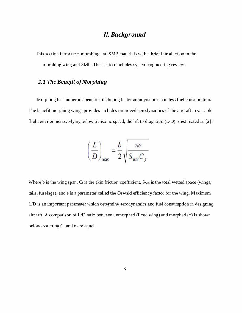
2.1 The Benefit of Morphing
Morphing has numerous benefits, including better aerodynamics and less fuel consumption.
The benefit morphing wings provides includes improved aerodynamics of the aircraft in variable
flight environments. Flying below transonic speed, the lift to drag ratio (L/D) is estimated as [2] :
Where b is the wing span, Cf is the skin friction coefficient, Swet is the total wetted space (wings,
tails, fuselage), and e is a parameter called the Oswald efficiency factor for the wing. Maximum
L/D is an important parameter which determine aerodynamics and fuel consumption in designing
aircraft, A comparison of L/D ratio between unmorphed (fixed wing) and morphed (*) is shown
below assuming Cf and e are equal.
4
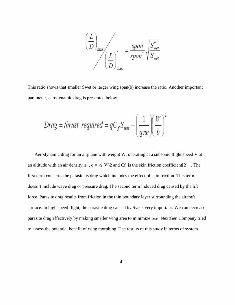
This ratio shows that smaller Swet or larger wing span(b) increase the ratio. Another important
parameter, aerodynamic drag is presented below.
Aerodynamic drag for an airplane with weight W, operating at a subsonic flight speed V at
an altitude with an air density is . q = ½ V^2 and Cf is the skin friction coefficient[2] . The
first term concerns the parasite is drag which includes the effect of skin friction. This term
doesn’t include wave drag or pressure drag. The second term induced drag caused by the lift
force. Parasite drag results from friction in the thin boundary layer surrounding the aircraft
surface. In high speed flight, the parasite drag caused by Swet is very important. We can decrease
parasite drag effectively by making smaller wing area to minimize Swet. NextGen Company tried
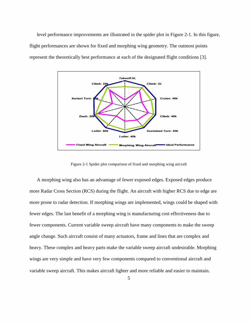
to assess the potential benefit of wing morphing. The results of this study in terms of system-
5
level performance improvements are illustrated in the spider plot in Figure 2-1. In this figure,
flight performances are shown for fixed and morphing wing geometry. The outmost points
represent the theoretically best performance at each of the designated flight conditions [3].
Figure 2-1 Spider plot comparison of fixed and morphing wing aircraft
A morphing wing also has an advantage of fewer exposed edges. Exposed edges produce
more Radar Cross Section (RCS) during the flight. An aircraft with higher RCS due to edge are
more prone to radar detection. If morphing wings are implemented, wings could be shaped with
fewer edges. The last benefit of a morphing wing is manufacturing cost effectiveness due to
fewer components. Current variable sweep aircraft have many components to make the sweep
angle change. Such aircraft consist of many actuators, frame and lines that are complex and
heavy. These complex and heavy parts make the variable sweep aircraft undesirable. Morphing
wings are very simple and have very few components compared to conventional aircraft and
variable sweep aircraft. This makes aircraft lighter and more reliable and easier to maintain.

6
2.2 Ideal Morphing Aircraft Scenario
Figure 2-2 Four different sweep angles for the morphing aircraft
a. Take off
Morphing aircraft find the most optimal lift coefficient over drag coefficient ratio(CL/CD)
for takeoff to get the shortest distance for takeoff. After takeoff, the aircraft sets up the wing to
climb up to 30,000 feet with changing Angle of Attack (AOA) and wing shape.
b. Cruise
After climbing up to 30,000 feet, morphing aircraft change their wing again. To get the
effective fuel consumption and low drag for cruising long distance, morphing wings transform to
longer span and smaller surface to get high CL/CD ratio.

7
c. Loiter
The morphing aircraft loiter to get enemy information and detect the enemy. Morphing
aircraft maintain longer wing span and a larger surface to save fuel consumption during the
loiter. Morphing aircraft can spend more time loitering because they can change wing shape in a
fuel effective manner.
d. Dash
During loitering the morphing aircraft transform their wings with more sweep back angle to
dash in order to get high speed and handling control.
2.3 Morphing Aircraft Type
This section briefly reviews the history and current effort in the development of morphing air
craft, variable sweep angle aircraft, active (folding) wing aircraft and morphing skin air craft.
These aircrafts are tested and some of them performed missions in the wars.
2.3.1 Variable sweep air craft
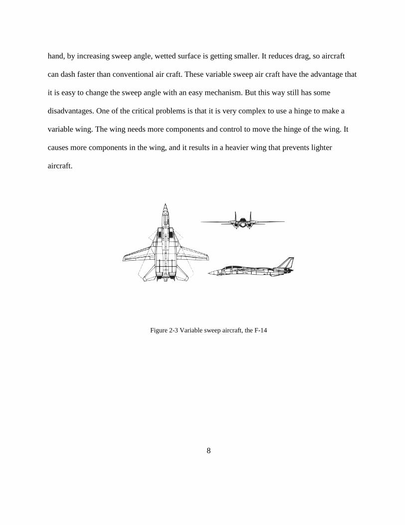
A well known morphing air craft is the F-14, which has variable sweep wings (Figure 2-3).
It has performed multi-role successfully. The variable sweep wing or swing wing uses kinetic
and mechanical principles to change sweep angle in the wing. By decreasing sweep angle, wetted
surface becomes bigger. It produces more lift force with less fuel consumption. On the other
8
hand, by increasing sweep angle, wetted surface is getting smaller. It reduces drag, so aircraft
can dash faster than conventional air craft. These variable sweep air craft have the advantage that
it is easy to change the sweep angle with an easy mechanism. But this way still has some
disadvantages. One of the critical problems is that it is very complex to use a hinge to make a
variable wing. The wing needs more components and control to move the hinge of the wing. It
causes more components in the wing, and it results in a heavier wing that prevents lighter
aircraft.
Figure 2-3 Variable sweep aircraft, the F-14

9
2.3.2 Active wing air craft
Another method is folding wing. Many scientists devised wings that twist or fold during
flight. This method is still researched as a promising approach. Folding the wing uses the
actuator or active skin material. These aircraft fold their wing to speed up during the flight
(Figure 2-4). The effect is like a larger sweep angle. On the other hand, morphing air craft unfold
their wings when they need more lift to minimize fuel consumption. This expands wetted area to
get more lift. However, this way can only transform its wing through a restricted shape that is
implemented by a mechanical actuator. Active wing aircraft lack variability in changing the wing
platform.
Figure 2-4 Active wing aircraft
10
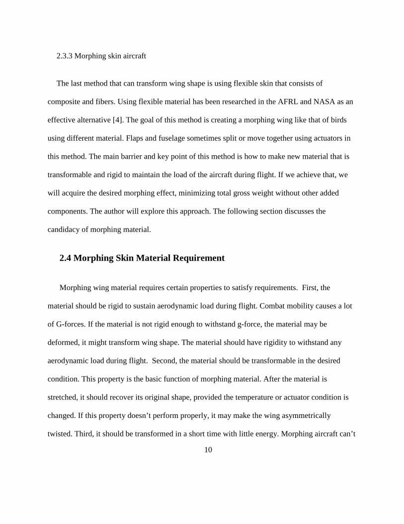
2.3.3 Morphing skin aircraft
The last method that can transform wing shape is using flexible skin that consists of
composite and fibers. Using flexible material has been researched in the AFRL and NASA as an
effective alternative [4]. The goal of this method is creating a morphing wing like that of birds
using different material. Flaps and fuselage sometimes split or move together using actuators in
this method. The main barrier and key point of this method is how to make new material that is
transformable and rigid to maintain the load of the aircraft during flight. If we achieve that, we
will acquire the desired morphing effect, minimizing total gross weight without other added
components. The author will explore this approach. The following section discusses the
candidacy of morphing material.
2.4 Morphing Skin Material Requirement
Morphing wing material requires certain properties to satisfy requirements. First, the
material should be rigid to sustain aerodynamic load during flight. Combat mobility causes a lot
of G-forces. If the material is not rigid enough to withstand g-force, the material may be
deformed, it might transform wing shape. The material should have rigidity to withstand any
aerodynamic load during flight. Second, the material should be transformable in the desired
condition. This property is the basic function of morphing material. After the material is
stretched, it should recover its original shape, provided the temperature or actuator condition is
changed. If this property doesn’t perform properly, it may make the wing asymmetrically
twisted. Third, it should be transformed in a short time with little energy. Morphing aircraft can’t
11
wait for a long time to transform wings, and can’t spend a lot of energy only for changing wing
shape. Material should be changed in shorter time using an actuator to keep these properties.
Fourth, material should withstand large in-plane and shear strains. Morphing wings are apt to
produce a lot of strain because of transition, which may cause a lot of cracks. This could cause
catastrophic failure. Thus, to keep the reliability of the wing, the material should sustain strains
[4].
2.5 Morphing Wing Skin Candidacy: SMPs
SMP are an emerging class of active polymers that have dual-shape capability. They can
transform their shape in a pre-programmed way from shape A to shape B when the material is
exposed to an appropriate stimulus.
2.5.1 General concept of shape-memory polymers
The shape-memory effect is not an intrinsic property. Polymers do not transform by
themselves. This means that shape memory results from a combination of polymer morphology
and specific processing. By conventional processing, for example(figure 4) extruding or injection
molding, the polymer is formed into its initial, permanent shape B. Afterwards, in a process
called programming, the polymer is deformed and fixed into the temporary shape A. Under
application of an external stimulus, the polymer recovers its initial shape B. This cycle of
programming and recovery can be repeated several times, with different shapes in subsequent
cycles. In comparison with metallic shape-memory alloys, this cycle of programming and

12
recovery can take place in a much shorter time interval and polymers allow a much higher
deformation rate between shapes A and B [6].
Figure 2-5 Principle of Shape Memory Polymer
The polymer network consists of molecular switches and net points. The net points determine
the permanent shape of the polymer network and physical characteristics. If the working
temperature is higher than Ttrans then the switching domains are flexible, resulting in an elastic
behavior of the polymer network above Ttrans. If the sample has been previously deformed by
application of an external stress, it snaps back into its initial shape once the external stress is
released. During the course of this study, we concentrated on investigating the shape changing
capability of SMP composite as a function of thermo mechanical load. We have observed that
the SMP composite loses its capability of recovering its original shape at about 50 cycles. Thus
this material is not suitable for morphing wing aircraft application. It may be useful for
munitions application where lesser number of morphing cycles may be required to meet the
mission objective.
13
2.6 Systems Engineering Process
Many people define system engineering as an interdisciplinary field of engineering that
focuses on how complex engineering projects should be designed and managed. Issues such as
logistics, the coordination of different teams, and automatic control of machinery become more
difficult when dealing with large, complex projects. Systems engineering deals with work-
processes and tools to handle such projects, and it overlaps with both technical and human-
centered disciplines such as reliability maintainability, logistics support and human factors [7].
In this thesis the author will apply system engineering to define an appropriate wing
morphing system. The reason why system engineering is useful can be explained using the
following Figure 2-6 [8]. Many materials and control methods are advancing rapidly. Some of
them are tested and used in other structures. New materials often are different from conventional
materials in that they have more complex properties with which to deal. As a candidate for
morphing wing material, SMPs has very complex properties as temperature changes. These new
complex challenges create a rising need for an interdisciplinary system approach. We have to
involve other engineering approaches such as mechanical and industrial engineering. We also
involve new failure modes and strategies for managing them. In these kinds of work, System
Engineering Process (SEP) will help us analyze processes and integrate all the solutions for the
system.

14
Figure 2-6 Recent trend in structural design and a way ahead for overcoming the challenges
In system engineering the stake-holders of the system influence the objectives of the system
against which the success of the system is measured. These objectives usually include cost,
schedule, and technical performance. In applying system engineering, the system engineer has to
resolve conflicting objectives. To apply the interdisciplinary approach for the required system
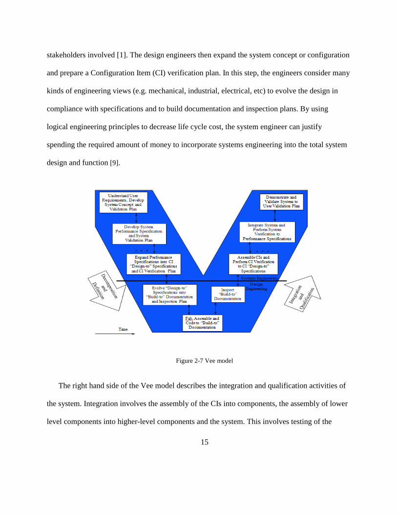
design, a systems engineering approach is depicted by the Vee model (Figure 2-7). The system
engineering Vee model starts with understanding the stakeholder requirements to develop the
system concept and the validation plan. In this step the system engineer decomposes user’s
requirements and develops the system concept. The engineer considers many engineering views
from many stakeholders and thinks about an overall system concept. Once this first step is
accomplished, the engineer starts to develop the system performance specification, system
requirements, and the system verification and validation plan. In this step, engineers have to
facilitate the design and system tradeoffs due to the complexity of the issues and the multitude of
15
stakeholders involved [1]. The design engineers then expand the system concept or configuration
and prepare a Configuration Item (CI) verification plan. In this step, the engineers consider many
kinds of engineering views (e.g. mechanical, industrial, electrical, etc) to evolve the design in
compliance with specifications and to build documentation and inspection plans. By using
logical engineering principles to decrease life cycle cost, the system engineer can justify
spending the required amount of money to incorporate systems engineering into the total system
design and function [9].
Figure 2-7 Vee model
The right hand side of the Vee model describes the integration and qualification activities of
the system. Integration involves the assembly of the CIs into components, the assembly of lower
level components into higher-level components and the system. This involves testing of the
16
newly assembled system components to determine whether the assembled components will meet
the set of requirements or specifications that the design phase had established for that
component. This qualification is called verification. Verification addresses the question; did we
build the system right? Once the system is verified against the system requirements, the system
must be validated. Validation answers the questions: Did we build the right system? Or does the
system meet the user requirements? After validation, the stakeholders decide whether the system
is acceptable or not.
In analyzing SMP properties and implementing a morphing wing control system, Vee model
is the most appropriate. The Vee model provides benefits for the planning and realization of this
system:
(1) The Vee model is considered a standardized process model.
(2) Management of system risk: The Vee model improves project transparency and
project control by specifying standardized approaches and describing the
corresponding results and responsible roles. It permits an early recognition of
planning deviations and risks and improves process management.
(3) Improvement of communication between all stakeholders: The standardized and
uniform description of all relevant elements and terms is the basis for the mutual
understanding among all stakeholders. Thus, the Vee model can reduce frictional
loss between user, acquirer, supplier and developer [10].
17
III. Methodology
The morphing aircraft wing requires complex sub systems. The thesis deals with the
mechanics of materials associated with shape changing aspects. These materials are the most
important part in the development of morphing aircraft wings. Composites made with shape
memory polymer, matrix and bi-axial braids and fibers are used. Further details follow:
3.1 Experimental Investigation
3.1.1 Overview
The material used to fabricate all test specimens for this investigation is Shape Memory
Polymer using the Veriflex E2 resin system. Lay-up and manufacturing was performed at CRG
Industries in Beavercreek, OH. Specimens are prepared by CRG industries. Deformation tests
were performed in the AFIT system engineering laboratory.
3.1.2 Equipment set up
The testing system is designed to provide an affordable and easy to use platform for
mechanical testing of shape memory polymers and shape memory polymer matrix
composites. The system is designed to apply a maximum of 500 lbs tension loading to a
wide range of specimen geometries and dimensions. The heating unit is made out of a
transparent acrylic box and heat is applied to the specimen using forced hot air generated
using an industrial heat gun. The temperature in the box is digitally regulated using a high
18
accuracy temperature controller and a phase-fired power supply. The testing frame has a
built in load cell that can measure loads up to 1000 lbs. It can be connected to a computer
through a DAQ (Data acquisition) card which works with data acquisition software such
as Labview.
3.1.3 Component list
a. Metallic frame
The frame is made out of 14 gauges; 1.5” x 1.5” galvanized steel slotted angle
material and is designed to withstand a maximum load of 500 lbs.
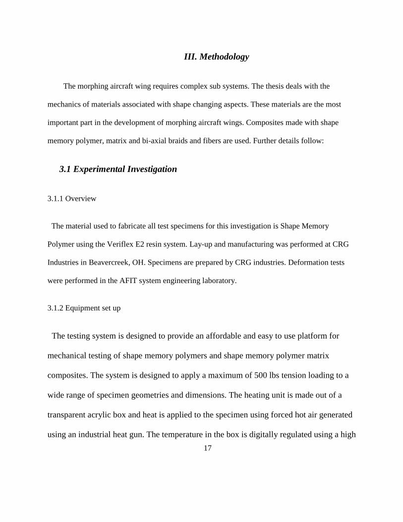
b. Temperature controller unit
The temperature controller unit runs on 110V / 60Hz AC power. On/off toggle
switches on the front of the box control the functions (Figure 3-1).
Figure 3-1 Temperature controller unit

19
c. Ratcheting puller for loading
Figure 3-2 Puller
The ratcheting puller used in the test frame is model 4LY45 from Grainger Inc
(Figure 3-2).
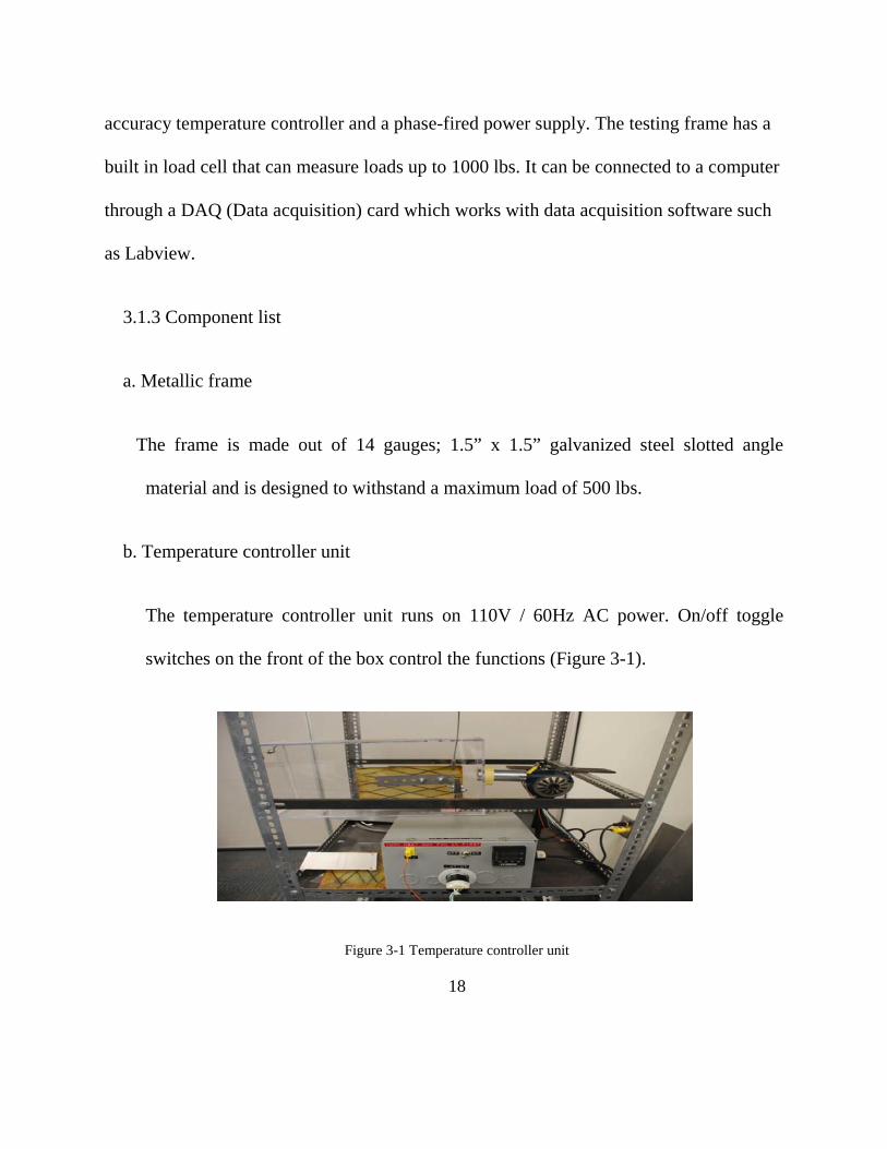
d. Heating unit/furnace
The heating unit consists of a modified Bosch 1942 industrial heating gun and
transparent acrylic box to house the specimen and retain hot air for heating the specimen.
The heat gun is modified to separate the input power for the fan and the heating element.
The fan is powered through a 110V wall outlet. It is highly recommended to turn the fan
on before connecting the heating element to prevent burning the heating element out from
excessive heat without circulating air (Figure 3-3).
20
Figure 3-3 Specimen in the furnace and heat gun
e. Load cell
The load cell is constructed of stainless steel and can measure loads up to 1000 lbs.
The load cell is linearly calibrated to output 21mV at 1000 lbs.
3.1.4 Veriflex E2 resin
Cured Veriflex E2 has unique “shape memory” properties. When heated above its glass
transition temperature (Tg), Veriflex E2 (figure 3-4) changes from a rigid plastic to an elastic
rubber. In this elastic state it can be twisted, pulled, bent, and stretched, reaching over 100%
elongation. If cooled while constrained in this new shape, the polymer hardens and can maintain
its deformed configuration indefinitely. When heated above Tg this polymer returns to the shape
in which it was cured. This process can be repeated indefinitely without loss of the memory

21
shape or degradation of the material. Veriflex E2 resin is engineered with a glass transition
temperature (Tg) of 217 ºF(103ºC). The uncured resin has a low viscosity that makes it easy for
processing composite fabrication. The SMP composites used by Veriflex E2 have common
features and benefits. These have unique shape memory properties, and they can be deformed
and recover repeatedly. This property makes them transform reversibly from rigid polymer to
soft elastomeric. It also provides over 100% elongation in its elastic state with increased
durability [11].
Figure 3-4 Veriflex E2 resin
• Curing conditions :
Veriflex E2 (Table 3-1) should be cured in a closed system mold. Here is a suggested
cure cycle:

22
- Ramp from room temperature to 257 ºF over a half hour
- Soak at 257 ºF for 4 hours
- Ramp form 257 ºF to 302 ºF over a half hour
- Soak at 302 ºF for 4 hours
Table 3- 1 Cured material
properties
23
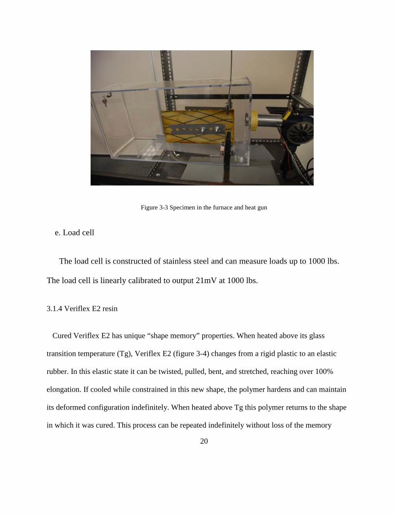
3.1.5 Manufacture SMP steps
At first, we got two clean plates and put mold release on the surface of them. We wiped the
mold release with long strokes over the entire surface using a paper towel, going over it several
times to ensure the entire plate had been covered (Figure 3-5). Then, we let the plates dry for 5
minutes before continuing
Figure 3-5 Cleaning plates
1. Cut a length of wooden bar to match the length of the specimen. Bar should be long
enough to go around the edges of mold. We have to fasten the wooden bars in desired
positions with tape or molding bond. The bars will keep the resin from falling or slipping
(Figure 3-6).
24
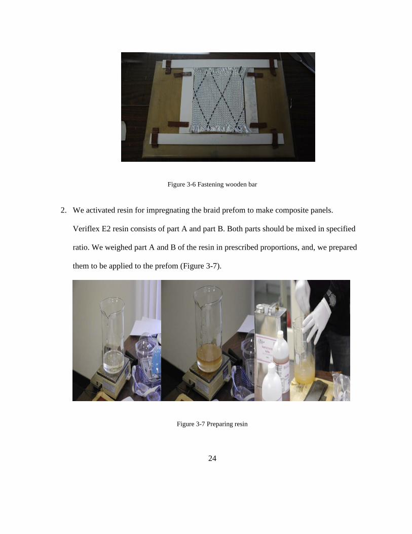
Figure 3-6 Fastening wooden bar
2. We activated resin for impregnating the braid prefom to make composite panels.
Veriflex E2 resin consists of part A and part B. Both parts should be mixed in specified
ratio. We weighed part A and B of the resin in prescribed proportions, and, we prepared
them to be applied to the prefom (Figure 3-7).
Figure 3-7 Preparing resin
25
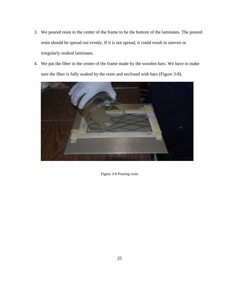
3. We poured resin in the center of the frame to be the bottom of the laminates. The poured
resin should be spread out evenly. If it is not spread, it could result in uneven or
irregularly soaked laminates.
4. We put the fiber in the center of the frame made by the wooden bars. We have to make
sure the fiber is fully soaked by the resin and enclosed with bars (Figure 3-8).
Figure 3-8 Pouring resin

26
5. Then we placed the second sheet on top of the first on which we already made the frame
and soaked the fiber (Figure 3-9).
Figure 3-9 Placing second sheets on top of the first plates
6. We used a vacuum plastic bag to prevent external contaminants. We kept the vacuum
state in the plastic bag.
7. We placed the plates on the temperature 254 ºF for 10 hours (Figure 3-10).
Figure 3-10 Keeping temperature
27
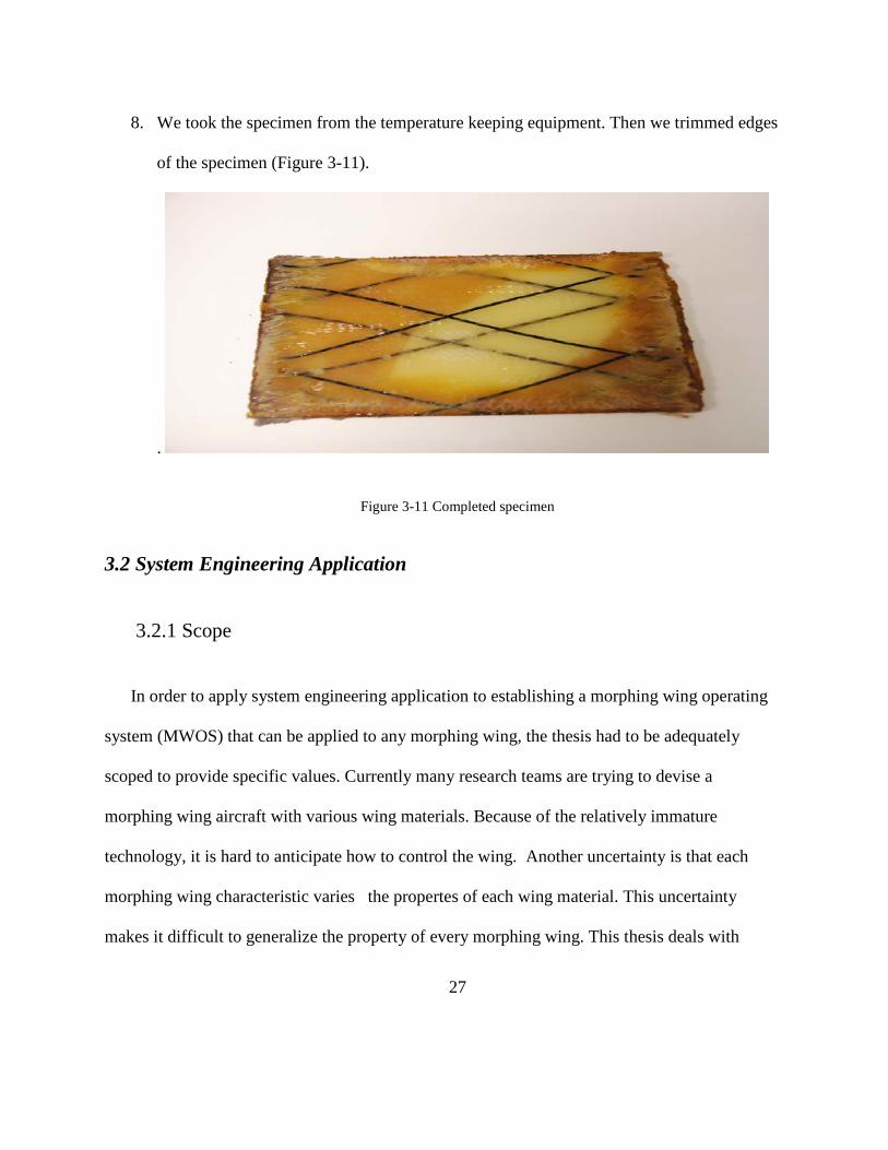
8. We took the specimen from the temperature keeping equipment. Then we trimmed edges
of the specimen (Figure 3-11).
.
Figure 3-11 Completed specimen
3.2 System Engineering Application
3.2.1 Scope
In order to apply system engineering application to establishing a morphing wing operating
system (MWOS) that can be applied to any morphing wing, the thesis had to be adequately
scoped to provide specific values. Currently many research teams are trying to devise a
morphing wing aircraft with various wing materials. Because of the relatively immature
technology, it is hard to anticipate how to control the wing. Another uncertainty is that each
morphing wing characteristic varies the propertes of each wing material. This uncertainty
makes it difficult to generalize the property of every morphing wing. This thesis deals with

28
conceptual system engineering application of morphing wing operating system. All the results
from this application will be in appendix A
3.2.2 Assumptions
There are a number of assumptions that were required to develop the system engineering
approach to develop MWMS (Morphing Wing Operating System). They are:
(1) SMP has been made appropriately and will show reliable shape changing property in
every test;
(2) Morphing will be operated instantly during flight;
(3) The actuator can be developed to exactly load the wing material; and
(4) The morphing wing section has similar functions and properties to a conventional
wing section.
3.2.3 Stakeholder’s Perspective of the System
Identifying the stakeholders is a very important step at the beginning of the conceptual design
of a system using the system engineering methodology. Stakeholders can be the bill payer, the
developers, the operators, the trainers among others. We need to identify all the stakeholders
who are involved with this system under development in order to communicate with them. This
is an important step for a system engineer to reflect the requirement from the stakeholders and
implement them. Identifying stakeholders might be difficult in some cases like this: The system
domain is so large that it is impossible to identify all the stakeholders. In this thesis, the author
29
will restrict attention to stakeholders who are involved with MWOS closely. The author will
describe the MWOS system and its life cycle phases to identify the stakeholders for each phase.
Potential stakeholders can be identified in each phase without any omission. The final product
will include stakeholders in each phase.
3.2.4 Operational Concept of the System
An operational concept describes how a system will be utilized. Its interactions with external
systems and the main functions of the system are included in that description. The author tried to
represent how to use the system and the needs it is going to serve with various stakeholders. It
will include a vision of the system and mission requirements mentioned by the stakeholders
using informal language.
This thesis creates the operational concept using two different ways. The first way produces a
set of scenarios. These scenarios have both inputs and outputs to the system. The view of
stakeholders about the production, use and maintenance of the system is shown in each scenario.
The second way to establish the operational concept is to monitor similar existing aircraft wing
operating systems. There are a lot of wings currently being used in various airplanes. They are
made of many kinds of composites and alloys. Various wings have different operating systems
depending on the material properties. For example, a wing made of lighter composite can be
light and easy to control. However, it is weak in sustaining environmental effects such as hail or
foreign objects. Thus it needs to be controlled in different ways compared to other wings. This

30
thesis referred to a lot of different wings currently existing in various airplanes. These references
helped to produce an operational concept of the system.
3.2.5 Architectures
System engineers have the tools to understand and deal with complex system interactions. It is
the architecture that provides clarity and simplifies complex systems. Architecture in system
engineering means the formal representation used to display information about a system in a
comprehensive way that facilitates decision making. Architecture also plays an important role in
communicating between developers and stakeholders. There are a lot of architecture frameworks
being used currently. Each architecture frame has its own purpose and properties. Fortunately,
the DoD has its own architecture framework. It is the DoDAF (Department of Defense
Architecture Framework), which is widely used in many system designs for the Air Force [12].
3.2.5.1 DoD architecture framework
DoDAF version 2.0 was signed on May 2009. This updated DoDAF serves as the overarching,
comprehensive framework and conceptual model enabling the development of architectures to
facilitate the ability of Department of Defense managers at all levels to make key decisions more
effectively through organized information sharing across the Department, Joint capability areas,
Mission, Component, and Program boundaries[12]. DoDAF 2.0 has multiple viewpoints
compared to DoDAF 1.5. DoDAF 1.5 has only three views – The operational views, the
system/service views and the technical views. DoD 2.0 includes new views – capability view,
standards views, data/info views, service views, projects [12].
31
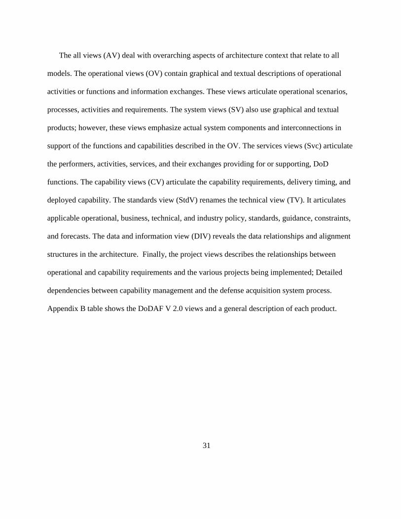
The all views (AV) deal with overarching aspects of architecture context that relate to all
models. The operational views (OV) contain graphical and textual descriptions of operational
activities or functions and information exchanges. These views articulate operational scenarios,
processes, activities and requirements. The system views (SV) also use graphical and textual
products; however, these views emphasize actual system components and interconnections in
support of the functions and capabilities described in the OV. The services views (Svc) articulate
the performers, activities, services, and their exchanges providing for or supporting, DoD
functions. The capability views (CV) articulate the capability requirements, delivery timing, and
deployed capability. The standards view (StdV) renames the technical view (TV). It articulates
applicable operational, business, technical, and industry policy, standards, guidance, constraints,
and forecasts. The data and information view (DIV) reveals the data relationships and alignment
structures in the architecture. Finally, the project views describes the relationships between
operational and capability requirements and the various projects being implemented; Detailed
dependencies between capability management and the defense acquisition system process.
Appendix B table shows the DoDAF V 2.0 views and a general description of each product.
32
3.2.6 Architecture Building Process
The author followed several steps for creating architecture as learned through system
engineering classes.
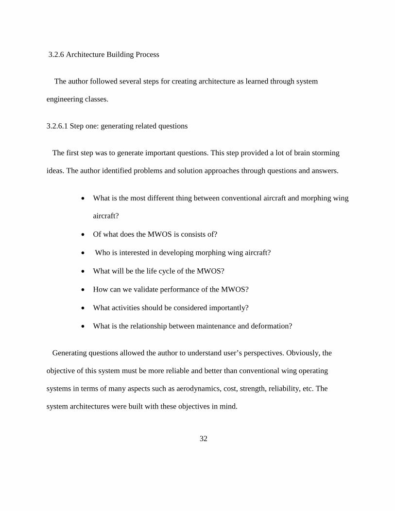
3.2.6.1 Step one: generating related questions
The first step was to generate important questions. This step provided a lot of brain storming
ideas. The author identified problems and solution approaches through questions and answers.
• What is the most different thing between conventional aircraft and morphing wing
aircraft?
• Of what does the MWOS is consists of?
• Who is interested in developing morphing wing aircraft?
• What will be the life cycle of the MWOS?
• How can we validate performance of the MWOS?
• What activities should be considered importantly?
• What is the relationship between maintenance and deformation?
Generating questions allowed the author to understand user’s perspectives. Obviously, the
objective of this system must be more reliable and better than conventional wing operating
systems in terms of many aspects such as aerodynamics, cost, strength, reliability, etc. The
system architectures were built with these objectives in mind.

33
3.2.6.2 Step two: determining the architecture description scope, and context with any
assumption.
As described above the architecture scope was constrained to the morphing wing made of
SMP. It also described many properties of wing control systems in life cycle terms. The
morphing wing material system also dealt with the following assumptions.
(1) SMP has been made appropriately.
(2) Morphing will be operated instantly during flight.
(3) The actuator can be developed to exactly load the wing section.
(4) The morphing wing section has similar function and properties to conventional wing
sections.
The level of detail in this architecture was left intentionally broad because morphing wings
are currently being developed. Moreover, the architecture was quite easily affected by properties
of the wing material. These limiting factors made it impossible to go deeper into defining
detailed system architectures.
3.2.6.3 Step three: determining what information the architecture description needs to capture
There was a lot of information related to this architecture. The author generated a lot of
candidate architectures through articles and library data. How to organize them is an important
role of a system engineer. Step three makes sure that the information contained in the
architecture is relevant and correlates with the information collected from the previous steps.

34
According to the DoDAF description, “if pertinent information is omitted, the architecture
description may not be useful; if unnecessary information is included, the architecture effort may
prove infeasible given the time and resources available, or the description may be confusing and
cluttered with details that are superfluous to the issues at hand[12].
The author investigated similar architectures that show many kinds of aircraft systems, control
systems and flight control systems. Some of them were effective and became the backbone of the
thesis. However, it was difficult to get sufficient data to show properties of future morphing wing
because SMP is a relatively new material.
3.2.6.4 Step four: determining the products to be built
DoDAF has many architecture products to choose from depending on the needs and
preferences of the architecture. After discussion with advisors, the author decided that the goal of
architecture in this thesis is to define and identify possible system requirements and estimate the
interaction and function of MWOS. Thus, the author concluded that architecture products should
be useful for showing this. DoDAF suggests the following products for integrated architecture:
AV-1, AV-2, OV-1, OV-2, OV-5, SV-1, SV-5, and TV-1. All the architecture products will be
presented in appendix A.
3.2.6.5 Steps five and six: gathering the architecture data and using the architecture description
for its intended purpose
The last two steps for building architecture are applying architecture products. Step five is
gathering the architecture data and building the requisite products. Step six is using the
35
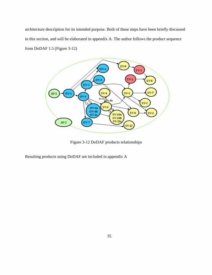
architecture description for its intended purpose. Both of these steps have been briefly discussed
in this section, and will be elaborated in appendix A. The author follows the product sequence
from DoDAF 1.5 (Figure 3-12)
Figure 3-12 DoDAF products relationships
Resulting products using DoDAF are included in appendix A
36
IV. Result of Property Test
There are many attempts to develop morphing wing aircraft [3].The present work is an
attempt to understand the response characteristics of available SMP composites. Since morphing
wing structure needs to demonstrate repeated shape change in flight, an attempt was made to
understand the effect of cyclic thermal and mechanical loadings on response characteristics of
SMP composites. For that purpose, we used both analytical and experimental approaches. This
chapter shows the results of preliminary material property tests and system engineering
application using material properties data.
4.1 Material Property Test
The author selected a black colored specimen to monitor the process of how the SMP softens at
glass transition temperature, Tg. As the specimen is heated, it changes its color because resin in
the SMP is softening as it is heated. With the heat transfer through the specimen, the white part
(resin is activating) increases its area in the black specimen. The author applied tensile force in
an axial direction with the puller after the SMP specimen softens. The specimen was deformed in
the axial direction, as desired. Microscopically, the specimen consisted of fiber and resin, the
polymer chains can undergo rotational conformational changes, allowing the polymer chains to
be uniaxially strained. As the material is strained, the alignment of the chains increases, which
increases the stored energy in the material as the configurational entropy of the chain decreases.
This energy is subsequently locked into the polymer chains when the material is cooled below
Tg and the chains are restricted from freely rotating via interactions with their neighbors. When
37
the polymer is reheated above Tg without constraint, an increase of entropy serves as a driving
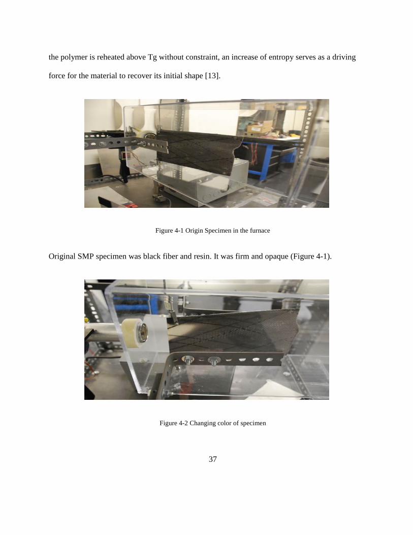
force for the material to recover its initial shape [13].
Figure 4-1 Origin Specimen in the furnace
Original SMP specimen was black fiber and resin. It was firm and opaque (Figure 4-1).
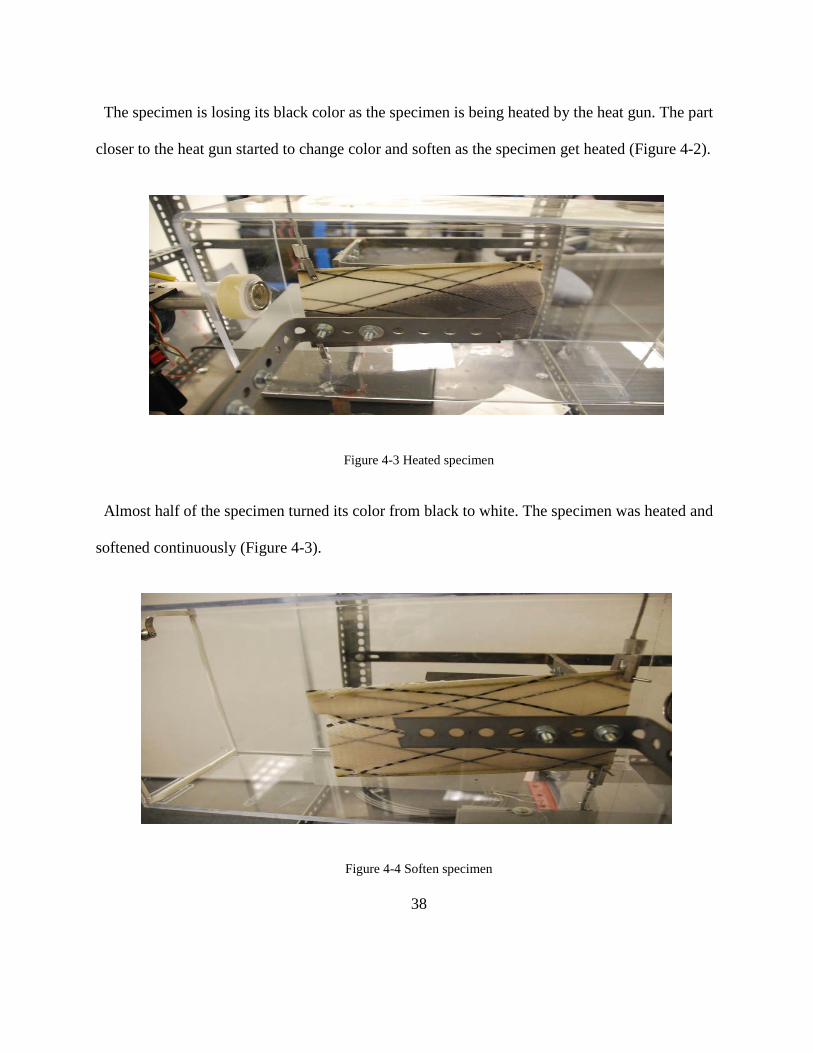
Figure 4-2 Changing color of specimen
38
The specimen is losing its black color as the specimen is being heated by the heat gun. The part
closer to the heat gun started to change color and soften as the specimen get heated (Figure 4-2).
Figure 4-3 Heated specimen
Almost half of the specimen turned its color from black to white. The specimen was heated and
softened continuously (Figure 4-3).
Figure 4-4 Soften specimen

39
While the SMP is being softened, the author loaded the tensile force in an axial direction. The
load made deformation in the specimen easy (Figures 4-4, 5).
Figure 4-5 Deformed specimen
Figure 4-6 Optical microscopic images of SMP composite specimen [14]
Microscopic figures (Figure 4-6) from Liu’s article shows an optical microscopic image of an
SMP specimen. By referring to these figures, the author could clearly understand how the SMP
deformation process happens while the SMP is being heated [14]. The image of original shape
(left) shows the longitudinal fibers and the SMP matrix is pretty good, namely there is no failure
or delaminating in the composite. The image of storage (center) shows large delaminating gap
between the transverse fiber and the longitudinal fiber. The image of recovery (right) shows the
recovered configuration of fiber micro buckling at the same location of the previous image. A

40
small recovered delaminate gap also can be observed between the transverse fiber and the
longitudinal fiber.
4.2 Micromechanics Analysis
4.2.1 Purpose of Micromechanics Analysis
Micromechanics of material is the analysis of composite or heterogeneous materials on the
level of the individual phases that constitute these materials [15]. It deals with mechanical
properties of the constituent materials of the composite. The author could understand basic
principles of SMP deformation and properties of it by applying micromechanics analysis. Figure
4-7 shows the constituent properties of fiber and matrix materials are used to calculate the ply
properties using rule of mixture. Ply properties are used to calculate the laminate properties. In
this section mechanics of composites is used to understand the response characteristics of SMP
composites
Figure 4-7 Analyzing composites

41
4.2.2 Procedures of Micromechanics Analysis
4.2.2.1 Determining effective lamina properties
In order to analyze the lamina properties we used micromechanics using the rule of mixture
E11=Ef*Vf + Em*Vm . The volume fraction of fiber Vf and the volume fraction of matrix Vm
satisfy the total volume relation Vf+Vm=1. Ef and Em are Young’s modulus for fiber and matrix
materials and are obtained using experiments. We can obtain the ply Young’s modulii E11 and
E22 for the ply as given below [16]:
E11=Ef*Vf+Em*Vm , 1/E22 = Vf/Ef+Vm/Em ,
In order to apply this method, the author decided to select one of SMP specimen made using
Veriflex resin. From the given basic data, the specimen material has Vf=0.66, Vm=0.33 (weight
of fiber = 60.29g, weight of matrix = 30.84g). Figure 4-8 is the specimen representing the SMP
composite laminate. The analysis is done by micromechanics and the laminate analysis modules
given in the Automated System for Composite Analysis (ASCA).
Figure 4-8 Specimen sample
42
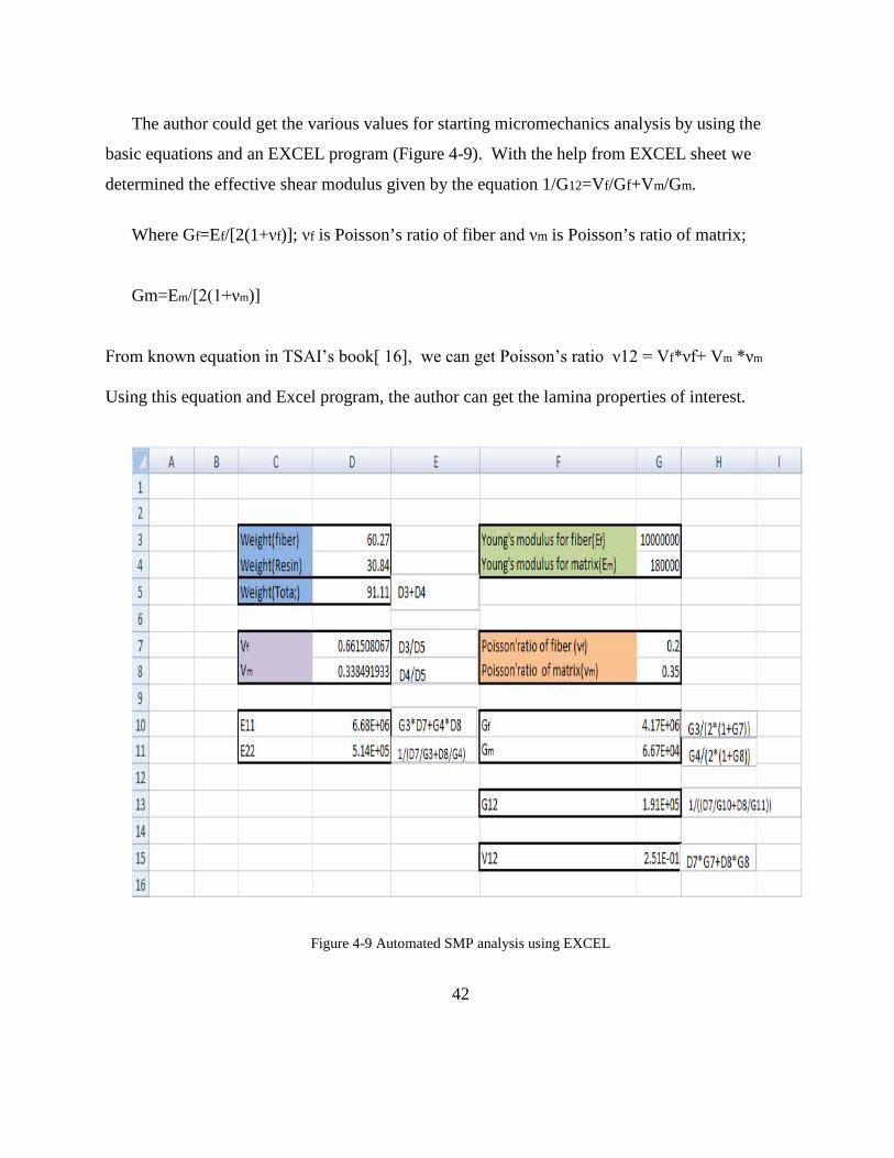
The author could get the various values for starting micromechanics analysis by using the
basic equations and an EXCEL program (Figure 4-9). With the help from EXCEL sheet we
determined the effective shear modulus given by the equation 1/G12=Vf/Gf+Vm/Gm.
Where Gf=Ef/[2(1+νf)]; νf is Poisson’s ratio of fiber and νm is Poisson’s ratio of matrix;
Gm=Em/[2(1+νm)]
From known equation in TSAI’s book[ 16], we can get Poisson’s ratio ν12 = Vf*νf+ Vm *νm
Using this equation and Excel program, the author can get the lamina properties of interest.
Figure 4-9 Automated SMP analysis using EXCEL
43
By substituting the values for Ef, Em, νm, we can determine the Gf and Gm values
Gf=Ef/2[(1+νf)]= 4.17Msi , Gm=Em/[2(1+νm)]=0.06Msi.
By substituting the values for Gf and Gm, we can determine G12 :
1/G12=Vf/Gf+Vm/Gm; G12=0.19 Msi
By using these values, we can analyze the specimen using an ASCA program.
4.2.2.2 Automated system for composite analysis (ASCA) program
ASCA has four modules. We have used two modules namely, Composite Laminate Analysis
Program (CLAP) and Free Edge Stress Analysis Program (FESAP). The details are given in
reference [ 17 ].
a. Composite Laminate Analysis Program (CLAP) analysis
CLAP is an interactive program which conducts point stress and failure analyses of general
laminates. CLAP can determine the overall modulus and compliance matrices of the laminate
along with its effective modules, poisson’s ratio and hydrothermal properties [17].
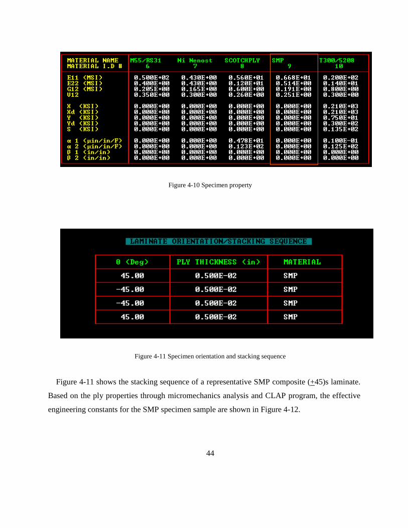
Figure 4-10 shows the lamina data used in ASCA for a representative SMP specimen
composite (+45)s laminate.
44
Figure 4-10 Specimen property
Figure 4-11 Specimen orientation and stacking sequence
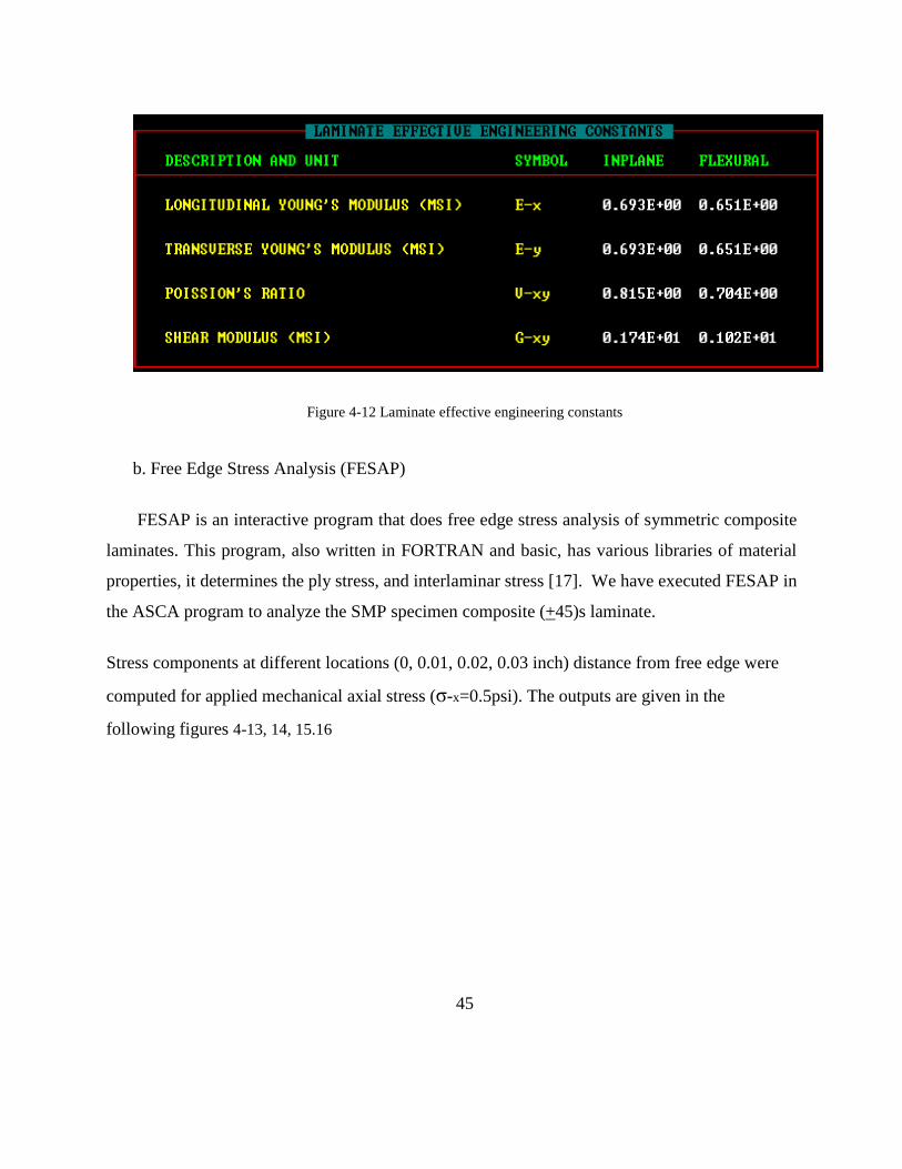
Figure 4-11 shows the stacking sequence of a representative SMP composite (+45)s laminate.
Based on the ply properties through micromechanics analysis and CLAP program, the effective
engineering constants for the SMP specimen sample are shown in Figure 4-12.
45
Figure 4-12 Laminate effective engineering constants
b. Free Edge Stress Analysis (FESAP)
FESAP is an interactive program that does free edge stress analysis of symmetric composite
laminates. This program, also written in FORTRAN and basic, has various libraries of material
properties, it determines the ply stress, and interlaminar stress [17]. We have executed FESAP in
the ASCA program to analyze the SMP specimen composite (+45)s laminate.
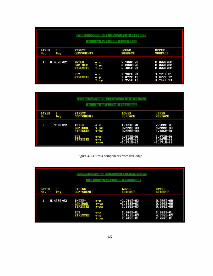
Stress components at different locations (0, 0.01, 0.02, 0.03 inch) distance from free edge were
computed for applied mechanical axial stress (σ-x=0.5psi). The outputs are given in the
following figures 4-13, 14, 15.16
46
Figure 4-13 Stress components from free edge

47
Figure 4-14 Stress components at 0.01 inch
Figure 4-15 Stress components at 0.02 inch
48
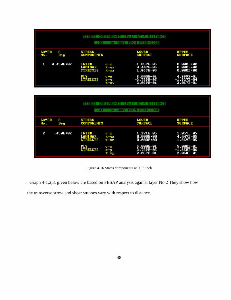
Figure 4-16 Stress components at 0.03 inch
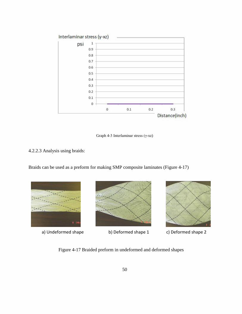
Graph 4-1,2,3, given below are based on FESAP analysis against layer No.2 They show how
the transverse stress and shear stresses vary with respect to distance.

49
Graph 4-1 Interlaminar stress (σ-z)
Graph 4-2 Interlaminar stress (γ-yz)
50
Graph 4-3 Interlaminar stress (γ-xz)
4.2.2.3 Analysis using braids:
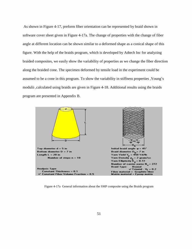
Braids can be used as a preform for making SMP composite laminates (Figure 4-17)
Figure 4-17 Braided preform in undeformed and deformed shapes
a) Undeformed shape b) Deformed shape 1 c) Deformed shape 2
51
As shown in Figure 4-17, preform fiber orientation can be represented by braid shown in
software cover sheet given in Figure 4-17a. The change of properties with the change of fiber
angle at different location can be shown similar to a deformed shape as a conical shape of this
figure. With the help of the braids program, which is developed by Adtech Inc for analyzing
braided composites, we easily show the variability of properties as we change the fiber direction
along the braided cone. The specimen deformed by tensile load in the experiment could be
assumed to be a cone in this program. To show the variability in stiffness properties ,Young’s
modulii ,calculated using braids are given in Figure 4-18. Additional results using the braids
program are presented in Appendix B.
Figure 4-17a General information about the SMP composite using the Braids program

52
Figure 4-18 Young modulus of specimen
4.3 Thermo-Mechanical Fatigue Testing
4.3.1 Purpose of Thermo-Mechanical Fatigue Testing
SMP are expanding its usefulness in a wide variety of applications, however the stress strain
response and failure mechanisms of SMP are still not well understood because it is a relatively
new structural material. The fact that SMP are being used in a variety of temperatures is another
challenge for understanding the properties of SMP. In order to get the properties of SMP in
various temperatures, new test methods are essential like a thermo-mechanical fatigue test. The
idealized thermo mechanical fatigue test, with loading patterns is usually used in a material
characterization test. The mechanical loading and thermal loading are applied to the test
specimens either in-phase or out of phase [18]. By experimenting with this TMF test, we can
identify how TMF would affect SMP. This test will also show how morphing wing based on
SMP should be maintained and fixed as temperature changes.

53
4.3.2. TMF Testing Procedure
a. Preparing SMP composite specimen made with resin and fiber.
b. A hole in the center of the specimen monitors how thermo-mechanical
fatigue will affect the hole in the specimen
c. The author applied thermal the fatigue load shown in Graph 4-4 , below.
Graph 4-4 Graph of thermo mechanical load
d. The author used C-SCAN against the specimen in order to identify differences between the
original and thermo-mechanical loaded specimen (Figure 4-19, 20)
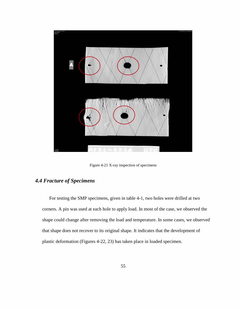
e. After C-SCAN, X-ray inspection was executed in order to monitor the difference among
specimens (Figure 4-21).
Throughout the C-SCAN we conducted nondestructive inspection for composites in which
short pulse of ultrasonic energy is incident on a sample. The thermo-mechanical loaded specimen

54
shows that it has more gray colored part. It means that this part has the possibility of such as the
delaminating, transformed fiber, and any foreign inclusions present. X-ray inspection (Figure 4-
21) shows that fracture happened in the side hole of thermo mechanical loaded specimen
compared to original specimen because repeated thermo mechanical load acted on the hole.
Figure 4-19 Original specimen
Figure 4-20 Thermo-mechanical loaded specimen
55
Figure 4-21 X-ray inspection of specimens
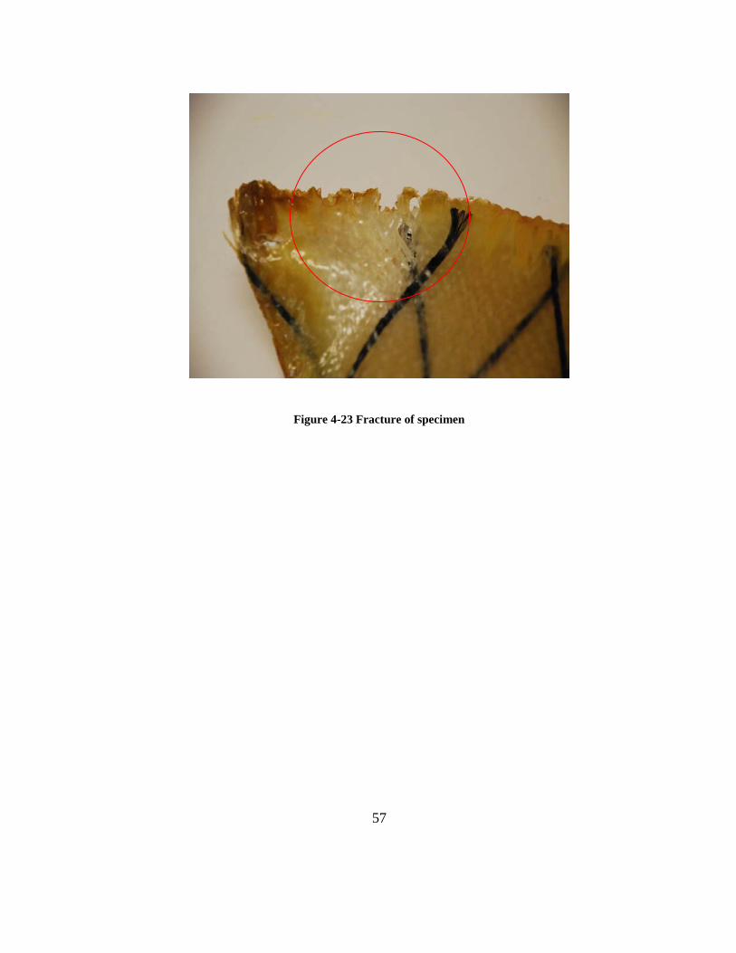
4.4 Fracture of Specimens
For testing the SMP specimens, given in table 4-1, two holes were drilled at two
corners. A pin was used at each hole to apply load. In most of the case, we observed the
shape could change after removing the load and temperature. In some cases, we observed
that shape does not recover to its original shape. It indicates that the development of
plastic deformation (Figures 4-22, 23) has taken place in loaded specimen.

56
Table 4-1 Table of specimen
Vf Specimens Tested specimens Cycles
0.59 2 1 5
0.65 2 1 10
0.66 2 1 15
0.67 2 1 50
Figure 4-22 Fracture of Specimen
57
Figure 4-23 Fracture of specimen

58
4.5 Ideas for development of morphing wing
This area of research is in initial stage of development. Lot more research work needs to be
done before SMP materials can be used in morphing wing aircraft. Some of the relevant areas
are:
1. Effective properties with different volume fractures of fiber, matrix, location
development and fiber angles
2. Heat transfer in SMP composites
3. Thermo mechanical fatigue and relevant mechanisms
The SMP analyzed does not seem to have adequate shape retaining capability for use in
morphing wing aircraft. This material may be useful for application requiring shape retaining
capability of up to 50 cycles such as munitions applications.
4.5.1 SMP composite having heat tube
According to the SMP material deformation test, the transforming rate of a morphing wing is
up to the heat source and the actuator. How soon the wing is heated and how soon the actuator
transmit load to the wing material determine the transforming rate of the morphing wing. To get
the quicker and more reliable heating and actuating method, many scientists are still studying
this issue. Researchers have explored the possibility of a SMP composite with a heat source tube.
The devised SMP composite (Figure 4-24) has its own heat tube inside of the composite. The
heat can be transferred from heat tube to the fiber and resin in the morphing wing material. If the
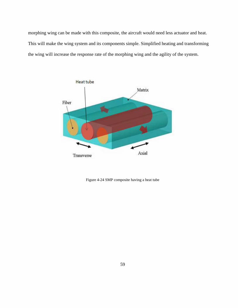
59
morphing wing can be made with this composite, the aircraft would need less actuator and heat.
This will make the wing system and its components simple. Simplified heating and transforming
the wing will increase the response rate of the morphing wing and the agility of the system.
Figure 4-24 SMP composite having a heat tube
60
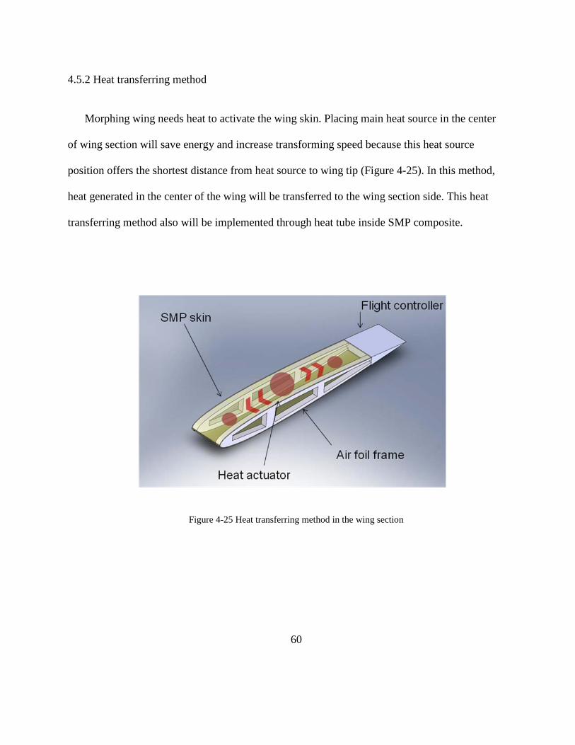
4.5.2 Heat transferring method
Morphing wing needs heat to activate the wing skin. Placing main heat source in the center
of wing section will save energy and increase transforming speed because this heat source
position offers the shortest distance from heat source to wing tip (Figure 4-25). In this method,
heat generated in the center of the wing will be transferred to the wing section side. This heat
transferring method also will be implemented through heat tube inside SMP composite.
Figure 4-25 Heat transferring method in the wing section

61
V. Conclusions and Recommendations
Finally the author can make several conclusions about the research conducted for this study.
Each conclusion can be a recommendation for near or long term for other researches. The author
wants the accomplishment and results of this research to further develop an integrated system
that provide directions for manufacturing, maintaining, and operating morphing wing aircraft,
and advancing the MWS concept to implementation.
5.1 Morphing Wing Aircraft – Potential Air Force’s Future Alternative
Current warfare is changing rapidly. The U.S Air Force needs new aircraft to provide longer
flight time, less fuel consumption, and better aerodynamics in order to perform Air Force
missions successfully. Currently morphing wings are developing all over the world; some of
them are deployed like on UAV (Unmanned Aerial Vehicle). Throughout this thesis, we tried to
make sure that morphing wing aircraft based on SMP wing skin is implementable, and to
estimate how they will be operated in the Air Force. Thus, US Air Force should be more
concerned about developing new alternatives for future wars.
5.2 Properties of SMP
This thesis provides mechanical characterization for SMP composites under consideration.
The mechanical properties found in the research can be used in various fields in case of SMP
application. This thesis has done several experiments using SMP in order to identify its unique

62
characterization. The author showed how SMP composite has formed its various shape when
axial load was applied and heated. This thesis also explored micromechanics analysis in order to
analyze the material on the level of the individual phases with the help of the ASCA program.
Finally this thesis showed how thermo mechanical fatigue would affect morphing material
throughout the thermo mechanical test. From the results and data of the experiment, the author
and advisor observed several issues with morphing material which are essential for successful
implementation
• Morphing material skin needs additional sub systems to activate morphing material.
It needs a heat source and actuating equipment. This equipment is essential for
activating morphing material.
• Morphing material skin takes some time to form its shape, because it take some time
to softening material and actuate for the desired shape.
• Morphing material skin should be monitored regularly because it could produce
thermo mechanical fatigue while it is heated and cooled.
• Managing morphing material skin means monitoring a lot of data and values at the
same time, because each morphing wing skin need to be transformed as each actuator
directs various controls and management are needed on each morphing wing skin
airfoil.
Throughout the property test, the author and advisor concluded that US Air Force should
develop different systems from conventional aircraft wings in order to deploy morphing wing

63
because morphing material has very unique properties compared to other fixed material. The
SMP composite system tested has limitations with regard to retaining its shape changing
capability beyond 50 cycles. Thus this material is not suitable for morphing wing aircraft.
64
5.3 Directions for Future Works
The author and advisor conducted research with emerging morphing material. There is still a
lot more to be studied in various properties of morphing material. Some of the areas of focus for
future work follow:
• Study the difference between SMP and SMP Alloy when applied to morphing wing
skin
• Perform experiments to study the repeatability of SMP memory effect, then, compare
them to other morphing material
• Improve the loading mechanism by inventing better ways to affect shape and
dimension change in specimens with greater repeatability and reliability
• Study the effect of different types and sizes of braids on the strength and shape of
composites
• Develop a heat transferring system in the wing skin with less heat loss

65
References
1. Albert, Alan P. and others, A Systems Engineering Approach to Integrated Structural Health Monitoring for Aging Aircraft. MS thesis, AFIT/GSE/ENY/06-M02. School of Engineering and Management, Air Force Institute of Technology (AU), Wright-Patterson AFB OH, March 2006.
2. Terrence A. Weissharr, Morphing aircraft technology-New shapes for aircraft design,
Purdue university, March 2006, pp. 5 3. Jason Bowman, Deveopment of Next Generation Morphing Aircraft Structure. Nextgen
Aeronautics, AIAA 2007-1730, pp. 2 4. Korey Edward Gross, Mechanical characterization of shape memory polymers to assess
candidacy as morphing aircraft skin, University of Pittsburgh , March 2008, pp. 9-10. 5. Derek R. Bye and Paul D. McClure, Design of a Morphing Vehicle, Lockheed Martin
Aeronautics Company, AIAA 2007-1728, pp. 2-4 6. Marc Behl and Andreas Lendlein, Shape Memory Polymers, Institute of Polymer Research,
Materialstoday April 2007. pp. 2. 7. Definition of System Engineering, Wikipedia, http://en.wikipedia.org/wiki/Systems_engineering. 8. Jean R.Gebman, Opportunities for system engineering to contribute to durability and damage
tolerance of hybrid structures for airframes, Rand reaserch, March 2007, pp. 2.
9. Buede, Dennis. Engineering Design of Systems: Models and Methods. John Wiley and Sons,
NY 1999.2nd Ed. 10. Definition and advantage of Vee model, Wikipedia, http://en.wikipedia.org/wiki/V-Model. 11. Veriflex E2 resin manual, CRG industries, http://www.crg-industries.com/veritex.html.
66
12. DoD Architecture Framework Working Group, DoDAF Version.2.0 Volume I, Electronic
copy, http://www.defenselink.mil.
13. M A Di Prima, “Thermo-mechanical Behavior of Epoxy shape memory polymer of foams”,
Smart Materials and Structures, June 2007, pp. 4. 14. Xin Lan, Yanju Liu, “Fiber reinforced shape memory polymer composite and its application
in a deployable hinge”, Smart Materials and Structures, January 2009. 15. Definition of Micromechanics, Wikipedia, http://en.wikipedia.org/wiki/Micromechanics. 16. Stephen W.TSAI, Composites Design, Think Composites, Third Ed.
17. Som R. Soni, Automated System for Composite Analysis, Technomic Publishing CO. pp. 41-44.
18. M. Xie, N. Frey, “Thermo mechanical fatigue testing of ceramic matrix composite plates with a hole”, Adtech System research, pp. 111.
19. Gerald R. Anderson and David L.Cowan, “Aeroelastic modeling, analysis and testing of a
morphing wing structure”, AIAA 2007-1734, pp. 3. 20. ACC/XPS U.S Air Force, Global Strike CONOPS, unclassified, June 2003. pp 4.

67
This page is intentionally blank

68
Appendix A

69
System engineering application for morphing aircraft
A.1 Morphing Wing Operating System (MWOS) SE Design Process
The MWOS design process is begun with the problem statement. The author tried to include
all the possible aspects of problem. The problem statement converged to a system engineering
application for practicality, cost-effective morphing wing system, and improving the safety of
flight parameters. The problem statement detail follows:
Practicality, realization
Practicality in MWOS means operating the morphing wing should be practical for various
missions and compatible with other US Air Force systems. MWOS is a developing system, so it
is hard to specifically identify entire behaviors of MWOS. Thus the author tried to make a blue
print of MWOS focused on the main function of the system.
Cost effective
Determining cost related issues was difficult for this thesis because a morphing wing system
is a developing system, so it is hard to estimate a budget to pay for components of wing and
maintenance cost in operation. The MWOS life- cycle cost includes cost from cradle to grave
following six steps (Table A-1).

70
Table A-1 Description of various costs
Phase Step Description
1 Cost of design The expense for designing MWOS and supporting facilities
2 Cost of acquisition The expense for purchasing morphing wings and facilities for operating it
3 Cost to install the
MWOS
The expense for operating the MWOS after purchase step. This cost
includes expense for software and manpower to operate morphing wings
4 Cost for operational
adoption
All the expense for making morphing wing aircraft perform all the missions
successfully required from that installed state.
5 Cost to maintain
MWOS
The expense for maintaining morphing wings regularly according to
maintenance plans
6 Cost of disposal The cost for disposing the morphing wing according to its life cycle
A.2 MWOS Life Cycle Phases
System engineering considers the life cycle of a system important because the system is not a
present condition but is a developing condition for the future. Life cycle means a series of stages
through which a system passes from its inception to its retirement. The start of any system
happens with the emergence of a need for new capabilities. Then, all the needs from various
stakeholders are considered to design the system. This step is the beginning of the development

71
period where the system engineers and the stakeholders work together. Following the completion
of the design phase is the integration phase, the production phase, the operational phase, and
finally the retirement, disposal or replacement phase [8]. These five phases involve five kinds of
activities. First is the conceptual phase, where the requirement, architecture and models are
developed. Second is the integration phase where various concepts and models are integrated.
Third phase is the production phase where designed system is produced. Fourth phase is the
operational phase where system is fully deployed. Fifth period includes all the disposal and
retirement of system. The life cycle phases of system are shown below (Figure A-1). All the life
cycle phases have their own value. Although the life cycle phases are shown as distinct and
separate items in figure A-1, each figure is a continuation of the previous one. This continuation
is very important. The author used this representation of life cycle to produce architecture for
MWOS.
Figure A-1 Life cycle of MWOS
72
A.3 MWOS Stakeholders
The process which creates a list of MWOS life cycle phase and identifies the stakeholders for
each phase is also an important step in system engineering. The author tried to understand and
describe the viewpoint and the requirements of each category of stakeholders. This process also
helped the author identify each phase which related to each stakeholder and from where system
requirements should be derived. According to Buede, the author should answer the critical
question “who has the right to have a requirement for the system?” in order to identify
stakeholders.
A.3.1 Conceptual/design phase
This phase sets up initial concepts and develops technology development strategies.
Stakeholders in various fields initiate the concept of desired system, and other stakeholders
provide the realm of the possible given available technology.
A.3.2 Integration/Development phase
For the second phase, development stage, the author identified two major stakeholders. They
are Office of the Security of Defense(OSD) , Air force. These stakeholders are mutually related
to each other and work together sometimes. The OSD and US Congress is the main bill payer.
They restrict the budget to purchase morphing wing aircraft and its system. Because they decide
on the initiation and continuance of the project, OSD should consider many aspects of MWOS
from other stakeholders.
73
The OSD might compare the advantage of MWOS to the conventional aircraft. They also
evaluate the operational adoptability of morphing wing aircraft to other services such as Army,
Navy in order to improve joint operational capability. They might express various opinion based
on their aspect. For example, the Army specialist might evaluate the adoptability of Morphing
wing aircraft in case it is deployed to the Close Air Support mission. They might analyze the
good and bad of morphing wing aircraft in terms of their operational achievement. OSD is
controlling the finance. They have to analyze all the cost of MWOS in each phase of system.
Then, they should make a plan for controlling the budget throughout the life cycle. Another
concern of the OSD stakeholder is acquisition work. The OSD oversees the entire system
acquisition plan. They check the entire system acquisition duration and test plan, entire budget
etc. They manage all the process during system acquisition.
Another stakeholder in the development phase is the Air Force. Actually the Air Force is the
main actor who use and maintain this system. Requirement for implementing this system should
be collected from many Air Force staffs who would participate in this system. Air force
stakeholder can be divided in to three major parts. First part controls the operational capability.
They should analyze operational effectiveness of Morphing wing aircraft when it comes to apply
for various air force missions. The second part controls maintenance. They should present the
entire requirement in managing maintenance system for morphing wing aircraft. Morphing wing
aircraft have different wings consisting of different material compared to conventional aircraft.
This unique fact needs more different subsystems in maintenance aircrafts. These differences of
the system should be fully considered by the Air Force stakeholder. The Air Force stakeholder

74
controls acquisition. Acquisition officers in the air force deals with the entire acquisition budget
and plan. They should consider cost and duration when they acquire the system.
A.3.3 Production/Training phase
This phase deals with producing the system and training users. The system is produced as
designed in previous phase. At the same time the training phase happens. Training phase has two
kinds of stakeholders. The first is trainer and another is trainees. The trainers also consists of two
parts; contractor’s training department and Air force Training Agencies. Contractor Company
produces morphing wing aircraft with the manual for maintenance and flight control. The
developers and contractor’s training department who produced morphing wing aircraft in the
contract company should train the pilot and maintenance agencies who are supposed to take over
morphing wing aircraft for the training phase.
A.3.4 Operational phase stakeholders
Deployment is the stage which has the longest time among five phases. Air force is the main
stakeholder in this phase. Air force deploys MWOS to attain the operational concept. Air Force
stakeholder can be divided into three specific stakeholders. The first stakeholder is operational
operators. They actually control and use the morphing wing aircraft in various Air Force
missions. The second stakeholder is maintenance operators. They perform maintenance against
75
morphing wing regularly according to the maintenance plan. They also fix abrupt functional
failure and report mechanical failures to headquarters and contractor’s company. The third
stakeholder is logistics teams. They first take over logistics of MWOS from contractor’s
company. They provide logistics in order to maintain current equipments as planned by system
designers. Some of them should plan for the replacement of system. Morphing wing is not
permanent wing. It loses its capability as time goes by or by the accident. The logistic
stakeholder should provide appropriate substitution for the parts need to be replaced.
A.3.5 Retirement phase stakeholders
In the final phase of the system’s life cycle, the main stakeholder is DoD and Air force. Both
these stakeholders will need to develop a plan for the retirement of the MWOS system. If the
system has still remaining useful advantage, MWOS will be adopted to other system. If the
system is useless and need to be discarded, the MWOS will be disposed as planned [1].
76
A.4 Operational Concepts
Initially operational concepts are abstract; however, concepts can be evolved over time.
Some CONOPS describe how a mission is to be carried out. The author tried to identify how
CONOPS describes the ways (sequenced actions) we use to employ mean (military capabilities)
to accomplish desired end (effects) in MWOS.
A.4.1 Problem
As science develops, potential adversaries become increasingly camouflaged and agile.
Traditionally, US military operations have relied on the ability to deploy superior power close to
an adversary using time constrained capabilities in the air. To take advantage of such a
deployment of forces, potential adversary’s targets are getting smaller and harder to detect.
Adversaries emphasize camouflage and anti-access action, the required friendly flight time in the
target area is increasing. The fundamental resolution of this problem requires a lot of transitions
to current systems. One of these transitions is developing morphing wing aircraft and operating
them in this mission environment [20].
A.4.2. Objectives
The objective of MWOS is to gain improved mission capability using morphing wing aircraft,
which provides advanced aerodynamic performance.
77
A.4.3 Desired effects
To achieve the desired goal for the US forces, MWOS CONOPS requires the ability to achieve
three overarching effects. First the defined capabilities used to execute the MWOS CONOPS
will be adapted to the battle space. Second, MWOS will work for improving mission success
rate by improved aerodynamic wings. Third, MWOS will establish required sub systems to
maintain its own functions.
A.4.4 Capabilities
The capabilities within the CONOPS will be described by creating sets of scenarios for the life
cycle phase of the system. The system engineers identify the stakeholders in the
conceptual/design phase, system engineer find out the needs from customers and integrate and
present them with system engineering tools. Agreement is achieved among the stakeholders on
the proposed concept. The next sub phase is integration/development phase. The purpose of this
phase is creating a System Engineering Plan (SEP) and define “who, what, when, where, why,
and how the applied SE approach” They organize system engineering, design and define detailed
roles for their members. System engineers develop CONOPS from the user’s requirements and
develop the MWOS system architectures. The system design team develops the configuration
item (CI) list and the design for each item. The integration plan and verification-validation
requirements are defined. The CI includes the requirements set by the manufactures. The system
engineer and developer create a prototype of the system. This prototype will go through
validation testing. During the testing the designer validate if CIs and requirements from customer

78
are reflected satisfactorily. The design team reviews unsatisfactory CIs. If the validation is
successful, the prototype design of MWOS is approved for production. In the production phase,
the manufactures get into a contract with the DoD, AF acquisition stakeholders. They produce
required equipments for MWOS system. When production of system is completed, the
operational/deployment phase starts in earnest. Deployment plan is arranged between AF
stakeholders. The locations of the system installation, equipments required, and schedules are
defined. As the first MWOS is installed, the problems are revealed. The designer find a solution
to the problem with stakeholders, then make feedback in order to prevent the problems in the
following system production. In the operational phase, the MWOS will be operated in the battle
place. MWOS will perform various air force missions such as air to air mission like an
Interdiction and air to ground such as close air support. As many MWOS are operated, more
experience from the system’s operation is accumulated; the need for some
improvements/modification may arise. The data collected from the MWOS are analyzed and
feedback is sent to the manufacturers and the designers. By this repeated process, MWOS will be
operating. As the MWOS is approaching to the end of its design life, system designer and
operator should evaluate the situation and make a plan for the retirement of the system. They
have to cooperate with the stakeholder in the headquarters to make final decision. If they decide
to agree retirement plan, system engineer and engineers have to retire MWOS with less
pollution.
79
A.5 MWOS Operational Objectives Hierarchy
The system should be intuitive and easy to operate. To make the system feasible as desired,
the development of the weighted objectives hierarchy and performance is helpful. This hierarchy
defined cost, and performance goals stakeholders required for an acceptable system design.
Using this objectives hierarchy provides great help to originate system requirement. The MWOS
operational objectives hierarchy consists of two major parts (Figure A-2). The first part is system
operating cost. It includes cost of acquisition, development, installation, operation, and disposal
of the MWOS. The author classified the system operating cost with weight. The author set the
weight portion based on the estimation. The other part is about the performance. This part
includes deformation success rate, speed of deformation, available degree of sweep angle, fix
rate, increased flight time. These factors are the essential part to measure performance of
morphing wing. The author set the required criteria considering conventional aircraft
performance, property of SMP. This work also was classified by the weight portion.

80
Figure A-2 Operational objective hierarchy

81
A.6 DoDAF Architectures for MWOS
In chapter 3, the author discussed what system architectures, their importance, are and the
methodology used to develop the architecture product. In this section, architecture framework
using DoDAF 2.0 is presented along with a brief description on the development process for
each view.
A.6.1 All views
The first important architecture product is AV-1 and AV-2, which is a textual definition and
description of the problem, and purpose and scope of the architecture products follow. AV-1
basically describes the boundaries of the architecture. AV-2 will be omitted in this thesis.
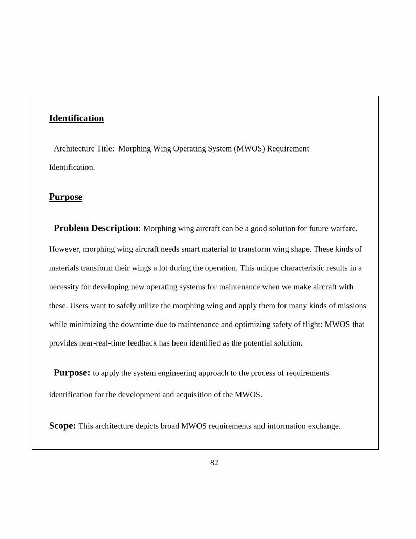
82
Identification
Architecture Title: Morphing Wing Operating System (MWOS) Requirement
Identification.
Purpose
Problem Description: Morphing wing aircraft can be a good solution for future warfare.
However, morphing wing aircraft needs smart material to transform wing shape. These kinds of
materials transform their wings a lot during the operation. This unique characteristic results in a
necessity for developing new operating systems for maintenance when we make aircraft with
these. Users want to safely utilize the morphing wing and apply them for many kinds of missions
while minimizing the downtime due to maintenance and optimizing safety of flight: MWOS that
provides near-real-time feedback has been identified as the potential solution.
Purpose: to apply the system engineering approach to the process of requirements
identification for the development and acquisition of the MWOS.
Scope: This architecture depicts broad MWOS requirements and information exchange.

83
A.6.2 Operational Architectures
A.6.2.1 OV-1
The first architecture product the author produced is the OV-1. OV-1 is the high level
description of the operational concept. MWOS at the center symbolizes developed (Figure A-3).
The circle around the MWOS represents system boundaries that will be affected by the
development and implementation of MWOS.
Figure A-3 MWOS OV-1
84
A.6.2.2 OV-5: Operational Activity Diagram
The next architecture view is the OV-5. The OV-5 has two kinds of diagrams, operational
activity and node tree. By defining the main purpose of the architecture, helping identify the
MWOS requirements, the author started the OV-5 development. The author monitored current
wing operating systems and decomposed requirements from them. The author realized that four
major requirements should be determined for MWOS. The first one determines operational
requirement. This requirement relates to operational activities. This requirement can be
decomposed into three sub requirements. They are analyzing mission requirement, providing
necessary aircraft maintenance, and making MWOS decisions. These sub requirements control
the operational requirement. The second requirement is determining the wing deformation
requirement. This requirement is the unique function that does not exist in other wing operating
systems. This requirement exists in order to transform the wing according to users’ requests.
Three major sub requirements should be determined to keep the wing deformed. They are
actuator location, actuator capability, and heat source. Actuator location is important in that it
determine the shape of wing. A morphing wing can change to a lot of formations. Each
formation should have a different actuation location in order to make the desired shape. Actuator
capability is also an important factor. Every actuator should have reliability and accurate control.
The last function for determining wing deformation requirement considers heat source. SMP
cannot get transformed without a heat source. Thus, keeping the heat source in proper place and
time is an essential factor for determining wing deformation requirements. The third major
requirement for MWOS is determining data requirements. A lot of kinds of data will be used in

85
MWOS like other conventional systems. These data should be organized, processed, and used for
keeping MWOS operated properly. All the functions are organized throughout OV-5 node tree
(Figure A-4)
Figure A-4 OV-5 Node tree
In order to determine these data requirements, three sub requirements should be considered.
They relate to analysis, storage, and processing of data. While the wing is deformed and used, a
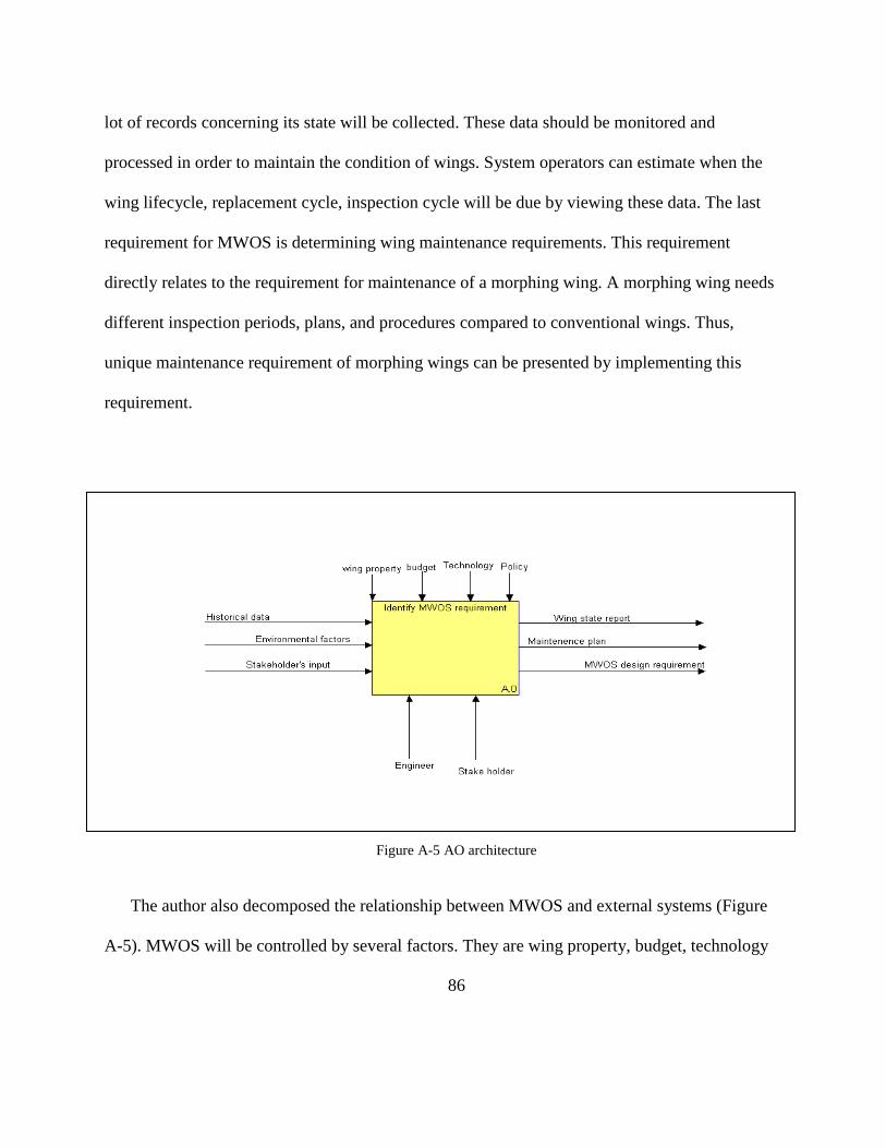
86
lot of records concerning its state will be collected. These data should be monitored and
processed in order to maintain the condition of wings. System operators can estimate when the
wing lifecycle, replacement cycle, inspection cycle will be due by viewing these data. The last
requirement for MWOS is determining wing maintenance requirements. This requirement
directly relates to the requirement for maintenance of a morphing wing. A morphing wing needs
different inspection periods, plans, and procedures compared to conventional wings. Thus,
unique maintenance requirement of morphing wings can be presented by implementing this
requirement.
Figure A-5 AO architecture
The author also decomposed the relationship between MWOS and external systems (Figure
A-5). MWOS will be controlled by several factors. They are wing property, budget, technology
87
and policies. Wing property is general physical characteristics of SMP and its composites. The
wing made of SMP will also be affected by SMP characteristics. We also found that these
characteristics vary as physical condition changes throughout the experiments. Budget is the
second important sub requirement. MWOS might need a lot of subsystem and equipment.
However, budget is not an infinite resource. System engineers and operators should maintain the
balance in managing and controlling budget in implementing MWOS. The third sub requirement
factor is technology. Technology deals with how to transform, maintain, and fix morphing
wings. Advanced technology can transform wings in shorter time, providing better
maintainability. These technologies are still developing now. Innovative technology should be
applied to operating morphing wings by the system engineer’s interest. The last sub requirement
is policy. This is a very basic sub requirement. Every system should be established by the
guidance of AF and DoD policies. There is a possibility that some policies may conflict with
required system requirements. These conflicts should be resolved.
The author identified three major inputs in MWOS. They are historical data, environmental
factors, and stakeholder’s input. Historical data means all the previous records of morphing
wings. Environmental factors include external factors which could affect operation of morphing
wing systems. For example, there will be weather, mission area terrain, and temperature of air,
and so on. Stakeholder input means variety of common interest among stakeholders, who are
related to MWOS. Mission requests, and inspection plans could be examples of stakeholder’s
input (Figure A-6).

88
The author identified three major outputs of this enterprise. They are wing state report,
maintenance plan, and MWOS design requirements. They will be produced from MWOS
through engineer and stakeholder’s help. Some help will be feedback for MWOS. This makes the
system more reliable and stable.
Figure A-6 OV-5 A0 architecture
89
The author decomposed the context diagram into four major functions or activities that a
promotional MWOS should be expected to perform. Those are related to operation, maintenance,
data processing, overall management. The first requirement is determining operational
requirement. Operational requirement means all the requirements for performing missions in the
battlefield and managing issues for operating this system. As technology develop and strategy
changes, requirements in the mission should be changed. These changes will be transferred as a
policy or inputs of stakeholders, environmental factors, and historical data from feedback of
MWOS. After determining operational requirements optimized for morphing wing aircraft,
desired mission scenario will be produced. This product includes the mission type, jobs, and
even environmental factors which are considered in operating morphing wing aircraft. These
scenarios will be the input to the next function. The next function is determining wing
deformation requirement. This function deals with physical activity of MWOS, such as heating
and forming material. SMP deforming units will perform its role to keep the wing optimized
according to mission scenario. After determining this function, desired wing shape will be
produced. As morphing aircrafts are deployed more and more in the combat area, desired wing
shape data needs to be optimized and recorded in the MWOS. The third function deals with this
necessity. All the data which are processed and organized by previous functions will be the
output and feedback to the other functions. The last major function is determining wing
maintenance requirements. This function directly related to the maintenance. Morphing wing
needs periodical inspection, maintenance and preventive maintenance. Morphing wing needs
more strict maintenance and inspection compared to conventional aircraft, because malfunction

90
of deforming wing might be result in terrific disaster. After determining these functions, overall
maintenance plan could be produced.

91
Appendix B Table B-1 DoDAF 2.0 Products
Applicable view Model Product name Description
All views AV-1 Overview and Summary information
Describes a project’s vision, goal, objectives, plans, activities, events, condition, measures, effects.
All views AV-2 Integrated Dictionary An architectural data repository with definitions of all terms used throughout the architectural data and presentations
Capability CV-1 Vision The overall vision for transformational endeavors, which provides a strategic context for the capabilities described and a high level scope
Capability CV-2 Capability Taxonomy A hierarchy of capabilities which specifies all the capabilities that are referenced throughout one or more architectural descriptions
Capability CV-3 Capability Phasing The planned achievement of capability at different points in time or during specific periods of time
Capability CV-4 Capability Dependencies The dependencies between planned capabilities and the definition of logical groupings of capabilities
Capability CV-5 Capability to Organizational development mapping
The fulfillment of capability requirements shows the planned capability deployment and interconnection for a particular capability phase
Capability CV-6 Capability to Operational activities Mapping
A mapping between the capabilities required and the operational activities that those capabilities support
Capability CV-7 Capability to Services Mapping
A mapping between the capabilities and the services that these capabilities enable
Operational OV-1 High Level Operational Concept Graphic
The high-level graphical description of the operational concept
Operational OV-2 Operational Resource Flow description
A description of the resource flows exchanged between operational activities
Operational OV-3 Operational Resource Flow matrix
A description of the resource exchanged and the relevant attribute of the exchanges
Operational OV-4 Organizational Relationships chart
The organizational context, role or other relationships
Operational OV-5a Operational Activity Decomposition Tree
The capabilities and activities organized in an hierarchal structure
Operational OV-5b Operational Activity Model The context of capabilities and activities and their relationships among activities, inputs, and outputs

92
Applicable view Model Product name Description
Operational OV-6a Operational Rules Model One of three models used to describe activity. It identifies business rules that constrain operations
Operational OV-6b State Transition Description One of three models used to describe activity. It identifies business process responses to events
Operational OV-6c Event Trace Description One of three models used to describe operational activity. It traces actions in a scenario or sequence of events
Data/Info DIV-1 Conceptual Data Model The required high level data concepts and their relationships
Data/Info DIV-2 Logical Data Model The documentation of the data requirements and structural business process rules
Data/Info DIV-3 Physical Data Model The physical implementation format of the logical data model entities
Project PV-1 Project Portfolio Relationships Describes the dependency relationships between the organizations and projects and the organizational structures
Project PV-2 Project Timelines A timelines perspective on program or projects, with the key milestones and interdependencies
Project PV-3 Project to Capability Mapping A mapping of programs and projects to capabilities to show how the specific projects and program elements help to achieve a capability
System SV-1 System Interface Description The identification of system, system items, and their interconnections
System SV-2 System Resource Flow Description
A description of resource flows exchanged between systems
System SV-3 System-System Matrix The relationships among systems in a given architectural description
System SV-4 System Functionality Description
The functions performed by systems and the system data flows
System SV-5a Operational Activity to Systems Function Traceability Matrix
A mapping of system functions back to operational activities
System SV-5b Operational Activity to System Traceability Matrix
A mapping of system back to capabilities or operational activities
System SV-6 System Resource Flow Matrix Provides details of system resource flow elements being exchanged between systems and the attributes of that exchange

93
Applicable view Model Product name Description
System SV-7 System Measures Matrix The measures of system model elements for the appropriate time frame
System SV-8 System Evolution Description The planned incremental steps toward migrating a suite of systems to a more efficient suite or toward evolving a current system
System SV-9 System technology Skills forecast
The emerging technologies, skills that are expected to be available in a given set of time frame
System SV-10a System Rules Model One of three models used to describe system functionality
System SV-10b System State Transition Description
One of three models used to describe system functionality. It identifies responses of system to events
System SV-10c System Event-Trace Description One of three models used to describe system functionality. It identifies system specific refinements of critical sequences of events
Service SvcV-1 Services Context Description The identification of services, service items, and their interconnections
Service SvcV-2 Service Resource Flow Description
A description of resource flows exchanged between services
Service SvcV-3a System-Service Matrix The relationships among or between systems
Service SvcV-3b Services-Services Matrix The relationships among services in a given architectural description
Service SvcV-4 Services Functionality Description
The functions performed by services and the service data flows among service functions
Service SvcV-5 Operational Activity to Services Traceability Matrix
A mapping of services back to operational activities
Service SvcV-6 Services Resource Flow Matrix It provides details of service resource flow elements being exchanged between services and the attributes of that exchange
Service SvcV-7 Services Measures Matrix The measures of services model elements for the appropriate time frame
Service SvcV-8 Services Evolution Description
The planned incremental steps toward migrating a suite of services to a more efficient suite or toward evolving current services to a future implementation.
Service SvcV-9 Services Rules Model
One of three models used to describe service functionality
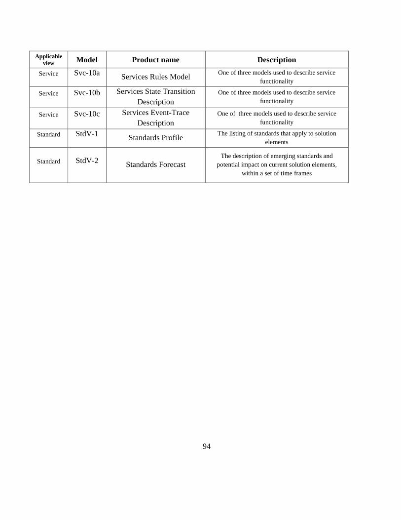
94
Applicable view Model Product name Description
Service Svc-10a Services Rules Model One of three models used to describe service functionality
Service Svc-10b Services State Transition Description
One of three models used to describe service functionality
Service Svc-10c Services Event-Trace Description
One of three models used to describe service functionality
Standard StdV-1 Standards Profile The listing of standards that apply to solution elements
Standard StdV-2 Standards Forecast The description of emerging standards and
potential impact on current solution elements, within a set of time frames
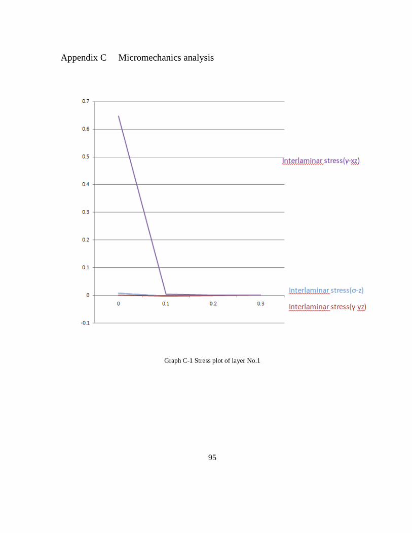
95
Appendix C Micromechanics analysis
Graph C-1 Stress plot of layer No.1
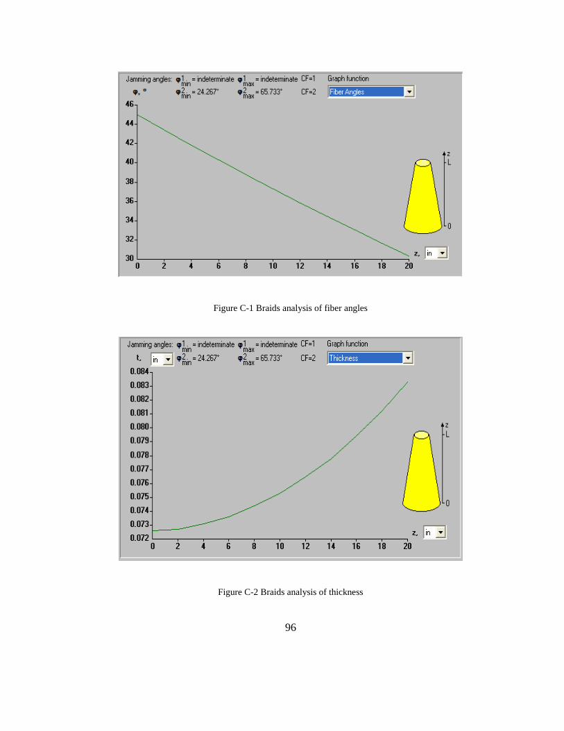
96
Figure C-1 Braids analysis of fiber angles
Figure C-2 Braids analysis of thickness
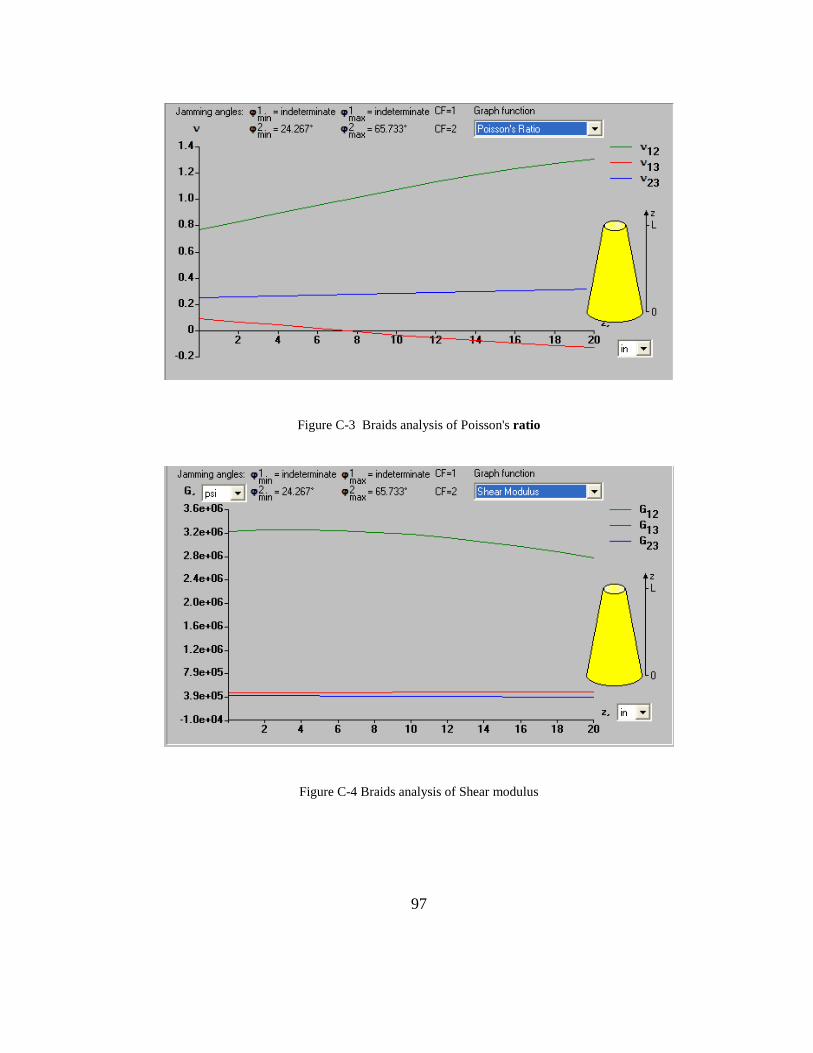
97
Figure C-3 Braids analysis of Poisson's ratio
Figure C-4 Braids analysis of Shear modulus

98
Figure C-5 Braids analysis of Young's modulus

99
Appendix D OV-2, SV-5b
Figure D-1 MWOS OV-2
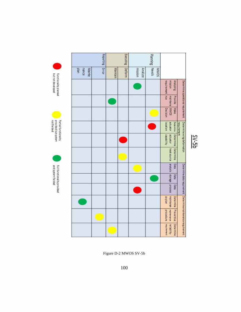
100
Figure D-2 MWOS SV-5b
101
REPORT DOCUMENTATION PAGE Form Approved
OMB No. 074-0188REPOOMB N o. 074-0188
The public reporting burden for this collection of information is estimated to average 1 hour per response, including the time for reviewing instructions, searching existing data sources, gathering and maintaining the data needed, and completing and reviewing the collection of information. Send comments regarding this burden estimate or any other aspect of the collection of information, including suggestions for reducing this burden to Department of Defense, Washington Headquarters Services, Directorate for Information Operations and Reports (0704-0188), 1215 Jefferson Davis Highway, Suite 1204, Arlington, VA 22202-4302. Respondents should be aware that notwithstanding any other provision of law, no person shall be subject to an penalty for failing to comply with a collection of information if it does not display a currently valid OMB control number. PLEASE DO NOT RETURN YOUR FORM TO THE ABOVE ADDRESS. 1. REPORT DATE (DD-MM-YYYY) March 2010
2. REPORT TYPE Master's Thesis
3. DATES COVERED (From – To) June 2009 - March 2010
4. TITLE AND SUBTITLE
DEVELOPMENT OF MORPHING AIRCRAFT USING SMP
5a. CONTRACT NUMBER
5b. GRANT NUMBER 5c. PROGRAM ELEMENT NUMBER
6. AUTHOR(S)
Soo-chan Jee, Capt, R.O.KAF
5d. PROJECT NUMBER 5e. TASK NUMBER 5f. WORK UNIT NUMBER
7. PERFORMING ORGANIZATION NAMES(S) AND ADDRESS(S)
Air Force Institute of Technology Graduate School of Engineering and Management (AFIT/EN) 2950 Hobson Way WPAFB OH 45433-7765
8. PERFORMING ORGANIZATION REPORT NUMBER
AFIT/GSE/ENV/10-M02
9. SPONSORING/MONITORING AGENCY NAME(S) AND ADDRESS(ES) Intentionally left blank
10. SPONSOR/MONITOR’S ACRONYM(S)
11. SPONSOR/MONITOR’S REPORT NUMBER(S) 12. DISTRIBUTION/AVAILABILITY STATEMENT
APPROVED FOR PUBLIC RELEASE; DISTRIBUTION UNLIMITED 13. SUPPLEMENTARY NOTES 14. ABSTRACT
The U.S Air Force needs new aircraft which provide longer flight time, less fuel consumption, better aerodynamics in order to perform Air Force missions successfully as the mission environment changes rapidly. A morphing wing aircraft is considered as a potential new aircraft for those missions. This thesis explores Shape Memory Polymer (SMP) properties test results and its applicacation for morphing wing skin. Several SMP composite laminates were considered for investigating shape changing characteristics required for morphing skin. The braided composite prefoms used in making SMP composites were explored in morphing wing operating system based on the results of property tests. The system definition, life cycle of system, user analysis, and some architecture for identifying systems effectively formed the basis for the generic system engineering process presented. Further, this thesis explores initial geometric deformability, recovery characteristics, material property estimates, and develops the system using morphing material in order to present a concept for emerging morphing wing aircraft as a potential future Air Force’s alternative. Based upon this research, the material system considered here does not meet the morphing requirement for such aircraft. 15. SUBJECT TERMS Morphing aircraft, SMP, structure, property, Thermo-mechanical fatigue, Fracture
16. SECURITY CLASSIFICATION OF: 17. LIMITATION OF ABSTRACT
UU
18. NUMBER OF PAGES 116
19a. NAME OF RESPONSIBLE PERSON Dr. Som Soni, AFIT/ENV
a. REPORT
U b. ABSTRACT
U c. THIS PAGE
U 19b. TELEPHONE NUMBER (Include area code)
(937) 785-3636 x 3420 [email protected]
Standard Form 298 (Rev. 8-98)
Prescribed by ANSI Std. Z39-18

102