development of mechanical design of the amphibious robot
TRANSCRIPT
Journal of Mechanical Engineering Research and Developments ISSN: 1024-1752 CODEN: JERDFO Vol. 43, No. 2, pp. 61-73 Published Year 2020
61
Development of Mechanical Design of The Amphibious Robot Muhannad Zaidan Khalefa* Iman S. Kareem & Rand Jaffer Jadoau
Department of Electromechanical Engineering, University of Technology, Baghdad, Iraq *E-mail: [email protected]
ABSTRACT: The aim of this research is to develop the mechanical design and compositions of the amphibious robot, which operate very efficiently, while walking on flat and rugged terrain as well as swimming under water, with the performance of its duty of detecting the operating zone by using a camera and multiple sensors. The total mass of the amphibious robot is about 24.5 kg. The design of the robot consists of the body which was made from Perspex type transparent and designed in two parts (front and rear parts). The movement of the robot while climbing obstacles is similar to the movement of the cockroach. The robot moves by three pairs of wheel legs, two pairs are named wheel legs-propeller (developed in this paper), each pair work by D.C motor and third pair type wheel legs (move without motor). When swimming in the water, two upper propellers were added at the outer surface of the top of each part of the body and the steering mechanism. The front and rear parts contain, mechanical and electrical components as well as four solar cells with charge controller in front part. The degree of freedom (DOF) of the amphibian robot body in this work was calculated (3 DOF). Using of LabVIEW program from National Instruments (NI) as the software in this work with data acquisition hardware to interface with the pc inside the robot as the main controller for the motors and sensors, program had been created to control the robot manually by user and automatically by inserting a path. Test had been made for the performance of the robot in flat ground, uneven ground and test for climbing the robot over an obstacle and go down in a hole as well as swimming of the robot in water with recording and storing the results.
KEYWORDS: Amphibious Robot; Wheel-Legs Propeller; Perspex Material; Upper Propellers; Steering Mechanism and LabVIEW Program
INTRODUCTION
Amphibious robots are usually based on wheels, legs or a combination of wheel-leg mechanical machines for movement on the ground. There is a kind of robot similar to the snake in movement on the ground. All types of robots have a complex mechanism of movement and control of movement except robots moving by wheel which are easier to control [1]. Described the designing generations of autonomous quite movable amphibian robot. A first generation basically ground model has been built and field examined. A waterproof second generation amphibious model designing, based on the biological inspiration WhegsTM platform, has been accomplished. The designing suits the unmatched movement of the wheel-legs with the autonomous devices and control architectures built in the first generation model [2]. Described the portability of autonomous platforms to work on beaches is serious to a wide range of military and civilian applications. especially important is the capability to autonomous navigate during rocky land, hard-packed wet sand, and loose dry sand which is usually found in these environments. In this paper, shown the design, manufacture, control system expansion and field-tested for the autonomous robotics that had biological inspiration to deployment and operated in a surf-zone environment [3]. Studied the design of a new kind of underwater vehicle, Remotely Operated Vehicles (ROV) that could hover and using for shallow water investigation [4]. Study the development of an amphibious legged quadrupedal robot and linked gaits. Important gaits included walking, swimming, and smoothly transmitted between the two. Compliance was used in the robot’s legs to obtain swimming [5]. Used rotational leg-type miniature robot with an actuated middle joint and tail, called RoMiRAMT, is proposed for stable locomotion and improved climbing ability. The robot has four independently actuated rotational legs, giving it advantages of both wheel-type and leg-type locomotion. A microcontroller was embedded in the robot, along with a micro-camera and an inertia measurement unit (IMU) sensor [6]. Presented a hybrid wheel-legged robot. First, the mechanical design of this structure was presented. Secondly, based on the kinematic analysis, a comparison was made between the robot in the case of an active transmission system and passive transmission system. Third, simulation was made to the procedure of overcoming three types of obstacle. Finally, the conclusion was made that this hybrid locomotion mechanism with the active transmission system has good performance on rough terrains [7]. Showed the mobility between

Development of Mechanical Design of The Amphibious Robot
62
aquatic and terrestrial environment and vice versa is a difficult problem for a robot, because it is necessary to change the gaits completely and make it suitable to the new environment, with non-stop [8]. Concluded the Leg-wheel method has gained method over the last decade in the number of robotic laboratories around the world. When applied to different platforms, it has independent mechanism and actuator for legs and wheels. This robot will perform with unique transformation mechanism which switches directly as driving mechanism on the wheels (full circle) and two degrees of freedom as leg (joining two divided circle as a leg). Then the actuating power is used in legged and wheeled modes [9].
The aim of this paper is to develop the design of amphibious robots that should be able to transverse on land and in water successfully. Design of amphibious robot consists of three degrees of freedom is composed of two parts unequal dimensions, contains two pair type of wheel legs-propeller (Whegs-P) and One pair type of wheel legs (Whegs), Adding two upper propeller at the top of each part for the purpose of lifting and landing the robot in water. The amphibious robot should contains vision systems by camera as well as navigation components. Finally using of four solar cells with solar charge controller for charging the 12V battery. In the present work LabVIEW is used for controlling the amphibious robot, a where program was written that provides a way to control the robot directly.
DEVELOPMENT OF MECHANICAL DESIGN OF AMPHIBIOUS ROBOT
Body Construction
Selected material was to manufacture durability of the body, not leaking and transparent to enter the sunlight of the solar cell surface for the purpose of charging the battery as well as all parts can be viewed from the outside. Article manufacturer of the body is from using poly propylene (methy methacrylate) which is also named Perspex or acrylic sheet. Outstanding properties of Perspex in [10].
The dimensions structure of the amphibious robot designer in this work consists of two parts: (i)- The dimensions of front part are: 40 x 25x15 cm3
(ii)- The dimensions of rear part are: 45 x 25 x 15 cm3
Types of The Wheels
Wheel-Legs Propeller (Whegs-P)
The frontal and rear wheel legs of the robot can be controlled by motor and able to climb up the obstacle , the obstacles height 30 cm, and also able to move on the land which is helping to push inside the water. This type consists of three parts as follows and as shown in Figure 1a, [11]:
(i)-Ring body that installs in the axis of rotation of the hand and the leg been shown its from the other side, this part of the metal aluminum factory.
(ii)-The leg is a rectangular body with two small upper and lower upper ends. This part is used to raise the weight of the robot on the ground and under the water, but also part of the propeller, made from aluminum alloy, all engineering specifications for aluminum metal (6063) are shown in [12].
(iii)-The last part is called a foot (resembling a duck foot).
(iv)-The two Figures 1b and 1c are diagrams of the wheel leg, each dimensions in mm.

Development of Mechanical Design of The Amphibious Robot
63
(a)
(b)
(c)
Figure 1. The Wheel-Legs Propeller (Whegs-P), (a)- Side profile of Wheel-Legs Propeller (Whegs-P) (b)- Drawing for Wheel-Legs Propeller (Whegs-P) Except The Foot (c)- Drawing for The Foot of Wheel-Legs
Propeller (Whegs-P) [11].
The Wheel Leg (Whegs) of The Middle
Pair of wheels at the middle, they work without any controlled by the motor and differs in shape from the front and rear wheels also helps the robot in walking process on the land only. Middle wheels also consist of three

Development of Mechanical Design of The Amphibious Robot
64
legs and end up with foot and it's designed in a way that wheels foot looks like duck's foot which helps in walking, as shown Figure 2.
Wheel-legs have been built using Teflon material, where Teflon is a family of amorphous fluoroplastics. They have the lowest dielectric constant of any known fluoroplastic and all typical property data for Teflon shows in [13].
Figure 2. The Wheel-Legs (Whegs) of The Middle [11].
Contents of The Designed Amphibious Robot
Amphibian robot body consist of two parts, frontal part which contains an electric DC motor type KOITO (36301-61243) 12volt, to rotate the main shaft (one is the mechanical components for the transfer of rotation and torque, commonly used for connecting other components of a train drive that cannot be connected directly because of the distance or the need to allow relative movement between them), of this part made of law carbon steel, mechanical change the direction of rotation perpendicular by gears box drive change the direction of movement. Movement transmission to the right wheel leg and left wheel leg by axis with spherical head and has beam which in turn spins the wheel by the drive shaft, and also there is system to rotate the wheels to the right and left by levers and joints easy to move, rotation by steering mechanism on each side about 12 degrees and this system connected to electrical motor (servo motor) no.1, see Figure 3.
Figure 3. Some of The Components of The Front Part
The frontal part connected to the rear part by double joints that allow the two parts to move during the ascent and descent of the robot body which mean during climbing obstacles or go down in the hole as shown in Figure 4.

Development of Mechanical Design of The Amphibious Robot
65
Figure 4. Double Joints Between Two Parts
While the rear part for the robot body contain two axis, the fronted axis which has free movement not connected to motor and characterized by movement forward only and can't return to the back.
While the second axis to the rear which is located in the end of the rear part , also contain axial and motor for movement transmission to the both sides which is contain circular flanges that transmit the movement from drive shaft to the flange and then to the feet (wheels leg-propeller).
Also the robot body had been designed from the front in a curved shape so that the obstruction will be very little when the robot enter the water. There is nine holes in robot body , six holes distributed for wheels fixation, two in the front, two in the middle and two in the end of the robot body, hole to fix the frontal part of the robot to the rear part and two for upper propellers.
Also in the robot body there is the frontal and rear wheels not go out of the body directly but they are coated by U-cup [triangular shape piece] in order to strengthen the wheels region from the effects of the concentration of stresses see Figure 5. There is a note to be mentioned during the steps of building the main parts of the amphibian robot made of wood material and after making sure of the efficiency of the design was reconstructed from the basic materials of the current robot.
Figure 5. Shows The Body and Wheel Legs are Made of Wood
In this paper the amphibious robot design with new ideas, Iraqi-made, another type of wheel-legs had been used that help the robot to perform amphibious robot processes that include movement on the land and swimming in water also be able to avoid obstacles that facing it during movement on the ground or in water. There is two type of movement (aquatic and terrestrial) wheel-legs used for it. The movement of wheel-legs is taken from cockroach movement, six wheels in the robot are distributed as two wheels in front, two wheels in the middle and two wheels in the back
Propeller of The Upper Deck
In this design, the use of the lift and landings on adoption of hydraulic force that can be obtained by using propeller of the upper deck, each part contains an integrated unit to pay on top of the outside surface, Move the robot go up and down is controlled by paying propeller is composed of;

Development of Mechanical Design of The Amphibious Robot
66
(i)-Five blades with external diameter 22.5 cm. as shown in Figure 6.
(ii)- Motors used to rotate these propeller will explain later.
Figure 6. Propellers of The Upper Deck
Circular Sealing of The Amphibious Robot
An O-ring, it also known as a packing, or a toric joint, is a mechanical gasket in the form of a torus; it is a loop of elastomer with a circular cross-section, intended to be putted in a groove and pressed through assemblage in the midst of two or more parts, closing the linkage area. The most popular sealing that used in machine designing were the o-rings because they were cheap, simple to do, effective as well as needed easy installation. it could prevent tens of megapascals of pressure, as shown in Figure 7, [14].
Figure 7. Rotary Seal Type O-Ring [14].
Solar Cells
Four solar cells are used in this work each one is 6v, 125mA and connecting each two cells in series to give 12 volt and in parallel with the other two cells to increase the power as shown in Figure (8). The purpose of using these solar cells for charging the 12v battery whenever it needed to be charged, to avoid the failure in the electrical parts , if the battery voltage fall to ten volts, it will cause the motors shut down and also possible to disable the computer because it always needs to 12 volts.
Step (1): connecting each two of solar cells (pair) in series to get
Vt=12 volt, It=0.125 amper
Step (2):connect the two series pairs in parallel to get
Vt=12 volt, It=0.25 amper
Output power from all solar cells : Po=V*I=3 watt
Also used solar charge controller which is a charging regulator that gives complete information on the energy

Development of Mechanical Design of The Amphibious Robot
67
that reaches the battery and also prevents the power of the battery from returning to the solar cells during the night. The solar module is designed specifically to meet power generation needs [15-18].
Figure 8. Solar Cells with Charge Controller
TESTS FOR AMPHIBIAN ROBOT DESIGNED PRACTICALLY WITHOUT LOAD
Preliminary tests were conducted in a closed hall and the robot was placed on a stand away from the ground. The Figure 9 shows the amphibian robot in a position without load.
Figure 9. The Robot model on a Stand
Examination of the movement of the right-left rotation was carried out at a stage without load, to confirm the functioning of the servo and its response to the instructions given to it. The device was turned on for 5 minutes and also for 10 minutes without load, with the front and rear motors on and then turn them off as well as monitoring the battery voltage during the operation. All the results for all the readings were sorted and tables were made as well as forms.
Tests a Movement on the Ground
Flat Ground
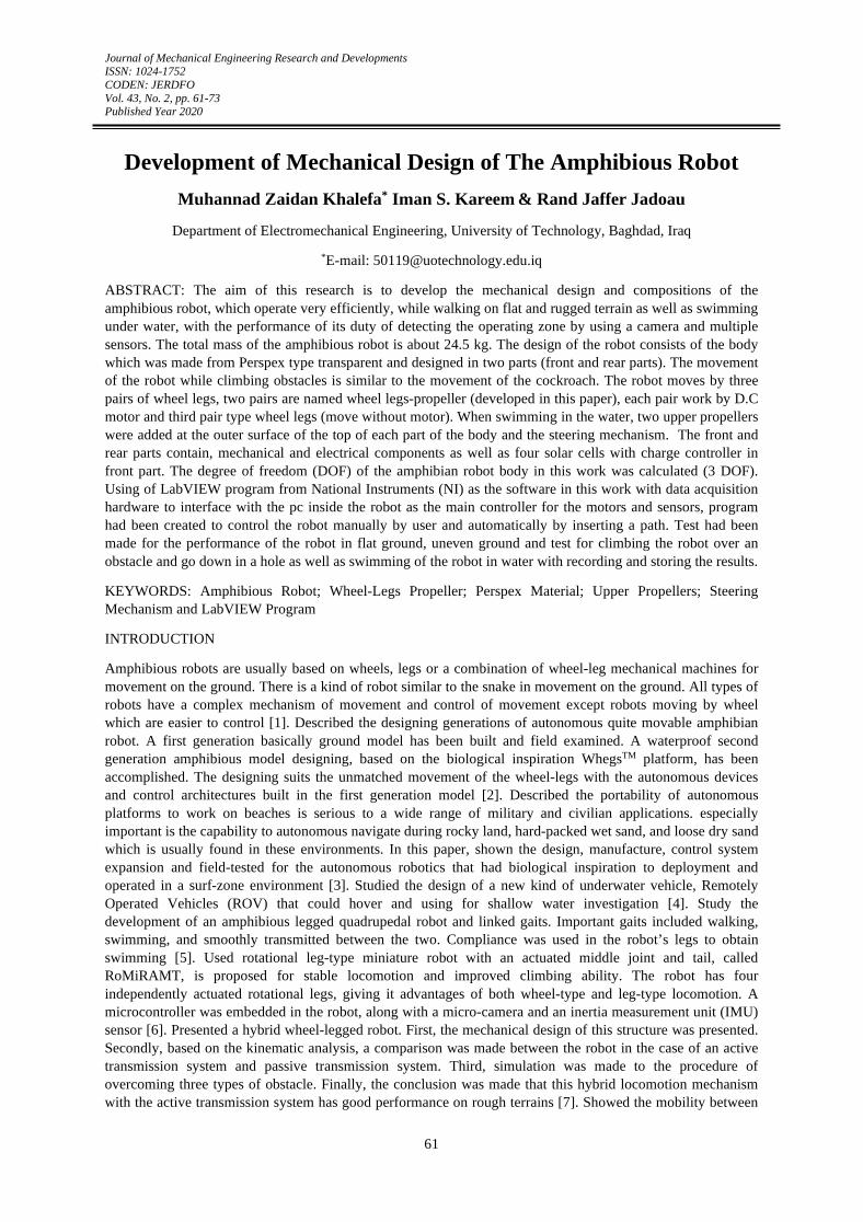
Figure 10 shows the following, the first test of the robot movement was carried out in a straight line on a completely level ground (the floor of the house). The floor was defined by a tape for a distance of 25 meters. The starting line and the finish line were identified. All the results of the processed voltages and the voltages of the working parts were recorded.
Development of Mechanical Design of The Amphibious Robot
68
Figure 10. Movement from the Starting Line for Testing Linear Motion
Operation of the robot and control of the main motors ,front and rear to move the robot within the specified path with the operation of sensors start (gyroscope, accelerometer, magnetometer, barometer and thermometer), results were stored except for Global Positioning System (GPS) results did not appear because of the presence the device inside the house is blocked from picking up the satellite signal where it needs an open space and no roof to pick up the signal from the satellite.
Sandy Ground
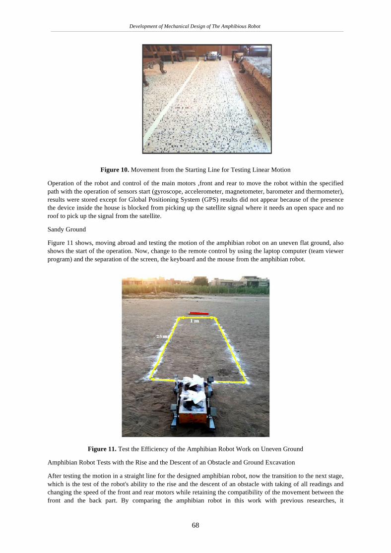
Figure 11 shows, moving abroad and testing the motion of the amphibian robot on an uneven flat ground, also shows the start of the operation. Now, change to the remote control by using the laptop computer (team viewer program) and the separation of the screen, the keyboard and the mouse from the amphibian robot.
Figure 11. Test the Efficiency of the Amphibian Robot Work on Uneven Ground
Amphibian Robot Tests with the Rise and the Descent of an Obstacle and Ground Excavation
After testing the motion in a straight line for the designed amphibian robot, now the transition to the next stage, which is the test of the robot's ability to the rise and the descent of an obstacle with taking of all readings and changing the speed of the front and rear motors while retaining the compatibility of the movement between the front and the back part. By comparing the amphibian robot in this work with previous researches, it

Development of Mechanical Design of The Amphibious Robot
69
characterized by not damaging the surface of the obstacle and can climb and descend any obstacle at a distance of 30 cm with the external diameter of the calf wheel as well as having two motors for each part in case of malfunction occurs in one of the motors can continue the movement of the robot well.
The climbing of the amphibian robot for any obstacle depends on the following, as shown in Figure 12:
i-Any obstacle will be passed on without any damage to the body of the robot, if obstacle bears the weight of the robot.
ii- Climbing is similar to the climb of the insect for any obstacle or walls, that depends firstly on the contact point between the legs and the obstacle, secondly on the angle of foot wheel as well as friction coefficient of rubber material covering the feet.
iii-This Figure 12 shows the climbing of the obstacle as shown in line (3) and the joint in line (2) remains on the ground, the joint angle increases to the extent that allow the front part to reach the height of 17 cm while the rear part remains on the ground .
Figure 12. Climbing of the Amphibian Robot for Obstacle
Figure 13 shows the friction angle between the edge of the obstacle with the middle wheel legs located at the rear part of the robot. This angle will help smoothly to push both front and rear parts.
Figure 13. Friction Angle Between the Edge of the Obstacle
The Figure 14 shows the rise of the front part and the middle wheel legs and taking the horizontal position, while retaining the rear wheel legs out of the obstacle surface (on ground).

Development of Mechanical Design of The Amphibious Robot
70
Figure 14. The Front Part of the Robot has been Fully Raised
Figure 15 shows the rise of two parts completely on the surface level flat of obstacle and now the robot ready to receive the edge of the obstacle to get off.
Figure 15. The Entire Amphibian Robot is on the Obstacle Surface
The descent of the front wheel legs from the height of the obstacle is not the status of jumping, but in the case of regular movement and full balance, this is good for the performance. The internal contents(components and wires) of the amphibian robot continuous operation without any delay, as shown in Figure 16.
Figure 16. The Descent of the Leg Front Wheel from the Obstacle
A set of middle wheel legs to get out of the obstacle will continue to descend, as shown in Figure 17.
Figure 17. The Amphibian robot Continues to Descend Completely from the Surface of the Obstacle
Tests of Amphibious Robot in Water

Development of Mechanical Design of The Amphibious Robot
71
Figure 18 shows the test for the position of the robot (without upper propellers) in the water where it floats only (without running), firstly to ensure that the water does not leak to the inside for one hour, to prevent leakage, the insulator (O-ring) in both of the two parts and water-resistant silicone under the (O-ring) were used, while for the holes surrounding the robot bodys adhesive material was used, as well as the use of a rubber tube (which is the way of inserting the wires for both of the two parts) and secondly to check the satbility (Longitudinal and transverse) of the robot inside the water, to ensure that the distribution of loads within the robot was correct.
Figure 18. Tests for Leakage and Stability
Figure 19 shows the starting of the robot swimming inside the water for more than twenty minutes. During the swimming period, the performance of the robot was controlled and all readings from the gyroscope were recorded and both of front and rear wheel legs-propellers were controlled by changing the voltage. The motion that has occurred in the wheel legs proves that it works as a high efficiency propeller in straight line and while rotating left or right (used mechanical steering), wheel legs only move forward.
Figure 19. The Starting of the Robot Swimming
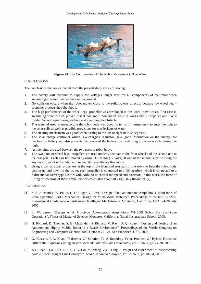
Figure 20 shows the continuation of the robot movement in the water with the control of the speeds of the front and rear motors of wheel legs-propeller, the test includes the process of recording and storing results in computer.
Development of Mechanical Design of The Amphibious Robot
72
Figure 20. The Continuation of The Robot Movement in The Water
CONCLUSIONS
The conclusions that are extracted from the present study are as following:
1. The battery will continue to supply the voltages longer time for all components of the robot when swimming in water than walking on the ground.
2. No collision occurs when the robot moves close to the solid objects directly, because the wheel leg –propeller protects the robot body.
3. The high performance of the wheel legs -propeller was developed in this work in two cases, first case in swimming water which proved that it has good momentum while it works like a propeller and like a rudder. Second case during walking and clamping the obstacle.
4. The material used to manufacture the robot body was good, in terms of transparency to enter the light to the solar cells as well as possible provisions for non-leakage of water.
5. The steering mechanism was good when turning to the left or right (0 to12 degrees). 6. The solar charge controller which is a charging regulator, gave good information on the energy that
reaches the battery and also prevents the power of the battery from returning to the solar cells during the night.
7. Active joints are used between the two parts of robot body. 8. The two pairs of wheel legs- propellers are used models, one pair in the front wheel and the second one in
the rear part . Each pair has moved by using D.C motor (12 volts). If one of the motors stops working for any reason, robot will continue to move rely upon the another motor.
9. Using a pair of upper propellers at the top of the front and rear part of the robot to help the robot body getting up and down in the water, each propeller is connected to a DC gearbox which is connected to a bidirectional Drive type L298N with Arduino to control the speed and direction. In this work, the force of lifting or lowering of these propellers was calculated about 38.7 kg (Only theoretically).
REFERENCES
[1] S. B. Alexander, W. Philip, D. Q. Roger, V. Ravi. “Design of an Autonomous Amphibious Robot for Surf Zone Operation: Part I Mechanical Design for Multi-Mode Mobility”, Proceedings of the IEEE/ASME, International Conference on Advanced Intelligent Mechatronics Monterey, California, USA, 24-28 July 2005.
[2] L. W. Jason. “Design of A Prototype Autonomous Amphibious WHEGS Robot For Surf-Zone Operations”, Thesis of Master of Science, Monterey, California. Naval Postgraduate School, 2005.
[3] H. Richard, D. Thomas, S. B. Alexander, B. Richard, V. Ravi, D. Q. Roger. “Design and Testing of an Autonomous Highly Mobile Robot in a Beach Environment”, Proceedings of the World Congress on Engineering and Computer Science 2008, October 22 - 24, San Francisco, USA, 2008.
[4] G. Hussain, R.A. Khan. “Existence Of Solution To A Boundary Value Problem Of Hybrid Fractional Differential Equations Using Degree Method”. Matriks Sains Matematik, vol. 1, no. 1, pp. 24-28, 2018.
[5] X.C. Tian, Q.H. Li, C.S. He, Y.G. Cai, Y. Zhang, Z.G. Yang. “Design and experiment of reciprocating double Track Straight Line Conveyor”. Acta Mechanica Malaysia, vol. 2, no. 2, pp. 01-04, 2018.

Development of Mechanical Design of The Amphibious Robot
73
[6] M.S. Ibrahim, S. Kasim, R. Hassan, H. Mahdin, A.A. Ramli, M.F. Md Fudzee, M.A. Salamat. “Information Technology Club Management System”. Acta Electronica Malaysia, vol. 2, no. 2, pp. 01-05, 2018.
[7] F. Qiao. “The Study on The Integration of Green Architecture and Appropriate Technology”. Engineering Heritage Journal, vol. 2, no. 2, pp. 01-03, 2018.
[8] B. A. Erman. “Hovering-Mode Control Of The Glider type Unmanned Underwater Vehicle”, Thesis of Master of Science, Institute of Technology, İzmir, 2011.
[9] R. V. Andrew. “Design of Compliance Assisted Gaits For A Quadrupedal Amphibious Robot”, Thesis of Master of Science, the University of Maryland, College Park, 2013.
[10] K. Bokeon, B. Joonbum. “Design and Analysis of a Rotational Leg-type Miniature Robot with an Actuated Middle Joint and a Tail (RoMiRAMT)”, International Conference on Intelligent Robots and Systems (IROS) Congress Center Hamburg, Germany, Sept 28 - Oct 2, 2015.
[11] Z. Change, L. Jinhao, E. G. Tony, Z. Zichao, Tao Sh., Z. Jiangwenjie, M. Yuliang, Y. Ming. “Design and Analysis of a Wheel-Legged Hybrid Locomotion Mechanism”, Advances in Mechanical Engineering, Vol. 7, No.11,pp.1–10, 2015.
[12] P. J. Sanal, P. D. Sandra, S. Yadhukrishnan, M. Priyanka. “Unmanned Amphibian Vehicle”, International Journal of Innovative Technology and Research Volume No.3, Issue No.2, February – March, 2015.
[13] G. Balamurugan, V. P. Haridasan. “Autonomous Locomotion of Leg-Wheel Transformation Robot”, Journal of Chemical and Pharmaceutical Sciences (JCPS), Vol. 9, no. 4, 2016.
[14] “Perspex Design Guide For Fabricators Including Design Applications And Technical Properties”, Perspex Distribution Ltd. Registered in England No. 04625370, 2012.
[15] M.Z. Khalefa, I.S. Kareem, R.J. Jadoau. “Development Of Mechanical Design Of The Robot For High Performance With Rechargeable Battery By Solar Cells”, Patent No.5548, Central Organization for Standardization and Quality Control, Baghdad, Iraq, 2018.
[16] R.J. Bucci, E.A. Starke. “Selecting Aluminum Alloys to Resist Failure by Fracture Mechanisms”, Fatigue and Fracture, ASM Handbook, 2002.
[17] E. Sina. “Expanded PTFE Applications Handbook”, 1st Edition, Elsevier, William Andrew, 30th September 2016.
[18] N. Neville. “Bipedal Running with One Actuator per Leg” Master’s Thesis, McGill University, Montreal, Quebec, October 2005.