development of marginal final report · 2020-01-02 · development of marginal fields for offshore...
TRANSCRIPT

Smart Solutions for Engineering, Science and Computing
Development of Marginal Fields for Offshore Nova Scotia
Phase 2 of 2
FINAL REPORT
Martec Technical Report #TR-10-15
June 2010
Prepared for:
Offshore Energy Technical Research Association 5151 George Street
P.O. Box 2664 Halifax, Nova Scotia
B3J 3P7
Martec Limited tel. 902.425.5101
1888 Brunswick Street, Suite 400 fax. 902.421.1923 Halifax, Nova Scotia B3J 3J8 Canada email. [email protected]
www.martec.com
Martec is a member of the Lloyd’s Register Group

REVISION CONTROL
REVISION REVISION DATE 01 June 25, 2010

PROPRIETARY NOTICE This report was prepared under Contract 09.300459 for Offshore Energy Technical Research Association and contains information proprietary to Martec Limited. The information contained herein may be used and/or further developed by Offshore Energy Technical Research Association for their purposes only.


EXECUTIVE SUMMARY The main scope and tasks for this project have been completed, and the envisioned Sable Offshore Minimal Infrastructure Tool (SOMIT) has been developed and issued to NSDOE. The tool is capable of evaluating various subsea and standard production type developments simultaneously for a full evaluation of the development of single- and multiple-SDA developments. The following main tasks of the original scope of work have been completed:
1. Trend Analyses of the Proposed Minimal Structures
2. Evaluation and Development of Subsea Tie Back Development Concepts
3. Evaluation of a Larger Range of Production Process Scenarios
4. Evaluation of Various Field Development Requirements for Offshore Infrastructure
5. Development of the Tool Interface and Output Requirements
6. Develop Schedule of Rates for use in the tool to derive overall infrastructure costs
7. Interface with CNSOPB
While SOMIT fills an informational gap with regard to the evaluation of Nova Scotian SDAs, further study is required in the following areas: Oil Production – to consider oil production, a similar effort would be needed to determine the required equipment and processing for the production types anticipated for Nova Scotia Offshore. Drilling – this remains the largest portion of the overall development costs, and was not considered in great detail in the current study’s scope of work. Therefore, the estimation of this cost is based on high-level analysis only. An evaluation tool should be created to suit SOMIT, which could be based on SDA reservoir and geological information, and present drilling/well production options and costs for the various SDAs. As the most expensive portion of the overall field development cost, drilling represents the largest impediment to development of Nova Scotia’s SDAs. Deep Water – the scope of the current study has focused on the known reserves, and, therefore, has been limited to shallow water development. Much of Nova Scotia resource potential lies in water depths of >500m. Infrastructure required to explore and develop resources at such depths are far different from those used at the shallower depths.

TABLE OF CONTENTS
1.0 INTRODUCTION.....................................................................................................................................1 1.1 PHASE 1 OF 2 - FEASIBILITY OF MINIMAL STRUCTURES OFFSHORE NOVA SCOTIA ................................1 1.2 PHASE 2OF 2 - SABLE OFFSHORE MINIMUM INFRASTRUCTURE TOOL .....................................................2
2.0 PHASE 2 ....................................................................................................................................................5 2.1 TREND ANALYSIS ....................................................................................................................................5 2.2 EVALUATION AND DEVELOPMENT OF SUBSEA TIE BACK DEVELOPMENT CONCEPTS .............................6 2.3 EVALUATION OF A LARGER RANGE OF PRODUCTION PROCESS SCENARIOS ............................................6
2.3.1 Production Types...............................................................................................................................6 2.3.2 Production Types Not Included .........................................................................................................7
2.4 EVALUATION OF VARIOUS FIELD DEVELOPMENT REQUIREMENTS FOR OFFSHORE INFRASTRUCTURE....7 2.5 DEVELOPMENT OF THE TOOL INTERFACE AND OUTPUT REQUIREMENTS ................................................8 2.6 DEVELOP SCHEDULE OF RATES FOR USE IN THE TOOL TO DERIVE OVERALL INFRASTRUCTURE COSTS.8 2.7 INTERFACE WITH CNSOPB.....................................................................................................................8
3.0 DISSEMINATION AND TECHNOLOGY TRANSFER....................................................................10
4.0 CONCLUSIONS AND RECOMMENDATIONS ................................................................................11
5.0 PUBLICATIONS ....................................................................................................................................12
APPENDIX A: FIELD LAYOUTS APPENDIX B: PRODUCTION DESIGN BRIEF APPENDIX C: PRODUCTION EQUIPMENT LISTS APPENDIX D: PROCESS DIAGRAMS APPENDIX E: COST ESTIMATES APPENDIX F: OTC PAPER 20704 APPENDIX G: OTC 2010 AND NS ENERGY R&D FORUM PRESENTATIONS

LIST OF FIGURES FIGURE 1-1: SINGLE CAISSON STRUCTURE FOR USE IN THE NOVA SCOTIA OFFSHORE ............................................2 FIGURE 1-2: MINIMAL SATELLITE STRUCTURE FOR USE IN THE NOVA SCOTIA OFFSHORE ......................................2 FIGURE 2-1: RESULTS OF TRENDING ANALYSIS FOR OFFSHORE FIXED STRUCTURES ..............................................5
LIST OF TABLES TABLE 2-1: PRODUCTION CASE MATRIX ..................................................................................................................6 TABLE 6-1: BUDGET EXPENDED .............................................................................................................................13 TABLE 6-2: EMPLOYMENT SUMMARY ....................................................................................................................13

Development of Marginal Fields for Offshore Nova Scotia - Phase 2 of 2 1
TR-10-15
1.0 INTRODUCTION
The determination of the economic viability of an offshore development is largely related to the cost of the offshore facility that will extract and distribute the gas. Offshore fields, which have questionable economic viability, are considered ‘marginal fields’. Nova Scotia’s remaining known offshore fields fall into the marginal field category, as the recoverable reserves are not as significant as the Sable Offshore Energy Project or Deep Panuke fields. Other areas of the world have faced similar issues regarding the economics of developing ‘marginal fields’. Some of these fields have become economically viable by reducing the cost of the offshore facility used to extract and distribute the gas or oil. To encourage development of these marginal fields, the Nova Scotia Department of Energy (NSDOE) has been working to reduce development risk and increase resource profitability. Part of this strategy includes development of tools aimed at assisting potential developers in understanding the local resources, and economic environment. One such model that has been created is the Nova Scotia Oil and Gas Exploration Economic Model developed by Indeva. This economic tool provides a cost model for potential developments with respect to life cycle costs, recovery, risk, and potential margins of investment. Prior to 2008, however, no specific work had been completed on the requirements associated with the physical infrastructure that new development would require. Therefore, in April 2008, NSDOE awarded Phase 1 of a two-phase project to Martec Limited.
1.1 PHASE 1 OF 2 - FEASIBILITY OF MINIMAL STRUCTURES OFFSHORE NOVA SCOTIA
The reduction in cost of a marginal development is largely attributed to the potential reduction in size of the offshore installation. These types of installations are referred to as ‘minimal platforms’. Minimal platforms may reduce the cost of the facility in a number of ways, including:
• Reduction in steel weight; • Simplified fabrication methods; and • Elimination of Heavy Lift Vessels (HLV).
Phase 1 focused on investigating the known types of minimal platforms and their suitability for use in the harsh environment offshore Nova Scotia. Existing minimal platforms are less robust than standard fixed platforms, as they have been developed for use in relatively calm waters and could be unsuitable for Nova Scotia’s severe wave environment. However, the Phase 1 work has shown that, with some modifications, platforms meeting the minimal platform definition above are suitable for the Nova Scotia wave environment. Figures 1-1 and 1-2 show two of these structures, Single Caisson and Minimal Satellite.

Development of Marginal Fields for Offshore Nova Scotia - Phase 2 of 2 2
TR-10-15
Figure 1-1: Single Caisson Structure for use in the Nova Scotia Offshore
Figure 1-2: Minimal Satellite Structure for use in the Nova Scotia Offshore
In addition to this, Phase 1 work summarized the various Significant Discovery Areas (SDAs) and their general characteristics. Conceptual field development scenarios have been created, as well as fabrication and installation scenarios for the various minimal platform types. All indications from Phase 1 have supported the potential use of several different types of minimal platforms, each offering a different set of capabilities and advantages for field development, collectively presenting a new set of development options within the Nova Scotia Offshore.
To this end, at the request of NSDOE, a technical paper outlining Phase 1 study results was presented by Martec Limited at the OTC 2009 conference in Houston, Texas. Presentation at such a venue was a great opportunity to highlight these new lower-cost options for offshore development in Nova Scotia.
Phase 1 of this two-phase study was completed in Summer of 2009.
1.2 PHASE 2OF 2 - SABLE OFFSHORE MINIMUM INFRASTRUCTURE TOOL
Phase 2 of this study has used the Phase 1 minimal platforms, in concert with production studies, operational and fabrication requirements, and a collection of both existing infrastructure and potentially new infrastructure to determine the cost impact of developing the Nova Scotia marginal fields. To achieve this goal, a cost estimation tool, the Sable Offshore

Development of Marginal Fields for Offshore Nova Scotia - Phase 2 of 2 3
TR-10-15
Minimum Infrastructure Tool (SOMIT), will be developed to provide an estimate of the cost of infrastructure required to develop the marginal SDA’s of the Nova Scotian Offshore. The driving force behind the development of SOMIT was the need to provide basic, yet specific, infrastructure-related data and information which could then be used to estimate the associated costs and outline the physical facilities required for a specific field development. Costs are generated based on a matrix of specified rates and estimated quantities. To complete the SOMIT tool, several tasks were required, namely:
1. Trend Analyses of the Proposed Minimal Structures: Phase 1 work was limited to concept development and testing for a single offshore case study. This Phase 2 task was aimed at determining ranges of applicable use, including trends in required steel, fabrication requirements, limitations and local capabilities, with respect to various production requirements and field locations around Sable Island.
2. Evaluation and Development of Subsea Tie Back Development Concepts: The
exclusive use of subsea tie back developments for the current SDAs was evaluated with regard to required infrastructure, green- and brown-field requirements, production efficiencies and limitations, cost, and operational benefits and risks. The exclusively-subsea options were compared with the minimal platforms and other development concepts presented herein and included in the SOMIT costing tool.
3. Evaluation of a Larger Range of Production Process Scenarios: Phase 1 considered
only three likely scenarios, resulting in equipment, layout, and weight requirements. Many more production scenarios were applicable for offshore Nova Scotia, as well as production modifications for existing offshore platforms.
4. Evaluation of Various Field Development Requirements for Offshore Infrastructure:
This task considered offshore interfield pipeline, umbilical, and brown-field requirements. Phase 1 work was expanded to include possible development scenarios for each of the SDAs, as well as various interfield and export options.
5. Development of theTtool Interface and Output Requirements: This task involved the
development of a user-interface to select relevant costing and infrastructure requirements for a given development. Output includes cost estimates, as well as a description of infrastructure requirements. It is expected that the interface will compliment current NSDOE modeling tools focused on the Nova Scotia Offshore.
6. Develop Schedule of Rates for Use in the Tool to Derive Overall Infrastructure Costs:
This task involved assembling a matrix of various cost and rate information from global and local service companies that is then used to derive the infrastructure costs for a selected development scenario.
7. Interface with Canada Nova Scotia Offshore Petroleum Board (CNSOPB): Interfacing
with CNSOPB was required to ensure that all development and planning scenarios,

Development of Marginal Fields for Offshore Nova Scotia - Phase 2 of 2 4
TR-10-15
including operational requirements, are suitable for use in the Nova Scotian Offshore sector.
With this tool, the user, with specific yet high level input, can quickly generate a viable cost for minimum offshore infrastructure that could be priced locally as well as from foreign sources, and that includes infrastructure developed specifically for the Nova Scotia Offshore industry.

Development of Marginal Fields for Offshore Nova Scotia - Phase 2 of 2 5
TR-10-15
2.0 PHASE 2
The following subsections describe in more detail each task performed during the work and the corresponding results.
2.1 TREND ANALYSIS
A structural trending study was carried out for each of the minimal platform groups identified during Phase 1 to evaluate the structural feasibility of the particular concept for operation in varying water depths and locations around Sable Island. Minimal platform categories studied here include:
1. Caisson - trending carried out based on expansion of Phase 1 study. 2. Braced Caisson - trending carried out based on expansion of Phase 1 study. 3. Barge Assisted Jacket - trending carried out based on expansion of Phase 1 study. 4. Self-Elevating Platform - model was developed to determined range of practicality. 5. Standard Jacket - trend analysis carried out based on existing platform data.
Figure 2-1 below shows the results of the trending study.
Minimal Platforms for Marginal Fields Phase II Trending Analysis
0
1000
2000
3000
4000
5000
6000
7000
8000
0 10 20 30 40 50 60 70 80 90 100
Water Depth (m)
Stru
ctur
al S
teel
(Ton
nes)
Single Caisson
Braced Caisson
Barge-Assisted Jacket
Self-Elevating Platform
Standard Jacket (Alma, NT, SV)
Figure 2-1: Results of Trending Analysis for Offshore Fixed Structures

Development of Marginal Fields for Offshore Nova Scotia - Phase 2 of 2 6
TR-10-15
2.2 EVALUATION AND DEVELOPMENT OF SUBSEA TIE BACK DEVELOPMENT CONCEPTS
Subsea field developments have particular concerns and requirements to overcome to be reliable and cost effective. In this task, field development concepts for the current SDAs were generated based on exclusive use of subsea systems. Viable rates of production, equipment requirements, and brownfield modifications to existing platforms were evaluated, with consideration also given to tie back distances, and their impact on flow assurance. The results of the task were viable subsea development concepts for the current SDAs.
Appendix A contains the resulting single field development options for subsea development. The results of tie back limitations and requirements for equipment and brownfield modifications were transferred to the production and cost rates portion of SOMIT.
2.3 EVALUATION OF A LARGER RANGE OF PRODUCTION PROCESS SCENARIOS
Phase 1 included the evaluation of three production cases, which has been expanded here in Phase 2. Table 2-1 shows the production cases included in the study. Each case also considered an option to include a helideck and saferoom.
Further details of the production cases and results are presented in Appendices B & C.
Table 2-1: Production Case Matrix
Production Rate
MMscfd Type 1 Type 2 Type 3
1 Well 15 Case 1
2 Wells 30 Case 2
4 Wells w/ On Board Power 60 Case 3 Case 5 Case 9
4 Wells w/ Power Cable from CPF 60 Case 6 Case 10
6 Wells w/ On Board Power 90 Case 4 Case 7 Case 11
6 Wells w/ Power Cable from CPF 90 Case 8 Case 12
Helideck / Saferoom - OPTION
Note, some of the preliminary cases were eliminated due to duplication or redundancy.
2.3.1 Production Types
The tie-back facilities configuration has been largely based on the flow assurance scheme used to prevent hydrate formation in the flowlines between the wells and the existing facility where

Development of Marginal Fields for Offshore Nova Scotia - Phase 2 of 2 7
TR-10-15
full gas, condensate, and water treating can be provided. Three different primary configurations were considered in the study. Appendix D contains schematic process diagrams of the various types, as described below:
• Type 1 – No TreatingThis configuration will require the least amount of topsides equipment. For thisconfiguration, wells will produce into a production header. MEG supplied by a pipelinefrom the central processing facility (CPF) will be injected into the production header inquantities sufficient to inhibit hydrate formation. As produced water is not removed fromthe production stream, the MEG will require vacuum distillation type recovery (MEGReclamation) at the CPF. If quantities of produced water are high, then this option will notbe feasible. A topsides HIPPS system may be required to protect the subsea pipeline fromoverpressure.
• Type 2 – Partial TreatingFor this configuration, partial dehydration of gas and condensate is provided at theproduction facility. Water is removed via conventional separation and then treated foroverboard disposal. Like the Type 1 configuration, glycol provided via pipeline from theCPF is injected into the production stream to inhibit hydrate formation in the flowline.However, since free water is removed, less glycol is required and therefore conventionalglycol dehydration at the CPF can be used to regenerate the glycol.
• Type 3 – Full TreatingThis configuration, like the partial treating NUI, removes free water. However, thisfacility includes a glycol contactor and glycol regeneration package, and subsequently doesnot require a glycol supply from the CPF.
2.3.2 Production Types Not Included
The original scope of work included the evaluation of production cases which included the production of oil resources. However, upon commencement of the work, it became apparent that both topsides production and subsea production would require entirely separate and specific equipment studies to understand both gas and oil developments. The scope was therefore modified, with agreement from NSDOE, to focus the work on the production of natural gas reserves.
2.4 EVALUATION OF VARIOUS FIELD DEVELOPMENT REQUIREMENTS FOR OFFSHOREINFRASTRUCTURE
Field development options, including subsea options, have been developed. The conceptual scenarios have mapped out reasonable plans for an entire extraction-to-market case for field development. These form the basis of SOMIT for each of the platform concepts and subsea developments evaluated.

Development of Marginal Fields for Offshore Nova Scotia - Phase 2 of 2 8
TR-10-15
Appendix A contains the resulting single field development options for subsea development.
Note the SOMIT deliverable has incorporated an additional development scenario for multiple SDAs. At the request of NSDOE, additional scope was added to the work to provide an additional evaluation tool for the development of multiple fields during a single development cycle.
2.5 DEVELOPMENT OF THE TOOL INTERFACE AND OUTPUT REQUIREMENTS
SOMIT has been developed in Microsoft Excel 2003 as a protected worksheet application. Excel is widely available to most users and has the functionality required to produce the interactive nature of the tool. Initial development of the input and output requirements began prior the completion of the Phase 2 analysis, to ensure that the tool met with approval.
The first draft of SOMIT was provided to NSDOE on April 22nd, 2010, and the final draft version of SOMIT was provided to NSDOE May 25th, 2010.
2.6 DEVELOP SCHEDULE OF RATES FOR USE IN THE TOOL TO DERIVE OVERALLINFRASTRUCTURE COSTS
As part of the development of the tool, a sample schedule of rates was produced for use in SOMIT. In this task, manufacturers and contractors were solicited for quotations on the field development concept created by the tool. The expectation was to receive rough estimates from fabricators with sufficient detail to construct a table of costs.
Martec used consultant Len Perry to obtain the local fabrication estimates. The results of the schedule of rates can be found in Appendix E, and has been inserted as the default costs in SOMIT.
Costs related to the development of subsea were provided by Cameron Subsea, and can be found in Appendix E. Mustang Engineering, as part of their process production study scope, provided development costs for the various scenarios studied, which have also been included in Appendix E.
2.7 INTERFACE WITH CNSOPB
Once the field development scenarios were initially developed, CNSOPB had the opportunity to review the plans, in particular to comment on issues with operations. As part of the focus of this study, the fact that minimal platforms offer operational as well as structural alternatives/limitations compared to standard practice (i.e., requirement for de-manning of platforms, access requirement, etc.) has been considered. While these have been accepted in other sectors, there may be sensitive changes which would require review and discussion. Involving CNSOPB at this initial stage, and instituting changes or limitations to the

Development of Marginal Fields for Offshore Nova Scotia - Phase 2 of 2 9
TR-10-15
development cases before the major evaluation is started, avoided the use of field development cases which may potentially have been rejected by the CSNOBP.
Martec met with Mr. Bob Hale of CNSOPB in December 2009. At this time, the full scope and vision of the SOMIT project (Phases 1 and 2) were discussed. This included discussions around operations and proposed developments which did not include helicopter access. The CNSOPB would expect any developer or development to meet all safety and risk requirements set out by the regulations, but does not prescribe the form or how operators choose to meet these requirements. Mr. Hale and CNSOPB are committed to review any development proposal which meets the current regulations.

Development of Marginal Fields for Offshore Nova Scotia - Phase 2 of 2 10
TR-10-15
3.0 DISSEMINATION AND TECHNOLOGY TRANSFER
The work completed for the development of SOMIT includes multiple efforts to make local industry and the general petroleum industry aware of the various methods available to develop Nova Scotia’s current offshore resources, including the following.
Offshore Technical Conference (OTC) 2010 A paper was authored and submitted to this international conference held in Houston, Texas, May 3-6, 2010. The paper was presented at the conference via a 20-minute presentation. The paper and presentation have been included in Appendices F & G.
Nova Scotia Energy Research and Development Forum 2010 A biannual event held in Nova Scotia to highlight research and capabilities in energy in Nova Scotia. A 15-minute presentation was prepared and presented during this forum. This can be found in Appendix G.

Development of Marginal Fields for Offshore Nova Scotia - Phase 2 of 2 11
TR-10-15
4.0 CONCLUSIONS AND RECOMMENDATIONS
The main scope and tasks for this project have been completed, and the Sable Offshore Minimal Infrastructure Tool (SOMIT) has been developed and issued to NSDOE. The tool has been designed to evaluate various subsea and standard production type developments simultaneously for a full evaluation of the development of both single- and multiple-SDA developments. The following main tasks of the original scope of work have been completed:
1. Trend Analyses of the Proposed Minimal Structures: Phase 1 work was expanded to
include a range of water depths and multiple structures.
2. Evaluation and Development of Subsea Tie Back Development Concepts: Working
with subsea vendors and engineering contractors, viable subsea development scenarios
were developed and included in SOMIT.
3. Evaluation of a Larger Range of Production Process Scenarios: Phase 2 included the
evaluation of 12 topside (dry) production cases, as well as fully subsea production
cases for natural gas, with estimated production rates of between 15MMscfd and
90MMscfd.
4. Evaluation of Various Field Development Requirements for Offshore Infrastructure:
Phase 1 work was expanded to include field development options for all SDAs. The
SOMIT tool has also been expanded to include the option to evaluate the development
of multiple SDAs within a single development plan.
5. Development of the Tool Interface and Output Requirements: SOMIT has been
completed and delivered to NSDOE, complete with default pricing information.
6. Develop Schedule of Rates for Use in the Tool to Derive Overall Infrastructure Costs:
Data from both local and international sources were evaluated and reported back to
NSDOE, and ultimately included in the cost and rate information for SOMIT.
7. Interface with CNSOPB: Envisioned development and planning scenarios were vetted
with CNSOPB to ensure that the resulting SOMIT evaluations would represent
plausible development strategies for the Nova Scotian Offshore.

Development of Marginal Fields for Offshore Nova Scotia - Phase 2 of 2 12
TR-10-15
While SOMIT fills an informational gap with regard to the evaluation of Nova Scotian SDAs, further study is required in the following areas:
Oil Production – to consider oil production, a similar effort would be needed to determine the required equipment and processing for the production types anticipated for Nova Scotia Offshore.
Drilling – this remains the largest portion of the overall development costs, and was not considered in great detail in the current study’s scope of work. Therefore, the estimation of this cost is based on high-level analysis only. An evaluation tool should be created to suit SOMIT, which could be based on SDA reservoir and geological information, and present drilling/well production options and costs for the various SDAs. As the most expensive portion of the overall field development cost, drilling represents the largest impediment to development of Nova Scotia’s SDAs.
Deep Water – the scope of the current study has focused on the known reserves, and, therefore, has been limited to shallow water development. Much of Nova Scotia resource potential lies in water depths of >500m. Infrastructure required to explore and develop resources at such depths are far different from those used at the shallower depths.
5.0 PUBLICATIONS
The work completed in this scope produced a paper for the Offshore Technical Conference 2010. This paper is reproduced in Appendix F for reference.

APPENDIX A
FIELD LAYOUTS

SsWH1
Export Line to Host
Umbilical with MEG supply Line from
Host (optional)
Option 1a: Full Subsea Multiple Wells
Option 1a Notes:
SsWH – Subsea WellHead, Protection Structure, wellhead and Valve Tree. Chemical InjectionFlow line – Typical 6"dia. Or 8"dia. Line for sweet raw Gas.
Umbilical – Wellhead Communications, power / hydraulic, MEG optional.
Export line - 6"dia. To 8" dia. Export line for raw flow.
Check Pressure rielf system, HIPPS or back at Tie Back Host.SsWH max range to Host: 10km SsWH max range to Host with MEG: 50km

Export Line to Offshore Facility
MEG supp
ly Lin
e from
Offsho
re Fac
ility (
Option
al)
Option 1b: Single Well – Dry Caisson
Option 1b Notes:
WH1 – Dry Tree Caisson Platform WellHead, Flow line – Typical 6"dia. Or 8"dia. Line for sweet raw Gas.MEG Supply Line – Typical 3"dia. Supplly line from tie back platform (Optional will allow increased range)Export line - 6"dia. To 8" dia. Export line for raw flow.
Process:Minimum of Dry Tree and HIPPSOptions for:MEG InjectionTest Separation
WH max range to Host: 10km WH max range to Host with MEG: 50km
WH1


Option 4: Self Elevating Dry Platform (no wells) with Tie-Backs
Option 4 Notes:
This option is an extension of Option 3, with all wells tied back to the new Dry Hub Platform. This diagram shows both subsea and single caisson type wellheads.
Processing – Dry Hub platform would allow for partial or Full processing;Partial Dehydration, water treatment,Power generation (diesel), Pressure relief (small flare), MEG Injection,Metering(Limit is dependant on depth of reservoir and current drilling capabilities)
MEG Supply Line – Typical 3"dia. Supply line from tie back platform (MEG line is not required if reclamation is provided on the platform)
Export line - 8"dia. To 14" dia. Export line for partially treated flow.
Water Depth - Dry Hub platform limit of 60m (Self Elevating?)– subsea extension to deeper waterWells – 1-2 Wells are directionally drilled at Dry Hub up to approximately 8km from platform + well head tie-backs.Increased processing onboard increases flow assurance and max distance to tie-back Host Facility. Could be as much as 100km.
Self Elevating type Platform Hub, would allow for significant processing, No wells at platform.
Dry Platform No Wells
SsWH1
SsWH2
WH3
Export
Line
to
HostMEG su
pply
Line f
rom
Host (O
ption
al)
Interfield Flow Lines(umbilicals for subsea)

APPENDIX B
PRODUCTION DESIGN BRIEF

MARTEC Minimal Topsides Estimating
DESIGN BASIS
0 04 DEC 09 ISSUED FOR DESIGN RCL EAW
A 01 DEC 09 ISSUED FOR REVIEW RCL
REV DATE DESCRIPTION BY CHK PROJECT APP
CLIENT APP

PREPARED FOR: Martec, Limited 1888 Brunswick Street, Suite 400 Halifax, Nova Scotia B3J 3J8 Canada
PREPARED BY: Mustang Engineering 16001 Park Ten Place Houston, TX 77084
PROJECT DOC TYPE DISCIPLINE SEQ. NO Document No
16196 DC UPE 0001

TABLE OF CONTENTS
1. INTRODUCTION 4
1.1 PURPOSE 4 1.2 ABBREVIATIONS 4 1.3 FACILITY TYPES 4 1.4 CASES 5
2. PROCESS DATA 5
2.1 INDIVIDUAL WELL DATA 5 2.2 SPECIAL CONSIDERATIONS 6
3. PROCESS SYSTEMS 6
3.1 PRODUCTION MANIFOLD 6 3.2 GAS/LIQUID SEPARATION 6 3.3 WATER TREATMENT 6 3.4 GAS TREATMENT 7 3.5 CONDENSATE HANDLING 7 3.6 DEPARTING PIPELINE 7 3.7 PIPELINE PIG LAUNCHER 7
4. FLOW MEASUREMENT 8
5. PROCESS UTILITIES 8
5.1 VENT AND RELIEF 8 5.2 DRAINS 8
6. POWER 8
7. CONTROL SYSTEM 9
8. UTILITY SYSTEMS 9
8.1 CHEMICAL INJECTION SYSTEM 9 8.2 CRANES 9 8.3 FIREWATER PUMPS 9
9. HELIDECK 9
10. SAFETY AND LIFE SUPPORT EQUIPMENT 9

1.0 INTRODUCTION
1.1 PURPOSE The purpose of this Design Basis is to establish the assumptions to be made for Mustang Engineering to prepare a cost and weight estimating tool for various types of Normally Unmanned Installations offshore Nova Scotia. These facilities are premised as tie-backs to an existing Central Production Facility.
1.2 ABBREVIATIONS CPF Central Production Facility CPI Corrugated Plate Interceptor FWHP Flowing Wellhead Pressure HIPPS High Integrity Pressure Protection System MEG Monoethylene Glycol NUI Normally Unmanned Installation SCADA Supervisory Control and Data Acquisition SITP Shut-In Tubing Pressure
1.3 FACILITY TYPES The tie-back facilities configuration will be largely based on the flow assurance scheme used to prevent hydrate formation in the flowlines between the wells and the existing facility where full gas, condensate and water treating can be provided. Three different primary configurations will be considered.
1.3.1 Type 1 – No Treating This configuration will require the least topsides equipment. For this configuration, wells will produce into a production header. MEG supplied by a pipeline from the CPF will be injected into the production header in quantities sufficient to inhibit hydrate formation. As produced water is not removed from the production stream, the MEG will require vacuum distillation type recovery (MEG Reclamation) at the CPF. If quantities of produced water are high, then this option will not be feasible. A topsides HIPPS system may be required to protect the subsea pipeline from overpressure.
1.3.2 Type 2 – Partial treating For this configuration, partial dehydration of gas and condensate is provided at the production facility. Water is removed via conventional separation and then treated for overboard disposal. Like the Type 1 configuration, glycol provided via pipeline from the CPF is injected into the production stream to inhibit hydrate formation in the flowline; however, since free water is removed, less glycol is required and conventional glycol dehydration at the CPF is able to regenerate the glycol.

1.3.3 Type 3 – Full Treating This configuration like the partial treating NUI, removes free water. However, this facility includes a glycol contactor and glycol regeneration package and subsequently does not require glycol supply from the CPF.
1.4 CASES The cases to be analyzed are summarized in Table 1. The number of wells refers to the number of production dry tree wells and/or well slots on the facility. The option for a Helideck and an associated Saferoom will be considered. This option will have one cost and weight that can be associated with any of the cases. The facility Types are described in Section 1.3.
Type 1 Type 2 Type 3
1 Well Case 1
2 Wells Case 2
4 Wells w/ On Board Power Case 3 Case 5 Case 9
4 Wells w/ Power Cable from CPF Case 6 Case 10
6 Wells w/ On Board Power Case 4 Case 7 Case 11
6 Wells w/ Power Cable from CPF Case 8 Case 12
Helideck / Saferoom OPTION
Table 1 – Case Matrix
2.0 PROCESS DATA
2.1 INDIVIDUAL WELL DATA The data for each producing well is summarized below. For the various cases summarized in Section 1.4, the number of wells is multiplied by the production rates below to obtain the facility design production rate.
Gas Production Rate 17,700 m3/hr (15 MMscfd)
Condensate Production Rate: 63.8 m3/day (400 BPD)
Water Production Rate 21.2 m3/day (135 BPD)
Total Liquids Production Rate 85 m3/day (535 BPD)
Reservoir SITP < 400 bar (5800 psi)
FWHP < 345 bar (5000 psi)
Wellhead Rating API 5000 or ANSI 2500

2.2 SPECIAL CONSIDERATIONS
Sand Production Minimal - provide sand probes in flowlines
Condensate Emulsion Not anticipated
Hydrates MEG required for inhibition for Cases 1 thru 8
Hydrates not anticipated for Cases 9 thru 12
Paraffin Nil
CO2 Nil
H2S Nil
3.0 PROCESS SYSTEMS
3.1 PRODUCTION MANIFOLD
Cases 1 and 2 Production Header only
No well testing capability
Cases 3 and 4 Production Header and a Test Header
Test Header will contain a 3-phase meter to provide well test capability
Cases 5 thru 12 Production Header and a Test Header
Each header feeds a Separator
3.2 GAS/LIQUID SEPARATION
Cases 1 thru 4 No gas/liquid separation
Cases 5 thru 12 Test Separator sized for 1 well flow rate
Production Separator sized for peak total production rate
3.3 WATER TREATMENT
Cases 1 thru 4 No water treatment.
Cases 5 thru 12 Bulk water removal in the Production Separator
Water treated for disposal overboard via hydrocyclones and secondary treatment (skimmer or CPI)

3.4 GAS TREATMENT
Cases 1 thru 4 MEG from CPF injected into Production Header using Gas/MEG Static Mixer to prevent hydrate formation in departing pipeline. Lean MEG Booster Pumps may be required, but are not preferred.
Cases 5 thru 8 MEG from CPF injected into Production Header using Gas/MEG Static Mixer to prevent hydrate formation in departing pipeline (less MEG injection required due to lack of free water in pipeline). Lean MEG Booster Pumps maybe required.
Cases 9 thru 12 Glycol contactor and glycol regeneration package provided to dehydrate the departing pipeline gas below hydrate formation temperature. This in conjunction with produced water disposal results in the elimination of a need for MEG from the CPF for hydrate inhibition.
3.5 CONDENSATE HANDLING
Cases 1 thru 4 No condensate treating.
Cases 5 thru 12 Primary separation in the Production Separator, followed by a condensate dehydrator prior to reinjection of condensate into departing pipeline
3.6 DEPARTING PIPELINE
Cases 1 thru 4 Carry inhibited (MEG) gas, water and condensate to the CPF. Pipeline size will likely range between 6” and 10”, depending on number of wells.
Cases 5 thru 8 Carry inhibited gas and condensate to the CPF. Pipeline size will likely range between 8” and 10”.
Cases 5 thru 12 Carry dehydrated gas and condensate to the CPF. Pipeline size will likely range between 8” and 10”.
3.7 PIPELINE PIG LAUNCHER
Cases 1 thru 4 Provisions (space/weight) provided for Pig Launcher, but not installed
Cases 5 thru 12 Permanently installed Pipeline Pig Launcher

4.0 FLOW MEASUREMENT
Cases 1 and 2 Three-phase meter on Production Header (total flow, not individual well test)
Cases 3 and 4 Three-phase meter on Test Header
Cases 5 thru 12 Gas, condensate and water meters at Test Separator outlets
Gas allocation meter prior to commingling with condensate at departing pipeline
Condensate allocation meter prior to commingling with gas at departing pipeline
5.0 PROCESS UTILITIES
5.1 VENT AND RELIEF
Cases 1 thru 4 HIPPS used to avoid need for a vent/relief system
Cases 5 thru 12 Full vent/relief system provided. Includes a Relief Scrubber, conventional flare boom, high pressure flare tip and low pressure vent. System will be designed to handle full production rate.
Snuffing system
5.2 DRAINS
Cases 1 thru 4 Open Drain Caisson or Tank and Pumps
Cases 5 thru 12 Hazardous Open Drain Tank and Pumps
6.0 POWER
An electrical control room will be provided for all cases. The size will vary depending on the quantity of loads. Power supply/generation for each case is provided below.
Cases 1 thru 4 On board power generation from a remote power
generator device such as a solar, wind or thermo-electric generator.
Cases 5, 7, 9 and 11 On board power generation from diesel generators
Cases 6, 8, 10 and 12 Power provided by a cable from the CPF

7.0 CONTROL SYSTEM A Wellhead Control Panel will be provided for all cases. This panel will house the SCADA components required for communication/control via the CPF supervisory system.
8.0 UTILITY SYSTEMS
8.1 CHEMICAL INJECTION SYSTEM The chemical injection system shall consist of tote tanks with electric motor driven or hydraulic powered chemical injection pumps. A nominally sized skid will be determined for each case; however, the chemicals required for each case will not be provided.
8.2 CRANES Number of Cranes: 1 Type: HOLD Load Rating: HOLD
8.3 FIREWATER PUMPS None
9.0 HELIDECK A helideck will be considered as an option for each case. The following will be required for a helideck installation.
• Helideck (same size each case) • Temporary Safety Room • HVAC unit
10.0 SAFETY AND LIFE SUPPORT EQUIPMENT Life boats or life rafts will be provided to support

APPENDIX C
PRODUCTION EQUIPMENT LISTS


APPENDIX D
PROCESS DIAGRAMS


APPENDIX E
COST ESTIMATES

SYSTEM DESCRIPTIONUSER-INPUT
COST NOTES
STRUCTURAL INSTALLATIONUNIT COST
($CDN)Steel Procurement/Fabrication Including Piles ($CDN/Tonne) 5,000$
Mobilization & Demobilization of Installation Flotilla (One-Time, Fixed) NIT COST ($CDN) Drilling Rig 2,500,000$ Onshore Crane & Supporting Equipment 500,000$ Construction/Installation Vessel 1,750,000$ For example, 150T heave-compensated w/crane. Including pile-driving capabilities where required. Support Vessel 750,000$ Small Barge (e.g., Caisson Topsides, WHPS) 50,000$ Vessel may be available locally (i.e., mobilization not required) Large Barge (e.g., Hub Topsides) 100,000$ Vessel may be available locally (i.e., mobilization not required) Small Tug 75,000$ Vessel may be available locally (i.e., mobilization not required) Large Tug 150,000$ Vessel may be available locally (i.e., mobilization not required) Heavy Lift Vessel (Traditional Jacket Only) 30,000,000$ Day Rate x 30 days round trip to Sable
Day Rates for Installation Flotilla ($/day)UNIT COST ($CDN/DAY)
Drilling Rig 500,000$ Onshore Crane & Supporting Equipment 125,000$ Construction/Installation Vessel (Subsea Capable) 400,000$ Support Vessel 150,000$ Small Barge (e.g., Caisson Topsides, WHPS) 20,000$ Large Barge (e.g., Hub Topsides) 50,000$ Small Tug 25,000$ Large Tug 60,000$ Heavy Lift Vessel (Traditional Jacket Only) 1,000,000$
Engineering & Project Management (Fraction of Steel) 0.10 During design and installation (not including topsides kit)
SUBSEA MANIFOLD SYSTEMUNIT COST ($CDN) PER
4-Slot 6"x10" Production Manifold (Including Procurement, Assembly, Testing, Insulation, Pigging Loop, Suction Pile Material/Fabrication, Protection Structure, Engineering & Project Management) 10,000,000$ Price to be scaled based on number of incoming flowlines.Hookup & Commissioning (4-Slot Manifold) 1,000,000$ Hookup/Commissioning Cost (default based on 10%) to be scaled based on number of incoming flowlines.
SUBSEA WELLHEAD/TREEUNIT COST
($CDN)Subsea Wellhead & Tree System (Including SIT, Engineering & Project Management) 12,500,000$ Tooling Requirements 4,500,000$ Hookup & Commissioning 1,250,000$ Default cost based on 10% of system cost.
PIPELINE/CABLE INSTALLATIONCOST PER KM
($CDN/km)Materials Procurement/Fabrication Interfield Flowline 175,000$ 6" MEG Injection Line 100,000$ 3" Umbilicals 400,000$ Data power/hydraulics Export Line 350,000$ Power Cable Tie-Back -$ Included in umbilical price
Mobilization of Pipelay Spread (One-Time, Fixed) UNIT COST
($CDN) Pipelay Vessel 5,500,000$ Trenching Vessel 4,500,000$ Typically trenching for EXPORT Line ONLY Survey Vessel 2,500,000$ Pipe Supply Vessel (Incl 10xDayRate in Transit) 625,000$
Day Rates for Pipelay Spread ($/day)UNIT COST ($CDN/DAY)
Pipelay Vessel 550,000$ Trenching Vessel 200,000$ Survey Vessel 150,000$ Pipe Supply Vessel 50,000$
Estimated Pipe Lay Rate (km/day) 3.50Weather Downtime Factor 0.60 The lower the value, the less time lost do to weather.Export Line Trenching (Fraction of Total Length) 0.80Engineering & Project Management (Fraction of Materials) 0.10 Flat rate $137,500 per km also suggested
TOPSIDES ACCESSIBILITY OPTIONSUNIT COST
($CDN) Infrastructure for Boat Access Only 100,000$ To be confirmed.
Restore Default Rates & Costs


APPENDIX F
OTC PAPER 20704 DRY VERSUS WET: AN EVALUATION OF SUBSEA TIE-BACKS AND SURFACE PLATFORM DEVELOPMENT STRATEGIES FOR NOVA SCOTIA

OTC 20704
Dry versus Wet: An evaluation of subsea tie-backs and surface platform Development Strategies for Nova Scotia C. Dunn and P. Rushton; Martec Limited, member of the Lloyd’s Register Group
Copyright 2010, Offshore Technology Conference This paper was prepared for presentation at the 2010 Offshore Technology Conference held in Houston, Texas, USA, 3–6 May 2010. This paper was selected for presentation by an OTC program committee following review of information contained in an abstract submitted by the author(s). Contents of the paper have not been reviewed by the Offshore Technology Conference and are subject to correction by the author(s). The material does not necessarily reflect any position of the Offshore Technology Conference, its officers, or members. Electronic reproduction, distribution, or storage of any part of this paper without the written consent of the Offshore Technology Conference is prohibited. Permission to reproduce in print is restricted to an abstract of not more than 300 words; illustrations may not be copied. The abstract must contain conspicuous acknowledgment of OTC copyright.
Abstract The Nova Scotian Offshore has many discovered fields with low quantities of recoverable resources. These marginal fields will need development plans which require lower capital costs than that of standard development. Other areas of the world have also faced similar issues regarding the economics of developing marginal fields. Some of these fields have become economically viable by reducing the cost of the offshore facility and production used to extract and distribute the gas or oil.
This paper presents the results of the evaluation of a case study of a marginal gas field in the Sable Island area of Nova Scotian Offshore. It provides a comparison of the technologies and strategies that would be used to develop the field for a low production rate, including a direct comparison of an exclusively subsea development with that of a minimal Dry Caisson platform development. The comparison includes costs as well as benefits and disadvantages of each development option.
The evaluation results show that for the case study water depth of 40m, the Dry Caisson platform is suitable for use and provides an option for development with a capital cost far lower than the comparable subsea option. Limitations of access, installation considerations and maintenance of both systems are also compared.
Introduction Currently the Nova Scotian Offshore (NSO) region has many discoveries which could be defined as marginal fields, as shown in Figure 1. Historically, offshore field development for the NSO has used standard large scale and capital intensive infrastructure which would likely be uneconomical for these marginal fields. Minimal platforms and subsea development may provide more cost effective options for future developments.

Figure 1: Sable Island Offshore Areas as defined by current Exploration, Discovery and Production Licenses Minimal platforms typically include a reduction in platform size and weight. These smaller and lighter
platforms may eliminate the requirement for extremely expensive offshore heavy lift vessels. The mobilization of these vessels to the remote NSO can have a huge impact on the cost of a marginal field development. Utilization of innovative transport and installation techniques can eliminate the need for these vessels and greatly reduce the installation costs.
However, the NSO seastate is of significant importance in consideration of the use of minimal platforms. The environmental conditions offshore of Eastern Canada are considered severe. Large waves, high tides, strong currents, high winds, spray ice and cold temperatures are some of the factors to be contended with in the design of an offshore facility. These environmental conditions play a significant role in determining the structural robustness of the facility.
Subsea equipment and development also offers the potential for lower development costs and has been used for the first time in 2009 for field development in the NSO. Subsea development typically requires minimal permanent equipment and therefore does not have significant installation requirements. However, as the development is below the water surface, access to the production equipment is very limited.
Significant Discovery Areas (SDAs)
While several major developments have either been operating or are about to start in the NSO, many potential reserves have not been developed. These fields, which have been explored and delineated to varying amounts, have been designated as Significant Discovery Areas (SDAs) by the local regulatory body, the Canada Nova Scotia Offshore Petroleum Board (CNSOPB). To achieve this status, the licensee of the original exploratory license had to have applied for significant discovery designation. The SDAs are presented in Table 1.
The SDAs vary in recoverable assets from 5Bcf to 450Bcf for Gas, and 23MMBbl to 52MMBbl for oil (CNSOPB 2000). The seabed geology is nearly entirely dense sand, with a potential for a clay layer to appear within the first 100m below the seabed. The water depths vary from 0m (West Sable, which initially was drilled

from Sable island itself) to 125m. A map of the NSO licenses is provided in Figure 1. It is these locations to which future minimal development will apply.
Table 1: Significant Discovery Areas for NSO
General Location SDA #
Common Name
Current Owner Sept-08 Latitude Longitude
Depth
2255P Citnalta ExxonMobil 44-08-45 59-37-30 95m
2286 Chebucto ExxonMobil 43-38-00 59-41-00 86m
2255D Intrepid ExxonMobil 43-52-00 59-53-00 44m
2255Q West Venture ExxonMobil 44-02-00 59-40-00 <20m
2255R Olympia ExxonMobil 44-03-00 59-48-00 50m
2238B West Olympia ExxonMobil 44-02-00 59-53-00 50m
2298 Uniake Shell Canada 44-11-30 59-41-00 75m
2283A South Sable ExxonMobil 43-54-00 59-50-00 <20m
2255N Arcadia ExxonMobil 44-05-30 59-35-00 56m
2121 Onondaga Shell Canada 43-44-30 60-12-30 60m
2299A Glenelg ExxonMobil 43-38-00 60-08-00 85m
2255E West Sable ExxonMobil 43-57-00 60-07-30 -
2417 Penobscott Ammonite 44-09-45 60-04-00 125m
2418 Eagle Ammonite 43-50-00 59-34-00 50m
2255L Primrose Gas Shell Canada 44-00-00 59-07-00 100m
2259 Banquereau ExxonMobil 44-10-08 58-34-00 80m
Case Study The purpose of the case study is to evaluate the development of a typical marginal field of the NSO, based upon the current information available on the Sable SDAs. The evaluation will focus on the comparison of dry production on a Single Caisson type structure with a development using subsea equipment.
Tie-Back
The Sable Island area of the NSO has several existing offshore structures with varying types of topsides processing. All the current platforms produce natural gas in various forms including market ready and partially dehydrated 2-phase flow. This study compares the dry and subsea development of a gas field in this region as a tie-back development to an existing gas production host. As such, the tie-back facilities will have a minimum of production capabilities, with the majority of required processing provided by the host. This processing by the host can occur on the initial host platform, or further downstream. It is assumed that the host has;
− spare production capacity to accept 2 phase wet gas from the tie-back (no dehydration at wellhead) − available power if required for the tie-back facility − available deck space for additional control systems − available deck space for additional process or metering equipment required (including separation if
required) − source of MEG for tie-back facilities − available space for required risers, flow lines and umbilicals
Caisson (Braced or Single)
To evaluate the tie-back case using dry equipment, the Single Caisson type structure was used. The Caisson type structure consists of a structural caisson shell which is installed over and around the well conductor casing for the full height of the water column, as shown in Figure 2. The outer caisson shell supports the lateral loading

of the wind and wave action. It also supports the topside weight and operational loads. The well conductor is located within the caisson shell and the limited appurtenances are routed on the outside of the shell.
The single caisson design consists of larger diameter tubes at the mudline, with conical transitions to smaller tubes as the structure rises through the water column. The lower sections are designed for maximum bending, whereas the upper portions are reduced to limit wave loading. The caisson shell is driven into seabed as a single pile, after the well conductor casing has been installed by the drilling operations. Within the caisson shell, centralizers ensure that the shell is aligned properly.
The single caisson design is sensitive to soil conditions and particularly to the lateral strength of the soil. For these single caissons, the foundation loading is nearly exclusively lateral loading, as opposed to the typical axial loading of piled foundations. If soil strength is an issue, additional braces can be used to allow for additional piles.

Figure 2: Dry Single Caisson Minimal Platform, 40m of water depth, appurtenances not shown

Subsea
The subsea equipment for this study was chosen to be standard and available from multiple subsea equipment vendors. Figure 3 shows the typical subsea remote wellhead, complete with flow line and umbilical, within the subsea protection structure.
Figure 3: Subsea Wellhead, complete with flow line and umbilical, housed inside subsea wellhead protection structure
Production Case
For the case study, a development of a natural gas field was chosen as this represents the majority of stranded resources in the Nova Scotian offshore (CNSOPB 2000). Table 2 shows the production profile used for the case study. The production rate of 17,700 m3/hr (15 MMscfd) has purposely been set low to allow for the minimal level of facilities to be specified for the development. It is quite likely that increases to production would affect both subsea and dry production in similar fashions. This rate is not indicative of the actual optimal production rate for the Sable SDAs.
The tie-back facilities configuration is based on the flow assurance scheme using MEG to prevent hydrate formation in the flowlines between the well and the host facility where full gas, condensate and water treatment can be provided. The MEG supplied by a pipeline from the host will be injected into the production header in quantities sufficient to inhibit hydrate formation. As produced water is not removed from the production stream, the MEG will require vacuum distillation type recovery (MEG Reclamation) at the host. If quantities of produced water are too high, then in reality this option would not be feasible.

Table 2: Case Study Production Profile
Gas Production Rate 17,700 m3/hr (15 MMscfd)
Condensate Production Rate: 63.8 m3/day (400 BPD)
Water Production Rate 21.2 m3/day (135 BPD)
Total Liquids Production Rate 85 m3/day (535 BPD)
Reservoir SITP < 400 bar (5800 psi)
FWHP < 345 bar (5000 psi)
Wellhead Rating API 5000 or ANSI 2500
Sand Production Minimal - provide sand probes in flowlines
Condensate Emulsion Not anticipated
Hydrates MEG required for inhibition
Paraffin Nil
CO2 Nil
H2S Nil
NSO Metocean Conditions
While the environmental conditions will be different for every site considered, the Sable region of the NSO has several consistent features. The area has consistent soil of dense sand layers, with a periodic layer of firm clay. For the purposes of this study the soil was assumed to be dense sand, ideal for driven pile performance. Another feature of the Sable region is the accretion of spray ice and severe wave loading. While a common design criterion for spray ice and wave loading is not available for the region, Table 3 shows the spray ice and Table 4 shows the metocean criteria used for this case study, as suggested by Dunn et al. (2009).
Water depth is critical to the loading of the Caisson Structure. For the case study the water depth was chosen as 40m (131ft). This represents a depth of water at many of the Sable SDA locations (CNSOPB 2000).
For the consideration of flowline and umbilicals, the distance between the remote tie-back wellheads was taken as 10km (6.2 miles) to the host platform. At this distance flow assurance should be achievable with hydrate inhibition alone.
Reservoir pressure and temperatures were assumed to be within typical equipment ranges, with no requirement for high pressure/ high temperature considerations.
Table 3: Wave Study Spray Ice
Elevation Thickness (mm)
25m above MSL 0
10m above MSL 24
8m above MSL 144
5m above MSL 300
4m above MSL 300
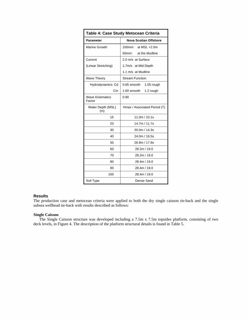
Table 4: Case Study Metocean Criteria
Parameter Nova Scotian Offshore
Marine Growth 100mm: at MSL +2.0m
50mm: at the Mudline
Current
(Linear Stretching)
2.0 m/s at Surface
1.7m/s at Mid Depth
1.1 m/s at Mudline
Wave Theory Stream Function
Hydrodynamics: Cd
Cm
0.65 smooth 1.05 rough
1.60 smooth 1.2 rough
Wave Kinematics Factor
0.90
Water Depth (MSL) (m)
Hmax / Associated Period (T)
15 11.0m / 10.1s
20 14.7m / 11.7s
30 20.0m / 14.3s
40 24.0m / 16.5s
50 26.9m / 17.9s
60 28.2m / 19.0
70 28.2m / 19.0
80 28.4m / 19.0
90 28.4m / 19.0
100 28.4m / 19.0
Soil Type Dense Sand
Results The production case and metocean criteria were applied to both the dry single caisson tie-back and the single subsea wellhead tie-back with results described as follows:
Single Caisson
The Single Caisson structure was developed including a 7.5m x 7.5m topsides platform, consisting of two deck levels, in Figure 4. The description of the platform structural details is found in Table 5.

Table 5: Single Dry Caisson Results 40m of water depth
Caisson Structural Shell weight 218 tonnes
Maximum shell diameter 2400mm
Minimum shell diameter 915mm
Topsides Structure weight 26 tonnes
Topsides Equipment Weight 9 tonnes
Topsides Bulks Weight 17 tonnes
Topsides Estimated Deck Area 101 m2
Topsides deck 7.5m x 7.5m
Figure 4: Dry Single Caisson case study topsides, complete with wellhead, control unit, generator, MEG injection, HIPPS, Wind&solar power, 100m2 of useable deck space
The topside equipment list and process (Figure 5), allowing the platform to meet the production profile and
case study requirements for a remote tie-back are as follows;

Single Caisson Equipment List Production Well Control Panel
Dry Single Caisson Remote Wellhead
Drain Sump Tank
Sump Oil Pump
Water Overboard
MEG SUPPLY
Prod. Hdr.
HIPPS
HIPPS systems
Gas Pipe line Pig Launcher (allowed space only)
Open Drains Tank
Open Drains Pumps
Methanol Injection Skid
Nav Aids
Escape Capsule
15 to 25 kW Generator (or Wind, solar, battery)
Small Diesel tank
Process Control System
Well control panel
Emergency Shut Down System
Telecommunications System (Microwave)
Offskid Valves and Instruments
Crane (2 tonne)
Piping Figure 5: Dry Single Caisson process diagram Piping Supports
Cable Tray
The equipment provides the minimal process and flow assurance required to meet the case study requirements and results in a topside deck requirement which can be met by the Single Caisson platform. The topsides offshore lift weight of less than 60 tonnes will be low enough to allow for standard construction vessels to install the topsides without need of specialized installation equipment or vessels.
The Single Caisson platform does not include helicopter access nor does it have temporary facilities for personnel. This is unlike current unmanned platforms in the Sable Island area which use helicopter access as the main means for maintenance and inspection. Boat would be the main form of access to the Single Caisson topsides, either though man basket type transfer or specialized heave compensated access gangways. The topsides can also be accessed by workover or construction vessels during more intensive maintenance or workover campaigns.
Subsea
The subsea system and equipment chosen to meet the case study requirements are shown below, and shown in Figure 6:
Wellhead 30" Low pressure housing 18 3/4" High pressure housing 13 3/8" Casing hanger bottom BOX Master Wear bushing Wear bushings Temporary abandonment cap Seal Assembly 10,000 psi, Standard weight Emergency Seal Assembly 10,000 psi, Standard weight Horizontal Spool Tree SpoolTree, 10,000psi, With Pigging Loop.

6" CVC Pressure Cap for CVC hub on Tree ASSEMBLY PLET Components Assembly, hub & Receiver structure, 9" GV (manual) 10" Pressure Cap CVC Jumper Kits Topsides Equipment / Topsides Controls (ss only, does not include power / hydraulic supply or brownfield to accept product) Subsea Distribution Equipment Tree Mounteded Controls Hydraulic Flying Leads Electrical Flying Leads Controls Subsea Instrumentation Controls Test Equipment SIT Testing
Flow assurance is provided in a similar fashion to the Dry Caisson option, with MEG being supplied by the
host facility and injected into the flow at the wellhead. The subsea system does not have HIPPS specified, and therefore the host would have to ensure direct access to Venting system to provide pressure relief. The equipment list also does not include specialized tooling equipment. For the completions of the wellhead, and the installation of the tree and subsea commissioning, specialized tooling is required by the drilling contractor. In most cases this is supplied by the subsea equipment vender. However, it is also possible for drilling contractors to meet some of the tooling requirements through pre-owned tools or rental.
Unlike the Dry Caisson, the subsea wellhead system does not need open drains, pumps or power generation for operation, and therefore the system is much simpler. It consists only of a subsea wellhead completion, subsea valve tree and injection into the production flow line. The subsea system will require an umbilical which will carry, in this case, hydraulic fluids to operate the valves and controls on the subsea equipment, data transmission, power and MEG fluids.
Figure 6: Subsea Wellhead, complete with flow line and umbilical, tied back to fixed platform.
Cost Comparison
A detailed cost comparison was completed on both the Dry Caisson and the subsea system based on the equipment as specified above. The high level results are shown in Table 6 below:

Table 6: Case Study Cost Evaluation
Single Caisson Subsea Wellhead
Caisson Shell and substructure, Wellhead protection $1,100,000 $200,000
Topsides equipment and structure $2,925,000 -
Boat Access Provision $100,000 -
Subsea Equipment (no tooling) - $12,500,000
Total $4,125,000 $12,700,000
The costing does not include;
− Subsea tooling − Installation costs for pipeline, subsea, caisson installation, caisson topsides installation − Commissioning and hookup − Brownfield costs at the host platform − Flow Line, MEG line or umbilical
For this very simplified process case, which includes effectively no processing, the cost of the subsea
equipment was found to be far greater than the combined costs of the dry equipment and platform structure. However, with the requirement of additional equipment and systems for the dry caisson, it can be assumed that increased maintenance will be required in comparison to the subsea option. The amount and effort required for the maintenance of the dry caisson would be difficult to estimate and would depend greatly on the composition of the raw gas and the reservoir behavior and production plan.
A key additional capital cost for both development methods is the provision of the Flow lines, MEG line or umbilical. The cost of this essential infrastructure is dependant upon the options for installation and seabed conditions. The fact that the subsea option would use some form of umbilical makes a cost comparison difficult. This is due to the fact that umbilicals are typically custom designed and manufactured for the specific application. However, the cost of installation of the lines by far exceeds the cost of the procurement of the lines. Therefore, the installation of one expensive umbilical could be as cost effective as the installation of two inexpensive standard rigid lines. In general terms, it is estimated that the cost to procure and install the flow lines required for the 10km tie-backs would be in the order of $10-$15 million.
Both the subsea and dry caisson will require equipment and hookup at the host facility. The costs of such work are not included herein, as they are not possible to estimate without acute knowledge of the host and the precise requirements of the remote wellhead. For comparative purposes, both systems would have similar requirements on a host. Both would require control units, power, access to pigging systems, access to production systems and MEG supply. The subsea system would require venting access and hydraulic control unit. Both would require the host to install MEG Reclamation.
Operational /Installation Considerations
Installation While installation costs have not been included, it is anticipated that the costs would be similar for both. A
drilling platform can install both systems with minimal specialized equipment, with the exception of the subsea tooling. For the specified subsea equipment above, the tooling costs were estimated at $16 million to acquire the entirety of the tooling requirements from the vender.
In many cases however, the drilling contractor can provide some or all of the tooling as part of the drilling and well completion fees.
Installation of the flowlines, MEG line and umbilical would be completed by similar vessels, with the lines likely being installed at the same time as a bundle. It could also be that the umbilical for the subsea option would contain all required lines, including flow line, MEG, hydraulic, and data, simplifying the installation process.

Maintenance and Access As indicated above, it is anticipated that the Dry Caisson will require more maintenance than the subsea
system. In fact, many subsea systems are being installed with the design intent of having no major maintenance or intervention for the duration of the production life. This is logical, as access to the subsea system is naturally very limited.
Access to the Dry Caisson platform here-in, however, is also limited to boat access only. In consideration of seasonal weather of the NSO, it would be expected that access to the platform would be limited to the summer season only, as wave conditions would be significant during the remainder of the year. Therefore, the systems on board will have to be robust enough to operate with little to no maintenance for up to one year. The power requirements for the Dry Caisson systems specified for the case study are quite low, and therefore renewable power generation (wind and solar) are expected to be able to support the operations indefinitely. An emergency generator has been specified, but the supply of fuel would depend on supply vessel access. A remote refueling system has not been included, but could be considered as these are in use in the NSO area currently for the unmanned platforms.
Annual Inspection for the Dry Caisson would likely be required and would allow for personnel to access the platform for this purpose. The subsea system could also have regular inspection by ROV, provided by the standard support vessels.
Metering With respect to the host and Brownfield cost, it can be expected that some form of metering will be required
(Livingston et al. 2003). Also, as the product being delivered to the host is both gas and condensate, it could also be considered that separation would be required to capture the quantities of both commercial streams of product. While there are meters and systems that can be used without separation, it may be difficult to establish contractual agreement on the consistent quantities of gas versus condensate from the tie-back. Therefore separation should be considered, and could have impact on the Brownfield costs. Separation will require deck space on the host, which could be difficult to provide.
Adding deck space to a host facility, while fairly typical practice, is very expensive due to the amount of construction activities offshore. Therefore, the provision of separation for metering must be considered carefully.
Conclusions The case study development and cost analysis has shown that the Dry Caisson Platform has a lower capital cost than a comparable subsea system. However, the Dry Caisson platform has additional mechanical processes on board which will require increased maintenance in comparison to the Subsea development option. Therefore, operational costs between the systems should be compared.
Conclusions of the study suggest that in considering minimal developments for stranded or marginal fields in shallow water depths, developers should consider both the Dry caisson Platform and subsea wellhead as viable development options.
Acknowledgments The authors acknowledge John Dickie of the Nova Scotia Department of Energy for support and funding for this project. Also acknowledged; The Canada Nova Scotia Offshore Petroleum Board, for their support of this work, in particular the efforts of Carl Makrides and Bob Hale with respect to the current marginal fields status and operational considerations; Richard Livingston and Eric Wensel of Mustang Engineering LP with respect to production requirements and costing; Pete Thompson of Cameron Subsea.
Nomenclature CNSOPB Canada Nova Scotian Offshore Petroleum Board dia diameter GoM Gulf of Mexico HLV Heavy Lift Vessel LNG Liquid Natural Gas MEG Methylethylene Glycol MSL Mean Sea Level NSO Nova Scotian Offshore NUI Not Usually manned Installation

SDA Significant Discovery License SOEP Sable Offshore Energy Project tonne metric ton = 1000kg
References
CNSOPB, Technical Summaries of Scotian Shelf Significant and Commercial Discoveries, Canada-Nova Scotia Offshore
Petroleum Board, Halifax, 2000 Dunn, C., DesRochers, C., and MacDonald, G.: Martec Limited, 2009, Minimal Structures for Marginal Fields, OTC 20241,
Houston, May 2009 Livingston, R., Tong, D., Wensel, E. and Whitworth, M.: Mustang Engineering, 2003, Topsides Lessons Learned from Subsea
Tie-Back Projects, OTC 15112, Houston, May 2003

APPENDIX G
OTC POWER POINT PRESENTATION 20704 DRY VERSUS WET: AN EVALUATION OF SUBSEA TIE-BACKS AND SURFACE PLATFORM DEVELOPMENT STRATEGIES FOR NOVA SCOTIA
Similar Presentation used for NS ENERGY RESEARCH FORUM 2010 POWER POINT PRESENTATION


