development of fire mitigation solutions for photovoltaic
TRANSCRIPT

© 2016 Fire Protection Research Foundation
1 Batterymarch Park, Quincy, MA 02169-7417, USA Email: [email protected] | Web: nfpa.org/foundation
Development of Fire Mitigation Solutions for Photovoltaic (PV) Systems Installed on Building Roofs – Ph. 1 FINAL REPORT BY: Joel Sipe, Ph.D. Exponent Menlo Park, CA, USA July 2016

—— Page ii ——

—— Page iii ——
FOREWORD The installation of large PV systems on commercial building roofs is an emerging risk due to a favorable value proposition attracting building owners to install the technology. With these systems, the likelihood of a rooftop fire significantly increases since electrical breakdown – leading to arc faults, ground faults, and short circuits - can occur anywhere across the system. Any electrical fault can be accompanied by ensuing fire. The rooftop placement is beyond the building fixed fire protection and detection features. This can mean delayed fire detection and no fixed fire protection. In addition, combustible features of the module and other components add fuel to support a fire. Where a fire develops below PV modules, the modules will reflect heat from a fire back down towards the roof enhancing the combustion rate of conventional roof materials. Roof assemblies traditionally considered “noncombustible” become combustible or fast-burning. With these types of systems, the fire service takes a cautious approach as power generated by the panels cannot be turned off. Even at night, fire service scene lighting has been identified as sufficient to generate an electrical shock hazard. Defensive fire service actions – spraying water from a distance - have been found to have reduced impact as the PV panels conceal and shield the fire below. The challenges introduced by this emerging risk require further research. This project is specifically directed at concerns with rooftop fire spread and identifying additional means to limit fire spread to allow the fire service time to implement a responsible final fire extinguishment plan. The overall goal of this research program will be to identify features that mitigate fire spread between and within PV arrays installed on roof tops. This report contains the results of a Phase 1 project with the objective of developing a test plan to explore this topic to be implemented in a later phase. The Fire Protection Research Foundation expresses gratitude to the report author Joel Sipe, Ph.D., who is with Exponent located in Menlo Park, CA, USA. The Research Foundation appreciates the guidance provided by the Project Technical Panelists, the funding provided by the project sponsors, and all others that contributed to this research effort. The content, opinions and conclusions contained in this report are solely those of the authors and do not necessarily represent the views of the Fire Protection Research Foundation, NFPA, Technical Panel or Sponsors. The Foundation makes no guaranty or warranty as to the accuracy or completeness of any information published herein.

—— Page iv ——
About the Fire Protection Research Foundation
The Fire Protection Research Foundation plans, manages, and communicates research on a broad range of fire safety issues in collaboration with scientists and laboratories around the world. The Foundation is an affiliate of NFPA.
About the National Fire Protection Association (NFPA)
Founded in 1896, NFPA is a global, nonprofit organization devoted to eliminating death, injury, property and economic loss due to fire, electrical and related hazards. The association delivers information and knowledge through more than 300 consensus codes and standards, research, training, education, outreach and advocacy; and by partnering with others who share an interest in furthering the NFPA mission. All NFPA codes and standards can be viewed online for free. NFPA's membership totals more than 65,000 individuals around the world. Keywords: photovoltaic, PV panels, PV systems, rooftop PV systems, PV fire risk, rooftop fire spread, fire mitigation for PV Report number: FPRF-2016-10

—— Page v ——
—— Page vi ——
PROJECT TECHNICAL PANEL
Bob Backstrom, UL
Bill Brooks, Brooks Engineering
Charles Picard, SolarCity
Ajay Friesen, SunPower Corporation
Mark Graham, National Roofing Contractors Association
Tim Johnson, TenK Solar
Jim Lathrop, Koffel Associates
Barbara Mentzer, Retired Fire Chief, Hartford, Iowa Fire & Rescue
Chuck Miccolis, IBHS
Matthew Paiss, San Jose Fire Department
Tom Pedersen, IKEA
Larry Sherwood, Interstate Renewable Energy Council
Mark Earley, NFPA Staff Liaison
PROJECT SPONSORS
Property Insurance Research Group: AIG
CNA Insurance FM Global
Liberty Mutual Insurance Tokio Marine Management
Travelers Insurance XL Gaps
Zurich Insurance Group

—— Page vii ——

Final Report Development of Fire Mitigation Solutions for Photovoltaic (PV) Systems Installed on Building Roofs

1600223.000 - 5873
Final Report Development of Fire Mitigation Solutions for Photovoltaic (PV) Systems Installed on Building Roofs Prepared for Casey Grant Executive Director Fire Protection Research Foundation One Batterymarch Park Quincy, MA 02169 Prepared by Joel E. Sipe, Ph.D., P.E., CFEI Exponent, Inc. 149 Commonwealth Drive Menlo Park, CA 94027 June 29, 2016 Exponent, Inc.

1600223.000 - 5873 ii
Contents
Page
List of Figures iv
List of Tables v
Acronyms and Abbreviations vi
Limitations vii
Executive Summary viii
1. Introduction 1
1.1 Solar PV Components 4
1.2 Firesafety Concerns 5
1.3 Fire Incidents Involving Rooftop PV Arrays 6 1.3.1 Bakerfield, CA; April 2009 6 1.3.2 Mt Holly, NC; April 2011 6 1.3.3 Goch, Germany; 2012 6 1.3.4 Lafarge, WI; May 2013 6 1.3.5 Delanco, NJ; September 2013 7 1.3.6 Florence Township, NJ; November 2013 7
2. Review of Fire Test Data 8
2.1 ASTM E108 Test 8
2.2 UL 1703-2012 Test 11 2.2.1 Spread of Flame Test 11 2.2.2 Burning Brand Test 12
2.3 Development of UL 1703-2013 13 2.3.1 Tests on Non-Combustible Roofs 14 2.3.2 Tests on Combustible Roofs 16 2.3.3 UL 1703-2013 17
2.4 Large-scale Testing 19
2.5 Testing of Mitigation Solutions 22 2.5.1 Vertical Flashing 22 2.5.2 Fire Barriers 23

1600223.000 - 5873 iii
2.5.3 Setback 23 2.5.4 Angled Flashing with Setback 23 2.5.5 Screen 23
3. Gap Analysis 24
4. General Parameters for Large-Scale Tests 25
4.1 Test Array Geometry 25
4.2 Ignition Source 29
4.3 Air Flow 30
4.4 Test Instrumentation 31
5. Roof Assemblies to be Tested 33
6. Mitigation Solutions to be Tested 35
7. Test Matrix 36
7.1 Baseline Tests 36
7.2 Evaluation Tests 37

1600223.000 - 5873 iv
List of Figures
Page
Figure 1. Annual new residential and commercial rooftop solar installations.1 1
Figure 2. Typical residential solar PV installation. (Photographs provided by Jeremy Harold [top] and Vincent Tanguay [bottom]; used with permission) 2
Figure 3. Typical commercial solar PV installation. (Photograph from Grant 2013.) 3
Figure 4. Typical utility scale installation. (Photograph shared through Flickr Creative Commons.) 3
Figure 5. Components of a solar PV array. 5
Figure 6. UL 1703 spread of flame test orientation. 12
Figure 7. UL 1703-2012 Burning brand test geometry. Class A brand shown. 13
Figure 8. Spread of flame test performed on a non-combustible roof deck with a non-combustible PV module surrogate installed with zero setback and a 10 inch standoff height. (Photograph from Backstrom et al. 2010.) 15
Figure 9. Spread of flame test performed on non-combustible roof deck with non-combustible PV module surrogate installed with zero setback and a 2.5 inch standoff height. (Photograph from Backstrom et al. 2010.) 15
Figure 10. Modules sagging from heat during the first test with fire ignited between the modules and the roof. 21
Figure 11. Damaged roof after extinguishment of the first test with fire ignited between the modules and the roof. 21
Figure 12. Fire from test with pine straw under the PV modules. 22
Figure 13. Proposed test array and target array geometry. 27
Figure 14. East-west tented module configuration. 28
Figure 15. Configuration with all modules facing in the same direction. 29
Figure 16. Overall proposed test geometry. 31
Figure 17. Baseline test geometry (Tests 1-5). 37
Figure 18. Geometry for Test 6 (Walkways). 38
Figure 19. Geometry for Test 8 (Verical Barriers) 39

1600223.000 - 5873 v
List of Tables
Page
Table 1. Test parameters for ASTM E108 spread of flame test. 9
Table 2. Test parameters for ASTM E108 intermittent flame test. 10
Table 3. Test parameters for ASTM E108 burning brand test. 10
Table 4. Results of modified ASTM E108 spread of flame tests conducted on PV modules installed with a 5-inch standoff height and zero setback on a roof assembly. (Data from Backstrom et al. 2010.) 16
Table 5. Results of the modified ASTM E108 burning brand tests conducted on PV modules installed with a 5-inch standoff height and zero setback on a roof assembly. (Data from Backstrom et al. 2010.) 16
Table 6. Required tests for PV systems per UL 1703-2013. 19
Table 7. 2014 and projected 2015 low slope roofing sales by roof system type. 33
Table 8. 2014 and projected 2015 low slope roofing insulation installation by material type. 34
Table 9. 2014 and projected 2015 low slope roofing deck installation by material type. 34
Table 10. Test matrix. 36

1600223.000 - 5873 vi
Acronyms and Abbreviations
BAPV Building applied photovoltaic BIPV Building integrated photovoltaic BTU British thermal units EPDM Ethylene propylene diene monomer FPRF Fire Protection Research Foundation kW Kilowatts NFPA National Fire Protection Association NRCA National Roofing Contractors Association OSB Oriented strand board PIR Polyisocyanurate, or polyiso PV Photovoltaic PVC Polyvinyl chloride TPO Thermoplastic olefin UL Underwriters Laboratories, Inc.

1600223.000 - 5873 vii
Limitations
At the request of the Fire Protection Research Foundation (FPRF), Exponent prepared this report on the development of fire mitigation solutions for photovoltaic systems installed on building roofs.
Exponent investigated specific issues relevant to this issue as requested by the client. The scope of services performed during the preparation of this report may not adequately address the needs of other users of this report, and any re-use of this report or its findings, conclusions, or recommendations presented herein are at the sole risk of the user. The opinions and comments formulated during this assessment are based on observations and information available at the time of the investigation.
The findings presented herein are made to a reasonable degree of engineering scientific certainty. We have made every effort to accurately and completely investigate all areas of concern identified during our investigation. If new data becomes available or there are perceived omissions or misstatements in this report regarding any aspect of those conditions, we ask that they be brought to our attention as soon as possible so that we have the opportunity to fully address them.

1600223.000 - 5873 viii
Executive Summary
This draft final report is part of a research project aimed at identifying features and solutions that can be used to mitigate fire spread between and within PV arrays installed on roofs. This report contains a brief introduction to rooftop PV array technology, describes several recent large-loss fires involving roof-mounted solar PV arrays, and presents the results of the first three tasks of the project.
Task 1 of this project is the identification of previous fire testing on PV systems installed on building roofs. This report presents data on the current state of standardized testing of roofing assemblies and PV modules, full scale test data on roofing assemblies with solar PV arrays, and testing of mitigation solutions to prevent flame spread on roofs with solar PV arrays.
Task 2 of this project is the establishment of general parameters for large-scale tests, including the array geometry, ignition source, and air flow conditions. Test arrays of 4 by 5 modules and target arrays of 4 by 1 and 1 by 5 modules are expected to satisfy the test objectives. These arrays are expected to allow for appropriate fires to be initiated and the effectiveness of mitigation measures to be evaluated. A gas burner with a gas output that corresponds to a heat release rate that is similar to the fire exposure used for the ASTM E108 spread of flame test is expected to satisfy the test objectives. An air supply comprised of an array of fans with louvers to direct a stream of air towards the test array at a velocity of 12 mph is expected to satisfy the test objectives. This ignition source and these air flow conditions have been shown to be capable of spreading flames across Class A fire rated roofs with PV modules installed.
Task 3 of this project is the establishment of the roof assemblies that will be tested. Roof assemblies constructed from polyisocyanurate insulation on a steel roof deck with single-ply TPO and EPDM membranes are expected to satisfy the test objectives. A review of current industry practices has shown that these assemblies represent the most common low-slope roof being installed.
Task 4 of this project is the development of a test plan to evaluate potential mitigation solutions for limiting flame spread on low-slope commercial building roofs. A test matrix has been developed to evaluate mitigation solutions that include walkways, non-combustible cover board, vertical barriers, gravel ballast, and non-combustible module backing layers.
The test plan that is developed in this report will be implemented in a later phase of the project.
1600223.000 - 5873 1
1. Introduction
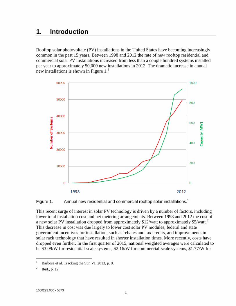
Rooftop solar photovoltaic (PV) installations in the United States have becoming increasingly common in the past 15 years. Between 1998 and 2012 the rate of new rooftop residential and commercial solar PV installations increased from less than a couple hundred systems installed per year to approximately 50,000 new installations in 2012. The dramatic increase in annual new installations is shown in Figure 1.1
Figure 1. Annual new residential and commercial rooftop solar installations.1
This recent surge of interest in solar PV technology is driven by a number of factors, including lower total installation cost and net metering arrangements. Between 1998 and 2012 the cost of a new solar PV installation dropped from approximately $12/watt to approximately $5/watt.2 This decrease in cost was due largely to lower cost solar PV modules, federal and state government incentives for installation, such as rebates and tax credits, and improvements in solar rack technology that have resulted in shorter installation times. More recently, costs have dropped even further. In the first quarter of 2015, national weighted averages were calculated to be $3.09/W for residential-scale systems, $2.16/W for commercial-scale systems, $1.77/W for
1 Barbose et al. Tracking the Sun VI, 2013, p. 9. 2 Ibid., p. 12.
1600223.000 - 5873 2
fixed-tilt utility-scale systems, and $1.91/W for single-axis tracking utility-scale systems.3 Once online, grid-connected residential- and commercial-scale systems that produce more electricity than is consumed by the customer may sell the surplus electricity back to the electric utility through a net metering arrangement.
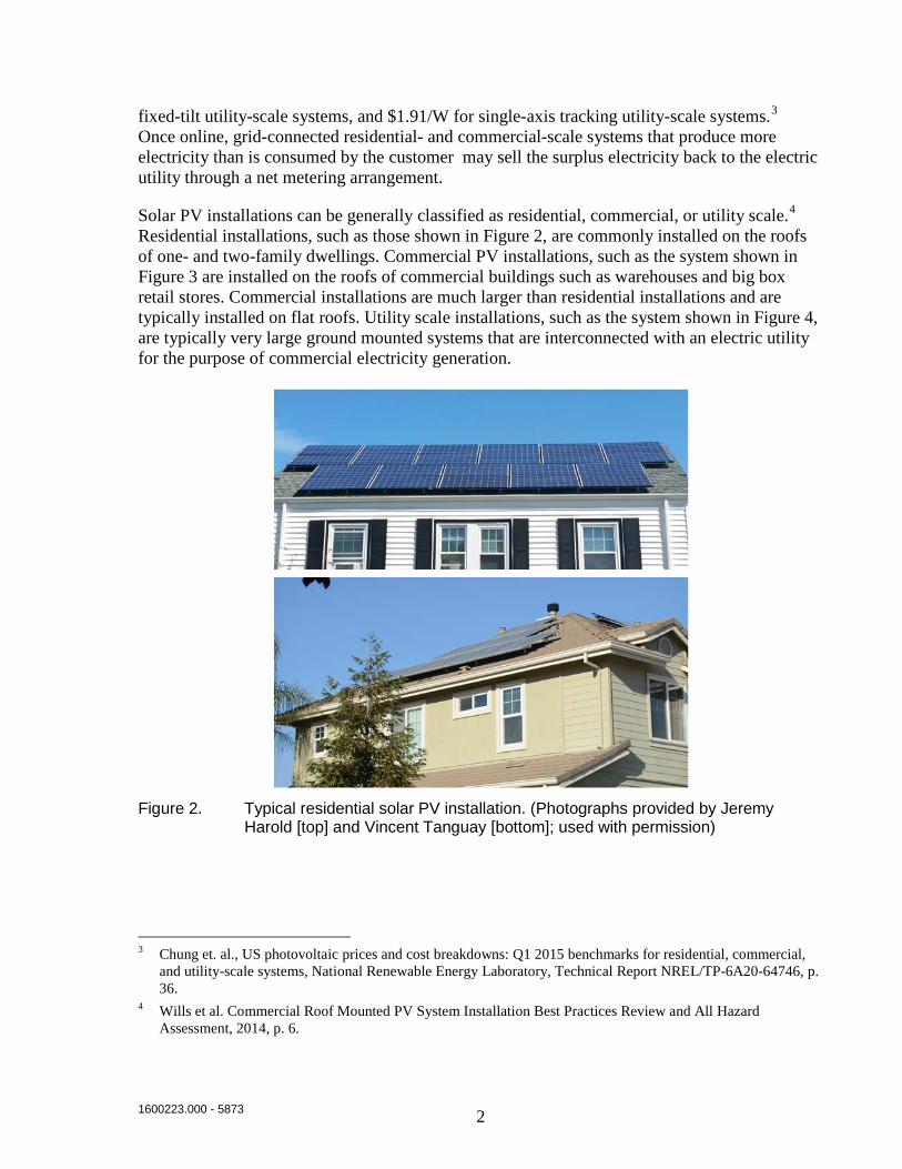
Solar PV installations can be generally classified as residential, commercial, or utility scale.4 Residential installations, such as those shown in Figure 2, are commonly installed on the roofs of one- and two-family dwellings. Commercial PV installations, such as the system shown in Figure 3 are installed on the roofs of commercial buildings such as warehouses and big box retail stores. Commercial installations are much larger than residential installations and are typically installed on flat roofs. Utility scale installations, such as the system shown in Figure 4, are typically very large ground mounted systems that are interconnected with an electric utility for the purpose of commercial electricity generation.
Figure 2. Typical residential solar PV installation. (Photographs provided by Jeremy Harold [top] and Vincent Tanguay [bottom]; used with permission)
3 Chung et. al., US photovoltaic prices and cost breakdowns: Q1 2015 benchmarks for residential, commercial,
and utility-scale systems, National Renewable Energy Laboratory, Technical Report NREL/TP-6A20-64746, p. 36.
4 Wills et al. Commercial Roof Mounted PV System Installation Best Practices Review and All Hazard Assessment, 2014, p. 6.

1600223.000 - 5873 3
Figure 3. Typical commercial solar PV installation. (Photograph from Grant 2013.5)
Figure 4. Typical utility scale installation. (Photograph shared through Flickr Creative Commons.)
Solar PV systems can also be further classified as either roof mounted (sometimes referred to as building applied photovoltaics or BAPV), building integrated photovoltaics (BIPV), shade
5 Grant, C. Fire Fighter Safety and Emergency Response for Solar Power Systems, Fire Protection Research
Foundation Report, October 2013, p. 16.

1600223.000 - 5873 4
structure mounted, or ground mounted.6 BAPV systems, which are installed on the exterior components of buildings, are the most common type of roof mounted systems in the United States. BIPV systems, which incorporate PV modules into the building exterior shell, are less common in the United States, but are more prevalent in Europe. Shade structure mounted systems are commonly installed over carports and parking lots. Ground mounted systems can range from small backyard arrays to large utility scale arrays. This report will focus on commercial BAPV systems.
Roofs, such as those on which BAPV systems are mounted, can be broadly grouped into two categories: low sloped roofs (rise less than 2 in/ft) and steep sloped roofs (rise greater than or equal to 2 in/ft)7. Low and steep sloped roofs will be subjected to different standardized tests that reflect the different installed conditions of the roofs.
1.1 Solar PV Components
Solar PV systems are collections of components that collectively convert solar radiation into electricity. The basic elements of a solar PV system are shown in Figure 5. The most basic component is a solar cell. Individual solar cells are silicon based wafers that each produce approximately 0.5 V. Cells are combined into a module, which is typically a polymer laminate backed glass plate with an aluminum frame. Modules typically produce between 25 and 50 V. Modules are connected in strings using cables.The strings are called panels.8
6 Wills et al. Commercial Roof Mounted PV System Installation Best Practices Review and All Hazard
Assessment, 2014, p. 6. 7 UL 1703-2015, Standard for safety – flat plate photovoltaic modules and panels, Section 31.2. 8 NFPA 70-2014, National Electrical Code, Section 690.1.

1600223.000 - 5873 5
Figure 5. Components of a solar PV array.
1.2 Firesafety Concerns
The widespread installation of solar PV arrays on rooftops has raised concerns over fire hazards that generally fall into two broad categories9:
Fire dynamics – Introducing a solar array onto a fire-rated roof adds additional fuel to the roof structure and also changes the dynamics of fires that develop. PV modules are typically constructed from glass and aluminum frames with polymeric backing materials and encapsulants that add additional fuel load to the roof. In addition to this increased fuel load, if a fire develops on the roof, the presence of the modules can hold the heat closer to the roof and increase temperatures and heat fluxes to the roof.
Ignition hazards – PV systems have multiple potential failure modes that can present ignition hazards. There have been multiple cases where fire causes have been associated with electrical faults in the wiring of PV arrays.
9 Wills, et al. Commercial Roof Mounted PV System Installation Best Practices Review and All Hazard
Assessment, 2014, p. 32.

1600223.000 - 5873 6
1.3 Fire Incidents Involving Rooftop PV Arrays
The rapid increase of installed rooftop solar PV systems over the past 15 years has created new challenges for both the fire service and the code enforcement community. A number of high profile fires have occurred in commercial buildings with rooftop solar PV systems, which has led to changes in fire service tactics and building and fire code requirements. A selection of fire incidents are discussed below.
These fires illustrate some of the challenges presented by rooftop solar arrays on large commercial roof structures. Due in part to these and other fire incidents, there has recently been an increase in the amount of attention focused on best practices for the fire service as well as building and fire code changes associated with solar PV arrays.
1.3.1 Bakerfield, CA; April 2009
In April 2009, a fire occurred in Bakersfield, California on the membrane roof of a Target big-box retail store. The store had a 383 kW array on the roof, which contained 1826 solar PV modules arranged in 166 strings with 11 modules each.10 The fire reportedly started in two locations due to causes associated with a ground fault.11
1.3.2 Mt Holly, NC; April 2011
In April 2011, a fire occurred in Mount Holly, North Carolina on the roof of National Gypsum Company, a drywall manufacturer.12 Similar to the Target fire in Bakersfield, CA, the fire cause was reportedly ground fault related.11
1.3.3 Goch, Germany; 2012
In 2012, a fire occurred at a warehouse in Goch, Germany.13 The fire involved an area of approximately 43,000 ft2 (4,000 m2) and the fire cause was reportedly associated with a defect in the photovoltaic system.
1.3.4 Lafarge, WI; May 2013
In May 2013, a fire occurred in LaFarge, Wisconsin at the corporate headquarters of Organic Valley.14 The construction of the green building and the solar PV system installed on the roof may have contributed to the growth of the fire. The building roof was constructed from
10 Bakersfield Building Department, Memorandum dated April 29, 2009: http://nfpa.typepad.com/files/target-fire-
report-09apr29.pdf 11 The Ground-Fault Protection Blind Spot, Brooks, 2012:
http://www.solarabcs.org/about/publications/reports/blindspot/pdfs/BlindSpot.pdf 12 http://www.wbtv.com/story/14461049/solar-panals-catch-fire-on-factory-rooftop-puzzling-investigators 13 Wills et al. Commercial Roof Mounted PV System Installation Best Practices Review and All Hazard
Assessment, 2014, p. 3. 14 Wills et al. Commercial Roof Mounted PV System Installation Best Practices Review and All Hazard
Assessment, 2014, p. 3.

1600223.000 - 5873 7
lightweight wooden trusses spaced 7 feet, 6 inches on center with standing seam metal roof panels fastened to the trusses. The fire started inside the building and spread to a concealed attic space.15 The building was protected by a wet-pipe sprinkler system and the attic was protected by a dry-pipe system. The fire was able to spread through concealed spaces in the building and the sprinkler system was not effective at extinguishing the fire. At some point in the fire development, the metal roof became energized by the PV system, which inhibited suppression activity by the fire department.
1.3.5 Delanco, NJ; September 2013
In September 2013, a fire occurred in Delanco, New Jersey at a Dietz and Watson warehouse.14 The building was approximately 300,000 ft2 (28,000m2) in size and over 7,000 solar PV modules were installed on the roof. Reportedly, unprotected combustible roofing was a fuel source and allowed the fire to spread. The large solar PV array on the roof reportedly inhibited the ability of firefighters to suppress the fire. The fire burned for 24 hours before it could be suppressed and it consumed the entire building and it’s contents.
1.3.6 Florence Township, NJ; November 2013
In November 2013, a fire occurred in Florence Township, New Jersey on the roof of a Christmas Tree Shop warehouse.16,17 The warehouse was greater than 700,000 ft2 (65,000m2) in size and more than 8,000 solar PV modules were installed on the roof. The fire damaged more than 300 of the solar PV modules. An early notification from an eyewitness allowed for a rapid response and the fire did not enter the building.
15 http://www.nfpa.org/newsandpublications/nfpa-journal/2014/january-february-2014/features/perfect-storm 16 Wills et al. Commercial Roof Mounted PV System Installation Best Practices Review and All Hazard
Assessment, 2014, p. 4. 17 http://www.centraljersey.com/archives/florence-warehouse-fire-extinguished/article_b3cd1e0e-998e-5706-
b36e-83768094c938.html

1600223.000 - 5873 8
2. Review of Fire Test Data
Existing literature related to fire testing of roofs and roof mounted PV systems was reviewed. Information was identified that is relevant to standardized testing of roofing assemblies, tests conducted to simulate fires occurring on roofs, and evaluation of fire mitigation solutions.
2.1 ASTM E108 Test
Building codes in the United States provide requirements18 for fire ratings of roofs as measured by ASTM E108.19 FM Approval Standard 447020 references the test method in ASTM E108 and has similar performance criteria. The ASTM E108 test standard describes a series of tests that include four fire tests:
1. Spread of flame test
2. Intermittent flame exposure test
3. Burning brand test
4. Flying brand test
Roof assemblies intended to be mounted on non-combustible roof decks must only pass the spread of flame test.21 Based on the results of these tests, the roofing assembly is given a fire rating of Class A, B, or C22:
• Class A assemblies are considered to be effective against severe fire test exposures.
• Class B assemblies are considered to be effective against moderate fire test exposures.
• Class C assemblies are considered to be effective against light fire test exposures.23
The ASTM E108 test apparatus consists of an air supply system, gas burner, and test deck. For all of the fire tests, the air supply provides an average air velocity of 1056 ± 44 ft/min which corresponds to 12 ± 0.5 mph (5.3 ± 0.2 m/s).24
18 For example see 2012 International Building Code Section 1505.1. 19 ASTM E108 and UL 790 are equivalent test standards for roofing assemblies. For ease of discussion, the term
ASTM E108 will be used in this report when refering to the tests in those standards. NFPA 256 is a test standard that is also equivalent to ASTM E108 and UL 790, but it was withdrawn in 2008.
20 FM Approval Standard 4470 - Single-Ply, Polymer-Modified Bitumen Sheet, Built-Up Roof (BUR) and Liquid Applied Roof Assemblies for use in Class 1 and Noncombustible Roof Deck Construction.
21 ASTM E108-11 Standard Test Methods for Fire Tests of Roof Coverings, ASTM International, 2011, Section 7.1.
22 ASTM E108-11 Standard Test Methods for Fire Tests of Roof Coverings, ASTM International, 2011, Section 1.2.
23 ASTM E108-11 Standard Test Methods for Fire Tests of Roof Coverings, ASTM International, 2011, p. 1.

1600223.000 - 5873 9
The spread of flame test measures the ability of a fire to spread across the roof surface when exposed to the gas burner. The test parameters for the spread of flame test are shown in Table 1.25 The tests are conducted on a section of a roofing assembly that is 40 inches (1m) wide and 52 inches (1.3m) long,26 except for the spread of flame test, which uses the following lengths for the test roofs27:
• Class A – 8 ft
• Class B – 9 ft
• Class C – 13 ft
The heat release rate of the gas burner is approximately in the range of 21,000-22,000 BTU/min (369-387 kW) for Class A and Class B fire exposures, and in the range of 18,000-19,000 BTU/min (316-334 kW) for Class C fire exposures.28 The gas burner is constructed from a 44 inch long, 2-inch OD steel pipe with a ½-inch by 36 inch slot. Gas is fed to the burner from both ends to provide uniform pressure.29
The roof assembly fails the test if any portion of the roof deck is blown off in the form of flaming or glowing brands that continue to glow after they reach the floor, the roof deck is exposed (for tests with non-combustible decks),30 there is significant lateral flame spread, or the extent of flame spread exceeds the maximum flame spread distance listed in Table 1.31
Table 1. Test parameters for ASTM E108 spread of flame test.
Classification Flame Temperature32
Test Duration33
(min)
Maximum Flame Spread34
(ft)
Number of Tests to Pass35
Class A 1400 ± 50°F (760 ± 28°C) 10 6 2
Class B 1400 ± 50°F (760 ± 28°C) 10 8 2
24 ASTM E108-11 Standard Test Methods for Fire Tests of Roof Coverings, ASTM International, 2011, Section
5.4.4. 25 ASTM E108-11 Standard Test Methods for Fire Tests of Roof Coverings, ASTM International, 2011. 26 Ibid., Section 6.1.1. 27 Ibid., Section 6.1.6. 28 Ibid., Section 5.5.3. 29 Ibid., Figure 1. 30 Ibid., Section 14.2. 31 Ibid., Section 14.4. 32 Ibid., Section 5.5.3. 33 Ibid., Section 9.3. 34 Ibid., Section 14.4. 35 Ibid., Section X4.7.

1600223.000 - 5873 10
Class C 1300 ± 50°F (704 ± 28°C) 4 13 2
The intermittent flame test measures the ability of a roof to resist fire penetration from the exterior of the roof to the underside of the roof deck when exposed to a gas burner. The test parameters for the intermittent flame test are shown in Table 2.36
The roof assembly fails the intermittent flame test if any portion of the roof deck is blown off in the form of flaming or glowing brands that continue to glow after they reach the floor, the roof deck is exposed, or if there is sustained flaming of the underside of the roof deck.37
Table 2. Test parameters for ASTM E108 intermittent flame test.
Classification Flame On (min)
Flame Off (min)
Number of Cycles
Number of Tests to Pass38
Class A 2 2 15 2
Class B 2 2 8 2
Class C 1 1 3 2 The burning brand test measures the ability of the roof assembly to resist an exterior fire attack from a burning wood brand. The test parameters for the burning brand test are shown in Table 3. The roof assembly fails the burning brand test test if any portion of the roof deck is blown off in the form of flaming or glowing brands that continue to glow after they reach the floor, the roof deck is exposed, or sustained flaming is observed on the underside of the roof deck.39
Table 3. Test parameters for ASTM E108 burning brand test.
Classification Brand Mass40 (g) Brands per Deck41 Number of Tests to
Pass42
Class A 2,000 ± 150 1 4
Class B 500 ± 50 2 2
Class C 9.25 ± 1.25 20 2
36 Ibid., Section 8.3. 37 Ibid., Section 14.2 and 14.3. 38 Ibid., Section X4.7. 39 Ibid., Section 14.2 and 14.3. 40 Ibid., Section 10.3. 41 Ibid., Section 10.5. 42 Ibid., Section 10.1.

1600223.000 - 5873 11
The flying brand test assesses the ability of the roof to produce flying brands when exposed to a gas burner. The roof assembly fails the test if flying, flaming brands are produced or particles are produced that continue to glow after reaching the floor.43
2.2 UL 1703-2012 Test
There are currently two fire test standards for roof mounted PV modules: UL 1703 and FM 4478. Prior to 2013, most roof mounted solar PV modules were tested in accordance with UL 1703-2012.44,45 Per this standard, solar PV modules were tested using the same spread of flame and burning brand tests from ASTM E108.46
2.2.1 Spread of Flame Test
The UL 1703-2012 spread of flame test was performed on PV modules in isolation. Modules were oriented such that test flames impinged on the top surface of the module only. The passing criteria for the test was that at no point in the test shall:
a) Any portion of the module or panel be blown off or fall off the test deck in the form of flaming or glowing brands;
b) Portions of the roof deck, or portions of a module or panel intended for installation integralwith or forming a part of the building roof structure, fall away in the form of glowing particles;
c) The flame spread beyond 6 ft (1.82 m) for Class A, 8 ft (2.4 m) for Class B, or 13 ft (3.9 m) for Class C rating. The flame spread is to be measured from the leading edge of the sample; or
d) There be significant lateral spread-of-flame from the path directly exposed to the test flame. Spread-of-flame includes flaming on both the top surface (the surface to which the external flame is applied) and in any intermediate channel, such as the space between stand-off or integral modules and a shingle roof.
The approximate test geometry for the UL spread of flame is shown in Figure 6.47
43 Ibid., Section 14.5. 44 For ease of discussion, the term “UL1703-2012” will be used when discussing editions of the test standard
published prior to 2013 and the term “UL 1703-2013” will be used when discussing editions of the test standard published in or after 2013.
45 FM Approval Standard 4478 is a similar approval document for photovoltaic modules. FM 4478 references the testing performed in ASTM E108, which forms the basis for the UL 1703 fire testing. Additional recommendations from FM Global for photovoltaic module installations are contained in FM Property Loss Prevention Data Sheet 1-15.
46 UL 1703-2002 (revised 2008), Flat-Plate Photovoltaic Modules and Panels, Section 31 – Fire Tests. 47 https://www.dewa.gov.ae/images/smartinitiatives/PV_on_Buildings.pdf

1600223.000 - 5873 12
Figure 6. UL 1703 spread of flame test orientation.
2.2.2 Burning Brand Test
The burning brand test from UL 1703-2012 was also conducted on modules in isolation. The burning brand used was identical to those used in the ASTM E108 burning brand test. Brands were placed on the top surface of the modules. The passing criteria for the test was that at no point during the test shall:
a) Any portion of the module or panel or be blown off or fall off the test deck in the form of flaming or glowing brands;
b) The brand burn a hole through the roof covering or through any part of the module or panel;
c) Portions of a module or panel intended for installation integral with, or forming a part of, the building roof structure fall away in the form of glowing particles; or
d) There be sustained flaming of the module or panel.
The approximate test geometry for the UL 1703 burning brand test is shown in Figure 7.48
48 Ibid.

1600223.000 - 5873 13
Figure 7. UL 1703-2012 Burning brand test geometry. Class A brand shown.
2.3 Development of UL 1703-2013
In 2009, growing concerns were raised from fire and code officials and the solar industry regarding the effects of mounting Class B and Class C fire rated solar PV modules on Class A rated roof assemblies. At that time, both roof coverings and rack mounted PV modules were tested separately and received separate fire ratings. Despite this, little research had been performed to investigate the interaction between PV modules and roof assemblies when PV modules are installed in a standoff configuration over roofing assemblies and exposed to a fire.49 At that time, the UL Online Certification Directory gave the following guidance50:
Installation of modules on or integral to a building’s roof system may or may not adversely affect the roof-covering materials’ resistance to external fire exposure if the module has a lesser or no fire-resistance rating. Roof-covering materials will not be adversely affected when the modules have an equal or greater fire-resistance rating than the roof-covering material.
To address this ambiguity, a series of tests was conducted at UL51 using both combustible and non-combustible roofs,52 and combustible PV modules and non-combustible PV module surrogates. The tests included the spread of flame and burning brand tests from UL 1703.
49 Sherwood et al. Fire classification rating testing of stand-off mounted photovoltaic modules and systems,
August 2013: http://www.solarabcs.org/about/publications/reports/flammability-testing/pdfs/SolarABCs-36-2013-1.pdf
50 Ibid., p. 8. 51 Ibid., p. 9. 52 Backstrom et. al. Effect of Rack Mounted Photovoltaic Modules on the Fire Classification Rating of Roofing
Assemblies, UL Report, November 30, 2010.

1600223.000 - 5873 14
2.3.1 Tests on Non-Combustible Roofs
A series of tests53 was conducted on non-combustible roof decks with and without non-combustible surrogate PV modules installed in a standoff configuration. The surrogate modules were installed on the non-combustible roof deck and temperatures and heat fluxes to the roof deck were measured during spread of flame tests. The tests showed that the presence of a surrogate PV module increased the temperature of the roof deck and increased the heat flux to the roof deck as compared to tests without the surrogate module in place. Tests were conducted at standoff heights of 10, 5, and 2.5 inches (25 cm, 12.5 cm, and 6.25 cm). At standoff heights of 10 and 5 inches (25 cm and 12.5 cm), the flames from the gas burner were captured between the module and the deck. As the standoff height was decreased from 10 to 5 inches (25 cm to 12.5 cm), the measured surface temperatures increased due to a decrease in entrained air. As the standoff height was further decreased to 2.5 inches (6.25 cm), the measured surface temperatures decreased as compared to the test at a standoff height of 5 inches (12.5 cm) due to the fact that not all of the flames were being captured.54 The highest measured temperature and heat fluxes were recorded when the surrogate module was mounted in line with the leading edge of the roof deck. As the setback was increased, the measured temperature decreased.55 Tests of non-combustible PV module surrogates mounted on non-combustible roof decks with zero setback and standoff heights of 10 inches (25 cm) and 2.5 inches (6.25 cm) are shown in Figure 8 and Figure 9.56 It is worth noting that in the test with a 10-inch standoff height, all of the flames from the burner can be seen to extend under the module, while in the test with a 2.5-inch (6.25 cm) standoff height, some of the flames from the burner extend above the module. The flames that extend above the module will contribute much less heat to the flame spread process because much of the heat is transported away from the roof.
53 Ibid., p. 5. 54 Ibid., p. 6. 55 Ibid., p. 7. 56 Ibid., p. 24.

1600223.000 - 5873 15
Figure 8. Spread of flame test performed on a non-combustible roof deck with a non-combustible PV module surrogate installed with zero setback and a 10 inch standoff height. (Photograph from Backstrom et al. 2010.)
Figure 9. Spread of flame test performed on non-combustible roof deck with non-combustible PV module surrogate installed with zero setback and a 2.5 inch standoff height. (Photograph from Backstrom et al. 2010.)

1600223.000 - 5873 16
2.3.2 Tests on Combustible Roofs
Modified ASTM E108 spread of flame tests were conducted using Class A and Class C rated PV modules installed on Class A and Class C rated roofing assemblies. The test results showed that the presence of a PV module adversely affects the fire rating of a roof.55 The results of these tests are shown in Table 4.57
Table 4. Results of modified ASTM E108 spread of flame tests conducted on PV modules installed with a 5-inch standoff height and zero setback on a roof assembly. (Data from Backstrom et al. 2010.)
Roof Rating PV Module Rating Flame Spread
A C > 8 ft (>2.4m)
A A > 8 ft (>2.4m)
C C > 8 ft (>2.4m)
Non-combustible C > 8 ft (>2.4m)
Non-combustible A > 8 ft (>2.4m) ASTM E108 burning brand tests were conducted on Class A and Class C PV modules mounted on Class A and Class C fire rated roofing assemblies.58 Tests were conducted using Class A and Class C burning brands that were placed on either the modules or between the module and the roof (not required per UL 1703-2012). The tests show that in some cases the roofs did not pass the burning brand test when a PV module was mounted on the roof assembly. The results are shown in Table 5.
Table 5. Results of the modified ASTM E108 burning brand tests conducted on PV modules installed with a 5-inch standoff height and zero setback on a roof assembly. (Data from Backstrom et al. 2010.)
Roof Rating PV Rating Brand Size/Position Fire Performance Result
A C Class A/PV Compliant
A C Class A/Roof 2 Compliant/
1 Not compliant
C C Class C/Roof Not compliant
A A Class A/Roof Not compliant
Based on these results, a broad stakeholder group held meetings to discuss what actions should be taken59 and decided that the UL 1703 standard should be revised. A task group was convened 57 Backstrom et. al. Effect of Rack Mounted Photovoltaic Modules on the Fire Classification Rating of Roofing
Assemblies, UL Report, November 30, 2010, p. 7. 58 Ibid., p. 7. 59 Backstrom, B., and D. Sloan. Characterization of photovoltaic materials, critical flux for ignition, UL Report,
January 16, 2012, p. 4.

1600223.000 - 5873 17
under the UL 1703 Standards Technical Panel (STP) to revise the standard to more appropriately evaluate the fire behavior of PV modules as an assembly that includes the intended roof structure. A concern raised by the task group was the quantity of tests that could be required to evaluate possible combinations of PV and roofing systems. It was agreed that while roofing systems could be grouped into low and steep sloped roofs, there are a large number of manufacturers and types of roofing products, which could result in a prohibitive number of required tests. To address this concern, a series of tests was conducted to characterize the flammability characteristics of solar PV module components and typical roofing materials and based on observed similarities in an attempt to minimize the number of required new tests. The critical heat flux for ignition of PV module components and roofing materials was measured in a cone calorimeter per ASTM E1354.60 The measured values were compared to heat flux values that were measured on non-combustible roofs with and without a non-combustible surrogate module installed in a standoff configuration during an ASTM E108 spread of flame test. The test results showed that:
• Heat fluxes to the non-combustible roof deck were measured to be 15 kW/m2 without a PV module installed.
• Heat fluxes to a non-combustible roof deck were measured to be 41 kW/m2 when a surrogate PV module was installed at a standoff height of 5 inches (12.5 cm).
• Most roofing materials had a critical heat flux for ignition that was measured to be between 15 and 41 kW/m2, with a few exceptions.
• Most categories of materials had similar critical heat fluxes for ignition.
2.3.3 UL 1703-2013
Based on the tests performed at UL described in Sections 2.3.1 and 2.3.2, in 2013 the UL 1703 spread of flame and burning brand tests were revised to incorporate the PV module, mounting system, and roof assembly as a system.61 The modified tests use the same roof deck dimensions, air flow, and gas burner. The new tests in UL 1703-2013 are62:
Spread of flame on top surface – This test is conducted on the top surface of the PV modules in either the same manner as in UL 1703-2012 or in the mounting system being qualified. The performance criteria for this test is listed in Table 6.
Spread of flame at roof and module interface – This test is conducted with the PV module set back 3 feet, 10 inches63 from the leading edge of the roof such that the roof material ignites first, and flames from the burning roof propagate across the roof surface (generally forming an inverted “V” burn-pattern) and expose the module, which is the second item to ignite. This
60 Ibid., p. 14. 61 Sherwood et al. Fire classification rating testing of stand-off mounted photovoltaic modules and systems,
Sherwood et. al., August 2013, p. 4. 62 Ibid., p. 22. 63 UL 1703-2015, Standard for safety – flat plate photovoltaic modules and panels, p. 38G.

1600223.000 - 5873 18
sequence is referred to as “first to ignite, second to ignite” and was considered by the stakeholder group to represent a likely real world scenario.64 This test is performed on low and steep sloped roofs. If no standoff height is specified in the manufacturers instructions, then a 5-inch standoff height is used.65 The low-slope roof assembly that is used for tests is constructed from a plywood deck, 4-inch (10 cm) thick polyisocyanurate insulation, and a 0.060 inch (1.5 mm) Class A EPDM membrane.66 The system passes if the flame spread is less than 6 feet (1.8 m).67
Burning brand on surface over representative steep sloped roof – This test is performed by placing a burning brand on the surface of a module that is installed on a steep sloped roof. A failure occurs if the brand burns through the module. This test is not required if the module is intended to be installed on only low sloped roofs.
Burning brand between module and representative steep sloped roof – This test is performed by placing a Class B brand between the module and the roof assembly. The pass/fail criteria are the same as the UL 1703-2012 burning brand test. This test is not required if the module is intended to be installed on only low-slope applications or if the module has a guarded perimeter protected with a wire screen or other means.
64 Sherwood et al. Fire classification rating testing of stand-off mounted photovoltaic modules and systems,
Sherwood et. al., August 2013, p. 15. 65 UL 1703-2015, Standard for safety – flat plate photovoltaic modules and panels, p. 38F. 66 Ibid., p. 38D 67 Ibid., p. 38M
1600223.000 - 5873 19
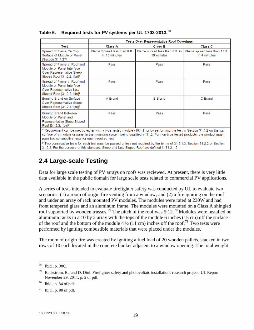
Table 6. Required tests for PV systems per UL 1703-2013.68
2.4 Large-scale Testing
Data for large scale testing of PV arrays on roofs was reciewed. At present, there is very little data available in the public domain for large scale tests related to commercial PV applications.
A series of tests intended to evaluate firefighter safety was conducted by UL to evaluate two scenarios: (1) a room of origin fire venting from a window; and (2) a fire igniting on the roof and under an array of rack mounted PV modules. The modules were rated at 230W and had front tempered glass and an aluminum frame. The modules were mounted on a Class A shingled roof supported by wooden trusses.69 The pitch of the roof was 5:12.70 Modules were installed on aluminum racks in a 10 by 2 array with the tops of the module 6 inches (15 cm) off the surface of the roof and the bottom of the module 4 ½ (11 cm) inches off the roof.71 Two tests were performed by igniting combustible materials that were placed under the modules.
The room of origin fire was created by igniting a fuel load of 20 wooden pallets, stacked in two rows of 10 each located in the concrete bunker adjacent to a window opening. The total weight
68 Ibid., p. 38C. 69 Backstrom, R., and D. Dini. Firefighter safety and photovoltaic installations research project, UL Report,
November 29, 2011, p. 2 of pdf. 70 Ibid., p. 84 of pdf. 71 Ibid., p. 90 of pdf.

1600223.000 - 5873 20
of the pallets was 795 lbs (359 kg).72 The pallets were ignited with a standard ignitor and the flames vented from the window opening. There was a slight wind on the day of the test and and only a slight ignition of the roof occurred.73 The test was terminated after 19 minutes. The test was repeated with the addition of a fan to direct the flames towards the roof. The fan produced a velocity of 500 ft/min (2.5 m/s), but was not able to overcome the ambient wind conditions of 200 ft/min (1 m/s). The test was terminated after 18 minutes.
The first large-scale test with combustible material under the modules was conduted by placing a Class B brand along with 1455 grams (3.2 lbs) of pine straw under modules in the center of the bottom row of the array.74 The fire that was ignited burned for a period of time, but it did not propagate and the test was stopped. A Class A brand was placed under a module near the center of the bottom row of the array and ignited. The fire propagated and flames were visible after 6 minutes. After 21 minutes, the test was terminated and the fire was extinguished. The fire did not cause any structural damage to the roof, but five modules were completely destroyed and one was damaged.75 The resulting fire is shown in Figure 1076 and the damaged roof after the fire was extinguished is shown in Figure 11.
The second large-scale test with combustible material under the modules was conducted by igniting a fuel load consisting of 25 pounds (11 kg) of pine straw placed under six modules near the center of the array.77 The fire propagated and flames were visible after two minutes. After 48 minutes, flames were observed on the underside of the OSB roof deck. The fire is shown in Figure 12. The fire completely consumed nine modules.78
72 Ibid., p. 124 of pdf. 73 Ibid., p. 125 of pdf. 74 Ibid., p. 129 of pdf 75 Ibid., p. 134 of pdf. 76 Ibid., p. 130 of pdf. 77 Ibid., p. 137 of pdf. 78 Ibid., p. 138 of pdf.

1600223.000 - 5873 21
Figure 10. Modules sagging from heat during the first test with fire ignited between the modules and the roof.
Figure 11. Damaged roof after extinguishment of the first test with fire ignited between the modules and the roof.

1600223.000 - 5873 22
Figure 12. Fire from test with pine straw under the PV modules.
2.5 Testing of Mitigation Solutions
Several fire mitigation techniques were tested by UL during the process of revising UL 1703.79,80 The tests involved Class C rated modules mounted on Class A rated steep-slope roof assemblies exposed to the spread of flame test.The roof assembly used was as specified in the UL 1703 spread of flame test. All tests were conducted with standoff heights of 5 inches. The roof and solar module setup was modified with one or more fire mitigation solutions. Success was evaluated based on the ability of the mitigation solution to limit flame spread to less than 6 feet (required for a Class A roof).
2.5.1 Vertical Flashing
Non-combustible vertical flashing was added to the leading edge of the module. The sides and the trailing edge were left open. Tests were conducted with no gap between the roof and the flashing and with a gap of 1 or 2 inches (2.5 or 5 cm). Tests were also conducted with set back distances of 3 inches and 12 inches (7.5 and 30 cm) between the non-combustible flashing and the leading edge of the solar module. The results are reported to be:
79 Sherwood et al. Fire classification rating testing of stand-off mounted photovoltaic modules and systems,
August 2013, p. 9: http://www.solarabcs.org/about/publications/reports/flammability-testing/pdfs/SolarABCs-36-2013-1.pdf
80 Backstrom et. al. Effect of Rack Mounted Photovoltaic Modules on the Fire Classification Rating of Roofing Assemblies - Demonstration of Mitigation Concepts, UL Report, February 10, 2010, p. 23.

1600223.000 - 5873 23
• Vertical flashing installed with gaps (to the roof surface) were not successful. During these tests, flame propagation exceeded the length of the deck (> 8 ft or >2.4 m).
• Vertical continuous (to roof surface) metal flashing mounted to the leading edge of the PV module was successful in blocking flames and preventing ignition of the roof under the module.
• Continuous metal flashing mounted independent of the PV module as a fire block with set back distances of 3 inches and 12 inches (7.5 and 30 cm) were successful. During these tests the back of the PV module and the roof under the module did not ignite.
2.5.2 Fire Barriers
A ¼-inch rigid non-combustible board (6.4 mm) mounted directly to the back of the module limited flame propagation to 0 ft. A commercially available thin fire barrier sheet mounted directly to the back of the module limited flame propagation to 6 ft (1.8 m).
2.5.3 Setback
Testing was conducted with a module setback of 36 inches from the leading edge of the roof. Testing with only this setback as a mitigation technique experienced flame propagation of 8 ft (2.4 m) and was not successful.
2.5.4 Angled Flashing with Setback
Experiments were conducted using combinations of setback distances and angled flashing constructed from ½-inch (12.8 mm) non-combustible board. The flashing was mounted at a 45° angle with a 1-inch (2.5 cm) gap between the flashing and the roof. Angled flashings mounted to the leading edge of the PV module and installed with a 1-inch (2.5 cm) gap (to the roof surface) were not successful at setback distances of 12 and 24 inches (30 and 61 cm). A 36-inch (91 cm) setback was successful with an angled flashing.
2.5.5 Screen
Experiments were conducted to demonstrate the effectiveness of screens to block the entrance of the ignition source flames. Two types of screens were used. One was an expanded metal screen with diagonal openings that measured ½ inch by ¼ inch (12.8 mm by 6.4 mm). The other was an insect screen with 18 openings per inch. Only the insect screen was successful at blocking the entrance of the ignition source flames. Tests using the insect screen and setbacks of 24 and 36 inches (30 and 61 cm) experienced flame propagation > 8 ft (2.4 m) and were not successful.

1600223.000 - 5873 24
3. Gap Analysis
As discussed in the previous section, there has been significant testing directed at understanding the fire behavior of roofing assemblies and PV systems in the context of standardized fire testing. Much of this work has focused on understanding the effects on the fire behavior of roofing assemblies from standoff mounted PV systems. The research described in Section 2.3 demonstrated that the presence of PV modules can negatively impact the fire behavior of a roof. As a result of this testing, UL 1703 was updated in 2013 to evaluate PV modules, mounting hardware, and roofing assemblies as a system. Significant gaps exist in the following areas:
1. Large roof assembly tests. There is limited data available for fire testing of roofing assemblies larger than the ASTM E108 test decks with or without PV modules installed. Testing conducted by UL on roofs with 2 by 10 arrays (described in Section 2.4) demonstrated that fires ignited under modules in the center of the array can propagate within the array and penetrate a combustible roof deck. If additional large scale test data were available it could serve as am important validation of intermediate scale tests such as ASTM E108, UL 1703, and FM Approval 4470.
2. Low slope roof mitigation solutions. There is somewhat limited data available for testing of fire mitigation solutions, and it is focused on steep-slope applications. Testing at UL that was focused on understanding the effect of PV modules on roof behavior in the context of the ASTM E108 tests included an investigation of some fire mitigation solutions. The mitigation solutions that were considered are: vertical flashing, fire barriers on the back of the PV modules, variable setback distances from the edge of the roof, angled flashing with setback, and screens installed at the leading edge of the PV module from the roof surface to the module.
3. Thermal barriers. There has not been any published literature on testing that focused on non-combustible cover boards or other thermal barriers placed on the roof.
4. Effect of walkways. There has not been any published literature on testingthat specifically focuses on determing the effect of walkways as a mitigation solution, although the testing that investigated the effect of module setback indicates that a horizontal gap between the fire source and modules could serve as a mitigation solution.
5. Intumescent paints. There has not been any published literature on testing that focuses on mitigation solutions such as intumescent paints.
1600223.000 - 5873 25
4. General Parameters for Large-Scale Tests
Based on the information that has been reviewed, the following general parameters are proposed for large-scale tests to evaluate solutions to mitigate fire spread.
4.1 Test Array Geometry
The mounting system used for the test array should be typical of solar PV arrays and represent a worst case fire challenge. Initial tests may be required to determine which installation configuration represents a worst case fire challenge. Installation configurations that will be considered will include flat mounted, angled, and east-west tented configurations. It is expected that either flat mounted or east-west tented configurations will provide the greatest fire challenge due to the air channels and radiative feedback that is expected to result from those configurations.
The size of the test array that is selected for the planned tests should satisfy a number of test objectives. The test array should be:
• Large enough to allow a fire to develop that has fire dynamics representative of large roof fire incidents.
• Large enough to allow for the implementation of the proposed mitigation solutions and to evaluate the effectiveness of the mitigation solutions.
• Not so large that it significantly prohibits the number of tests that will be conducted.
A 4 by 5 test array of PV modules is expected to satisfy the aforementioned criteria. Such an array is:
• Larger than the roof sections tested in the ASTM E108 spread of flame test and is therefore expected to have similar fire dynamics to large roof fires. It is expected that a baseline fire ignited in the test array without any mitigation solutions installed would propagate a significant distance through the array. This will allow for the effectiveness of the mitigation solutions to be evaluated.
• Large enough to install the center, leading edge PV module without any fire mitigation features and allow the roof to ignite under that module before spreading into the rest of the array.
• Large enough to allow for the measurement of flame spread to the adjacent rows. The test array is also symmetric, which allows the leading edge center row module to be ignited, and flame spread to the adjacent rows to be observed.
• Large enough to allow for the measurement of forward (wind aided) flame spread during the test over distances that are greater than those measured in the ASTM E108 spread of flame test.
1600223.000 - 5873 26
• Large enough to install mitigation features (such as vertical barriers, non-combustible cover board, or loose gravel) and evaluate their effectiveness at mitigating flame spread over an area that is larger than the ASTM E108 test roof size.
• Large enough to allow an unprotected section of roof under a single module to be ignited, and evaluate the extent of flame spread into areas that are protected with barriers such as non-combustible cover board or gravel.
• Large enough to allow an unprotected section of roof that is longer and wider than the largest test specimen used in the ASTM E108 to be encircled with vertical barriers in order to evaluate the ability of the vertical barriers to limit the extent of flame spread.
• Not so large that flame spread is unpredictable and unrepeatable. There is a large amount of test data available for ASTM E108 spread of flame tests and based on this data it is expected that a fire ignited in the test array will spread across the array, which is slightly larger than an ASTM E108 test roof. An array that is significantly larger may have unpredictable flame spread characteristics.
The target array used should allow for easy adjustment for multiple test conditions and allow for evaluation of whether the fire can propagate across gaps and barriers. Ignition of the target array will be used as a measurable outcome of the tests and used to evaluate the mitigation solutions. A single row of modules should provide an adequate target array due to the fact that ignition of (and not flame spread throughout) the target array will be a measurable test outcome.
It is expected that a 4 by 5 test array with 1 by 5 and 4 by 1 target arrays, as shown in Figure 13, will satisfy the test objectives. If baseline tests indicate that lateral flame spread does not reach the outside edges of the test array, the Project Technical Panel may consider reducing the test array size to a 4 by 3 array. The target arrays will be separated from the test array by a 4-foot wide walkway, which is the minimum aisle width permitted by the International Fire Code and NFPA 1.81 The leading edge of the array will be located at the leading edge of the roof. Previous tests described in Section 2 have shown that a module setback will lead to the roof igniting first and the module igniting second. This is reflected in the 3-foot (0.9 m) minimum setback of the modules in the UL 1703-2012 test. It is the intent of the current test plan to create a more severe fire exposure by igniting the roof and leading PV module at approximately the same time. If the racking system that is used for the array does not permit the modules to be mounted at the roof edge, then the offset will be the minimum permitted by the racking system.
81 International Fire Code 2012, Section 605.11.3.3.3, and NFPA 1 - 2015, Section 11.12.2.2.3.3.2.

1600223.000 - 5873 27
Figure 13. Proposed test array and target array geometry.
Baseline tests will be conducted using commercially available modules installed on racking systems with cables wired using connection boxes and using different module orientations. The orientations considered will be:
• Flat
• East-west tented
• All modules facing in the same direction
Flat module orientations will will be installed using a racking system such that all modules are horizontal and parallel with the roof. Gaps between the modules will be as small as allowed by the racking system used. Modules will be mounted with a standoff height of 5 inches. The standoff height will be measured as an average across the width of the modules. Previous tests using ASTM E108 (described in section 2) have shown a standoff height of 5 inches to be a worst-case scenario. These previous tests used flat module orientaions. It is believed that an average standoff height of 5 inches (13 cm) will also be a worst case scenario for angled module orientations.

1600223.000 - 5873 28
East-west tented orientations will be installed using a racking system with the modules tilted in alternating directions, as shown in Figure 14.82 The gaps between modules will be as small as allowed by the racking system used. Modules will be mounted with a minimum standoff height of 5 inches (13 cm), which was demonstrated in the testing described in Section 2 to be a worst-case scenario. The modules will be angled at 10°, which is a common installation angle due to the optimal economic benefits.83
Figure 14. East-west tented module configuration.
Orientations with all modules facing in one direction will be installed using a racking system that provides a constant tilt angle, as shown in Figure 15.84 The tilt angle will be 10°, which is a common installation angle due to the economic benefits,85 and modules will be installed with a minimum standoff height of 5 inches (13 cm), which was demonstrated by the testing described in Section 2 to be a worst-case scenario.
82 Image from https://www.solarcity.com/sites/default/files/zep-commercial-solutions-sheet-140914.pdf 83 http://us.sunpower.com/sites/sunpower/files/media-library/white-papers/wp-impact-tilt-angle-system-
economics-area-constrained-rooftops.pdf 84 Image from http://blog.solarcity.com/topic/installation. 85 http://us.sunpower.com/sites/sunpower/files/media-library/white-papers/wp-impact-tilt-angle-system-
economics-area-constrained-rooftops.pdf

1600223.000 - 5873 29
Figure 15. Configuration with all modules facing in the same direction.
An initial round of baseline tests will be performed in which tests will be conducted on each of the three module orientations individually. The module orientation that is determined to be a worst-case scenario based on the extent of flame spread will be used for subsequent testing and evaluation of mitigation solutions.
4.2 Ignition Source
The ignition source for the planned tests should be reliable, reproducible, and capable of producing a fire that spreads across a low slope roof with solar PV modules installed.
Possible ignition sources for the tests include combinations of the following:
• Gas burner.
• Class A burning brand.
• Standard ignitors (plastic bag, gauze, and flammable liquid).
• Light combustibles (straw, pine needles wood excelsior, etc.).
The planned testing is intended to evaluate techniques to mitigate flame spread across low-slope roofs with solar arrays. As such, a gas burner similar to the burner used for the ASTM E108 spread of flame test offers several advantages over other possible ignition sources. A gas burner is reliable, repeatable, and has been demonstrated capable of igniting a fire that propagates across a Class A fire rated roof assemblies when PV modules are installed in a standoff configuration. Solid and liquid fuel ignition sources are less reliable, less repeatable, and may require initial testing to calibrate the size of the required ignition source. Solid combustibles such as Class A burning brands are typically used to evaluate the ability of a roof to resist an

1600223.000 - 5873 30
exterior fire penetrating through the roof deck. The ASTM E108 burning brand test is not performed on roofing assemblies that are intended for low-slope applications or roofs that have non-combustible roof decks. For these reasons, solid and liquid fuel igniters are considered to be less appropriate than a gas burner for evaluating flame spread properties of low slope roofs.
A gas burner ignition source similar to that used in the ASTM E108 spread of flame satisfies the test objectives for the planned tests. The gas burner used for the tests will be constructed from 2-inch OD steel pipe. A ½-inch by 48-inch (1.3 by 122 cm) longitudinal slot will be machined into the pipe to serve as the gas outlet. Gas will be fed into this pipe from both sides, similar to the ASTM E108 burner. The burner will be oriented so that flames directly impinge on the roof and the leading modules. The heat output of the burner will be 28,500 BTU/min (505 kW). This will produce a fire exposure with an approximately equivalent heat output per linear foot as the ASTM E108 gas burner.86
4.3 Air Flow
Air flow will be provided to augment the fire propagation across the test roof and simulate wind driven flame spread. ASTM E108 testing has demonstrated that a 12 mph (5.3 ± 0.2 m/s) air velocity can allow a fire to spread across an 8 foot long, Class A fire rated roof with PV modules mounted in a standoff configuration.
Fans with louvers and straightening vanes (if needed) that produce a relatively uniform 12 mph air velocity across the test array satisfy the test objectives for the planned tests. This velocity will be measured using a velocity probe such as a hot wire anemometer or bi-directional probe. Wind speed will be verified prior to tests at the approximate location where the wind enters the array. For reference only, wind speed will be measured under the modules in the array and at the rear of the array prior to the tests.
4.4 Test Instrumentation
Data collection during the tests will include:
• Photodocumentation of: - The construction of the roof assembly.
- The construction of the solar array.
- Test in-progress.
- Post-test condition of the roof assembly and solar array.
• Video recording of the test from multiple viewpoints.
• Water cooled total heat flux gauges located at the target arrays and mounted at the height of the modules and oriented towards the test array.
86 Both the ASTM E108 gas burner (for Class A roof tests) and the proposed gas burner will have an output of
approximately 7,200 BTU/min per linear foot.

1600223.000 - 5873 31
• Thermocouples located under each PV module along the center row.
The overall proposed test geometry, including the test array, target array, ignition source, air supply, and instrumentation is shown in Figure 16.
Figure 16. Overall proposed test geometry.
4.5 Test Procedure
Tests will be conducted using the following general procedure:
1. Turn on fans. Verify air flow velocity at the leading edge of the array. 2. Turn on cameras and data acquisition equipment. 3. Ignite burner. 4. Observe flame propagation. 5. Terminate test after one or more of the following occurs:
a. One or more target array modules ignite and become fully involved. b. Fire propagates across test array, consumes roofing materials, and self-
extinguishes or reduces in size significantly. c. One hour fire exposure does not propagate across test array.
1600223.000 - 5873 32
6. Suppress the fire using hose lines. 7. Document condition of roof assembly and all solar modules.

1600223.000 - 5873 33
5. Roof Assemblies to be Tested
Roof assemblies selected for the planned tests should be representative of roofs on which solar PV arrays are typically installed. A review of common roof assemblies was performed to identify common roofing materials.
The National Roofing Contractors Association (NRCA) routinely performs market surveys of the types of roofing systems that are installed by their members. The results of their 2014 survey87 for low slope installations are broken down by roof system types, roofing insulation material type, and roof deck material type, and are shown in Table 7 through Table 9. The most common roofing systems were thermoplastic olefin (TPO), ethylene propylene diene monomer (EPDM), polymer-modified bitumen, and polyvinyl chloride (PVC), as shown in Table 7.
Table 7. 2014 and projected 2015 low slope roofing sales by roof system type.
The most common insulation type reported in the NRCA market survey was polyisocyanurate (PIR) and the most common roof deck material reported was steel, as shown in Table 8 and Table 9.
87 NRCA Market Survey 2014-2015, National Roofing Contractors Association, Rosemont, IL, 2014.

1600223.000 - 5873 34
Table 8. 2014 and projected 2015 low slope roofing insulation installation by material type.
Table 9. 2014 and projected 2015 low slope roofing deck installation by material type.
Based on these survey results, the following roof assemblies satisfy the test objectives:
• TPO, EPDM, or PVC single ply membranes.
• Polyisocyanurate roof insulation.
• Steel roof deck.
The specific roofing products selected will be such that the roof assembly achieves a Class A fire rating. The thickness of polyisocyanurate roof insulation used will be 4 inches, which is identical to the insulation used in the UL 1703-2013 test.

1600223.000 - 5873 35
6. Mitigation Solutions to be Tested
Three primary mitigation solutions will be evaluated:
• Walkways – Variable width walkways will be added between the test array and target array. Walkways of a minimum critical width may be able to prevent the fire from jumping the walkway gap. This solution is most suited for new installations. Concrete paver blocks (nominally 2 inches thick) will be added to the walkways. Walkways will be 4 feet wide.
• Non-combustible cover board – A non-combustible cover board placed between the combustible insulation and the roof membrane may protect the insulation from the fire exposure and limit flame spread. FM Global has reported some successful initial testing with ¼-inch (6.4 mm) gypsum board. This solution is most suited for new installations.
• Vertical barriers – Vertical barriers placed within the PV array may limit the extent of flame spread. This solution is suited to new installations and some existing installations. Testing described in Section 2 indicates that flashing that was continuous to the roof was successful in mitigating fire propagation.
Additional mitigation solutions that will be considered for evaluation will include:
• Gravel ballast – Gravel is commonly used as ballast for loose-laid, single-ply membrane systems at an areal density of 10 lbs/ft2(49kg/m2). A layer of gravel could be added to roofs that are capable of supporting the extra load. The gravel could provide a thermal barrier to the roof and limit flame spread. Preliminary testing on smaller roof assemblies could be performed to determine the effect of different gravel diameters and lower areal densities. Larger diameters are a more desirable solution because they are less likely to become projectiles and damage PV modules. Lower areal densities are a more desirable solution because they can be implemented on weaker roofs. This solution is suited to new installations and some existing installations.
• Non-combustible module backing layer – A non-combustible board, coating, or fire barrier sheet applied to the back of the PV module may prevent the polymer encapsulant and backing materials from becoming involved in the fire. This solution is suited to both new and existing installations.
• Increased standoff height – A standoff height that is significantly greater than 5” could reduce the severity of a fire by reducing radiative feedback between a burning module and the roof.

1600223.000 - 5873 36
7. Test Matrix
The proposed test matrix is shown in Table 10. Five baseline tests will be conducted to determine the performance of membrane types and module orientation. Three membrane types will be evaluated: EPDM, TPO, and PVC. Additionally, three module orientations will be evaluated: flat slope, all modules angled in one direction, and east-west tented. The first three tests will evaluate the three roof membrane types using a flat module orientation. The membrane type that demonstrates the greatest extent of flame spread will be used for subsequent tests. Tests 4 and 5 will provide baseline data for angled and tented module orientations. Based on the results of these baseline tests, one combination of roof construction and module orientation will be used for the remaining tests to evaluate mitigation solutions.
Table 10. Test matrix.
Test # Membrane Type Orientation Mitigation Solution
1 EPDM Flat None (baseline)
2 TPO Flat None (baseline)
3 PVC Flat None (baseline)
4 Worst case from 1-3 Angled None (baseline)
5 Worst case from 1-3 Tented None (baseline)
6 Worst case from 1-3 Worst case from 1-5 Walkway
7 Worst case from 1-3 Worst case from 1-5 NC cover board
8 Worst case from 1-3 Worst case from 1-5 Vertical barriers
9 Worst case from 1-3 Worst case from 1-5 Possible additional tests
7.1 Baseline Tests
The first five tests will be considered baseline tests and will be conducted without any mitigation solutions installed. The first three tests will evaluate the performance of EPDM, TPO, and PVC membranes. Modules will be in the flat orientation because that is expected to provide the most severe fire conditions. The walkway distance between the test array and target arrays will be zero. The membrane that demonstrates the greatest extent of fire propagation during these tests will be used for all subsequent tests. Extent of fire propagation will be measured by evaluating the damage to the modules and the roof assembly. Test 4 will be performed with all modules angled in the same direction. Test 5 will be performed with modules in a tented configuration. The geometry for the baseline tests is shown in Figure 17.

1600223.000 - 5873 37
Figure 17. Baseline test geometry (Tests 1-5).
7.2 Evaluation Tests
Subsequent tests will be conducted on roofs with one of the mitigation solutions installed. The module orientation will be the orientation from the first five tests that produces the greatest extent of flame propagation.
Test 6 will be performed with paver blocks installed on the 4-foot (1.2 m) walkways between the test array and target array. The geometry for Test 6 is shown in Figure 18 and the areas to be covered with paver blocks are indicated with light orange.

1600223.000 - 5873 38
Figure 18. Geometry for Test 6 (Walkways).
Test 7 will be conducted with a layer of ¼-inch (6.4 mm) non-combustible board between the membrane and the insulation. The non-combustible board will be installed under the membrane and on top of the insulation across the entire test roof assembly. The geometry for Test 7 will be as shown in Figure 17.
Test 8 will be conducted with metal vertical barriers installed within the array. The vertical barriers will extend from the roof surface up to the top of the modules. The test geometry will be as shown in Figure 19.
After the conclusion of Test 8, additional tests may be conducted at the discretion of the technical panel. Additional tests may be conducted using gravel ballast, non-combustible module backing layers, increased standoff height, or they may be be conducted using a variation of one of the previous tests. If mitigation solutions fail a test, it may be determined to be appropriate to conduct additional tests using a modified version of the mitigation solution.

1600223.000 - 5873 39
Figure 19. Geometry for Test 8 (Vertical Barriers)