development of boiler technology for 700°c a-usc … vol 49 o 2 2016 development of boiler...
TRANSCRIPT

34 Vo l . 4 9 N o . 2 2 016
Development of Boiler Technology for 700°C A-USC Plant
KUBUSHIRO Keiji : Doctor of Engineering, Manager, Materials Department, Research Laboratory, Corporate Research & Development NOMURA Kyohei : Doctor of Engineering, Materials Department, Research Laboratory, Corporate Research & Development MATSUOKA Takaaki : Manager, Welding Technology Department, Production Engineering Center, Corporate Research & Development NAKAGAWA Hirokatsu : Manager, Boiler Design Department, Boiler Plant Division, Energy & Plant Operations MUROKI Katsuyuki : Manager, Boiler Plant Planning Department, Boiler Plant Division, Energy & Plant Operations
For the purpose of putting 700°C Advanced-Ultra Super Critical (A-USC) power generation technology into practical use, IHI developed fundamental technologies for boilers from 2008 to 2013. In particular, IHI examined the welding technology and bending technology of Ni-based alloy piping of the candidate materials. In the end, IHI established welding methods for every candidate material, even though the welding conditions are different for each material. Regarding bending technologies including cold bending, IHI also established the optimal machining conditions. Based on these conditions, IHI manufactured mockups of header pipes and loop pipes and verified that construction of an actual machine was possible. 100 000 h creep rupture tests are being conducted on welded parts to verify their long-term durability at high temperatures.
1. Introduction
Recently, there is a great need for enhancing coal-fired power generation in view of the need for reducing greenhouse gases emissions such as carbon dioxide (CO2). Japan has led the world in enhancing the power generation efficiency by increasing steam temperatures. Figure 1 shows the trend in steam conditions in developing coal-fired power generation technologies. A steam temperature of 593°C was achieved in the 1990’s(1) followed by 620°C in 2009 which is the highest temperature used in commercial boilers throughout the world and holds the unbroken record since then.(2) The power generation efficiency of coal-fired power generation has been drastically improved over the last 20 years. However, because its CO2 emissions are higher than the other power generation technologies, coal-fired power generation still needs further enhancement of power generation efficiency and technological development for CO2 recovery. Amidst these circumstances, 700°C Class Advanced Ultra-Super Critical (hereinafter referred to as A-USC) pressure has drawn people’s attention as one means to achieve coal-fired power generation having enhanced power generation efficiency.(3)-(5) This A-USC technology has been adapted to use steam at a temperature of 700°C which is 100°C higher than the current 600°C USC power-generating technology and therefore expected to lead to applications not only in new power plants but also in the renewal or replacement of existing coal-fired power plants. Because of its expected capability to increase the power generation efficiency by 4% or more compared to the current USC technology, it is believed that A-USC technology will
contribute to reducing CO2 emissions by approximately 10%.The development of the A-USC technology was initiated in
Europe in 1998. Currently, it is being actively developed worldwide including in the USA, India, China and Russia.(6)-(9) Europe and the USA in particular have already conducted boiler component tests and lead the world in this field. India and China are in the fundamental technology development stage. Russia has been developing original materials but it is
Ste
am te
mpe
ratu
re (
°C)
Inaugural year of operation (y)
5
0
10
15
20
25
600
550
500
450
400
19551960
19651970
19901995 2005 2015
30
40
50
16.6
24.1
31.0
4.1
450
482485
538
566 593
610 620
(Base)
2000
700
2010 2020
Ste
am p
ress
ure
(M
Pa)
: Steam temperature: Steam pressure: Hekinan boiler No. 3 (24.1 MPa, 538/593°C): Tachibanawan boiler No. 1 (25.0 MPa, 600/610°C): New Isogo boiler No. 1 (26.6 MPa, 600/610°C): New Isogo boiler No. 2 (26.7 MPa, 600/620°C): Target of A-USC boilers
Fig. 1 The trend in the development of steam conditions in Japan

35Vo l . 4 9 N o . 2 2 016
expected to take more time before these materials can be subjected to boiler component tests. In Japan, the “Development of the fundamental technologies for the commercialization of A-USC thermal power” was started in 2008 as a project subsidized by the Agency for Natural Resources and Energy in the Ministry of Economy, Trade and Industry with the participation of domestic material, turbine, valve and boiler manufacturers. IHI has participated in its development as a boiler manufacturer and contributed to developing boiler fundamental technology. Figure 2 shows the development plan for A-USC fundamental technologies. Because A-USC technology applies Ni-base alloys to boiler piping, it is necessary to establish production technologies including for the welding and fabrication of such material. Efforts to establish such production technologies were made from 2008 to 2013. The design as well as fabrication and operation planning for boiler component testing have been conducted since 2014. Since it is also important that the boiler material have long-term reliability under high temperatures, material verification tests for long-term creep rupture strength have been conducted continuously since 2010. Trends in design technologies for A-USC boilers have already been introduced in the previous report.(10)
This report focuses on welding and bending technologies of Ni-base alloys which have been developed as part of the fundamental technologies together with interim results of verification tests on creep rupture strength at weld and bent sections. To develop a welding technology, welding conditions were first tested using test pieces of plates and welding technology then was developed by utilizing an actual scale test model and these were finally verified using a mock-up.
2. Characteristics of the candidate materials of A-USC boilers
This section explains the characteristics of candidate materials for A-USC boilers. First, Fig. 3 shows the 100 000 h creep
rupture strength of several boiler materials together with those used in the USC technologies. In current production of USC power generation, the materials used in high temperature ranges are respectively ferrite steel (Gr. 91 and Gr. 92) for pipes and austenitic stainless steel (SUPER 304H and HR3C) for heat-transfer tubes. The high-temperature strength of these materials is around 100 MPa at a temperature close to 600 to 650°C. The ferrite steel has a tempered martensite structure with precipitation of fine carbide and nitride to increase high-temperature strength and therefore requires adjustment of the precipitation amount by applying thermal treatment prior to usage. Austenitic stainless steel (SUPER 304H, HR3C) is a material subjected to solution heat treatment and delivers high-temperature strength via the
2008 2010 20132009 20122011 2014 20162015
Test production of plate, tubes and pipe using candidate materials and evaluation of basic characteristics
Fabrication of a mock-up
Tec
hnol
ogy
Rea
dine
ss L
evel
(T
RL
)
Verification of plant construction and operation with a boiler component test
2017
Establishment of production technology for pipe and tube materials
Verification of 100 000 h creep rupture strength for weld sections
2013
2014 - 2017
2008 - 2009
2010 - 2012
Year
Fig. 2 The development plan of A-USC technology
100
000
h cr
eep
rupt
ure
stre
ngth
(M
Pa)
550 600 650 700 750 800 850
Temperature (°C)
400
300
200
100908070
60
50
40
30
: Alloy740: Alloy263: Alloy617: HR35: HR6W
: HR3C: SUPER304H: Gr.92: Gr.91
Fig. 3 100 000 h creep rupture strength of boiler materials
36 Vo l . 4 9 N o . 2 2 016
precipitation of fine carbide and nitride during use. In other words, this material changes its structure while being used and provides strength at high-temperatures.
In contrast, Ni-base alloys (Alloy740, Alloy263, Alloy617, HR35 and HR6W), which are candidate materials for A-USC boilers, have a 100 000 h rupture strength of 100 MPa at temperatures in the vicinity of 650 to 750°C. Thus, Ni-base alloys allow increasing the temperature of boiler materials by 100°C compared to ferrite and austenite stainless steel. These Ni-base alloys achieve high-temperature strength by utilizing intermetallic compound phases for phase strengthening or toughening. The high-temperature strength of the Ni-base alloys increases as the volume percent of their intermetallic compounds are increased. In general, most intermetallic compounds quickly precipitate during thermal treatment to significantly increase the room-temperature strength of the Ni-base alloys. Intermetallic compounds are therefore thought likely to degrade the weldability and workability of the Ni-base alloys. As just described, the candidate materials for A-USC boilers are different from the materials used for current USC not only in terms of strength but also strength development mechanisms and thereby require a full understanding of their characteristics when used. The following sections therefore address results from evaluating the weldability and workability of the candidate materials, HR6W,(11) HR35,(12) Alloy617, Alloy263 and Alloy740H.(13)
3. Establishment of welding technology
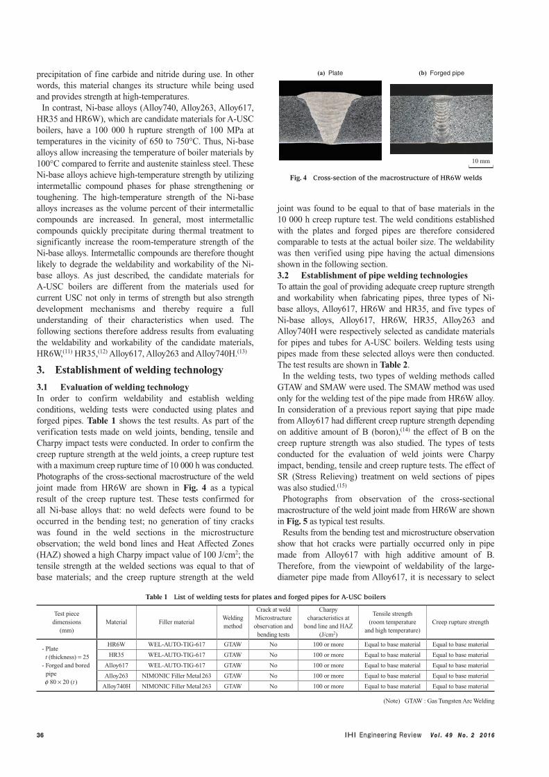
3.1 Evaluation of welding technologyIn order to confirm weldability and establish welding conditions, welding tests were conducted using plates and forged pipes. Table 1 shows the test results. As part of the verification tests made on weld joints, bending, tensile and Charpy impact tests were conducted. In order to confirm the creep rupture strength at the weld joints, a creep rupture test with a maximum creep rupture time of 10 000 h was conducted. Photographs of the cross-sectional macrostructure of the weld joint made from HR6W are shown in Fig. 4 as a typical result of the creep rupture test. These tests confirmed for all Ni-base alloys that: no weld defects were found to be occurred in the bending test; no generation of tiny cracks was found in the weld sections in the microstructure observation; the weld bond lines and Heat Affected Zones (HAZ) showed a high Charpy impact value of 100 J/cm2; the tensile strength at the welded sections was equal to that of base materials; and the creep rupture strength at the weld
joint was found to be equal to that of base materials in the 10 000 h creep rupture test. The weld conditions established with the plates and forged pipes are therefore considered comparable to tests at the actual boiler size. The weldability was then verified using pipe having the actual dimensions shown in the following section.3.2 Establishment of pipe welding technologiesTo attain the goal of providing adequate creep rupture strength and workability when fabricating pipes, three types of Ni-base alloys, Alloy617, HR6W and HR35, and five types of Ni-base alloys, Alloy617, HR6W, HR35, Alloy263 and Alloy740H were respectively selected as candidate materials for pipes and tubes for A-USC boilers. Welding tests using pipes made from these selected alloys were then conducted. The test results are shown in Table 2.
In the welding tests, two types of welding methods called GTAW and SMAW were used. The SMAW method was used only for the welding test of the pipe made from HR6W alloy. In consideration of a previous report saying that pipe made from Alloy617 had different creep rupture strength depending on additive amount of B (boron),(14) the effect of B on the creep rupture strength was also studied. The types of tests conducted for the evaluation of weld joints were Charpy impact, bending, tensile and creep rupture tests. The effect of SR (Stress Relieving) treatment on weld sections of pipes was also studied.(15)
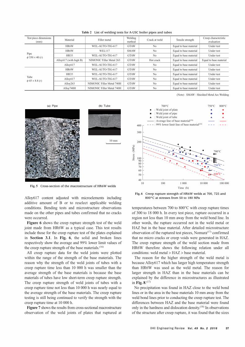
Photographs from observation of the cross-sectional macrostructure of the weld joint made from HR6W are shown in Fig. 5 as typical test results.
Results from the bending test and microstructure observation show that hot cracks were partially occurred only in pipe made from Alloy617 with high additive amount of B. Therefore, from the viewpoint of weldability of the large-diameter pipe made from Alloy617, it is necessary to select
Table 1 List of welding tests for plates and forged pipes for A-USC boilers
Test piece dimensions
(mm)Material Filler material
Welding method
Crack at weldMicrostructure observation and
bending tests
Charpy characteristics at
bond line and HAZ(J/cm2)
Tensile strength(room temperature
and high temperature)Creep rupture strength
- Plate t (thickness) = 25- Forged and bored pipe f 80 × 20 (t )
HR6W WEL-AUTO-TIG-617 GTAW No 100 or more Equal to base material Equal to base material
HR35 WEL-AUTO-TIG-617 GTAW No 100 or more Equal to base material Equal to base material
Alloy617 WEL-AUTO-TIG-617 GTAW No 100 or more Equal to base material Equal to base material
Alloy263 NIMONIC Filler Metal 263 GTAW No 100 or more Equal to base material Equal to base material
Alloy740H NIMONIC Filler Metal 263 GTAW No 100 or more Equal to base material Equal to base material
(Note) GTAW : Gas Tungsten Arc Welding
10 mm
(a) Plate (b) Forged pipe
Fig. 4 Cross-section of the macrostructure of HR6W welds
37Vo l . 4 9 N o . 2 2 016
Alloy617 content adjusted with microelements including additive amount of B or to reselect applicable welding conditions. Bending tests and microstructure observations made on the other pipes and tubes confirmed that no cracks were occurred.
Figure 6 shows the creep rupture strength test of the weld joint made from HR6W as a typical case. This test results include those for the creep rupture test of the plates explained in Section 3.1. In Fig. 6, the solid and broken lines respectively show the average and 99% lower limit values of the creep rupture strength of the base materials.(16)
All creep rupture data for the weld joints were plotted within the range of the strength of the base materials. The reason why the strength of the weld joints of tubes with a creep rupture time less than 10 000 h was smaller than the average strength of the base materials is because the base materials of tubes have low short-term creep rupture strength. The creep rupture strength of weld joints of tubes with a creep rupture time not less than 10 000 h was nearly equal to the average strength of the base materials. The creep rupture testing is still being continued to verify the strength with the creep rupture time at 10 000 h.
Figure 7 shows the results from cross-sectional macrostructure observation of the weld joints of plates that ruptured at
temperatures between 700 to 800°C with creep rupture times of 300 to 18 000 h. In every test piece, rupture occurred in a region not less than 10 mm away from the weld bond line. In other words, the rupture occurred not in the weld metal or HAZ but in the base material. After detailed microstructure observation of the ruptured test pieces, Nomura(17) confirmed that no micro cracks or creep voids were generated in HAZ. The creep rupture strength of the weld section made from HR6W therefore shows the following relation under all conditions: weld metal > HAZ > base material.
The reason for the higher strength of the weld metal is because Alloy617 which has larger high temperature strength than HR6W was used as the weld metal. The reason for larger strength in HAZ than in the base materials can be explained by the difference in microstructures as illustrated in Fig. 8.(17)
No precipitation was found in HAZ close to the weld bond lines or in the area in the base materials 10 mm away from the weld bond lines prior to conducting the creep rupture test. The differences between HAZ and the base material were found only in the hardness and dislocation density.(18) In observations of the structure after creep rupture, it was found that the sizes
10 mm
(a) Pipe (b) Tube
Fig. 5 Cross-section of the macrostructure of HR6W welds
Str
ess
(M
Pa)
10 100 1 000 10 000 100 000
Time (h)
400
300
200
10090807060
50
40
700°C
750°C
800°C
: Weld joint of plate : Weld joint of pipe: Weld joint of tube : Average line of base material(16)
: 99% lower limit line of base material(16)
700°C 750°C 800°C
Fig. 6 Creep rupture strength of HR6W welds at 700, 725 and 800°C at stresses from 50 to 180 MPa
Table 2 List of welding tests for A-USC boiler pipes and tubes
Test piece dimensions(mm)
Material Filler metalWelding method
Crack at weld Tensile strengthCreep characteristic
evaluation
Pipef 350 × 40 (t )
HR6W WEL-AUTO-TIG-617 GTAW No Equal to base material Under test
HR6W WEL117 SMAW No Equal to base material Under test
HR35 WEL-AUTO-TIG-617 GTAW No Equal to base material Under test
Alloy617 (with high B) NIMONIC Filler Metal 263 GTAW Hot crack Equal to base material Equal to base material
Alloy617 WEL-AUTO-TIG-617 GTAW No Equal to base material Under test
Tubef 45 × 8.8 (t )
HR6W WEL-AUTO-TIG-617 GTAW No Equal to base material Under test
HR35 WEL-AUTO-TIG-617 GTAW No Equal to base material Under test
Alloy617 WEL-AUTO-TIG-617 GTAW No Equal to base material Under test
Alloy263 NIMONIC Filler Metal 740H GTAW No Equal to base material Under test
Alloy740H NIMONIC Filler Metal 740H GTAW No Equal to base material Under test
(Note) SMAW : Shielded Metal Arc Welding

38 Vo l . 4 9 N o . 2 2 016
of the Laves phases which increase the creep rupture strength of HR6W, were constant in the crystal grains and grain boundaries regardless of the distance from the weld bond lines. In contrast, tiny precipitation of M23C6 carbide which is another strengthening phase in HR6W was found more in the crystal grains and grain boundaries in HAZ than in the base materials. In terms of precipitation of M23C6 carbide within the crystal grains, the sizes were almost equal in regions about 10 mm away from the weld bond lines but became tinier as distances from the weld bond lines became shorter. In HAZ, the precipitation of M23C6 carbide was larger in the crystal grain boundaries than in regions not less than 10 mm away from the weld bond lines. This demonstrates that HAZ and the base materials have different precipitation distribution
patterns and also that differences in precipitation of M23C6 carbide in the crystal grains and grain boundaries will appear as a difference in the creep rupture strength between HAZ and the base materials. Therefore, unlike ferrite steel, the creep rupture strength of HR6W will not drop in the weld section(19) and creep rupture will not occur in HAZ.(20)-(23)
4. Establishment of the technology for bending techniques
The fabrication of boilers involves a large number of bending techniques. Either hot bending or cold bending is selected for tubes depending on their degree of bending and hot bending by high-frequency induction heating is selected for pipes. Candidate materials selected for the tubes were HR6W, HR35, Alloy617, Alloy263, and Alloy740H and their hot and cold bending properties were verified. The property of hot bending by high-frequency induction heating was verified on HR6W, Alloy617 and HR35 which are candidate materials for the pipes.
Material sections exposed to heat due to heat and high-frequency bending generally undergo a drop in creep rupture strength. These materials are therefore subjected to a thermal treatment to restore the creep rupture strength after bending process. In contrast, material sections subjected to cold bending to a degree of processing which does not cause a reduction in creep rupture strength can be used without any additional treatment. So it is necessary to verify the creep rupture strength in material sections subjected to hot or high-frequency bending and carried out subsequent thermal treatment. In materials subjected to cold bending, it is also necessary to clarify the relation between the degree of processing and the creep rupture strength. In alloys subjected to high-frequency bending, the creep rupture strength on
(g) 800°C, 120 MPa (h) 800°C, 90 MPa (i) 800°C, 80 MPa
(d) 750°C, 140 MPa (e) 750°C, 120 MPa (f) 750°C, 100 MPa
(a) 700°C, 180 MPa (b) 700°C, 160 MPa (c) 700°C, 140 MPa
Weld metal Base material Weld metal Base material Weld metal Base material
Weld metal Base material Weld metal Base material Weld metal Base material
Weld metal Base material Weld metal Base material Weld metal Base material
5 mm
Fig. 7 Cross-sections of the macrostructure of ruptured specimens in HR6W welds
HAZ
After creep rupture test
Before creep rupture test
Item Base material
Laves phases
Carbide
Fig. 8 Schematic illustrations showing the precipitates of HR6W welds before and after creep

39Vo l . 4 9 N o . 2 2 016
heat-treated alloy after high-frequency bending was evaluated; and in tubes, the creep rupture strength was evaluated after cold bending.4.1 Bending testFigure 9 shows pictures of bent pipes made from HR6W. The bending test results for tubes and pipes are shown in Table 3. These pictures show typical bend conditions for HR6W. Conventional manufacturing machines were verified as usable for hot and cold bending of tubes made from all type of alloys. Dimensional measurements and cross-sectional observations confirmed that the ellipticity, flatness and thickness of the test pieces after bend processing were within allowable ranges. The high-frequency bending test made on pipes with currently available facilities confirmed that the ellipticity and flatness after bend processing were within the allowable ranges. Results confirmed that pipes can be manufactured without problems regardless of their size and thickness.
4.2 Creep rupture strength of pipe made from HR6W after bending process
Figure 10 shows the creep rupture strength of HR6W test pieces subjected to solution treatment after high-frequency bending. As shown in Fig. 10, the creep rupture strength of HR6W after high-frequency bending remained in the range between the average strength and 99% lower limit strength of HR6W. A 100 000 h verification test is currently underway. The reason why the thermal treatment enabled the creep rupture strength after bending to remain close to the average strength of the base materials was because all of the carbide precipitated during the bend processing was turned into solution through thermal treatment after bending as shown in Fig. 11. In other words, the creep rupture strength was restored due to the dispersion of coarse precipitate, which acts to reduce creep rupture strength during the thermal treatment
Str
ess
(M
Pa)
20 21 22 2423 25 26
LMP*1/1 000 (C*2 = 18.73)
300
200
100908070
60
50
40
(Notes) *1 : Larson-Miller parameter value *2 : Larson-Miller parameter constant
: HR6W with solution treatment after high-frequency bending (1 220°C × 1 h): Average of base material(16)
: 99% lower limit of base material(16)
Fig. 10 Creep rupture strength of an HR6W bent pipe following the solution heat treatment
(a) Hot bending tube (b) Cold bending tube
(c) Hot bending pipe by high-frequency induction heating
Fig. 9 Appearance of an HR6W bent pipe and tubes
Table 3 List of bending tests for A-USC boiler pipes and tubes
Test piece dimension(mm)
Material Bending methodBending angle
(degree)Bending radius
(DR)Bending
performanceEvaluation of creep rupture strength
Tubef 45 × 8.8 (t )
HR6W
Hot bending
180 1.7 Good —
HR35 180 1.7 Good —
Alloy617 (with high B) 180 1.7 Good —
Alloy263 180 1.7 Good —
HR6W
Cold bending
180 2.8 GoodImprovement of creep strength
through cold working
HR35 180 2.8 GoodImprovement of creep strength
through cold working
Alloy617 (with high B) 180 2.8 GoodImprovement of creep strength
through cold working
Alloy263 180 2.8 Good No effect from cold working
Alloy740H — — —Reduction in creep strength with
creep of 7.5% or more
Pipef 350 × 40 (t )
HR35
Hot bending by high-frequency
induction heating
90 4 Good Same as base material
Pipef 510 × 40 (t )
HR6W 60 3 Good Under test
Pipef 350 × 40 (t )
HR6W 30 4 Good Under test
Pipef 350 × 72 (t )
Alloy617 30 4 Good Under test

40 Vo l . 4 9 N o . 2 2 016
and also due to the new precipitation of fine carbide which increases the creep rupture strength during creep.4.3 Effect of cold working on creep rupture strengthNext, the relation between pre-strain and creep rupture strength was investigated to clarify the effect of cold working on the creep rupture strength. Figure 12 shows the relation between the pre-strain and creep rupture strength.(24) In Fig. 12, life ratios relative to the creep rupture time without pre-strain and pre-strain amounts are respectively plotted on the vertical and horizontal axes. The effects of pre-strain on the creep rupture strength varied largely depending on the type of alloys with HR6W, HR35 and Alloy617 showing increases in creep rupture strength along with an increase in the pre-strain. Alloy263 showed constant creep rupture strength regardless of the pre-strain. In contrast, Alloy740/740H showed constant creep rupture strength up to a pre-strain of 5% and a reduction in creep rupture strength to about one-third that of the creep rupture strength without pre-strain when the pre-strain was at least 7.5%. The effects of cold working on the creep rupture strength vary because of differences in microstructures of the materials.
As reported by Okada,(25) the creep rupture strength of
HR6W was increased due to the increased precipitation of fine Cr carbide in grains as the cold work increased. The same mechanism for the increase in creep rupture strength is also assumed for the alloy HR35. The differences in the effects of the cold working on the creep rupture strength among Alloy617, Alloy263 and Alloy740/740H are considered attributable to differences in their microstructures near the grain boundaries. Figure 13 shows schematic illustrations of the different precipitation patterns in the grain boundaries of several types of alloys. In the case of Alloy617, cold working caused an increase in the precipitation of Mo and Cr carbide in the grain boundary. Creep rupture strength is generally thought to increase along with an increase in precipitation in the grain boundary. The increase in the creep rupture strength was therefore attributable to the increase in the amount of carbide stemming from the increased cold work. In the case of Alloy263, the amount of carbide in the grain boundary was constant regardless of the cold work and therefore the creep rupture strength was also constant. In the case of Alloy740, the amount of carbide in the grain boundary significantly decreased when the cold work was 7.5% or more. The decrease in carbide in the grain boundary was therefore considered the reason for the decline in creep rupture strength.(26)
Evaluation tests for creep rupture strength are currently underway for Alloy617 and Alloy263 with a degree of processing up to 30%.(27), (28) The Alloy263 test piece with cold working showed a slightly higher creep rupture strength than the test piece without cold working. This is because of the fine precipitation of g ’, the intra-granular precipitation, due to the dislocation introduced through the cold working. In the future, the reduction in creep rupture strength over an extended time period will be evaluated by way of a long-term
Lif
e ra
tio
(–)
0 5 10 15 20
Pre-strain (%)
10.0
1.0
0.1
(Note) Temperature : 750°C
: HR6W (Interrupted): HR35: Alloy617: Alloy263: Alloy740/740H
Fig. 12 The effect of cold work on the creep rupture strength of A-USC boiler tubes
(a) After bending (b) Solution treatment after bending
50 µm
Fig. 11 SEI image of HR6W
Without pre-strain
Alloy263
Alloy740H
Alloy617
Material type After cold working
Fig. 13 Schematic illustrations showing the precipitates of cold worked Ni alloys after creep

41Vo l . 4 9 N o . 2 2 016
creep rupture test.
5. Mock-up test
The previous sections addressed the establishment of welding and bending technologies and the verification of the creep rupture strength after bending process. This section focuses on the mock-up test executed to confirm the effectiveness of the established technologies for members expected to be utilized in the actual boiler fabrication. The mock-up comprised looped pipes, a main steam pipe header and a reheater pipe header. Tables 4 and 5 show the specifications, welding methods and bending conditions for materials used in the mock-up. Also, Fig. 14 shows the pictures taken in fabricating the mock-up. The material used for the mock-up was HR6W which is one of the candidate materials. Figure 15 shows pictures of completed parts of the mock-up. Results from the nondestructive inspection showed that no defects were found in the bent and welded sections. Figure 16 shows cross-sectional macrostructure observations of pipe weld sections. These observations confirmed that welding can be safely executed on the main steam pipe header with a pipe diameter up to 138 mm.
6. Conclusion
Technologies for bending and welding of tubes and pipes made from Ni-base alloys serving as candidate piping materials were established in preparation for developing A-USC boilers.
Welding methods utilizing GTAW and SMAW as well as bending method using high-frequency heating were established for candidate materials in pipes. The effect on weldability from the B (boron) content which is a minor component in materials was also clarified using Alloy617. All candidate Ni-base alloys were verified for their creep rupture strength and creep rupture testing has been underway to verify the 100 000 h creep rupture strength.
In contrast, welding method using GTAW and the bending methods using cold and hot bending were established for
candidate materials in tubes. These candidate materials were tested for their creep rupture strength after cold working and the effects of the cold working on the respective candidate materials were clarified.
Based on these established welding and bending technologies,
(a) Welding of a seat for a temperature sensor
(b) Welding of stub pipes
Fig. 14 Preparing for the mock up trial
Table 4 The mock up materials and welding method used for SH and RH header
MaterialPipe(mm)
Filler metalWelding method
Tube(mm)
HR6W f 558 × 138 (t ) WEL-AUTO-TIG-617 GTAW f 50.8 × 11.5 (t )
HR6W f 635 × 72 (t ) WEL-AUTO-TIG-617 GTAW f 63.5 × 11.5 (t )
(Note) SH : Superheat RH : Reheat
Table 5 The mock up materials and bending conditions used for SH and RH header and loop
Material Mock-upDimensions
(mm)Bending method
Bending angle (degree)
Bending radius(DR)
HR6W LoopTube f 50.8 × 11.5 (t )
Hot bending 180 1.7, 2.4, 2.9
HR6W Main steam pipe headerTube f 50.8 × 11.5 (t )
Cold bending 30, 60, 80, 90, 100 2.5
HR6W Hot reheat pipe headerTube f 63.5 × 11.5 (t )
Cold bending 30, 60, 80, 90, 100 2.4
(Note) SH : Superheat RH : Reheat
(a) Main steam pipe header
(c) Looped pipes
(b) Hot reheat pipe header
Fig. 15 Appearance of the mockups

42 Vo l . 4 9 N o . 2 2 016
the boiler component test was started at Mikawa Power Plant (in Fukuoka Prefecture) on April 29, 2015. The test has been executed at a steam temperature of 700°C and sample tests after extubation are expected to be implemented in 2016.
REFERENCES
(1) H. Umaki, I. Kajigaya, T. Kunihiro, T. Totsuka, M. Nakashiro and R. Kume : Application of Large Diameter Seam Welded Pipes and Header of Super 9Cr Steel for 700 MW Coal-Fired Boiler with 593°C Reheat Steam Temperature Ishikawajima-Harima Engineering Review Vol. 31 No. 5 (1991. 9) pp. 339-345
(2) K. Makino : Importance of the Coal Fired Power in Electric Power Energy The thermal and nuclear power Vol. 65 No. 10 (2014. 10) pp. 713-721
(3) K. Nicol : Status of advanced ultra-supercritical pulverised coal technology IEA CCC/229, ISBN978-92-9029-459-5 (2013. 12)
(4) M. Fukuda et al. : Advanced USC The thermal and nuclear power Vol. 62 No. 10 (2011. 10) pp. 731-741
(5) M. Fukuda, E. Saito, H. Semba, J. Iwasaki, S. Izumi, S. Takano, T. Takahashi and T. Sumiyoshi : Advanced USC technology development in Japan Proceeding the 7th International Conference on Advances in Materials Technology for Fossil Power Plants (2013. 10) pp. 24-40
(6) J. Shingledecker, R. Purgert and P. Rawls : Current status of the U.S. DOE/OCDO A-USC materials technology research and development program. Proceeding the 7th International Conference on Advances in Materials Technology for Fossil Power Plants (2013. 10) pp. 41-52
(7) A. Mathur, O. P Bhutani, T. Jayakumar, D. K. Dubey and S. C. Chetal : India’s national A-USC mission – plan and progress Proceeding the 7th International Conference on Advances in Materials Technology for Fossil Power Plants (2013. 10) pp. 53-59
(8) R. Sun, Z. Cui and Y. Tao : Progress of china 700°C USC development program Proceeding the 7th International Conference on Advances in Materials Technology for Fossil Power Plants (2013. 10) pp. 1-8
(9) V. Skorobogatykh. Martensitic and Austenitic steels for Application in A-USC Thermal Power Plants. 2nd AUSC Workshop (2014. 10) presentation only
(10) S. Takano, Y. Aoki, K. Kubushiro, N. Tomiyama and H. Nakagawa : Development of 700 Degree Celsius Class Advanced Ultra-Supercritical Boiler Journal of IHI Technologies Vol. 49 No. 4 (2010. 2) pp. 185-191
(11) H. Semba, H. Okada, T. Hamaguchi, S. Ishikawa and M. Yoshizawa : Development of Boiler Tubes and Pipes for Advanced USC Power Plants Nippon Steel & Sumitomo Metal Technical Report Vol. 397 (2013. 11) pp. 71-77
(12) H. Semba, H. Okada, M. Igarashi, H. Hirata and M. Yoshizawa : Development of Fe-Ni and Ni-base alloys without g’ strengthening for Advanced USC boilers Proceeding of 9th Liege Conference on Materials for Advanced Power Engineering (2010. 9) pp. 360-369
(13) B. A. Baker and R. D. Gollihue : Optimization of INCONEL®740 for Advanced Ultra Supercritical Boilers Proceeding the sixth International Conference on Advances in Materials Technology for Fossil Power Plants (2010. 3) pp. 96-109
(14) D. Tytko, P. Choi, J. Klöwer, A. Kostka, G. Inden and D. Raabe : Microstructural evolution of a Ni-based superalloy (617B) at 700°C studied by electron microscopy and atom probe tomography Acta Materialia 60 (2012. 2) pp. 1 731-1 740
(15) K. Kubushiro, K. Nomura, K. Tokuda and H. Nakagawa : Effect of Stress-Relief Treatments on Microstructure and Mechanical Properties in Weld Joints of 23Cr-45Ni-6W alloy (HR6W) Proceeding 3rd International ECCC Conference (2014. 5)
(16) Japan Power Engineering and Inspection Corporation : Regulatory Study for Advanced Thermal Power Plants 22(2010) Annual Report (2011. 2)
(17) K. Nomura, K. Kubushiro, H. Nakagawa and Y. Murata : Creep Rupture Strength for Weld Joint of 23Cr-45Ni-7W Alloy Journal of Japan Institute Metals and Materials Vol. 79 No. 7 (2015. 7) pp. 348-355
(18) K. Nomura, K. Kubushiro, H. Nakagawa and Y. Murata : Strain Analysis of Weld Joint for 23Cr-45Ni-7W Alloy by XRD and EBSD Method The 170th ISIJ Meeting (2015. 9) p. 912
(19) K. Kimura, M. Tabuchi, Y. Takahashi, K. Yoshida and K. Yagi : Long-term Creep Strength and Strength Reduction Factor for Welded joints of ASME Grades 91, 92 and 122 Type Steels Proceeding of the IIW International Conference (2008. 7) pp. 51-58
(20) S. J. Brett, D. J. Oates and C. Johnston : In-Service Type IV Cracking in a Modified 9Cr (Grade91) Header Proceeding of ECCC Creep Conference (2005. 9) pp. 563-572
(21) A. Shibli : Performance of Modern High Strength Steels (P91, P92) in High Temperature Plant Proceedings of CREEP8 (2007. 7) CREEP2007-26058
(22) K. Yoshida : Regulatory Review Results on Allowable Tensile Stress Values of Creep Strength Enhanced Ferritic Steels Proceedings of CREEP8 (2007. 7) CREEP 2007-26512
(23) J. Parker and S. Brett : Creep performance of a grade
20 mm
(a) Main steam pipe header (b) Hot reheat pipe header
Fig. 16 Cross-section of the macrostructure of HR6W circumferential welds

43Vo l . 4 9 N o . 2 2 016
91 header International Journal of Pressure Vessels and Piping (2013. 11-12) pp. 82-88
(24) K. Kubushiro, K. Nomura and H. Nakagawa : Effect of Cold Work on Creep Strength of Nickel-Base Alloys Proceedings of the “10th Conference on Materials for Advanced Power Engineering” (2014. 9)
(25) H. Okada, H. Semba, S. Ishikawa and M. Yoshizawa : Effect of Cold Working on Creep Property of a 23Cr-45Ni-7W Alloy The 163rd ISIJ Meeting (2012. 3) p. 405
(26) K. Kubushiro, K. Nomura, S. Takahashi, M. Takahashi
and H. Nakagawa : Effect of Pre-strain on Creep properties of Alloy740 Proceeding the sixth International Conference on Advances in Materials Technology for Fossil Power Plants (2010. 8) pp. 164-170
(27) N. Kanno, K. Kubushiro, K. Nomura and H. Nakagawa : Creep behavior of cold worked Alloy263 The 169th ISIJ Meeting (2015. 3) p. 259
(28) N. Kanno, K. Kubushiro and K. Nomura : Microstructure transformation of pre-strained Alloy263 during creep The 170th ISIJ Meeting (2015. 9) p. 908