development of an orbital sounding rocket programpha.jhu.edu/~stephan/asrat/asratppprfifinal.pdf ·...
TRANSCRIPT

ASRAT PPP-RFI Astro2010 1 April 2009
i
1)
2) 3)
Development of an Orbital Sounding Rocket Program
Submitted in Response to the Request for Information from the Astronomy and Astrophysics Decadal Survey Program Prioritization Panels
An activity initiated by the
NASA Astrophysics Sounding Rocket Assessment Team (ASRAT)1
Christopher Martin2 (California Institute of Technology, Chair), Supriya Chakrabarti (Boston University), Ray Cruddace (Naval Research Laboratory), Don Figer (Rochester Institute of Technology), Orlando Figueroa (Goddard Space Flight Center), Walt Harris (University of
California, Davis), Vernon Jones (NASA, Ex Officio), Stephan McCandliss3 (Johns Hopkins University), Ken Nordsieck (University of Wisconsin, Madison), Ron Polidan (Northrup Grumman), Wilton Sanders (NASA HQ, Ex Officio) & Erik Wilkinson (Ball Aerospace)
supported by the Sounding Rocket Project Office (SRPO, code 810)
Philip J. Eberspeaker the
Applied Engineering and Technology Directorate (AETD, code 500) Joel M. Simpson
and the NASA Sounding Rocket Operations Contractor (NSROC)
Northrop Grumman with Special Science Contributions from
Enectali Figueroa-Feliciano (MIT), Randall McEntaffer (Unveristy of Iowa) & Michael Kowalski (NRL)
Abstract– Astrophysics sounding rocket experiments strive to open unique science thrusts by exploiting cutting edge technologies. In the process they produce an irreplaceable source of technically literate leaders for the space astronomy enterprise. Over the years, efforts by these entrepreneurial experimenters to improve the sophistication and capability of their payloads have outpaced the performance envelope of sub-orbital delivery systems, resulting in unrealized scientific potential. This is about to change. Recent competition within the commercial orbital transportation sector has spurred the high volume production of low cost orbital delivery systems that emphasize reliability. The transportation technology is at hand to realize the full science potential of sounding rocket payloads and vet the advanced technologies in an orbital environment, thus honing more closely to the sounding rocket axiom of test-as-you-fly, fly-as-you-test. Here we present potential science programs and a technological approach to initiate a highly competitive and sustainable Orbital Sounding Rocket (OSR) program, whose purpose is to launch science payloads (up to 420 kg) into low Earth orbit frequently (1/yr) at low cost, with a mission duration of up to 30 days. Payload selection would be based on meritorious high-value science that can be performed by migrating sub-orbital payloads to orbit. Establishment of this capability is a tactical essential for NASA as it strives to advance technical readiness and lower costs for risk averse Explorers and flagship missions in its pursuit of a balanced and sustainable program and achieve big science goals within a limited fiscal environment.
Full disclosure statement – Two members of the ASRAT, Webster Cash and Dan McCammon, did not participate in the preparation of this request for information because they sit on Astro2010 SOP panels. Spokesperson: [email protected], California Institute of Technology, 92215, (626) 826-7866. Contact author: [email protected], JHU, 3400 North Charles St, Baltimore, MD 21218, (410) 516-5272.
ASRAT PPP-RFI Astro2010 1 April 2009
Table of Contents Table of Contents............................................................................................................................ ii 1. Executive Summary ................................................................................................................. 1 2. Orbital Sounding Rocket Candidates....................................................................................... 2 2.1. IGM Emission Mapping with UV Integral Field Spectroscopy: Martin PI, Caltech............ 2 2.2. Project Lyman at Low Redshift (0.02 < z < 0.4): McCandliss PI, JHU ............................... 4 2.3. Galactic Hot ISM Studies with Micro-X: Figueroa-Feliciano PI, MIT................................ 6 2.4. Understanding the Soft X-ray Background: McEntaffer PI, UIowa..................................... 8 2.5. Direct Imaging of Extrasolar Planets: Chakrabarti PI, BU............................................... 10 3. Design Principles and Technology Drivers for OSR............................................................. 12 3.1. Launch Vehicle ................................................................................................................... 13 3.2. Payload Support Development ........................................................................................... 13 3.2.1. Attitude control ................................................................................................................ 14 3.2.2. Command and Data Handling (C&DH) .......................................................................... 15 3.2.3. Electrical Power ............................................................................................................... 15 4. Organization of OSR at the Wallops Flight Facility.............................................................. 17 5. Activity Schedule................................................................................................................... 17 6. Cost Estimates........................................................................................................................ 18 This document contains references with active links. View in MS-Word to access them.
ii
ASRAT PPP-RFI Astro2010 1 April 2009
1. Executive Summary The Astrophysics Sounding Rocket program has had, and will continue to have, a profound impact on the success of the nation’s space science program. It provides fresh and timely scientific seeds, critical technology development, and irreplaceable recruitment and training of future mission leaders. However, because of downsizing over the last two decades, NASA is in danger of losing this core capability. As we discussed in the Astro2010 State of the Profession White Paper, Reinvigorating the Astrophysics Sounding Rocket Program: Strategic Investment in the Future of Space Astronomy, a rededication to this program will pay off dramatically in the scope, cost-effectiveness, and scientific discovery potential of NASA’s future medium and large missions. A key component of this revitalization is the initiation of an Orbital Sounding Rocket Program, analogous to the highly successful Long Duration Balloon Program. Orbital Sounding Rockets, built on the infrastructure of proven sounding rocket payloads and development approaches, will fill the yawning gap between 5 minute suborbital flights and >$100M Explorer missions with a new class of scientifically compelling, low-cost missions. Astrophysics sounding rockets experiments operate at the frontiers of space astronomy. The success of modern sounding rocket experimenters has resulted in sophisticated payloads that surpass the technology used to fly them. The Terrier Boosted Black Brant (BB IX) and its suite of standardized modular support systems has been the primary vehicle for suborbital astrophysics since 1985, routinely providing 3-axis pointing with sub-arcsecond stability for ~ 1000 lb payloads and ~ 400 seconds of exo-atmospheric time above 120 km. The BB IX is extremely reliable (success rate ~ 85%) cost effective (total subsystem and launch costs ~ $2M), and serves the community well in its science enabling mission, but the exo-atmospheric time falls orders of magnitude short of that required to reach the limiting sensitivity of most payloads. Thus much of the science potential of existing astrophysics sounding rocket hardware goes unrealized. NASA and military needs spurring commercial launch competition make Orbital Sounding Rockets (OSR) viable and timely, with the critical missing component, low-cost launch vehicles, now in or nearing production from two companies. We envision a highly competitive OSR program providing extended duration sounding rocket flights of up to 30 days, roughly one flight per year, for payloads up to 420 kg. The OSR would be a natural evolution of the suborbital rocket program, guided by the same principles: standardized instrument accommodation and development processes, tolerance to moderate, managed risk, and based on instruments and teams proven by suborbital flights. The OSR program would be managed and operated by the NASA Wallops Flight Facility (WFF), whose low-cost, risk-tolerant culture is ideally suited to this effort. OSR payloads will be competitively chosen from successful sounding rocket experiments based on scientific and implementation merit. This effort is unlike previous attempts to provide low cost access to space, which were hampered by reliance on the Space Shuttle for delivery (Spartan) or lacked programmatic infrastructure (that WFF will provide), experienced experimenter teams ("grown" from suborbital experiments), and standardized payload accommodation (a natural evolution of the suborbital rocket program). OSR will provide an enormous increase in science productivity for existing payloads (~ 4 orders of magnitude increase in available observing time) and a directed technology maturation platform for orbital testing of hardware destined for the risk averse Explorers and flagship missions. In this age of limited fiscal resources we must develop a low cost OSR program. We can’t afford not to.
1
ASRAT PPP-RFI Astro2010 1 April 2009
2. Orbital Sounding Rocket Candidates Here we outline science from several candidate payloads from which we expect breakthroughs, and in the section 3 we outline a technology plan for developing standardized orbital subsystems that are the key to making OSR a reality. Additional OSR candidates, prepared by Harris – UCD, Kowalski – NRL, and Figueroa-Feliciano – MIT can be found on the ASRAT Wiki page http://www.galex.caltech.edu/ASRAT/index.php/Main_Page .
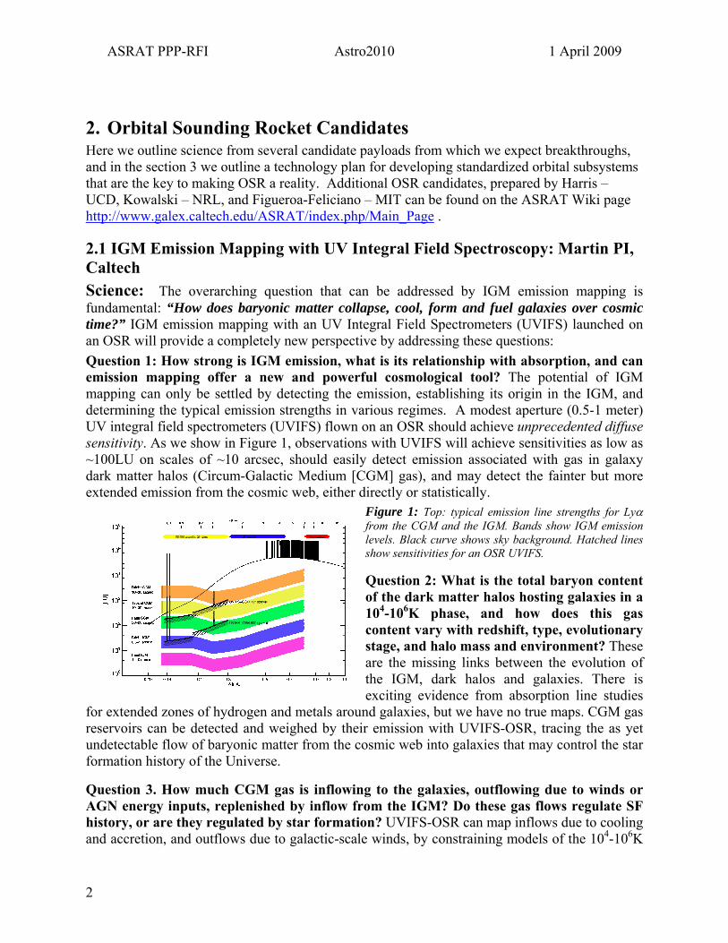
2.1 IGM Emission Mapping with UV Integral Field Spectroscopy: Martin PI, Caltech Science: The overarching question that can be addressed by IGM emission mapping is fundamental: “How does baryonic matter collapse, cool, form and fuel galaxies over cosmic time?” IGM emission mapping with an UV Integral Field Spectrometers (UVIFS) launched on an OSR will provide a completely new perspective by addressing these questions: Question 1: How strong is IGM emission, what is its relationship with absorption, and can emission mapping offer a new and powerful cosmological tool? The potential of IGM mapping can only be settled by detecting the emission, establishing its origin in the IGM, and determining the typical emission strengths in various regimes. A modest aperture (0.5-1 meter) UV integral field spectrometers (UVIFS) flown on an OSR should achieve unprecedented diffuse sensitivity. As we show in Figure 1, observations with UVIFS will achieve sensitivities as low as ~100LU on scales of ~10 arcsec, should easily detect emission associated with gas in galaxy dark matter halos (Circum-Galactic Medium [CGM] gas), and may detect the fainter but more extended emission from the cosmic web, either directly or statistically.
Figure 1: Top: typical emission line strengths for Lyα from the CGM and the IGM. Bands show IGM emission levels. Black curve shows sky background. Hatched lines show sensitivities for an OSR UVIFS.
Question 2: What is the total baryon content of the dark matter halos hosting galaxies in a 104-106K phase, and how does this gas content vary with redshift, type, evolutionary stage, and halo mass and environment? These are the missing links between the evolution of the IGM, dark halos and galaxies. There is exciting evidence from absorption line studies
for extended zones of hydrogen and metals around galaxies, but we have no true maps. CGM gas reservoirs can be detected and weighed by their emission with UVIFS-OSR, tracing the as yet undetectable flow of baryonic matter from the cosmic web into galaxies that may control the star formation history of the Universe.
Question 3. How much CGM gas is inflowing to the galaxies, outflowing due to winds or AGN energy inputs, replenished by inflow from the IGM? Do these gas flows regulate SF history, or are they regulated by star formation? UVIFS-OSR can map inflows due to cooling and accretion, and outflows due to galactic-scale winds, by constraining models of the 104-106K
2
ASRAT PPP-RFI Astro2010 1 April 2009
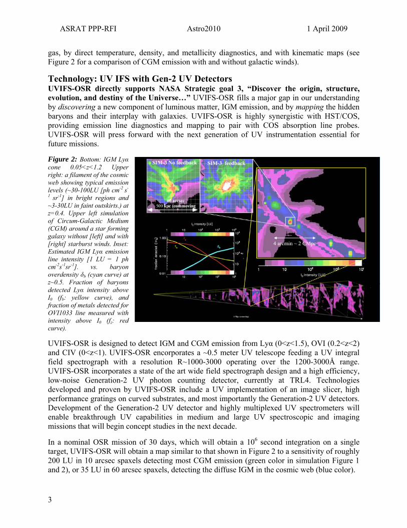
gas, by direct temperature, density, and metallicity diagnostics, and with kinematic maps (see Figure 2 for a comparison of CGM emission with and without galactic winds).
Technology: UV IFS with Gen-2 UV Detectors UVIFS-OSR directly supports NASA Strategic goal 3, “Discover the origin, structure, evolution, and destiny of the Universe…” UVIFS-OSR fills a major gap in our understanding by discovering a new component of luminous matter, IGM emission, and by mapping the hidden baryons and their interplay with galaxies. UVIFS-OSR is highly synergistic with HST/COS, providing emission line diagnostics and mapping to pair with COS absorption line probes. UVIFS-OSR will press forward with the next generation of UV instrumentation essential for future missions.
Figure 2: Bottom: IGM Lyα cone 0.05<z<1.2 Upper right: a filament of the cosmic web showing typical emission levels (~30-100LU [ph cm-2 s-
1 sr-1] in bright regions and ~3-30LU in faint outskirts.) at z=0.4. Upper left simulation of Circum-Galactic Medium (CGM) around a star forming galaxy without [left] and with [right] starburst winds. Inset: Estimated IGM Lyα emission line intensity [1 LU = 1 ph cm-2s-1sr-1]. vs. baryon overdensity δb (cyan curve) at z~0.5. Fraction of baryons detected Lyα intensity above I0 (fb: yellow curve), and fraction of metals detected for OVI1033 line measured with intensity above I0 (fz: red curve).
UVIFS-OSR is designed to detect IGM and CGM emission from Lyα (0<z<1.5), OVI (0.2<z<2) and CIV (0<z<1). UVIFS-OSR encorporates a ~0.5 meter UV telescope feeding a UV integral field spectrograph with a resolution R~1000-3000 operating over the 1200-3000Å range. UVIFS-OSR incorporates a state of the art wide field spectrograph design and a high efficiency, low-noise Generation-2 UV photon counting detector, currently at TRL4. Technologies developed and proven by UVIFS-OSR include a UV implementation of an image slicer, high performance gratings on curved substrates, and most importantly the Generation-2 UV detectors. Development of the Generation-2 UV detector and highly multiplexed UV spectrometers will enable breakthrough UV capabilities in medium and large UV spectroscopic and imaging missions that will begin concept studies in the next decade.
In a nominal OSR mission of 30 days, which will obtain a 106 second integration on a single target, UVIFS-OSR will obtain a map similar to that shown in Figure 2 to a sensitivity of roughly 200 LU in 10 arcsec spaxels detecting most CGM emission (green color in simulation Figure 1 and 2), or 35 LU in 60 arcsec spaxels, detecting the diffuse IGM in the cosmic web (blue color).
3

ASRAT PPP-RFI Astro2010 1 April 2009
2.2 Project Lyman at Low Redshift (0.02 < z < 0.4): McCandliss PI, JHU Science: Quantification of the LyC escape fraction (fe) from star forming galaxies is at the frontier of reionization physics. LyC escape is mysterious because mean H I column densities for normal galaxies are NHI > 1021 cm-2 yet it takes only a column of NHI = 1.6 x 1017 cm-2 to produce an optical depth of unity at the Lyman edge. Escape from such large mean optical depths requires the galaxy’s interstellar medium (ISM) to be highly inhomogeneous. Resolving this mystery is crucial to our understanding of the reionization epoch. Question 1. What are the relative contributions of quasars, active galactic nuclei and star-forming galaxies to the metagalactic ionizing background (MIB) across cosmic time. We know the universe has been reionized (Fan 2006, Spergel 2007). The question of how and when is of crucial importance for the formation of large scale structure at later epochs. The relative roles of star-forming galaxies, active galactic nuclei and quasars in contributing to the MIB remain uncertain. Deep quasar counts suggest there are too few to significantly contribute to reionization, but the potentially crucial contribution from the faint and apparently numerous star-forming galaxies (Yan & Windhorst 2004) is highly uncertain due to our poor understanding of the physics that allows ionizing radiation to escape into the intergalactic medium (IGM). Question 2. What is the relationship between fe and the local and global galactic parameters of metallicity, gas fraction, dust content, star formation history, mass, luminosity, redshift, over-density and quasar proximity in the redshift range 0.02 < z < 0.4. Direct observation at redshifts z > 3 of Lyman continuum (LyC) radiation emitted below the H I ionization edge at 912 Å becomes increasingly improbable due to the increase of intervening Ly limit systems. This favors UV and U-band optical observations in efforts to directly identify the environmental characteristics that aid LyC escape. In particular, low redshift observations at 0.02 < z < 0.4 have the best chance of yielding spatially resolved insight into the relationships between the LyC escape and local and global parameters such as, metallicity, gas fraction, dust content, star formation history, mass, luminosity, redshift, over-density and quasar proximity. Question 3. Do low-z analogs exist of the faint high-z galaxies responsible for reionization? Efforts to observe LyC emission from star-forming galaxies have returned mixed results, but hint at a trend for fe falling towards low-z (see McCandliss et al. 2009 for a review). This may be due the lack of well-formed neutral disks around galaxies at earlier epochs. At lower redshifts (0 ≤ z ≤ 1.5), giant H I disks have begun to settle and outflows are significantly smaller, resulting in lower fe due to the higher density of H I surrounding H II regions. Some expect a trend whereby metal-poor dwarfs and irregulars have higher fe than bulge and disk type galaxies because they t reside predominately on the outskirts of galactic clusters where the IGM is more tenuous and has a higher ionization fraction. These objects may be low-z analogs to the low mass LyC emitting objects at high-z claimed to drive reionization. Searching for low-z analogs can be carried out efficiently from a wide-field far-UV spectroscopic survey; discovery would be phenomenal. Question 4. Can the escape fraction of Lyα photons (fα) serve as a proxy for fe? It is not clear whether we should expect a correlation or an anti-correlation of LyC and Lyα emission, because the intensity of Lyα is proportional to the number of LyC photons that do NOT escape. Yet many of the processes that allow LyC to escape, such as an inhomogeneous multiphase ISM, also aid Lyα escape. Determining if such a relation exists is extremely
4
ASRAT PPP-RFI Astro2010 1 April 2009
important to the James Webb Space Telescope (JWST) key goal of identifying the sources responsible for initiating and completing the epoch of reionization. Lyα emission is thought to be a beacon for the formation of structure (Furlanetto et al. 2005
important to the James Webb Space Telescope (JWST) key goal of identifying the sources responsible for initiating and completing the epoch of reionization. Lyα emission is thought to be a beacon for the formation of structure (Furlanetto et al. 2005) in all epochs. It is the primary ionization diagnostic available to JWST and may provide a detailed view of the beginning of the reionization era (Stiavelli et al. 2004) at redshifts z > 6. Technology: McCandliss et al. (2008) quantified the requirements for detecting LyC leak in L*
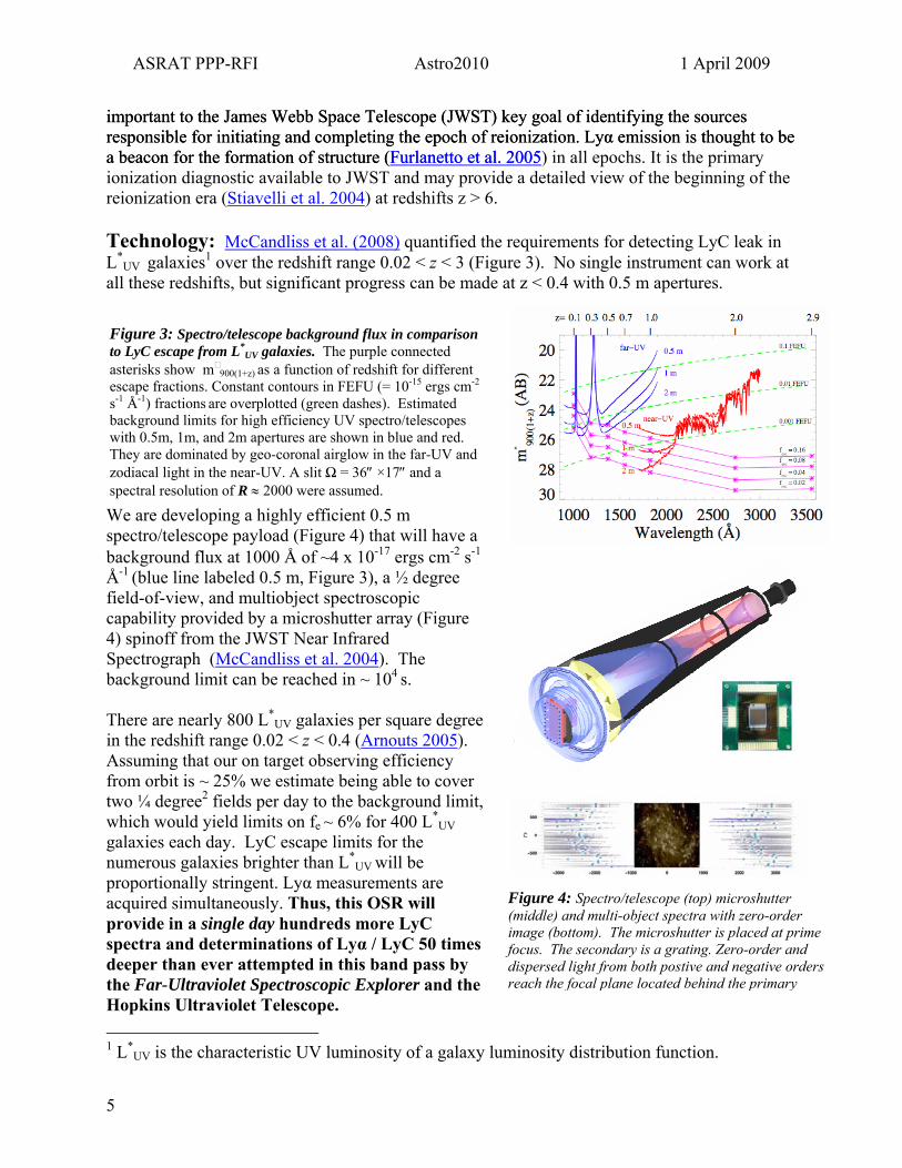
UV galaxies1 over the redshift range 0.02 < z < 3 (Figure 3). No single instrument can work at all these redshifts, but significant progress can be made at z < 0.4 with 0.5 m apertures.
5
Figure 3: Spectro/telescope background flux in comparison to LyC escape from L galaxies. *
UV The purple connected asterisks show m 900(1+z) as a function of redshift for different escape fractions. Constant contours in FEFU (= 10-15 ergs cm-2 s-1 Å-1) fractions are overplotted (green dashes). Estimated background limits for high efficiency UV spectro/telescopes with 0.5m, 1m, and 2m apertures are shown in blue and red. They are dominated by geo-coronal airglow in the far-UV and zodiacal light in the near-UV. A slit Ω = 36″ ×17″ and a spectral resolution of R ≈ 2000 were assumed.
We are developing a highly efficient 0.5 m spectro/telescope payload (Figure 4) that will have a background flux at 1000 Å of ~4 x 10-17 ergs cm-2 s-1 Å-1 (blue line labeled 0.5 m, Figure 3), a ½ degree field-of-view, and multiobject spectroscopic capability provided by a microshutter array (Figure 4) spinoff from the JWST Near Infrared Spectrograph (McCandliss et al. 2004). The background limit can be reached in ~ 104 s. There are nearly 800 L*
UV galaxies per square degree in the redshift range 0.02 < z < 0.4 (Arnouts 2005). Assuming that our on target observing efficiency from orbit is ~ 25% we estimate being able to cover two ¼ degree2 fields per day to the background limit, which would yield limits on fe ~ 6% for 400 L*
UV galaxies each day. LyC escape limits for the numerous galaxies brighter than L*
UV will be proportionally stringent. Lyα measurements are acquired simultaneously. Thus, this OSR will provide in a single day hundreds more LyC spectra and determinations of Lyα / LyC 50 times deeper than ever attempted in this band pass by the Far-Ultraviolet Spectroscopic Explorer and the Hopkins Ultraviolet Telescope.
Figure 4: Spectro/telescope (top) microshutter (middle) and multi-object spectra with zero-order image (bottom). The microshutter is placed at prime focus. The secondary is a grating. Zero-order and dispersed light from both postive and negative orders reach the focal plane located behind the primary
1 L*
UV is the characteristic UV luminosity of a galaxy luminosity distribution function.

ASRAT PPP-RFI Astro2010 1 April 2009
2.3 Galactic Hot ISM Studies with Micro-X: Figueroa-Feliciano PI, MIT
Figure 5: Simulation of a high-latitude observation of the ISM with Micro-X.
Studies of the inter-stellar medium (ISM) address the following fundamental NASA Science Questions: How do planets, stars, galaxies, and cosmic structure come into being? When and how did the elements of life and the universe arise? The hot (T > 106 K) component of the ISM is crucial to our understanding of the entire ISM because it traces the bulk of the energy injected into the ISM by supernovae, yet it is still unclear how much hot gas there is and how it is distributed. Is the ISM a hot medium with cold embedded clouds or is it a predominately cold medium with embedded hot bubbles?
Question 1: How much hot gas is there in the galactic disk, and what is its source? In the 1/4 and 3/4 keV bands the neutral gas in the galactic disk strongly absorbs emission from outside the Galaxy. However, the observed X-ray surface brightness is relatively unchanged from high galactic latitudes to the galactic plane; a galactic component exists and almost completely compensates for the absorbed extra-galactic emission. Observations of other galaxies suggest that there is a pervasive diffuse component (even in inter-arm regions) and lines-of-sight terminating within the nearest 3 kpc suggest that some fraction of this emission is truly diffuse. More global surveys suggest a strong contribution from unresolved dwarf stars. The comparison of two high resolution spectra (~2 eV) of the diffuse and pseudo-diffuse emission at 0 and ~90 degrees to the galactic plane would provide plasma emission line diagnostics that would enable the characterization and separation of the disk and halo spectra. This would allow the determination of the source and quantity of the plasma producing the disk emission.
Question 2: Is there a hot halo? Galactic fountain models predict hot gas expelled from the disk into the halo, even though there is little observational evidence for the upflowing gas. ROSAT shadowing observations show that there is hot gas higher than 300 pc from the disk, but we have no evidence that the gas is in the halo, and not more distant. Low spectral resolution surveys with Chandra, XMM, and Suzaku provide inconsistent results, in part due to the contamination of the key temperature diagnostics by solar wind charge exchange (SWCX) emission. High-resolution spectroscopy (~2 eV) can isolate the effects of SWCX (different branches of the OVII triplet are populated by SWCX than by thermal emission) and allow direct measurements of temperatures using multiple line-based diagnostics. Not only will we be able to determine a temperature gradient, but the comparison of
6

ASRAT PPP-RFI Astro2010 1 April 2009
different temperature diagnostics would allow one to determine whether the gas is in equilibrium or not, none of which is possible with CCD resolution or grating spectrometers.
Question 3: Is there a Local Hot Bubble (LHB)? The sun is thought to be surrounded by a very irregular region nearly devoid of neutral gas (r~100 pc) that is filled with hot (106 K) gas, producing the strong 1/4 keV emission seen in the Galactic plane and towards nearby molecular clouds. However, since the ROSAT era it has become clear that the SWCX emission due to the interstellar neutrals flowing through the heliosphere provides an as yet unknown fraction of the emission previously attributed to the LHB. Like thermal emission, the SWCX spectrum is a line spectrum, and the two spectra are thought to be distinguishable at high spectral resolution. A temporal correlation of the spectral features towards a nearby molecular cloud (blocking more distant Galactic emission) with simultaneous measurements of the abundances in the solar wind sweeping past the earth (as provided, for example by ACE) would allow one to characterize and separate the SWCX and LHB spectra, and to resolve the question of the existence of the LHB.
Technology: Spectroscopy with a TES Microcalorimeter Instrument Figure 6: The suborbital Micro-X science instrument configured for X-ray background observations. The instrument as is will provide 30 hours of observation, limited by the liquid He lifetime in the cryostat.
Configured for diffuse X-ray background observations, Micro-X has a 256-pixel array of microcalorimeters with 2 eV resolution and a total area of 1 cm2. The energy bandpass of the instrument is 0.1-4 keV, low enough to capture the emission from 1x10⁶ K plasma. The array looks at the sky through a filter stack and an aperture that sets the field of view at 20 degrees. This allows enough localization of the emission to easily distinguish the polar region from the galactic plane. Figure 1 shows a simulation of a Micro-X observation of the galactic pole. A Micro-X OSR mission would perform various such pointings (10-16 ks each) to perform the science discussed above in a single 30 hour flight.
Micro-X offers a unique combination of spectral resolution, bandpass, and grasp. Including the filter response, Micro-X’s grasp is 200 cm2 deg2, twice the International X-ray Observatory (IXO) grasp of 100 cm2 deg2 at 0.6 keV. This small rocket payload attains the same energy resolution and twice the grasp of IXO a decade earlier and at very small fraction (~1/200th) of the cost. No current or approved mission in the coming decade (including Chandra, XMM, or Astro-H) can do this science.
The TES array requires a cryogenic system with a base temperature of 50 mK which uses a liquid He bath as its heat sink. Due to this consumable, our current system has a stand-alone operational time of ~30 hours. Assuming 50% on-target science efficiency in orbit, this would give us ~50 ks of observing time, equivalent to 167 rocket flights.
For ~$1M, a modified cryogenic tank would give the mission a 30-day lifetime, which would greatly increase the science capability and enable mapping of 85% of the sky at the same depth as our 50 ks observation.
7

ASRAT PPP-RFI Astro2010 1 April 2009
2.4 Understanding the Soft X-ray Background Using Diffuse X-ray Spectroscopy: McEntaffer PI, UIowa Science: The soft x-ray background (SXRB) is a mystery. We just do not understand it. Consequently, we must admit that we do not fully understand the energy balance in the Sun’s heliosphere, the Local Hot Bubble (LHB), the interstellar medium (ISM) and the galactic halo. The fundamental question that is addressed by studying this gas is: What is the nature of the local, hot ISM and what implications does this have for galactic ISM? Some of the soft x-ray background has been shown to be variable on a timescale of days and linked to solar activity, while some features are persistent and must originate in the Milky Way at much greater distances. But our best instruments have merely identified the problem. We do not even know if the emission mechanism is dominated by thermal bremsstrahlung or charge exchange. We need instruments that can begin to unravel this dilemma.
Question 1: What is the origin of the soft X-ray background Deconvolving the soft X-ray background can only be done with diffuse X-ray spectroscopy. This low energy emission identifies there is unabsorbed, highly anisotropic emission that is produced locally as shown in Figure 7. This emission exists in the plane of the galaxy in addition to enhancements at high latitude. However, its origin is completely unknown. Is the local component similar to the halo component? Why is it enhanced toward the galactic poles? What are the temperature, density and metallicity? What does this gas tell us about hot ISM in galaxies and intergalactic medium feedback mechanisms? These answers can only be addressed with high resolution X-ray spectroscopy.
Figure 7: 3-color ROSAT image of the galactic soft X-ray background
Question 2: Why does the soft X-ray background vary temporally. One of the most intriguing complexities of the soft X-ray background is that much of its flux is unexplained. ROSAT observed time-varying components dubbed as long term enhancements (LTEs; Snowden et al. 1994). Figure 8 displays that as much as 50% of the ¼ keV band flux can exist in these LTEs above the steady state flux. Cravens et al. (2001) show a strong correlation between solar wind proton flux and ROSAT ¼ keV LTEs. They produce a model of charge exchange X-ray emission and use solar wind parameters to accurately predict the flux and variability of ROSAT LTEs. Solar wind charge exchange (SWCX) occurs when neutral atoms in the heliosphere and Earth’s geocorona transfer
Figure 8: The dotted line shows the ROSAT count rate in the ¼ keV channel during a period from 1990. The solid line shows the measured solar wind proton flux for the same time period. The latter was scaled for a best comparison, but the scales are accurate.
8
ASRAT PPP-RFI Astro2010 1 April 2009
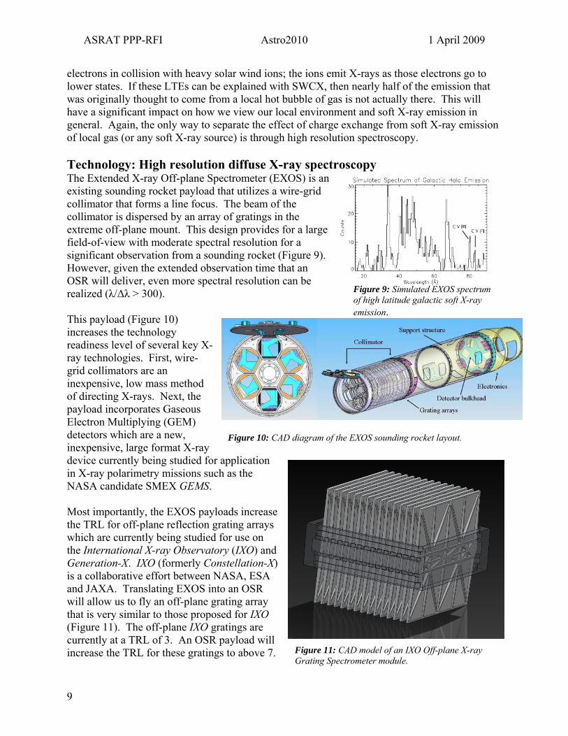
electrons in collision with heavy solar wind ions; the ions emit X-rays as those electrons go to lower states. If these LTEs can be explained with SWCX, then nearly half of the emission that was originally thought to come from a local hot bubble of gas is not actually there. This will have a significant impact on how we view our local environment and soft X-ray emission in general. Again, the only way to separate the effect of charge exchange from soft X-ray emission of local gas (or any soft X-ray source) is through high resolution spectroscopy. Technology: High resolution diffuse X-ray spectroscopy The Extended X-ray Off-plane Spectrometer (EXOS) is an existing sounding rocket payload that utilizes a wire-grid collimator that forms a line focus. The beam of the collimator is dispersed by an array of gratings in the extreme off-plane mount. This design provides for a large field-of-view with moderate spectral resolution for a significant observation from a sounding rocket (Figure 9). However, given the extended observation time that an OSR will deliver, even more spectral resolution can be realized (λ/∆λ > 300). Figure 9: Simulated EXOS spectrum
of high latitude galactic soft X-ray emission.
This payload (Figure 10) increases the technology readiness level of several key Xray technologies. First, wire-grid collimators are an inexpensive, low mass method of directing X-rays. Next, the payload incorporates Gaseous Electron Multiplying (GEM) detectors which are a new, inexpensive, large format X-ray device currently being studied for application in X-ray polarimetry missions such as the NASA candidate SMEX GEMS.
-
Figure 10: CAD diagram of the EXOS sounding rocket layout.
Most importantly, the EXOS payloads increase the TRL for off-plane reflection grating arrays which are currently being studied for use on the International X-ray Observatory (IXO) and Generation-X. IXO (formerly Constellation-X) is a collaborative effort between NASA, ESA and JAXA. Translating EXOS into an OSR will allow us to fly an off-plane grating array that is very similar to those proposed for IXO (Figure 11). The off-plane IXO gratings are currently at a TRL of 3. An OSR payload will increase the TRL for these gratings to above 7. Figure 11: CAD model of an IXO Off-plane X-ray
Grating Spectrometer module.
9
ASRAT PPP-RFI Astro2010 1 April 2009
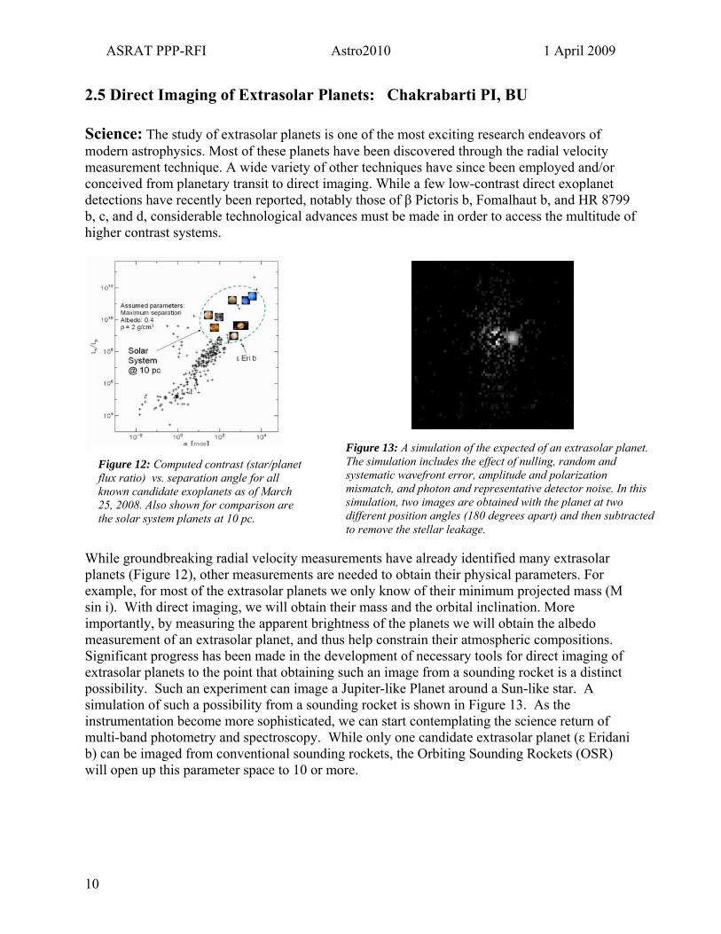
2.5 Direct Imaging of Extrasolar Planets: Chakrabarti PI, BU Science: The study of extrasolar planets is one of the most exciting research endeavors of modern astrophysics. Most of these planets have been discovered through the radial velocity measurement technique. A wide variety of other techniques have since been employed and/or conceived from planetary transit to direct imaging. While a few low-contrast direct exoplanet detections have recently been reported, notably those of β Pictoris b, Fomalhaut b, and HR 8799 b, c, and d, considerable technological advances must be made in order to access the multitude of higher contrast systems.
Figure 13: A simulation of the expected of an extrasolar planet. The simulation includes the effect of nulling, random and systematic wavefront error, amplitude and polarization mismatch, and photon and representative detector noise. In this simulation, two images are obtained with the planet at two different position angles (180 degrees apart) and then subtracted to remove the stellar leakage.
WpesimmSepsinmbw
1
Figure 12: Computed contrast (star/planet flux ratio) vs. separation angle for all known candidate exoplanets as of March 25, 2008. Also shown for comparison are the solar system planets at 10 pc.
hile groundbreaking radial velocity measurements have already identified many extrasolar lanets (Figure 12), other measurements are needed to obtain their physical parameters. For xample, for most of the extrasolar planets we only know of their minimum projected mass (M in i). With direct imaging, we will obtain their mass and the orbital inclination. More
portantly, by measuring the apparent brightness of the planets we will obtain the albedo easurement of an extrasolar planet, and thus help constrain their atmospheric compositions. ignificant progress has been made in the development of necessary tools for direct imaging of xtrasolar planets to the point that obtaining such an image from a sounding rocket is a distinct ossibility. Such an experiment can image a Jupiter-like Planet around a Sun-like star. A imulation of such a possibility from a sounding rocket is shown in Figure 13. As the strumentation become more sophisticated, we can start contemplating the science return of ulti-band photometry and spectroscopy. While only one candidate extrasolar planet (ε Eridani
) can be imaged from conventional sounding rockets, the Orbiting Sounding Rockets (OSR) ill open up this parameter space to 10 or more.
0
ASRAT PPP-RFI Astro2010 1 April 2009
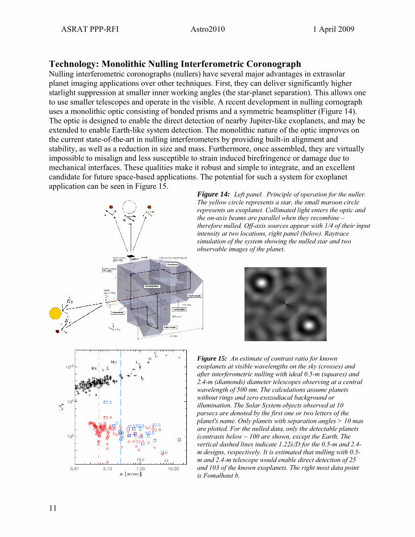
Technology: Monolithic Nulling Interferometric CoronographNulling interferometric coronographs (nullers) have several major advantages in extrasolar planet imaging applications over other techniques. First, they can deliver significantly higher starlight suppression at smaller inner working angles (the star-planet separation). This allows one to use smaller telescopes and operate in the visible. A recent development in nulling cornograph uses a monolithic optic consisting of bonded prisms and a symmetric beamsplitter (Figure 14). The optic is designed to enable the direct detection of nearby Jupiter-like exoplanets, and may be extended to enable Earth-like system detection. The monolithic nature of the optic improves on the current state-of-the-art in nulling interferometers by providing built-in alignment and stability, as well as a reduction in size and mass. Furthermore, once assembled, they are virtually impossible to misalign and less susceptible to strain induced birefringence or damage due to mechanical interfaces. These qualities make it robust and simple to integrate, and an excellent candidate for future space-based applications. The potential for such a system for exoplanet application can be seen in Figure 15.
11
Figure 14: Left panel. Principle of operation for the nuller. The yellow circle represents a star, the small maroon circle represents an exoplanet. Collimated light enters the optic and the on-axis beams are parallel when they recombine – therefore nulled. Off-axis sources appear with 1/4 of their input intensity at two locations, right panel (below). Raytrace simulation of the system showing the nulled star and two observable images of the planet.
Figure 15: An estimate of contrast ratio for known exoplanets at visible wavelengths on the sky (crosses) and after interferometric nulling with ideal 0.5-m (squares) and 2.4-m (diamonds) diameter telescopes observing at a central wavelength of 500 nm. The calculations assume planets without rings and zero exozodiacal background or illumination. The Solar System objects observed at 10 parsecs are denoted by the first one or two letters of the planet's name. Only planets with separation angles > 10 mas are plotted. For the nulled data, only the detectable planets (contrasts below ~ 100 are shown, except the Earth. The vertical dashed lines indicate 1.22λ/D for the 0.5-m and 2.4-m designs, respectively. It is estimated that nulling with 0.5-m and 2.4-m telescope would enable direct detection of 25 and 103 of the known exoplanets. The right most data point is Fomalhaut b.

ASRAT PPP-RFI Astro2010 1 April 2009
3. Design Principles and Technology Drivers for OSR The NASA SR program has maintained over five decades a low-cost program for providing frequent opportunities to space research scientists in a variety of disciplines. The program, which has an annual budget of about $40M, maintains a launch rate of ~ 25 per year. The risk mitigation principles that have yielded a success rate of 85% and sustained a low-cost operation are:
• Employ standardized sub-systems wherever possible. • Select commercial off-the-shelf components and sub-systems, modify them as needed for
space operations, and employ thorough, in house, environmental and functional testing. • Maintain engineering teams with extensive experience from past missions and a thorough
understanding of the standardized sub-systems, and who control paperwork to the minimum demanded by the engineering operations.
The extension of the program to OSR missions will maintain these principles, and make the adjustments necessary for transition to longer flights in space. The basic requirements for OSR delivery and support systems is that it replicate the high functionality of the BB IX and sub-systems in low earth orbit (LEO) for up to 30 days at low cost. Thirty days represents a threshold for electronic damage, longer than which radiation upsets becomes worrisome. Most modern astrophysics payloads have masses ~ 420 kg, including subsystems, and require 3-axis maneuvering and pointing with sub-arcsecond stability. We list strawman design criteria here:
Figure16: Top - The Falcon 1 vehicle installed on the launch pad at Omelek island. This was for the third mission F1-003. The elevated platform is being use for installation of electrical umbilicals and a duct used for payload environment control. Bottom – The Falcon1 and 1e performance curves.
• Experiment Mass:
o ~ 150 kg (without subsystems) • Experiment Volume:
o 2.2 m length, 0.56 m diameter • Data Rate (primary science):
o 0.5 -- 1 Gbyte day-1 • Experiment Power (orbit avg)
o 3.25 Amps @ 28 Volts • Pointing
o 1′′ -- 2′′ stability per orbit o 1′ accuracy
• Duration o 1 day for minimum success o 1 month for comprehensive success
12

ASRAT PPP-RFI Astro2010 1 April 2009
3.1. Launch Vehicle OSR needs a small launch vehicle capable of putting 420 kg into LEO. There are only two vehicles in this class, which have reached or are close to operational status. The Orbital Sciences Minotaur I has achieved 7 successful flights, and the SpaceX Falcon 1 after three failures achieved a successful flight in September 2008. However, the Minotaur I is under Air Force control, and their procedures for management, motor inspection and mission assurance result in a cost of $25-30 million. SpaceX has provided a letter to the Chairman of the NASA ASRAT stating that the cost of a Falcon 1 launched from Omelek in the Marshall Islands is $8.7M, which includes vehicle processing, test, launch and Army range safety operations. The design of Falcon 1 (Figure 16) incorporates the experience of decades of liquid-propellent rocketry. This, taken with its cost, currently makes Falcon 1 the preferred OSR launch vehicle. However, this depends on the continued success of its launch program, and a successful application to the NASA Launch Services (NLS) Flight Planning Board for an FAA licensed launch. FAA licensed launches place mission assurance in the hands of the organization procuring the vehicle, and avoids NLS procurement procedures that would effectively double the vehicle cost. An improved version of the vehicle, the Falcon 1e, will be available in the near future at an additional cost of ~$1M, which will can more than double the mass injected into LEO and accommodate significantly longer science instruments; significant factors where astrophysics and solar telescopes are concerned. A major objective of the program is to carry out OSR missions at a rate of 1 per year. Each mission could fly one primary science payload and a number of small secondary payloads (e.g. CubeSats).
13
3.2. Payload Support Development
The design of the OSR payload is based, wherever possible, on the technology developed for sounding rockets (SR) and proven in over a decade of flight experience. However, the longer duration of an orbital flight lasting up to 30 days poses new requirements, which must be met by modifying old or by developing new sub-systems. This approach was proven in the 1980s and 1990s, when the SR engineering teams at the Goddard Space Flight Center used their experience and the infrastructure at GSFC to prepare low-cost payloads for shuttle missions. The Spartan free-flying payload, and the Hitchhiker and Getaway Special payloads mounted in the shuttle bay, enabled SR science instruments to increase observing time in space by factors of 100-1000.
Figure 17: Strawman astronomy payload.
Keeping costs down plays an important role in the modification and development of standardized sub-systems for these OSR missions. While there exist a host of challenges for developing low cost systems for OSR with the required performance, three systems standout:
I. Attitude control. II. Command and data handling – mission operations.
III. Electrical power.
ASRAT PPP-RFI Astro2010 1 April 2009
Two other aspects of OSR missions will also need to be addressed carefully, namely thermal control and design for complete burn-up during re-entry (‘demisability’). However, these areas require no major new technical developments. A strawman payload is shown in Figure 17.
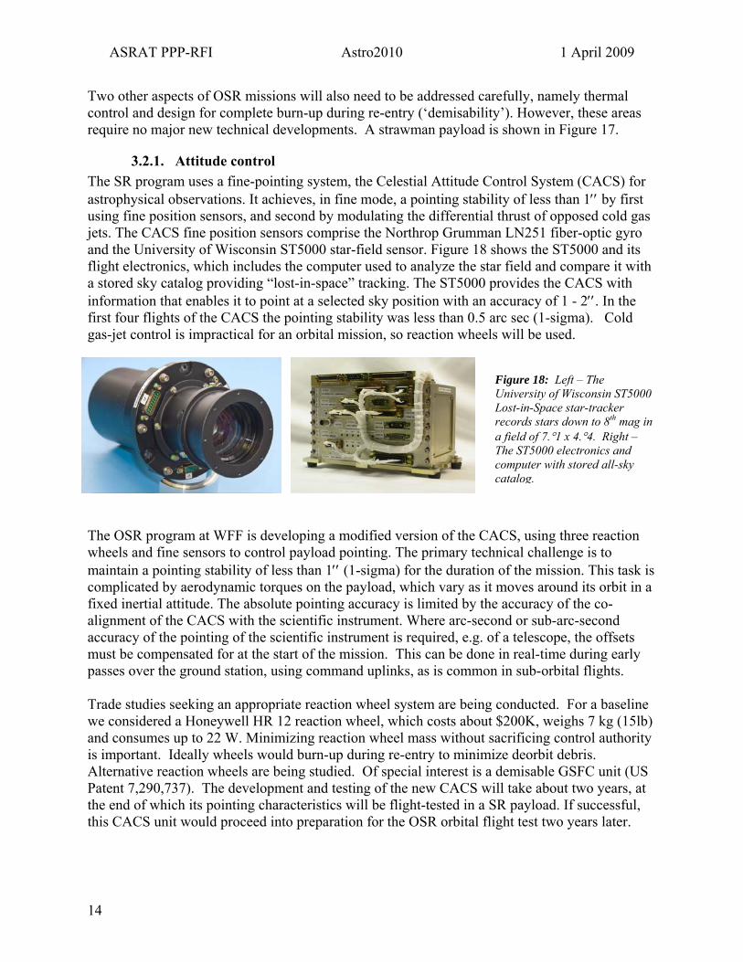
3.2.1. Attitude control The SR program uses a fine-pointing system, the Celestial Attitude Control System (CACS) for astrophysical observations. It achieves, in fine mode, a pointing stability of less than 1′′ by first using fine position sensors, and second by modulating the differential thrust of opposed cold gas jets. The CACS fine position sensors comprise the Northrop Grumman LN251 fiber-optic gyro and the University of Wisconsin ST5000 star-field sensor. Figure 18 shows the ST5000 and its flight electronics, which includes the computer used to analyze the star field and compare it with a stored sky catalog providing “lost-in-space” tracking. The ST5000 provides the CACS with information that enables it to point at a selected sky position with an accuracy of 1 - 2′′. In the first four flights of the CACS the pointing stability was less than 0.5 arc sec (1-sigma). Cold gas-jet control is impractical for an orbital mission, so reaction wheels will be used.
Figure 18: Left – The University of Wisconsin ST5000 Lost-in-Space star-tracker records stars down to 8th mag ia field of 7.°1 x 4.°4. Right – The ST5000 electronics and computer with stored all-sky catalo
n
g.
The OSR program at WFF is developing a modified version of the CACS, using three reaction wheels and fine sensors to control payload pointing. The primary technical challenge is to maintain a pointing stability of less than 1′′ (1-sigma) for the duration of the mission. This task is complicated by aerodynamic torques on the payload, which vary as it moves around its orbit in a fixed inertial attitude. The absolute pointing accuracy is limited by the accuracy of the co-alignment of the CACS with the scientific instrument. Where arc-second or sub-arc-second accuracy of the pointing of the scientific instrument is required, e.g. of a telescope, the offsets must be compensated for at the start of the mission. This can be done in real-time during early passes over the ground station, using command uplinks, as is common in sub-orbital flights. Trade studies seeking an appropriate reaction wheel system are being conducted. For a baseline we considered a Honeywell HR 12 reaction wheel, which costs about $200K, weighs 7 kg (15lb) and consumes up to 22 W. Minimizing reaction wheel mass without sacrificing control authority is important. Ideally wheels would burn-up during re-entry to minimize deorbit debris. Alternative reaction wheels are being studied. Of special interest is a demisable GSFC unit (US Patent 7,290,737). The development and testing of the new CACS will take about two years, at the end of which its pointing characteristics will be flight-tested in a SR payload. If successful, this CACS unit would proceed into preparation for the OSR orbital flight test two years later.
14
ASRAT PPP-RFI Astro2010 1 April 2009
3.2.2. Command and Data Handling (C&DH) The SR science data rate is determined by the characteristics of the PCM data encoder and the S-band data link, and the current limit is about 10 Mb/s. In an orbital mission data must be stored on board and then transmitted to ground either via the TDRSS satellite system or during ground station (GS) passes. The goal of OSR is simplicity and low cost, and it is planned to downlink data once per day, during 3-4 passes within range of the Wallops GS. Using S-band downlink about 1.2 GBytes of data can be transmitted, corresponding to an orbital average data sampling rate of ~ 200 kb/s. S-band can also be employed to uplink spacecraft pointing scripts as needed. X-band is also being considered to support the downlink of large quantities of stored data from new instruments with high spatial, spectral and time resolution requirements. X-band can downlink at least 17 GB daily, corresponding to an orbital average data sampling rate of ~ 1.6 Mb/s. WFF has large antennae and receivers operating at both X-band and S-band frequencies. OSR plans to use the very successful CREAM mission control center (MCC), developed for communications with a polar long-duration (LD) balloon payload. It will both process the payload data transmitted by OSR to ground via an X-band link, and handle the S-band command link. The MCC displays payload data real-time during OSR passes over WFF, transmits the science data to a remote center at the science PI institution, and archives all mission data. The development of this ORS C&DH system will require about two years, after which it will be flight tested in the same sounding rocket mission employed to test the new CACS. If this test is successful, the C&DH system would be prepared for the OSR orbital flight test two years later.
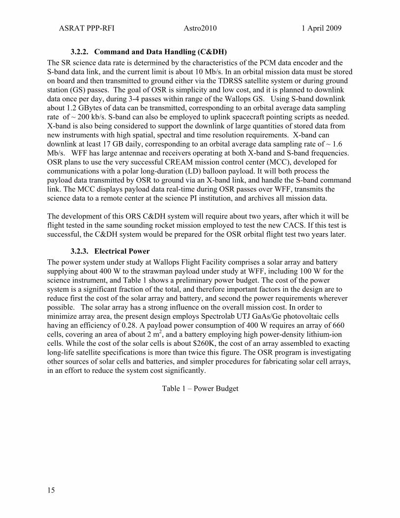
3.2.3. Electrical Power The power system under study at Wallops Flight Facility comprises a solar array and battery supplying about 400 W to the strawman payload under study at WFF, including 100 W for the science instrument, and Table 1 shows a preliminary power budget. The cost of the power system is a significant fraction of the total, and therefore important factors in the design are to reduce first the cost of the solar array and battery, and second the power requirements wherever possible. The solar array has a strong influence on the overall mission cost. In order to minimize array area, the present design employs Spectrolab UTJ GaAs/Ge photovoltaic cells having an efficiency of 0.28. A payload power consumption of 400 W requires an array of 660 cells, covering an area of about 2 m2, and a battery employing high power-density lithium-ion cells. While the cost of the solar cells is about $260K, the cost of an array assembled to exacting long-life satellite specifications is more than twice this figure. The OSR program is investigating other sources of solar cells and batteries, and simpler procedures for fabricating solar cell arrays, in an effort to reduce the system cost significantly.
Table 1 – Power Budget
15
ASRAT PPP-RFI Astro2010 1 April 2009
Component / Sub-system Power (Orbit Avg) W Science experiment (to be reviewed) 100
Attitude control system (ACS) 187 Flight computer and on-board storage memory bank 12
PCM encoder and telemetry monitor 10 X-band modulator and power amplifier 8
S-band command receiver and transmitter 3 GPS receiver 3.5
Current sensors 2.5 Power sub-system logic circuits 7
Thermal control 25 Total 358
Total with 20% contingency margin 430
16

ASRAT PPP-RFI Astro2010 1 April 2009
4. Organization of OSR at the Wallops Flight Facility The organization of this activity is shown in Figure 19. The Sounding Rocket Program Office (SRPO: Code 810) at the Wallops Flight Facility (WFF) carries out all its engineering activities through a NASA Sounding Rocket Operations Contract (NSROC), which engages a number of aerospace contractors, at present principally Northrop Grumman. OSR missions will receive strong support from other NASA offices at WFF, principally the Applied Engineering and Technology Directorate (AETD: Code 500), which has experience in satellite design and operations, and the Range and Mission Management Office (RMMO: Code 840).
Figure 19: OSR Activit y Organization
ASRAT MembersUniversity, Laboratory, and Industry
Sounding Rocket Project OfficeCode 810: WFF
NSROCWFF
AETDCode 500 GSFC
RMMOCode 840 WFF
NASA HQScience Mission Directorate
The NSROC engineering teams, and the SR integration and test (I&T) facilities, are located in Building F-10, which integrates mission analysis and planning, design and test of the various sub-systems, functional integration of the whole payload, including the science instrument, and environmental testing of the complete payload, including vibration testing, bend tests, spin balance and CG/moment of inertia measurements.
The OSR program will maintain a cleaner environment for payload assembly and electrical functional tests, which will be performed in a large, Class 100,000 clean room in Building F-7. It contains a smaller Class 10,000 tent, which can be used for special operations, e.g. science instrument assembly/disassembly. F-7 contains additional facilities for:
• Thermal vacuum tests – the chamber now available would be satisfactory for OSR sub-systems only. A larger NASA-surplus chamber is being acquired.
• Electromagnetic interference (EMI) and antenna tests. • Fabrication of multi-layer thermal blankets.
WFF has the advantage of operational efficiency, which impacts mission cost, in that all the facilities needed for an OSR mission are at one NASA center. The Wallops Island launch range (Figure 3) includes buildings for vehicle and payload processing, and a launch control center and blockhouse. A LO2 tank suitable for a Falcon 1 mission is being acquired, and plans have been made for providing RP-1 kerosene fuel. Modification of the Wallops range will require a capital investment, and for the first mission the OSR program may select Omelek as the launch site, in order to meet the program budget and schedule. In this scenario the payload would proceed through a full I&T program at WFF, and then be transported to Omelek for vehicle integration and launch.
5. Activity Schedule The first objective of the OSR program is to complete a ‘proof-of-concept’ orbital mission having the following milestones:
• Demonstrate that the mission cost meets target: $15M • Verify that all sub-systems in the payload meet design specifications.
17

ASRAT PPP-RFI Astro2010 1 April 2009
• Successful observations by a selected science instrument on-board. • Development of the procedures and equipment needed for all I&T, launch and mission
operations. We envision a project lasting 4 years, divided into two phases. The first proceeds through FY 2009 and 2010, and would be devoted to the major sub-system developments described in Section 3 followed by a flight test on a sounding rocket. The second phase comprises the preparation of flight sub-systems, I&T of the flight payload, and finally the vehicle integration, test and launch of an OSR payload. A successful completion of this mission by the NASA sounding rocket program would pave the way to a program providing regular orbital mission opportunities to experimenters.
6. Cost Estimates OSR is a new initiative, funded only at the concept level by WFF. It was initiated upon receiving permission from NASA HQ to support inquires made by the Astrophysics Sounding Rocket Assessment Team into the feasibility of advancing an OSR program. These concept studies have established technical feasibility, identified several “tall poles’’, presented a timeline for development, and made a budgetary estimate based on previous experience building support system hardware for payloads. They confirm that the cost of an orbital mission should not exceed $15.M, not counting science instrument costs incurred in the development of the sub-orbital precursor payloads. Non-recurring costs for developing to TRL7 the pointing, power, C&D and thermal subsystems, for the 1st flight demonstration, are estimated to be ~ $10.6M over a four year period. The high level recurring costs are provided in the Table 2.
Table 2 – Recurring Cost Estimates SYSTEM RECURRING COSTWFF Support Systems $ 3,300 K * Launch Vehicle & Range Cost $ 10,000 K ** Experiment Cost (mod for orbital flight) $ 1,000 K On-Orbit Ops Cost $ 100 K Misc / Contingency $ 1,000 K TOTAL $ 15,400 K *Cost Based on WFF OSR Study, 1/15/2009. Development+1st flight demonstration = $26M **Launch vehicle cost based on Space X response to inquiry. In Table 3 we compare the costs associated with supporting ten sub-orbital sounding rockets (roughly the recommended rate for a revitalized sounding rocket program, see ASRAT 2009), to those for supporting one OSR along with a total exposure time comparison. For the OSR we have assumed a total on-target time of 3.5 days for the OSR, which is roughly what could be accomplished in 14 days with a 25% observing efficiency. The 100:1 ratio in exposure time return will be highly attractive to the community, providing a developmental lure to the SR program along with a risk mitigation platform and cost containment for the development of potential Explorer missions.
18
ASRAT PPP-RFI Astro2010 1 April 2009
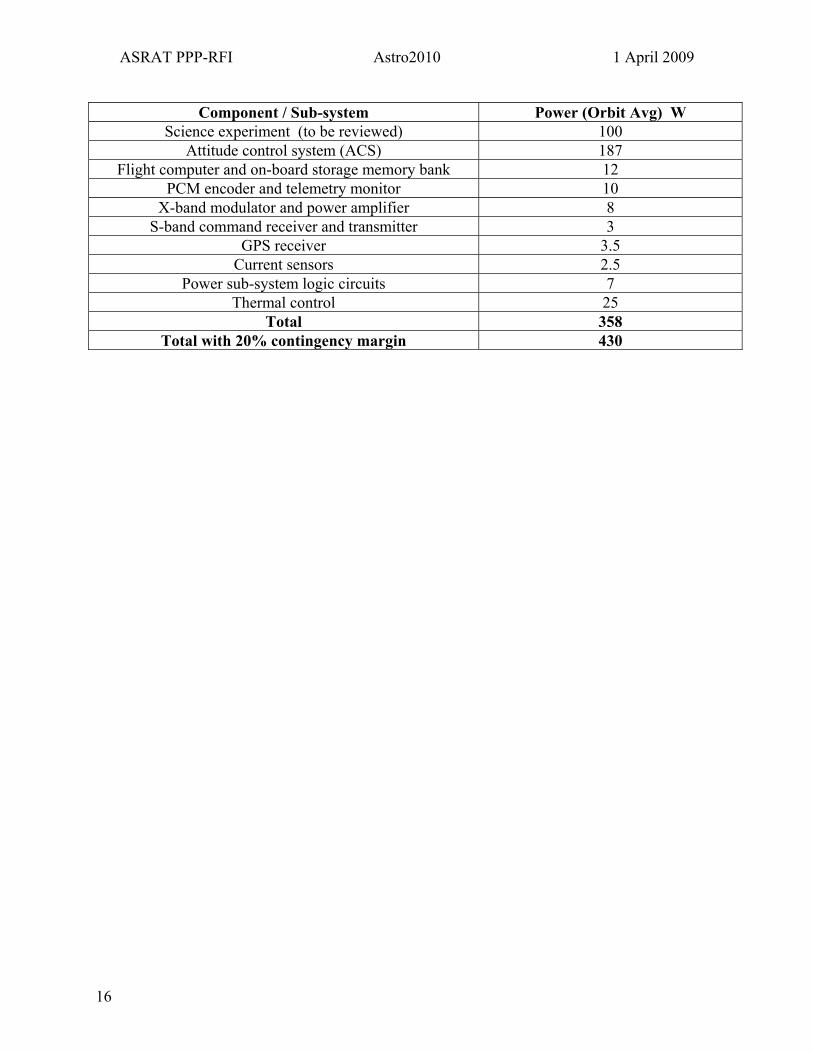
Table 3 – Sub-orbital and Orbital Cost and Exposure Time Comparison
Astrophysics Sounding Rocket Total Program Costs
Sub-orbital Sounding Rockets
Orbital Sounding Rockets
Flight Rate 10 1 Payload Costs (R&A) per flight $0.5M $1M Payload Support Costs per flight $1.2M $4M Launch Vehicle Costs per flight $0.3M $10M
Total per flight $2M $15M Program Costs/year $20M $15M
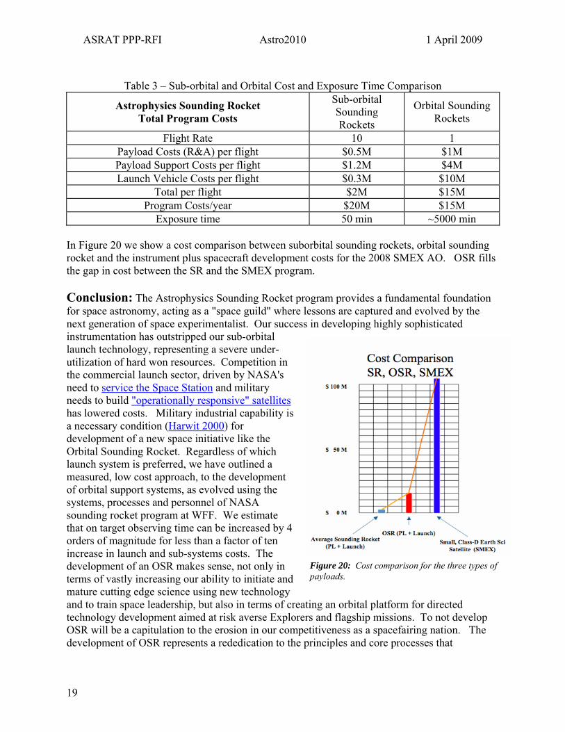
Exposure time 50 min ~5000 min In Figure 20 we show a cost comparison between suborbital sounding rockets, orbital sounding rocket and the instrument plus spacecraft development costs for the 2008 SMEX AO. OSR fills the gap in cost between the SR and the SMEX program. Conclusion: The Astrophysics Sounding Rocket program provides a fundamental foundation for space astronomy, acting as a "space guild" where lessons are captured and evolved by the next generation of space experimentalist. Our success in developing highly sophisticated instrumentation has outstripped our sub-orbital launch technology, representing a severe under-utilization of hard won resources. Competition in the commercial launch sector, driven by NASA's need to service the Space Station and military needs to build "operationally responsive" satellites has lowered costs. Military industrial capability is a necessary condition (Harwit 2000) for development of a new space initiative like the Orbital Sounding Rocket. Regardless of which launch system is preferred, we have outlined a measured, low cost approach, to the development of orbital support systems, as evolved using the systems, processes and personnel of NASA sounding rocket program at WFF. We estimate that on target observing time can be increased by 4 orders of magnitude for less than a factor of ten increase in launch and sub-systems costs. The development of an OSR makes sense, not only in terms of vastly increasing our ability to initiate and mature cutting edge science using new technology and to train space leadership, but also in terms of creating an orbital platform for directed technology development aimed at risk averse Explorers and flagship missions. To not develop OSR will be a capitulation to the erosion in our competitiveness as a spacefairing nation. The development of OSR represents a rededication to the principles and core processes that
Figure 20: Cost comparison for the three types of payloads.
19

ASRAT PPP-RFI Astro2010 1 April 2009
established our as nation the preeminent leader in space astronomy and will payoff dramatically in the scope, cost-effectiveness and discovery potential of NASA's future missions.
20