development of an innovative measurement system for
TRANSCRIPT

1 23
e & i Elektrotechnik undInformationstechnik ISSN 0932-383X Elektrotech. Inftech.DOI 10.1007/s00502-018-0670-z
Development of an innovativemeasurement system for audible noisemonitoring of OHL
Uwe Schichler, W. Troppauer,B. Fischer, T. Heine, Klemens Reich,M. Leonhardsberger & O. Oberzaucher

1 23
Your article is protected by copyright andall rights are held exclusively by CIGRE- Reprint from www.cigre.org with kindpermission. This e-offprint is for personaluse only and shall not be self-archivedin electronic repositories. If you wish toself-archive your article, please use theaccepted manuscript version for posting onyour own website. You may further depositthe accepted manuscript version in anyrepository, provided it is only made publiclyavailable 12 months after official publicationor later and provided acknowledgement isgiven to the original source of publicationand a link is inserted to the published articleon Springer's website. The link must beaccompanied by the following text: "The finalpublication is available at link.springer.com”.

Elektrotechnik & Informationstechnik https://doi.org/10.1007/s00502-018-0670-z CIGRE 2018
Development of an innovativemeasurement system for audible noisemonitoring of OHLU. Schichler OVE, W. Troppauer, B. Fischer, T. Heine, K. Reich OVE, M. Leonhardsberger OVE, O. Oberzaucher
Austrian Power Grid (APG), the main TSO of Austria, uses different approaches to face challenges arising from stricter requirementsregarding environmental issues, where audible noise (AN) is one of the important topics in this context.
A innovative approach is pursued with a newly developed measurement system for audible noise monitoring of OHL. The maincomponent of this system is an “optical microphone”. The main benefit compared to a conventional capacitive-microphone, is thelack of any metal and moving parts. Thus, it can operate in the proximity of high electric fields without interferences. This opens upnew possibilities for AN measurement on energized OHL. That facilitates the direct measurement of the acoustic immissions and notonly the emissions.
This is an advantage due to the fact, that measuring AN with conventional microphones has several limitations. The emitted noisefrom OHL is low compared to other emitters in the surroundings (cars, animals, farming, airplanes) and dependant on wind strengthand direction and hence difficult to measure. Furthermore, there is the need for a place on the ground to set up the microphones andthe power supply. An agreement with the landowners is mandatory.
For the operation of the optical microphone additional components are necessary. A special suspension system was developed tomount the sensor head in the direct vicinity of a conductor. One requirement for the suspension is to keep the sensor head at an exactposition underneath the conductor. In a close distance to the conductor, noise emissions vary in a wide range if the relative position isnot properly fixed. The second requirement is that the suspension system itself doesn’t influence the measurement. This means, thatthe electric field strength, which is a main parameter for AN, remains unchanged in the presence of the suspension system.
The paper will present the solutions and innovations that have been developed, laboratory tests and installation methods to mountthe optical microphone on a conductor.
Keywords: overhead line; corona; audible noise measurement; monitoring
© CIGRE - Reprint from www.cigre.org with kind permission 2018
1. IntroductionIn Austria there is no legal threshold value for AN from OHL, as forexample with railways, streets or airports. Therefore, for every per-mission procedure, a case-by-case examination is necessary. Overtime a certain methodology has been developed to counter thisproblem. Another issue is that nowadays people have become moresensitive regarding noise pollution. In this context AN emitted by ex-isting OHL has come more to the attention by residents, even thoughthey had already been previously living in the vicinity of an overheadline, some others even decided to move there.
APG and partners have initiated a project called ‘innovation-section’, which is a test run for new technical innovations to meetpersistent challenges [1]. This innovation-section is a 1,2 km longpart of an existing 380 kV double circuit line in Austria, whichwas rebuilt in 2016 from a standard OHL design to an insulatedcross-arms design and new conductors with special construction andtreated surface.
1.1 Issues regarding conventional AN measurementsAN-measurements are performed for three reasons.
• Due to constant complaints from neighbours of an OHL. In thiscase the AN measurement shall approve, that the OHL in questionis not lounder than other comparable OHLs.
• Comparative measurement before and after a refurbishment ofan OHL. Such measurements shall approve, that the refurbished
OHL is not louder than calculated in the forecast (e.g. part of EIApermitting procedures).
• Long term measurements for scientific use (to obtain a better un-derstanding of the acoustic behaviour of OHLs).
AN measurements in the open field faces several factors, that canheavily influence the outcome of the AN analysis.
First off, an agreement with the landowner of the area where themeasurement should be performed has to be found. If the measure-ment is done for the landowner, this should not be a problem. Inother cases this can lead to high compensations or the need for arelocation of the measurement point.
The dependency of a power supply near to the measurementsetup is another issue. For a long term measurement this means,that either a battery supply has to be changed in certain intervalsor some kind of infrastructure is in the surroundings, which impliesproblems with the selfnoise generated by this infrastructure.
0 0000 0. Jahrgang © CIGRE - Reprint from www.cigre.org with kind permission heft 0.0000
Paper submitted for the CIGRE Session 2018, SC B2, Paris, France, August 26–31, 2018.
Schichler, Uwe, Graz University of Technology, Graz, Austria; Troppauer, W., Mosdorfer,Weiz, Austria; Fischer, B., XARION Laser Acoustics, Wien, Austria; Heine, T., XARIONLaser Acoustics, Wien, Austria; Reich, Klemens, Austrian Power Grid AG, WagramerStraße 19, 1220 Wien, Austria (E-mail: [email protected]); Leonhardsberger, M.,Austrian Power Grid AG, Wien, Austria; Oberzaucher, O., Austrian Power Grid AG, Wien,Austria
Author's personal copy

CIGRE 2018 U. Schichler et al. Development of an innovative measurement system...
Fig. 1. Principle sketch of the of the measurement setup
AN that is not caused by the overhead line itself is the biggestissue for a conventional measurement setup. Examples are numer-ous: streets, railways, animals, creeks, farming or forests to list onlya few. These external factors make an effortful analysis of the datanecessary, to make sure that the outcome is not tampered. The big-ger the distance to the source of interest, in this case the OHL, thebigger the influence of external AN is. In theory, the sound level ofexternal interferences should at minimum be 10 dBs lower than thatof the source, to ensure the independency of the measurement [2].Considering a sound level of approximately 55 dB(A) underneath aOHL (distance of around 10 m to the conductors), the sound levelof other sources at the measurement point shouldn’t be louder than45 dB(A), which is very unlikely in the long term. For example, thebackground noise of the rain itself is often around 45 dB(A).
To handle the mentioned problems there are some possible waysto encounter them. The measurement points have to be chosen verywisely. Furthermore it is recommended to use multiple sound levelmeters at different locations to compensate external sound inter-ferences and the influence of wind direction and speed. A typicalexample would be one sound level meter directly under the OHL, asecond one in a distance of 30 m orthogonally to the line-axis anda third one in a distance of more than 100 m, to have a referencepoint for background noise and external interferences.
Typically an OHL only generates substantial AN under bad weatherconditions e.g. rain, fog or hoarfrost. Hence, for any kind of mea-surement setup it is required to measure for a longer period of time.The minimum measurement time at APG is one week, often an ex-tension to two weeks is required.
2. New approach for audible noise measurementIn the next step the innovation-section will be enhanced with anewly developed measurement system for audible noise monitoringof OHL. The main component of this system is a “membrane-freeoptical microphone”. The project has started in 2014 and the field
test is scheduled for 2018 and will bring valuable comparisons be-tween conventional and the optical microphone.
The main benefit of the optical microphone, compared to a con-ventional capacitive-microphone, is the lack of any metal and mov-ing parts. The absence of moving parts (such as a membrane,e.g.) allows to extend the measurement range into the ultrasoundregime. The absence of metallic parts, on the other hand, meansthat, it can operate in the proximity of high electric fields withoutinterferences. This opens up new possibilities for AN measurementon energized OHL, as the microphone can be placed within only afew dozen centimetres of the conductor. That facilitates the directmeasurement of the acoustic immissions and not only the emissions.
The control unit of the optical microphone is connected with datalogger by optical fibre. The logger continuously saves and transmitsthe collected data at the base of the tower. There the data is storedand can be read out anytime without switching off the line.
The optical microphone is mounted on a special suspension sys-tem on the conductor bundle. The optical fibre, which transmit thedata, is connected through a special hollow insulator to the tower.From the center of the tower the optical fibre is conducted to thebottom where the control unit and the data logger are situated. Apermanent power supply with 230 V is mandatory for the controlunit.
The whole arrangement of the measurement setup can be seenin Fig. 1.
3. Technical description of the optical microphoneThe optical microphone works on the principle of interferometry andconsists of a control unit containing a laser which sends its lightover an optical fibre to a sensor head. This sensor head consists ofa pair of parallel, semi reflective mirrors. Due to the difference inthe laser’s wave velocity depending on the air density in the hollowsensor head, the interference of the reflected light wave gives directand proportional information about the sound pressure level.
heft 0.0000 © CIGRE - Reprint from www.cigre.org with kind permission e&i elektrotechnik und informationstechnik
Author's personal copy
U. Schichler et al. Development of an innovative measurement system... CIGRE 2018
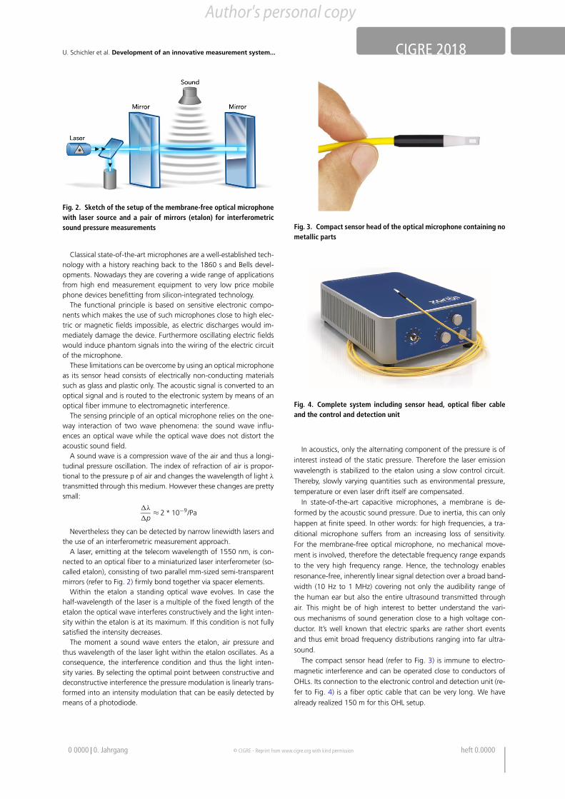
Fig. 2. Sketch of the setup of the membrane-free optical microphonewith laser source and a pair of mirrors (etalon) for interferometricsound pressure measurements
Classical state-of-the-art microphones are a well-established tech-nology with a history reaching back to the 1860 s and Bells devel-opments. Nowadays they are covering a wide range of applicationsfrom high end measurement equipment to very low price mobilephone devices benefitting from silicon-integrated technology.
The functional principle is based on sensitive electronic compo-nents which makes the use of such microphones close to high elec-tric or magnetic fields impossible, as electric discharges would im-mediately damage the device. Furthermore oscillating electric fieldswould induce phantom signals into the wiring of the electric circuitof the microphone.
These limitations can be overcome by using an optical microphoneas its sensor head consists of electrically non-conducting materialssuch as glass and plastic only. The acoustic signal is converted to anoptical signal and is routed to the electronic system by means of anoptical fiber immune to electromagnetic interference.
The sensing principle of an optical microphone relies on the one-way interaction of two wave phenomena: the sound wave influ-ences an optical wave while the optical wave does not distort theacoustic sound field.
A sound wave is a compression wave of the air and thus a longi-tudinal pressure oscillation. The index of refraction of air is propor-tional to the pressure p of air and changes the wavelength of light λ
transmitted through this medium. However these changes are prettysmall:
"λ
"p≈ 2 * 10−9/Pa
Nevertheless they can be detected by narrow linewidth lasers andthe use of an interferometric measurement approach.
A laser, emitting at the telecom wavelength of 1550 nm, is con-nected to an optical fiber to a miniaturized laser interferometer (so-called etalon), consisting of two parallel mm-sized semi-transparentmirrors (refer to Fig. 2) firmly bond together via spacer elements.
Within the etalon a standing optical wave evolves. In case thehalf-wavelength of the laser is a multiple of the fixed length of theetalon the optical wave interferes constructively and the light inten-sity within the etalon is at its maximum. If this condition is not fullysatisfied the intensity decreases.
The moment a sound wave enters the etalon, air pressure andthus wavelength of the laser light within the etalon oscillates. As aconsequence, the interference condition and thus the light inten-sity varies. By selecting the optimal point between constructive anddeconstructive interference the pressure modulation is linearly trans-formed into an intensity modulation that can be easily detected bymeans of a photodiode.
Fig. 3. Compact sensor head of the optical microphone containing nometallic parts
Fig. 4. Complete system including sensor head, optical fiber cableand the control and detection unit
In acoustics, only the alternating component of the pressure is ofinterest instead of the static pressure. Therefore the laser emissionwavelength is stabilized to the etalon using a slow control circuit.Thereby, slowly varying quantities such as environmental pressure,temperature or even laser drift itself are compensated.
In state-of-the-art capacitive microphones, a membrane is de-formed by the acoustic sound pressure. Due to inertia, this can onlyhappen at finite speed. In other words: for high frequencies, a tra-ditional microphone suffers from an increasing loss of sensitivity.For the membrane-free optical microphone, no mechanical move-ment is involved, therefore the detectable frequency range expandsto the very high frequency range. Hence, the technology enablesresonance-free, inherently linear signal detection over a broad band-width (10 Hz to 1 MHz) covering not only the audibility range ofthe human ear but also the entire ultrasound transmitted throughair. This might be of high interest to better understand the vari-ous mechanisms of sound generation close to a high voltage con-ductor. It’s well known that electric sparks are rather short eventsand thus emit broad frequency distributions ranging into far ultra-sound.
The compact sensor head (refer to Fig. 3) is immune to electro-magnetic interference and can be operated close to conductors ofOHLs. Its connection to the electronic control and detection unit (re-fer to Fig. 4) is a fiber optic cable that can be very long. We havealready realized 150 m for this OHL setup.
0 0000 0. Jahrgang © CIGRE - Reprint from www.cigre.org with kind permission heft 0.0000
Author's personal copy

CIGRE 2018 U. Schichler et al. Development of an innovative measurement system...
4. Technical description of the suspension of the microphone
4.1 ChallengesThe suspension design was influenced by several factors. On onehand the optimal placement and sustainable service of the micro-phone near the energized overhead line conductor and on the otherhand the trouble-free transmission of the measuring signals from thesensor head to the control unit. Another challenge was the inhos-pitable environment itself; the optical microphone must withstandthe extreme electric and magnetic fields in the vicinity of an ener-gized conductor.
4.2 Technical specificationFollowing minimum requirements for the design of the suspensionsystem were specified:
• The sensor(s) have to be placed in an exact position relative to theconductor(s)
• The sensor(s) have to follow any movement of the conductor(s)• No influence of the measurements from the suspension system
itself• Provide mechanical protection for the optical cable of the sen-
sor(s)• Work efficient under severe weather conditions for years, includ-
ing snowfall and storm• Low weight• Resist all static and dynamic loads of an operating OHL• Easy to install
4.3 Ideas – pro & consBased on the technical requirements, in total three concepts for asuspension systems had been formed and analysed to prove theirfeasibility.
Concept 1 was named “Sensor backpack”. Between two spac-ers, which were attached to the conductor at a distance of a fewmeters, thin metallic wires should be tensioned. On these wires, theassembly of the sensors was considered. The concept was not pur-sued, since the assembly would be too complicated, but the decisivefactor was the fact that this construction would have distorted theelectric fields inadmissible, thus the measuring results would not betrustful.
Concept 2 was named ”inverted T with boom”. At a centralmounting tube, an inverted T-shaped fastening element has to befixed, which has additional booms on each side that are alignedwith the conductor. The sensors should be placed at the ends ofthese cantilevered booms. Compared to Concept 1 these design wasconsidered not do influence the measuring results but was classifiedto be too complicated in the installation and the final weight wasconsidered to be too high.
Concept 3 was based on concept 2 but the additional boomswhere omitted in order to reduce the weight. Just the “inverted T”was kept as basis. This concept appeared most promising and wasfurther developed, see Fig. 5.
4.4 FeasibilityThe basic idea was a central support element, which on one handis stiff enough not to sag and thus displace the sensor, on the otherhand, not to influence the electric field. In addition, it should pro-vide mechanical protection for the sensitive sensor connecting cable,based on optical fibre technology.
As the total length of the central support system was consideredto be up to 10 m in length, where the “inverted T” sensor-holder is
placed in the middle, the sag is a critical parameter. Different mate-rials and dimensions of tubes were calculated in term of sagging inorder to find an optimal solution.
Finally an extruded glass fibre rod was considered as the best de-sign. As the system should be weather resistant the tube was coatedwith a layer of silicone rubber to provide an adequate protectionagainst UV radiation and to increase the performance in wet condi-tions.
4.5 First prototypeBased on the feasibility study a first prototype was manufacturedand tested in a high-voltage laboratory under dry and wet condi-tions. For the wet tests a special irrigation-device was developed bythe laboratory to provide an even rainfall on the test objective.
To improve the transport and installation performance, the lengthof each of the 3 tubes was limited to 3,5 m, finally connected viaspecially designed watertight connection clamps.
The complete 10 m section of the central support tube was placedin the centre of a horizontal twin bundle by the use of adaptedarticulated spacers. To stiffen the system each end of the centralsupport system was equipped with two spacers.
4.6 ResultsAt higher voltage levels corona discharges occurred at the verti-cal cylindrical body of the “inverted-T” sensor holder. Additionallyglowing points at the metallic connecting bolts of the watertightconnection clamps as well as on the clamp of the “inverted T” wereobserved.
4.7 ModificationsTo avoid any disturbances due to glowing points or corona dis-charges, all metallic parts were substituted by dielectrically mate-rial, used for the clamp bodies as well the connection bolts. Thecentral body of the “inverted-T” sensor holder was equipped withsilicone rubber insulation sheds in order to increase the electricalperformance under wet conditions.
4.8 Final design of the suspensionWith all these modifications the electrical tests under dry and wetconditions were repeated. The set-up had been extended by the in-stallation of optical microphones, which have recorded active mea-suring sequences.
All electrical type tests for the central fixation system have beenfinished successfully.
In order to deliver the optical signal of the microphones potential-free to the splice box, which is placed at the tower foot, the existinginsulated cross-arm has to be equipped with an additional specialhollow composite insulator, see Fig. 6. This hollow insulator, whichis equipped with special designed end fittings, is mounted parallelto the horizontal tension insulator of the insulated cross-arm. Theoptical fibre cable of the optic microphone is routed through thehollow core of the insulator, which is oiled filled after the routing,in order to reduce the electrical potential from 400 kV to harmlessearth potential.
5. Audible noise measurement
5.1 Laboratory test setupThe main purpose of these tests was to assess and evaluate thebehavior of optical microphones and the suspension design to beinstalled in the “innovation-section”. It is supposed that characteris-tics obtained by testing of a single phase arrangement under surface
heft 0.0000 © CIGRE - Reprint from www.cigre.org with kind permission e&i elektrotechnik und informationstechnik
Author's personal copy

U. Schichler et al. Development of an innovative measurement system... CIGRE 2018
Fig. 5. Suspension system for the optical microphone
Fig. 6. Insulated cross-arms with hollow insulator for routing of theoptical fiber
field magnitudes of the same order as to be expected under condi-tions on site. This was achieved with a ground clearance of 3 mat a voltage level in the range of 180–220 kV. This setup gave theopportunity to manipulate the arrangements easily, so the wholemeasurement program at Graz University of Technology could beachieved within short time.
The new developed conductor LWC AAAC 604 of the existingline (‘innovation section’) were used for the audible noise (AN) andpartial discharge (PD) measurements under wet conditions. A bundleof twin conductors (400 mm spacing) with treated surface (blackhydrophilic coating) was used for the experiments in high voltagelaboratories.
Figure 7 shows the laboratory test setups for AN measurementson OHL conductors. The main dimensions of the different test se-tups, the performed measurements and instrumentation for ANmeasurement and artificial rain were as follows:
• conductor length: 10 m• height of conductor bundle above ground: 3 m• distance to walls and other equipment in the laboratory: > 5,5 m• measurements: AN, Radio Interference Voltage (RIV), Partial Dis-
charge (PD), visual inspection: corona camera, digital camera• number of conventional microphones: 4 with the closest one at a
distance of 6 m; multichannel system which enabled continuoussound pressure level measurement with digital data saving andpost processing.
• rain: pre-wetting, constant artificial rain with rainfall rate: 1–15mm/h
A proven test procedure offers AN measurement in dependencefrom the test voltage resp. conductor surface gradient [3]. The test
Fig. 7. Laboratory test setup for audible noise measurements on OHLconductors
voltage range has to cover at least all conductor surface gradientswhich will exist on the OHL in service. An application of differentrainfall rates can support the characterization of the whole setup.
Test parameters for audible noise measurement dependent onvoltage resp. conductor surface gradient
• constant artificial rain with defined rainfall rate, e.g. 6 mm/h• range of test voltage in relation to bundle height above ground
and rated voltage of OHL, e.g. 120–260 kV• stepwise increase of test voltage, voltage steps and time of each
voltage step: e.g. 10 kV, 30 s (5 s voltage ramp, 25 s constantvoltage)
The laboratory test proved, that the final suspension designdoesn’t influence the AN measurement. There were no dischargeson the central support tube, nor on the inverted T, as can be seen inFig. 8.
The results of the AN measurements of the optical microphonesand the conventional microphones compared very well. Thereforethe measurement results of the conventional sound meters had tobe extrapolated due to the higher distance to the conductors.
5.2 Laboratory test with optical microphoneThe laboratory measurements were performed with an optical mi-crophone with a 60 m long optical fiber cable to route it along theconductor and to the control room. The sensitivity of the system was10 mV/Pa with an A-weighted selfnoise of 55 dB(A) SPL and a fre-quency range of 1 MHz. With an updated version of the microphonea selfnoise of below 50 dB(A) SPL is reached.
The A-weighted sound pressure level integrated over 125 ms wasrecorded. Due to the irrigation from time to time water drops hit
0 0000 0. Jahrgang © CIGRE - Reprint from www.cigre.org with kind permission heft 0.0000
Author's personal copy

CIGRE 2018 U. Schichler et al. Development of an innovative measurement system...
Fig. 8. Laboratory Test setup; left: close up of the suspension design; right: close up of the energized setup (note the lack of any discharges onthe suspension)
Fig. 9. A-weighted sound pressure level over time, as voltage wasgradually increased
Fig. 10. Comparison of four independent measurements
the microphone weather protection shield and caused high soundpressure peaks. To eliminate these parasitic events only the lower
Fig. 11. Comparison of the classical measurement (emission) and op-tical microphone approach (immission) close to the conductor
.
quartile of the data was taken into account. To further reduce dataand to increase clarity of the graphs, the mean values rounded tointeger dB values were evaluated. Figure 9 shows a voltage steppingfrom 180 kV to 260 kV and the corresponding sound pressure levels.Each voltage level was applied for 25 s to the conductor.
To prove the reproducibility of the measurement results of thecomplete measurement setup with the optical microphone, thesame test procedure was done four times consecutively. These inde-pendent measurements showed very similar results (refer to Fig. 10).
Parallel to the immission measurements 40 cm close to the con-ductor using the optical microphone, a classical microphone (Gras,1/2“, Type: 850-1 SG) was positioned in a distance of 6 m from theconductor to perform emission measurements in parallel. The micro-phone was mounted in a height of 1,5 m. The measurement resultsare compared in Fig. 11.
Obviously the sound pressure levels close to the conductor aremuch higher than in the far field. Thus the immission measurementis much less sensitive to disturbing emissions in the surrounding(cars, animals, farming, airplanes) and wind strength and direction.
One of the major aims of the laboratory investigations was tocompare two types of conductors: a new bare 39 mm diameter
heft 0.0000 © CIGRE - Reprint from www.cigre.org with kind permission e&i elektrotechnik und informationstechnik
Author's personal copy

U. Schichler et al. Development of an innovative measurement system... CIGRE 2018
Fig. 12. Sound immission of a bare conductor compared to a coatedone. The sound pressure level was substantially reduced
Fig. 13. Dependence of sound pressure level over voltage for thecoated conductor at various mounting angles
conductor (LWC AlMgSi 604-HFAL5) and a conductor of the sametype coated with a hydrophilic black color. The coating reduced thesound pressure level considerably, especially at higher voltage levels(refer to Fig. 12). For voltage levels below 200 kV the reading forthe coated conductor is limited by the selfnoise level of the opticalmicrophone.
A OHL-span is sagging between two poles. This was simulatedin the laboratory by mounting the conductor testsection (10 m) atthree different angles: 0°, 7,5° and 15°. While the blank conduc-tor did not show much of a difference regarding sound immission
the coated conductor behaved quite differently at the three mount-ing angles (refer to Fig. 13). This effect can be interpreted as fol-lows: On the hydrophobic surface of the bare conductor the waterdroplets maintained their position even at the high angles, whilethe water droplets on the hydrophilic surface of the coated conduc-tor were running off the length of conductor very quickly at higherangles. Hence there were fewer droplets on the conductor causinglower immissions. Experimentally the higher angles were quite com-plicated to prepare. The graph shows difficulties for the 15° mount-ing angle were the sound pressure level was dominated by unin-tended humming noise from the end of the short conductor testsection over almost the complete voltage stepping range.
6. ConclusionConventional audible noise measurements suffer from various draw-backs, such as influence by ambient noise that is not caused fromthe OHL itself.
A newly developed membrane free optical microphone offers aninnovative approach to encounter the issues of standard sound levelmeters and give the opportunity to mount this new device in the di-rect vicinity of a conductor. The optical microphone works on theprinciple of interferometry and has advantages such as a sensorhead without conductive and moving parts, which is connected toa control unit via a optical fibre. Therefore, it is possible to use it inthe presence of high electric and magnetic fields.
The suspension design for the mounting of the optical micro-phone on the conductor has to fulfil critical technical requirementssuch as: not to influence the measurement itself, the placement ofthe sensors in an exact position relative to the conductors and beingrobust and easy to install.
The whole setup was tested in a high voltage laboratory. Multipletest runs were necessary, to find a working solution for the opticalmicrophone and the suspension design. Finally, the whole setup wassuccessfully tested. The results of the measurement with the opticalmicrophone compared well to the expected values, derived from theparallel measurements with conventional sound meters.
Long term field tests of the whole setup are scheduled for 2018.Additionally a energy harvester for the control unit and data loggeris under development. In this case, a unique solution is necessarydue to the high power demand of the whole system.
References
1. Schichler, Reich, Hadinger, Troppauer, Babuder, Vizintin, Leonhardsberger, Schmuck,Husman (2016): Innovation-section: test-run for uprating a 220 kV OHL to 380 kV usinginsulated cross-arms and coated conductors. In CIGRE session Paris, report B2-301.
2. IEC 61672-1:2013 Electroacoustics – sound level meters – part 1: specifications (IEC61672-1:2002)
3. Pischler, S. (2017): Influence of the conductor surface on OHL audible noise underfoul weather conditions. In 20th international symposium on high voltage engineering,Buenos Aires, Argentina, Report 535.
0 0000 0. Jahrgang © CIGRE - Reprint from www.cigre.org with kind permission heft 0.0000
Author's personal copy