development of an expanded arduino interface board pcb ... · pdf filedevelopment of an...
TRANSCRIPT

Development of an Expanded Arduino Interface
Board PCB Module for Large Commercial Jet
Simulator
Eunghyun Lee and Yongjin (James) Kwon
Department of Industrial Engineering, Ajou University, Suwon, South Korea, Zip 443-749
Email: [email protected], [email protected]
Abstract—In this paper, a PCB module for a large
commercial jet simulator is developed by using the Arduino
Leonardo. For any large commercial jet simulators, it is
necessary to convert the user inputs to properly conditioned
electric signals and send to a computer. This is where an
interface board plays an important role of connecting the
computer and the simulator. Even though commercially
available interface boards can be used for the flight
simulators, there are some major disadvantages such that
they should be properly subordinated to a flight simulator
by considering the characteristic of each flight input device,
hence requiring specific system drivers as well as signal
conditioning logic. To overcome these disadvantages, the
authors developed the interface board using the Arduino,
which is based on an open source microcontroller. The data
mapping table and conditioning logic have been created in
order to process the user inputs from a potentiometer.
Additionally, to connect the board with the computer, a
customized PCB interface board has been designed and
fabricated. The developed system shows good performance
in terms of stable and consistent signal output
Index Terms—interface board, interface module, Arduino,
PCB, mapping table, conditioning logic
I.
INTRODUCTION
The flight simulator provides virtual flight experience
that is very similar to the real environment to an operator.
Providing various situations and environments, the flight
simulator is commonly used for pilot training, research
development, and entertainment. As the air transportation
demand increases in Asia, the demand for new pilots has
also increased, as well as the people who build the
simulator at home for personal use [1]-[3]. They all
contribute to the increasing demand for the flight
simulator. In the flight simulator system, it is imperative
that it has the interface board, which connects and
transfers data between the input device and the computer
[4], [5]. However, the cost of making an interface is very
expensive, and it is unique to a certain hardware, which
means that it cannot be used flexibly. In this research, we
develop an interface board, with the use of Arduino
Leonardo. It is a microcontroller system, using the
ATmega32u4 microprocessor. The interface board is
Manuscript received May 5, 2015; revised September 1, 2015.
developed as a signal processing unit for the throttle
quadrant. Throttle quadrant controls the aircraft thrust as
well as many other functions, such as air brake and flap.
It is an essential control device for any flight simulators.
The user input is mechanically transferred to the
potentiometer, which converts the positional information
into properly adjusted electric signals. The electric
signals are then transferred to the interface board, which
coverts them into digital signals for the computer.
However, there is a significant problem caused by the
potentiometer. The voltage of the potentiometer can be
unstable, unpredictable, and fluctuating. The signals
should be properly conditioned. Otherwise, the use input
during the flight can be unpredictable, and the
controllability of the throttle quadrant can be unstable.
Figure 1. Boeing 747-400 simulator used in the study
We solved this problem by creating the data mapping
table and conditioning logic, which are embedded into the
Arduino that is an open-source-based microcontroller.
The Arduino board supports the HID (Human Interface
Device) protocol, which means that the interface board
can be used as an HID device [6]-[9]. “Fig. 1” is the
schematic of Boeing 747-400 simulator, and the throttle
quadrant is located in the middle of the cockpit. The
interface board is placed between the throttle quadrant
and the simulation process unit [10].
309
International Journal of Mechanical Engineering and Robotics Research Vol. 4, No. 4, October 2015
© 2015 Int. J. Mech. Eng. Rob. Res.doi: 10.18178/ijmerr.4.4.309-313

II. DEVELOPMENT OF SOFTWARE AND HARDWARE
A. Overview of Arduino Interface Board
“Fig. 2” is the data transfer flow chart of the simulator
using the interface board. The simulator has
potentiometers and sensors that detect the changes in the
input device. The electric signals are transferred to the
simulator software through various drivers. “Fig. 3” and
Table I illustrate the Arduino board and the specifications
used in the study, respectively.
Figure 2. Data processing flow chart of the interface board
Figure 3. Snapshot of the arduino leonardo used in the study
B. Design of Mapping Table and Conditioning Logic
For the analog input in the Arduino board, if the
voltage changes from 0V to 3.3V by the potentiometer,
the interface board converts this electric signal to the
integer data. The data range linearly from 0 to 1023. Let’s
assume that
𝑉𝑜𝑢𝑡 = Output Voltage through Potentiometer
𝑉𝑖𝑛 = Input Voltage to Potentiometer
D = 0 ≤ D ≤ 1
Distance or degree from the max Ω position, Equation
(1) shows the interrelation between the voltage output
and the input from the potentiometer.
𝑉𝑜𝑢𝑡 = 𝑉𝑖𝑛 × 𝐷−1 (1)
TABLE I. ARDUINO LEONARDO SPECIFICATION
Category Description
Microcontroller ATmega32u4
Operating Voltage 5V
Input Voltage (recommended) 7-12V
Input Voltage (limits) 6-20V
Digital I/O Pins 20
PWM Channels 7
Analog Input Channels 12
Flash Memory 32 KB (ATmega32u4) of which 4 KB used by bootloader
SRAM 2.5 KB (ATmega32u4)
EEPROM 1 KB (ATmega32u4)
Clock Speed 16 MHz
Length 68.6 mm
Width 53.3 mm
Weight 20g
Figure 4. Thrust lever of throttle quadrant
Figure 5. Graphs of raw data and calibrated data
As mentioned before, the voltage signals from the
potentiometer can be unstable, which lead to unintended
operation. In order to solve this problem, the raw data
from the potentiometer are divided by four. We created
the data mapping table, called JOY_TABLE that has 256
cells. Each cell is converted from -100 to 100 that is
corresponding to the potentiometer’s raw data. Not only
does this table prevent unintended operation induced by
the instability of the potentiometer, it improves the
accuracy of the data and calibrates to linear or non-linear
values, depending on the purpose of devices. “Fig. 4”
shows a thrust lever of the throttle quadrant along with
the corresponding raw data and the calibrated data. When
310
International Journal of Mechanical Engineering and Robotics Research Vol. 4, No. 4, October 2015
© 2015 Int. J. Mech. Eng. Rob. Res.
the thrust lever moves 35 degrees, the raw data graph (R1)
shows unstable characteristics, as seen in “Fig. 4”.
However, the calibration of the raw data as shown in
“equation (2), (3)” and “Fig. 5” gives us stable data (see
the graph R2 ) from the potentiometer. “Fig. 6” is an
example of coding. “Equation (2) and (3)” indicate the
process of data calibration, which is regarded as
conditioning logic. Let’s assume that
𝑅1 = Conveted Integer Data from Potentiometer
Lp = Raw Data from the Potentiometer According to Thrust Lever Position
α = Constant, in this case 4
𝑅1 = 𝐿𝑝 × 𝛼−1 (2)
Let
𝑅2 = −100, 𝑤ℎ𝑒𝑟𝑒 [0,6]
= −99, 𝑤ℎ𝑒𝑟𝑒 (6,7] ⁞ (3)
= 99, 𝑤ℎ𝑒𝑟𝑒 (248,249]
= 100, 𝑤ℎ𝑒𝑟𝑒 (249,255]
Figure 6. Algorithm of conditioning logic for the calibration of analog input data
Since the Arduino board only has 12 digital input ports,
only 12 switches can be connected. This is not enough for
our purpose. Therefore, we applied a matrix circuit to
maximize digital input. A matrix circuit is an electronic
circuit used in keyboards, keypads, etc. Not only does
this circuit maximize the number of digital inputs, it also
makes the design of a circuit concise. Each input port
falls into two categories: row or column. As each
category is scanned in its order, the interface board
decodes the state of the switch. In this development, we
divided the digital input ports of Arduino board into 4
columns (D5~D8) and 8 rows (D2~D4 and D9~D13).
With the help of the matrix circuit, we were able to
acquire 32 digital inputs, which suit the purpose.
C. Design and Fabrication of Interface Board for
Arduino
Extended digital inputs require a PCB that contains a
matrix circuit and digital input ports. In order to build this
PCB, we need to draw a circuit diagram and build the
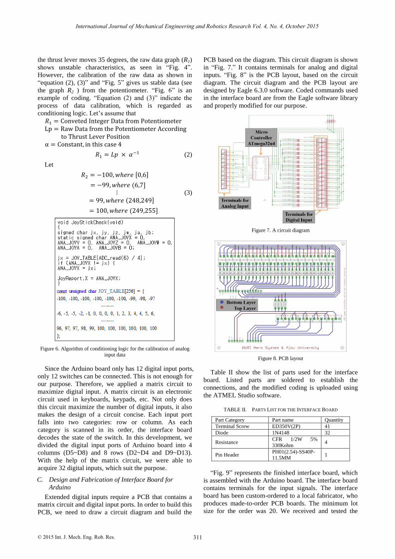
PCB based on the diagram. This circuit diagram is shown
in “Fig. 7.” It contains terminals for analog and digital
inputs. “Fig. 8” is the PCB layout, based on the circuit
diagram. The circuit diagram and the PCB layout are
designed by Eagle 6.3.0 software. Coded commands used
in the interface board are from the Eagle software library
and properly modified for our purpose.
Figure 7. A circuit diagram
Figure 8. PCB layout
Table II show the list of parts used for the interface
board. Listed parts are soldered to establish the
connections, and the modified coding is uploaded using
the ATMEL Studio software.
TABLE II. PARTS LIST FOR THE INTERFACE BOARD
Part Category Part name Quantity
Terminal Screw ED350V(2P) 41
Diode 1N4148 32
Resistance CFR 1/2W 5%
330Kohm 4
Pin Header PH01(2.54)-SS40P-11.5MM
1
“Fig. 9” represents the finished interface board, which
is assembled with the Arduino board. The interface board
contains terminals for the input signals. The interface
board has been custom-ordered to a local fabricator, who
produces made-to-order PCB boards. The minimum lot
size for the order was 20. We received and tested the
311
International Journal of Mechanical Engineering and Robotics Research Vol. 4, No. 4, October 2015
© 2015 Int. J. Mech. Eng. Rob. Res.

delivered interface boards before integration with
Arduino.
Figure 9. Interface board integrated with arduino
D. Verification of Interface Board
Due to the Interface board’s compliance to the HID
Protocols, we can easily verify the work of the interface
board. Our result shows that the 6 analog inputs and 32
digital inputs are working properly. We also verified our
interface board using FSUIPC that provides connections
between hardware and software. It offers numerous data
offsets that user can adjust. We used the FS Interrogate
Function in FSUIPC SDK, to check the workings of the
input signals.
III. INTEGRATION WITH SIMULATOR
The Boeing 747 throttle quadrant is connected to the
simulator with the use of developed interface board and
Arduino. “Fig. 10” shows the development process of the
throttle quadrant. The throttle quadrant model was
created using the Trimble’s Sketchup software. “Fig. 11”
to “Fig. 14” show the 3D modeling of the throttle
quadrant components. In “Fig. 11”, the thrust levers are
fixed to the thrust support panel. The potentiometers
recognize the position of levers. The structure dimensions
are identical to the actual Boeing 747-400. In “Fig. 12”,
the thrust lever has three functions. First is to control the
engine thrust; second is the engine thrust reversal; and
third is the auto-throttle disengage switch. We used
springs to give a tension to the levers. In “Fig. 13”, the
parking break lever has a switch for release. In order to
lock the lever’s position, we designed a groove to hold
the component. In “Fig. 14”, the interface board is
integrated. The speed brake lever is also connected to the
potentiometer.
Figure 10. Development process of throttle quadrant
Figure 11. Thrust lever support panel modeling of throttle quadrant
Figure 12. Parking brake modeling of throttle quadrant
Figure 13. Parking brake modeling of throttle quadrant
Figure 14. Interface board and speed brake modeling of throttle quadrant
IV. CONCLUSION
According to the Korea’s Ministry of Transportation,
the number of passengers flying on a low-cost airline is
increasing significantly. Also, the aviation industry is
growing all over the world. Therefore, the demand for
commercial-grade flight simulators will continue to rise.
Using the developed interface board, the flight
characteristics of simulator shows a good stability in
312
International Journal of Mechanical Engineering and Robotics Research Vol. 4, No. 4, October 2015
© 2015 Int. J. Mech. Eng. Rob. Res.

313
International Journal of Mechanical Engineering and Robotics Research Vol. 4, No. 4, October 2015
© 2015 Int. J. Mech. Eng. Rob. Res.
accordance with the user input signals. The behavior of
the aircraft is now very stable and predictable, due to the
properly conditioned electric signals. This is very
different than the initial behavior, where the aircraft
thrust setting was always unstable and unpredictable.
ACKNOWLEDGMENT
This research was supported by the Basic Science
Research Program through the National Research
Foundation of Korea (NRF) funded by the Ministry of
Education (Grant No. NRF-2013R1A1A2006108).
REFERENCES
[1] G. Williams, K. Lawrence, and R. Weeks, “Modeling and simulation technologies: Reconfigurable flight simulation in
modeling and simulation,” AIAA, Maryland, USA, 2004. [2] Y. Sung, S. Choi, M. Kim, C. Kim, and S. Hoe, “Aviation market
trend & anlysis,” Ministry of Land, Infrastructure and Transport,
ED-34, 2015.
[3] J. Lee, “Design and implementation of USB module for foot switch,” Journal of KIICE, vol. 14, no. 8, pp. 1849-1854, Aug,
2014.
[4] D. Lee, S. Lee, and H. Oh, “Implementation of the aircraft autopilot system simulator based on VOR/DME system,” Journal
of KSAS, vol. 38, pp. 564-569, 2010.
[5] L. Buckwalter, Avionics Training: Systems, Installation and Troubleshooting, Leesburg, VA, USA: Avionics Communication
Inc., 2005.
[6] S. Park, Design of USB Interface, South Korea: Dong Yeok Mechatronics, 2006.
[7] J. Boxall, Arduino Workshop: A Hands-on Introduction with 65
Projects, Inc., San Francisco, CA, USA, 2013. [8] S. Lee, and K. Lim, PCB Design Guide Book, South Korea:
Sehwa Publishing Co., 2008.
[9] M. Kang and K. Shin, Electronic Circuit, South Korea: Hanbit Media, 2011.
[10] Boeing 747-400 Operation Manual, Revision 21, The Boeing Co.,
Seattle, UAS, 2001.
Eunghyun Lee has many years of
engineering experience in industrial engineering. He has conducted research
applied to industrial engineering concepts in
military and simulator. He has a major interest in the fields of simulator, military and UAV.
He has studied his master’s degree at Ajou
University.
Yongjin (James) Kwon has many years of
engineering experience in industrial and
academic settings. He has extensive experience & practical knowledge in current
design, manufacturing and quality control. His
work has been cited a number of times in high profile journals. He is currently a professor in
the Department of Industrial Engineering at
Ajou University. Prior to joining Ajou, he was on the faculty of Drexel University,
Philadelphia, USA.