development of an augmenting navigational …
TRANSCRIPT

DEVELOPMENT OF AN AUGMENTING NAVIGATIONAL COGNITION
SYSTEM
Except where reference is made to the work of others, the work described in this thesis is my own or was done in collaboration with my advisory committee. This thesis does not
include proprietary or classified information.
________________________________________ Ying Yang
Certificate of Approval:
_________________________ _________________________ Hari Narayanan Richard Chapman,Chair Associate Professor Associate Professor Computer Science and Software Computer Science and Software Engineering Engineering _________________________ _________________________ Saad Biaz Stephen L. McFarland Assistant Professor Acting Dean Computer Science and Software Graduate School Engineering

DEVELOPMENT OF AN AUGMENTING NAVIGATIONAL COGNITION
SYSTEM
Ying Yang
A Thesis
Submitted to
the Graduate Faculty of
Auburn University
in Partial Fulfillment of the
Requirements for the
Degree of Master of Science
Auburn, Alabama
December 16, 2005

iii
DEVELOPMENT OF AN AUGUMENTING NAVIGATIONAL COGINITION
SYSTEM
Ying Yang
Permission is granted to Auburn University to make copies of this thesis at its discretion, upon request of individuals or institutions and at their expense. The author reserves all publication rights.
______________________________
Signature of Author
______________________________ Date

iv
THESIS ABSTRACT
DEVELOPMENT OF AN AUGMENTING NAVIGATIONAL COGNITION
SYSTEM
Ying Yang
Master of Science, December 16, 2005 (B.E.,University of Electronic Science and Technology of China, 1998)
94 Typed Pages
Directed by Richard Chapman
Social isolation for persons with cognitive impairments due to aging and/or disease is
common and widespread. Those people who have diseases such as early Alzheimer’s and
dementia tend to forget what they have to do to reach their destination and why they are
going there when they go outside unaccompanied. The purpose of this research is to
develop technical components of one device called Mobility Assistance (MA) for those
persons with cognitive impairments. This MA device can store a pre-defined route and
can also track the navigational route of a person. According to context (standing, running,
walking, in vehicle) and position, the MA can detect likely deviations from the expected
route. The MA device can give the lost user various cues to return to the route. If the user

v
fails to resume the correct route or the user encounters an emergency (for example:
falling down), the MA device can alert a caregiver.
There are three modules in this system: sensor, mobile phone and PC. The sensor module
is composed of an analog accelerometer which provides information such as steps,
distance and movement information, an analog compass which provides direction
information, and a Bluetooth transmitter. The main use of the sensor module is for dead-
reckoning navigation when GPS is unavailable. It is also used to detect context such as
sitting, running, or riding in a vehicle. The mobile phone module can determine any
deviations from a programmed route by using GPS and dead-reckoning navigation. The
mobile phone can also prompt/alert the mobile user and communicate with a remote
caregiver. The PC module can be used for route entry and can download the routes to a
Mobile phone.
In this research we have developed and implemented the following components of the
MA device:
1. System software to receive and store transmitted data from the inertial sensor. 2. System software to receive data from a GPS module.
3. Algorithms for direction determination.
4. Algorithms to interpret the sensed data to compute steps and distance of wearer
traveled.

vi
5. Interaction software, running on a PC, to present the data from PDA-phone
appropriately.
6. Interaction software, running on a PDA-phone, that allows the user to setup
conection between phone and PC.
So far, the communication between sensor and mobile phone and between mobile phone
and PC work well. Furthermore, the analog compass can provide accurate direction
information within a ±2° margin. However, the analog accelerometer still can not
provide accurate step detection and stride length information. Future work will be needed
to address these issues.

vii
ACKNOWLEDGMENTS My work on this research project was made possible by the patience and generosity of
some special people to whom I owe many thanks. I would like to express my gratitude to
my major advisors Dr. Chapman and Dr. Narayanan of the Department of Computer
Science and Software Engineering. Without their guidance and suggestion, this thesis can
not be done. I was also very fortunate to collaborate with Subramanian Nambi who was a
PhD candidate in the Department of Electrical Engineering. I learned much hardware
knowledge from him. I also want to thank Dr. Biaz of the Department of Computer
Science and Software Engineering for reading my thesis. Last, I would like to give a
special thanks to my husband Da Li who gave me enthusiastic supports.

viii
Style manual or journal used :
IEEE Standards Style Manual
Computer software used :
MS Word ______________

ix
LIST OF CONTENTS
LIST OF FIGURES ........................................................................................................... xi LIST OF TABLES............................................................................................................ xii CHAPTER 1. INTRODUCTION .................................................................................. 1
1.1 Purpose................................................................................................................ 1 1.2 Related Work ...................................................................................................... 2 1.3 System Design .................................................................................................. 16
CHAPTER 2. HARDWARE PARTS.......................................................................... 19 2.1 Hardware Components Introduction....................................................................... 19
2.1.1 Motorola 68HC11 CPU ................................................................................... 19 2.1.2 Robson 1655R Analog Compass ..................................................................... 20 2.1.3 ADXL202E Accelerometer ............................................................................. 21 2.1.4 EB500-AHC-IN Bluetooth Transmitter........................................................... 24 2.1.5 Nokia 3650 Phone............................................................................................ 25
2.2 Hardware Connections............................................................................................ 26 2.3 Direction Determination ......................................................................................... 27 2.4 Context Determination............................................................................................ 27
CHAPTER 3. SOFTWARE......................................................................................... 29 3.1 Software System Design Introduction .................................................................... 29 3.2 Technologies Background ...................................................................................... 31
3.2.1 Bluetooth.......................................................................................................... 31 3.2.2 Bluetooth on Symbian OS ............................................................................... 34 3.2.3 GPS .................................................................................................................. 35 3.2.4 Used GPS Sentences ........................................................................................ 38
3.3 Communications ..................................................................................................... 38 3.3.1 Bluetooth.......................................................................................................... 38 3.3.2 TCP/IP Socket.................................................................................................. 42
3.4 Algorithms .............................................................................................................. 44 3.4.1 Analog Compass Algorithm ............................................................................ 44 3.4.2 Accelerometer Algorithm ................................................................................ 49 3.4.3 Steps Algorithm ............................................................................................... 51
3.5 User Interface.......................................................................................................... 57 3.5.1 Server Program (On PC).................................................................................. 57 3.5.2 Client Program (On Phone) ............................................................................. 58
CHAPTER 4. EXPERIMENTAL RESULTS.............................................................. 64 4.1Compass algorithm .................................................................................................. 64 4.2Accelerometer algorithm ......................................................................................... 65

x
4.3 Steps algorithm ....................................................................................................... 67 CHAPTER 5. CONCLUSION AND FUTURE WORK ............................................. 70 BIBLIOGRAPHY............................................................................................................. 73 APPENDIX A................................................................................................................... 81 APPENDIX B ................................................................................................................... 83

xi
LIST OF FIGURES
Figure 1.1 Architecture of WABN [2]................................................................................ 3 Figure 1.2 AMON prototype[3].......................................................................................... 4 Figure 1.3 Activity readings:normal two-axis acceleration data from AMON system[3] . 5 Figure 1.4 Typical system architecture of m-health monitoring systems[8] ...................... 7 Figure 1.5 Block diagram of physiological measuring and monitoring system[20]........... 8 Figure 1.6 General layout for the prototype personal monitoring system[23] ................. 11 Figure 1.7 Bluetooth IMU module.................................................................................... 17 Figure 1.8 System architecture ......................................................................................... 18 Figure 2.1 Robson 1655R analog compass....................................................................... 20 Figure 2.2 Pin configuration of ADL202EB[45].............................................................. 22 Figure 2.3 EB500-AHC-IN Bluetooth Transmitter .......................................................... 24 Figure 2.4 Nokia 3650 phone............................................................................................ 25 Figure 2.5 Earthmate GPS receiver .................................................................................. 26 Figure 2.6 Hardware architecture ..................................................................................... 27 Figure 3.1 Software system design ................................................................................... 31 Figure 3.2 The Bluetooth stack......................................................................................... 32 Figure 3.3 UML sequence diagram of bluetooth communciation .................................... 40 Figure 3.4 UML classes for Bluetooth communication................................................... 41 Figure 3.5 UML classes diagram of TCP/IP socket communication................................ 44 Figure 3.6 Outputs of two channels from 1655R compass............................................... 45 Figure 3.7 Algorithm for getting direction ....................................................................... 48 Figure 3.8 Algorithm for getting distance......................................................................... 51 Figure 3.9 Accelerometer data used in step counting ....................................................... 52 Figure 3.10 Algorithm for getting steps............................................................................ 57 Figure 3.11 User Interface of server side.......................................................................... 58 Figure 3.12 Menus on the phone....................................................................................... 59 Figure 3.13 Setting dialog on the phone ........................................................................... 59 Figure 3.14 Port number editor......................................................................................... 60 Figure 3.15 IP address editor ............................................................................................ 60 Figure 3.16 Phone setting page......................................................................................... 61 Figure 3.17 Setting page resource file .............................................................................. 61 Figure 3.18 Define the properties of port number editor and IP address editor ............... 62 Figure 3.19Display for connection ................................................................................... 63 Figure 4.1 Compass test comparison between ideal values and computed values ........... 64 Figure 4.2 Short distance trip(20 meters) ........................................................................ 68 Figure 4.3 Long distance trip (400 meters)....................................................................... 69

xii
LIST OF TABLES
Table 1.1 Four Basic Sensors and their functions for physiological measuring and monitoring system [20] ............................................................................................... 9
Table 2.1 Specification for 1655R.................................................................................... 21 Table 2.2 Pin function descriptions of ADXL202EB[45] ................................................ 22 Table 2.3 Specification of ADX202E............................................................................... 23 Table 3.1 Parts of reference table .................................................................................... 45 Table 3.2 Acceleration from Ax and Ay........................................................................... 52 Table 3.3 Intermediate table for Figure 3.9 ...................................................................... 54 Table 4.1 Parts of the real time test results ....................................................................... 65 Table 4.2 Result of short distance travel........................................................................... 66 Table 4.3 Result of long distance travel............................................................................ 67 Table 4.4 Comparison of steps from short distance trip ................................................... 68 Table 4.5 Comparison of steps from 400 meters distance trip ......................................... 69

1
CHAPTER 1. INTRODUCTION
1.1 Purpose Social isolation for persons with cognitive impairments due to aging and/or disease is
common and widespread. Conditions such as early Alzheimer’s disease and dementia
(incidence rates of 15 per 1000; projected incidence by 2020 is 7 million Americans)
(Lauter, 1985) impair people’s ability to journey outside their homes to access social and
community resources. For example, some cognitively impaired people often forget their
destination or how to get to their destination. Or when some people with conditions such
as heart disease go outside unaccompanied, emergencies such as falling down can often
happen. These situations are very dangerous for these people [1].
This research is part of a project to develop a Mobility Asistance (MA) device that can
help these people with cognitive impairments. This device can store a pre-defined route
before starting to travel. It can track the navigational route of a person. According to
context (standing, running, walking or in vehicle) and position, this device can detect any
likely deviation from the expected route. This device can also give the lost user various
cues to return to the route. If the user fails to resume the correct route or the user

2
encounters an emergency (for example: falling down), the MA device can alert a
caregiver.
1.2 Related Work Research in this area is widespread. Jovanov[2] introduces the wireless body area
network (WBAN) of intelligent motion sensors. Continuous technological advances in
integrated circuits, wireless communication, and sensors enable the development of
miniature, non-invasive physiological sensors that communicate wirelessly with a
personal server and subsequently through the Internet with a remote emergency, weather
forecast or medical database server; using baseline (medical database), sensor (WBAN)
and environmental (emergency or weather forecast) information, algorithms may result in
patient-specific recommendations. The personal server, running on a PDA or a 3G cell
phone, provides the human-computer interface and communicates with the remote
server(s). Figure 1.1 shows a generalized overview of a multi-tier system architecture; the
lowest level encompasses a set of intelligent physiological sensors; the second level is the
personal server (Internet enabled PDA, cell-phone, or home computer); and the third
level encompasses a network of remote health care servers and related services
(Caregiver, Physician, Clinic, Emergency & Weather etc.). Each level represents a fairly
complex subsystem with a local hierarchy employed to ensure efficiency, portability,
security, and reduced cost.[2].

3
Figure 1.1 Architecture of WABN [2]
The group of Urs Anliker[3] developeded the advanced care and alert portable
telemedical monitor (AMON), a wearable multiparameter medical monitoring and alert
system targeting high-risk cardiac/respiratory patients. The system includes continuous
collection and evaluation of multiple vital signs,intelligent multiparameter medical
emergency detection, and a cellular connection to a telemedicine center(TMC). The idea
is that by using an unobtrusive wrist-worn device,monitoring can be performed without
interfering with the patients’everyday activities and without restricting their mobility.
Thus, people currently confined to the hospital or their homes can lead nomal lives while
knowing that any medical problems will be detected in time and help will be dispatched.
Additionally, physicians are provided with a greater level of information about a patient’s
condition-from a natural setting-thus enabling them to better tailor treatment[3]. Figure
1.2 shows the prototype of AMON.

4
Figure 1.2 AMON prototype[3]
Compared with MA device, several unique features of AMON system are as following:
First, the AMON system is capable of measuring blood pressure,SpO2 , and a one lead
ECG, all in a aingle device. There are currently no handheld or portable device which
combines all of these measurements. Second, The AMON system combines all
sensors,communiction, and processing devices in a single ergonomic wrist-worn
enclosure. Third, the AMON system can perform an analysis of all measurements online,
presenting them in appropriate form to both wearer and remote TMC. For emergency
detection, the analysis can incorporate the patient’s profile and activity information to
reduce the number of false alarms. AMON system has similar features as MA device has.
First, the cellular connection to the TMC features a flexible communication channel that
can use a direct connection as well as short message system(SMS) services. It can also be
easily extended to incorporate a tranmission control protocol(TCP)/Internet protocol(IP)-
based link. Second, using a two-axis acceleration sensor integrated in the system, AMON

5
is capable of detecting the context of user also. The AMON system requires only very
simple activity analysis compared to other wearable activity detection application,e.g.,[4].
Thus, for example eating,drinking, or just talking and gesticulating involve arm motions
that are not paricularly strenuous. AMON device only detected the activity associated
with (fast) walking or running. Figure 1.3 shows the activity reading from
AMON[3].Currently, we can not get accurately to detect context of the wearer of MA
device. See Chapter 4 Experimental Results. So we can learn from AMON system about
how to get correct context information of the wearer.
Figure 1.3 Activity readings:normal two-axis acceleration data from AMON system[3]
M-Health can be defined as “mobile computing,medical sensor, and communications
technologies for health-care.“ This concept represents the evolution of e-health systems
from traditional desktop “telemedicine“ platforms to wireless and mobile

6
configurations[5]. Recently, there are many wireless communication and network
technologies around mobile health systems. For example, development of smart
intelligent sensors and drug delivery devices, some of them implanted, will allow
communication with a personal server in complete mobility[6]. Physicians’access to
patient history, laboratory results, and medical resources would be enhanced by mobile
technology. Handheld devices can be used in home health care. A overview of some
existing applications can be found in recent publictions in the area [7-11].
Currently, many wireless technologies are mainly depending on general packet radio
service(GPRS) technologies. There are some limitations which can be summarized as
following[12]: 1)There are no “m-health protocols“ as linkage of the different mobile
telecommunciation options and standards for e-health services. 2)The high cost of
communication links should be considered, especially between satellites and global
mobile devices. Network security of mobile internet connection and information access
especially for e-health system is another issue. 3)Currently, most physicans and health-
care experts yet do not fully understand these technologies. 4) The software receiving
paymant and reimbursement for m-health services are not fully developed and
standardized. 5) The demostration projects so far failed to show that m-health sevices
result in savings and have cost effective potential. Figure 1.4 shows the concepts of

7
m-health system. It is very similar to Figure 1.1.
Figure 1.4 Typical system architecture of m-health monitoring systems[8]
The typcial application of m-health system includes the following[8]:
1) Wearable systems and personal heath-care mointoring[13],[14];
2) Monitorng of soliders in the battlefield[15];
3) Emergency medical care;
4) Home mointoring [16],[17],[18];
5) Computer-assisted rehabilitation and therapy[19];
6) Social networking of relatives and peers of chronically ill patients.

8
Fazlur Rahmn, Arun Kumar, Gangadharan Nagendra and Gourab Sen Gupta describe a
system called physiological measuring and monitoring system (PMMS) which is able to
record physiological parameters such as height,weight,body temperature,heart rate,and
blood oxygen saturation level of a person[20]. A block diagram of the PMMS is shown in
Figure 1.5. The system meaures and mointors the physiological parameters gathered from
different type of sensors used for the purposed listed in Table 1.1.
Figure 1.5 Block diagram of physiological measuring and monitoring system[20]
9
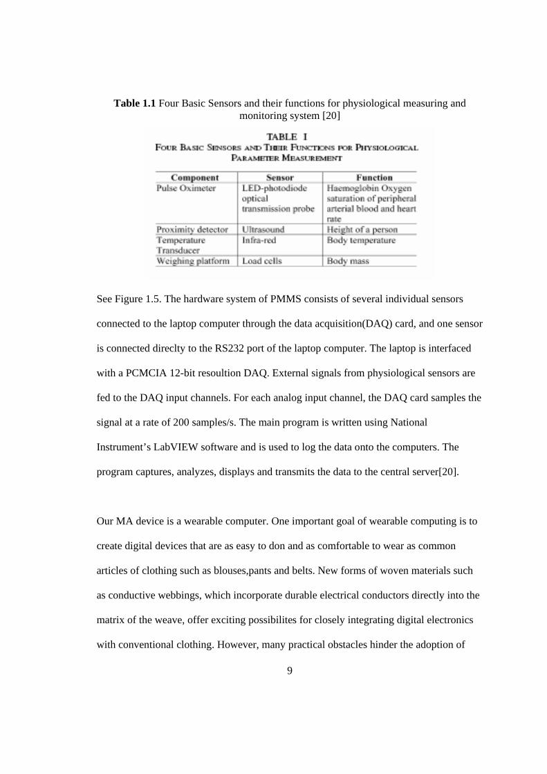
Table 1.1 Four Basic Sensors and their functions for physiological measuring and monitoring system [20]
See Figure 1.5. The hardware system of PMMS consists of several individual sensors
connected to the laptop computer through the data acquisition(DAQ) card, and one sensor
is connected direclty to the RS232 port of the laptop computer. The laptop is interfaced
with a PCMCIA 12-bit resoultion DAQ. External signals from physiological sensors are
fed to the DAQ input channels. For each analog input channel, the DAQ card samples the
signal at a rate of 200 samples/s. The main program is written using National
Instrument’s LabVIEW software and is used to log the data onto the computers. The
program captures, analyzes, displays and transmits the data to the central server[20].
Our MA device is a wearable computer. One important goal of wearable computing is to
create digital devices that are as easy to don and as comfortable to wear as common
articles of clothing such as blouses,pants and belts. New forms of woven materials such
as conductive webbings, which incorporate durable electrical conductors directly into the
matrix of the weave, offer exciting possibilites for closely integrating digital electronics
with conventional clothing. However, many practical obstacles hinder the adoption of

10
these materials, not the least being a lack of reliable electrical connectors for the
interconnection of conventional electronics with conductive fabrics[21]. Michael
M.Gorlick presents a simple and workable design for just such connectors and demostrate
how a commonplace article of clothing-suspenders can be transformed into an effective
power bus and data network for wearable digital devices[21].
An implementation of an unobstusive five-point acceleration sensing wireless body area
network(WBAN) with mobile device data logging capabilities is presented, along with
practical experiences on performance[22]. The tested device is a small, matchbox size
device with sensing and communications capabilities,thus it is unobtrusive for measuring
use activity. The basic board holds a realtime clock circuit, which provides timing
reference precise enough for implementing a TDMA based MAC protocol. The
Microchip PIC16LF877 is used as a mcirocontroller. RS-232 is used for serial
communications with external devices. A single channel, 1mW license free radio (RF
Monolithics TR 1001) is used for networking devices, providing 10 kbps bidirectional,
half duplex wireless communciations. The standard sensor board of SoapBox ver. 1.0
includes five different types of sensors. Only the 3-axis acceleration sensor(two ±2g
Analog Devices ADXL202JE) is utilized in the WBAN arrangement. In one node, a±10g
derivative of the sensor is used. The test results show good communications performance
in laboratory conditions. But field test performance is weak[22].
G.Edward Barnes and Steve Warren proposed “A wearable, bluetooth-enabled system for
home health care“[23]. The portable personal monitoring system was designed to

11
incorporate three devices that communicate wirelessly using Bluetooth. The device
consists of the base station, data logger, and sensor unit. The monitoring system can have
multiple sensor units that acquire physiological data from an individual. The system has a
central control and storage component, called the data logger, to which all of the sensors
on the piconet are connected. Finally, a connection to the network, called the base station,
allows communication between the portable system and the outside world. This network
access allows for processing, further data storage(e.g. in a patient’s electronic medical
record), and physician access to data. The prototype demonstrates that data can be taken
by the remote sensor, stored and sent to the coordinating data logger, while the data
logger can receive and store data from the sensor unit, control the sensor unit, and send
data to the base station to be displayed[23]. Figure 1.6 depicts the layout for the personal
monitoring system.
Figure 1.6 General layout for the prototype personal monitoring system[23]
Matthew B. Lau proposed a system called “The Snap!“ in his master’s thesis[24]. The
Snap! is a cross-contry ski system which was designed to measure information about the

12
interaction between a skier and a pair of skis. The goal of The Snap! is to correlate
information about the skier(heart rate, GPS location, and local air temperature & pressure)
and information about the ski equipment(boot flex, toe angle, heel pressure, etc.). The
Snap! network was constructed with sensors on booth boots, both skis, and in the skiers
backpack. Here, I want to mention that the author puts sensors on left and right skies to
get toe angle, three axis acceleration and compass information. On the ski, two analog
devices ADXL210[25] 10g, two-axis accelerometers were mounted perpendicular to one
another to detect acceleration along three orthogonal axes. A Precision Navigaion Vector
2x[26] compass was mounted atop each ski to detect direction. These parts are capable of
measuring acceleration small enough to show small degrees of tilt in the ski, and as large
(±)10 g. The acceleration and boot angle are configured to measure at 20 Hz for 3.75
seconds out of every 30. The accelerometer module on the left ski was programmed to
send out configuration packets to the other transducers to synchronize measurements
across both skies. The compass sensor reported a single measurement every half minute.
The x-axis of acceleration is in the direction of the ski. The y-axis shows lateral motion in
the horizontal plane (side-to-side along the surface of the earth), and z-axis measures in
vertical direction(with the positive-z direction measuring downward acceleration)[24].
A portable physical rehabiltation monitoring system based on a personal network of
intelligent sensors is described in [27]. Rehabilitation is traditionally carried out in
hospitals under the supervision of qualified personnel. So, using a PDA which can offfer
large processing power, decent graphical user interface and compact flash based
secondary memory can be helpful. Individual sensors are positioned on limbs to analyze

13
movement using 2-axis MEMS accelerometers[28]. The system generates real-time
warnings when predefined thresholds have been exceeded.The system also can be put on
the hip and knee[27].
Jack M,Winters, Yu Wang, and Jill M. Winters write the paper which summarizes
ongoing research on both mobile interfaces and therapies related to rehabilitation. They
design a system called the mobile intelligent telerehabilitation assistant(ITA) which is a
long-term project intended to provide an alternative for 21st-century rehabilitative
telecare. The interactive, mobile ITA interfaces and telecommunications infrastructure
are desribed[29].
In the MA system, a GPS receiver is used to locate a position outdoors. But an indoor
position is also needed in our system. We use dead reckoning(DR) to estimate the
position indoors or at locations where a GPS can not receive a signal from satellites.
Dead reckoning is the process of estimating the current position by advancing a known
previous position using course, speed, time and distance to be traveled. This is not only a
domain for the humans, but also for primative animals like ants who do dead reckoning
as well[30].The history of DR began with terrestrial or nautical navigation. Nowdays DR
is needed to navigate outdoor and indoor positions. With much efforte the PointMan™
Dead Reckoning Module (DRM™) has been developed. This is a miniature, self-
contained, electronic navigation unit that provides the user’s position(Latitude/Longitude)
relative to an initialization point obtained by some other method. The PointMan™
DRM™ is the first practical implementation of a drift-free dead reckoning navigation

14
system for use by personnel on foot. It is specifically designed to supplement GPS
receivers during signal outages. It even works inside of many buildings but does not
support a varying step length[31]. A recent solution for accurate navigation is the use of
sensorfusion techniques to combine different sensor types to improve the performance of
the navigation systems[32]. Military research centers are also implementing remarkable
solutions[33].
In our MA devices, an acceleration algorithm is designed to get distance the wearer
travels. Steps and strides of every step is computed from 2-axis ADXL202EB
acclerometer data. Then, the distance is computed by adding all strides together. See
Section 3.4.2 Acclerometer Algorithm. Fyfe[35] and Sagawa [36] proposed similar ideas.
The motion analysis sy`stem patented by Fyfe [35] in 1999 applies a biaxial sagittal
plane accelerometer to measure foot acceleration. A third parallel offset accelerometer
is used to allow measurement of angular acceleration which is integrated twice to yield
the foot angle profile for the stride. The foot angle profile is then used to resolve the
horizontal acceleration from the biaxial accelerometer measurements, and this horizontal
acceleration is integrated twice to yield stride length. Drift is reduced by making use of
the zero velocity reference during stance phase and removing the signal mean prior to
integration. Accurate to within 3% over a wide population and without user calibration,
this technique is valid for a complete range of gait velocities from slow walk to full run
and has been applied in related consumer products such as the Nike SDM[34].

15
Sagawa [36] demonstrated a similar system in 2000 that applies a triad of accelerometers
and a sagittal plane gyro. While the gyro requires only a single integration to measure the
foot angle profile, this technique is otherwise functionally identical to Fyfe. Over
multiple 30 m trials, this method had a maximum error of 5%[34].
As with some of the stride modelling techniques, the work by Sagawa and Fyfe relies
on the assumption that the foot motion is primarily in the sagittal plane. However, these
methods have a possible advantage in that they measure step length directly and work
without making further assumptions about the user’s height, gait, or walking environment.
From a practical perspective, Fyfe’s entirely accelerometer based method may be
preferred to Sagawa’s as accelerometers are currently less expensive, smaller, draw less
power and drift less than gyros[34].
In Ross Grote Stirling’s thesis[34], a pedestrian dead reckoning system is proposed that
applies sensors mounted on the shoe.The technique of stride length measurement using
shoe mounted accelerometers invented by Fyfe[35] is applied and analyzed. To get
heading infomation, the magneto-resistive sensors are used. After treadmill tests and field
trials, it was found that it is possible to navigate using shoe mounted sensors though the
overall accuracy does not compare well at this point with conventional methods of
pedestrian navigation and satellite positioning[34].
Making devices aware of the activity of the user fits into the bigger framework of context
awareness, which also aims at awareness of environment and the state of the device

16
itself[37]. Dey and Abowd[38] provided a survey of context and contextaware
applications with handheld and ubiquitous computing requirements in mind:“Context is
any information that can be used to characterize the situation of an entity. An entity is a
person,place, or object that is considered relevant to the interaction between a user and an
appplication, including the user and applications themselves[38].In order to get as much
information on a context as possible, it is necessary to use a large number of different
sensors. All of the raw sensor values would be used as inputs for the machine learning
algorithms.Kristof Van Laerhoven and Ozan Cakmakci describe a combination of
machine learning techniques such as Kohonen maps[39] and probabilistic models[37].
There are many algoirthms for predicting location and orientation as well. A.Elnagar and
A.M.Hussein describe an algorithm for predicting future positions and orientation of a
moving object in a time-varying environment using an autoregressive model(ARM)[40].
Yu.P.Grishin presents the structure and algorithms of fault-tolerant date processing in an
integrated GPS-based airborne navigational equipment intended for enhancing the
integrity of the whole navigational system[41].
1.3 System Design There are three basic modules in the MA system. They are the sensor module, mobile
phone module and PC module. The sensor module is composed of a Bluetooth
transmitting device, an analog compass and an accelerometer. The analog compass
provides direction information. The accelerometer provides steps, distance, and
movement situation information. Figure 1.7 shows the sensor module architecture.

17
Figure 1.7 Bluetooth IMU module
The sensor module is used for dead-reckoning navigation when GPS is unavailable. It is
also used to detect context such as sitting, running or riding in vehicle. The mobile phone
module can detect context based on sensor data. It also is used to determine deviation
from a programmed route using GPS and dead-reckoning navigation. The mobile phone
module can cause the user interface to prompt/alert the mobile user. If the user needs
more help, the mobile phone module will communicate with a related caregiver. The PC
module permits route entry, and it can download a route to a mobile device. Figure 1.8
depicts the whole system’s architecture.

18
network
Computer
Bluetooth GPS
Bluetooth IMU
Wireless gateway
System Architecture
Figure 1.8 System architecture
Chapter 2 describes hardware setup and Chapter 3 is about the software implementation
of the entire system. Chapter 4 analyzes the experimental results. Chapter 5 gives the
conclusion and describes future work.

19
CHAPTER 2. HARDWARE PARTS
In this chapter, the specifications and application hardware setup details are described.
Accelerometers, analog compass, and microprocessor are used in this MA system. Some
positional reference equipment such as the GPS receiver is also described. Finally, since
the evaluation of this method of pedestrian navigation depends on the quality of the data
from the sensor, the experimental data is reviewed.
2.1 Hardware Components Introduction
2.1.1 Motorola 68HC11 CPU
The MC68HC11 is an advanced 8-bit MCU with highly sophisticated, on-chip peripheral
capabilities. It can achieve a nominal bus speed of 2MHZ. On-chip memory systems
include 8 Kbytes of read-only memory(ROM), 512 bytes of electrically erasable
programmable ROM, and 256 bytes of random-access memory.
Major peripheral functions are provided on-chip. An eight-channel analog-to-digital (A/D)
converter is included with eight bits of resolution. An asynchronous serial
communications interface (SCI) and a separate synchronous serial peripheral interface
(SPI) are included. The main 16-bit, free-running timer system has three input-capture

20
lines, five output-compare lines, and a real-time interrupt function. An 8-bit pulse
accumulator subsystem can count external events or measure external periods. A
watchdog system protects against software failures. A clock monitor system generates a
system reset in case the clock is lost or runs too slow[44].
2.1.2 Robson 1655R Analog Compass
The R1655 analog compass sensor made by the robson company,INC. (see Figure 2.1)
requires a closely regulated 5.00 volts DC input and produces a ratiometric DC output.
The input should be “spike” and polarity protected if operated from a vehicle power
supply. The output closely resembles two channels of a sine-cosine set of curves which
cross at approximately 2.5 volts and peak at approximately 3.1 volts and floor at about
1.9 volts. Each output will drive up to 4 mA.
Figure 2.1 Robson 1655R analog compass

21
Table 2.1 shows specifications for the 1655 Analog compass.
Table 2.1 Specification for 1655R
Power 5-volts DC @ 19 ma. Since rise time is only 90
nanoseconds, input current may be pulsed to save
power.
Outputs Dual analog channels, 2.5v ?0.75v swing (total voltage
swing rail to rail, aprox. 1.50v), 4ma DC signal. May
feed direct to A-D front end of microprocessor.
Weight 2.25 grams
Size 12.7 mm diameter, 16 mm tall
Pins 3 pins on 2 sides on .050 centers
Temp -20 to +85 degrees C
2.1.3 ADXL202E Accelerometer
ADXL202E was chosen for acceleration measurement because of its compact size, robust
design, low-cost and low-power. It can measure both dynamic acceleration (e.g.,
vibration) and static acceleration (e.g., gravity).
The outputs of ADXL202E are Duty Cycle Modulated (DCM) signals whose duty cycles
(ratio of pulse width to period) are proportional to the acceleration in each of the 2
sensitive axes. These outputs may be measured directly with a microprocessor counter,
requiring no A/D converter or glue logic. The DCM period is adjustable from 0.5ms to 10

22
ms via a single resistor (Rset). If an analog output is desired, an analog output
proportional to acceleration is available from the XFILT and YFILT pins (see Figure 2.2
and Table 2.2) or may be reconstructed by filtering the duty cycle outputs.
Figure 2.2 Pin configuration of ADL202EB[45]
Table 2.2 Pin function descriptions of ADXL202EB[45]
The bandwidth of the ADXL202E maybe set from 0.01Hz to 6 kHz via capacitors Cx and
Cy. The typical noise floor is 100µg√Hz allowing signals below 2mg to be resolved for
bandwidths below 60Hz.

23
Table 2.3 shows the specification of ADXL202E.
Table 2.3 Specification of ADX202E
Parameters ADXL202E
# Axis 2
Range +/- 2g
Sensitivity 12.5 %/g
Sensitivity Accuracy ±16
Output Type PWM
Bandwidth 6kHz
Noise Density 200
Supply Voltage 3 to 5.25
Supply Current 0.6mA
Temp Range -40 to 85°C
Package E-8
Functionally, the ADXL202E is simple to use. Supply voltage of 3 to 5V is sufficient to
power the chip, but since the analog output of the sensors is proportional to the supply
voltage, 5V was used to maximize sensitivity. Capacitors placed on the output pins are
used to limit the sensor bandwidth and reduce noise. In this application, the output was
band-limited to 10-20 Hz, and the power supply was 5V.

24
2.1.4 EB500-AHC-IN Bluetooth Transmitter
Figure 2.3 EB500-AHC-IN Bluetooth Transmitter
The communication between the Nokia 3650 and the Motorola 68HC11 is done by
Bluetooth. We selected to use the EB500 Bluetooth Radio Module to connect with the
Motorola 68HC11. The embedded blue Series EB500 Bluetooth radio module is ideal for
enabling the Motorola 68HC11 with a widely supported industry standard wireless
protocol. Monitoring and control applications will benefit from an integrated
implementation of the serial port profile for seamless connectivity with PDA phones. Its
low current consumption makes the EB500 ideal for use in standalone battery powered
devices such as the Sensor model of this application.
The EB500 implements all components of the Bluetooth stack on board so that additional
host processor code is not required. Once a connection to another Bluetooth device has
been established, the link has the appearance of a cabled serial connection eliminating the
need for special wireless protocol knowledge.
Simple UART communication facilitates the interface between the host processor and the
Series EB500 radio. This UART interface may be used to discover, connect, and

25
communicate with other Bluetooth devices. A LED indicator for connection status is
provided.
2.1.5 Nokia 3650 Phone
Figure 2.4 Nokia 3650 phone
The Nokia 3650 phone is a mobile phone with PDA features. It has a big LCD screen
(176x208 pixels), as well as support for infrared and Bluetooth wireless connectivity.
This phone can combine picture, video, text and voice clips and send them by MMS or
email to a compatible phone or PC. It can also send email over GSM data, HSCSD, and
GPRS. In this system, we need real time connections between phone and PC. So a data
transfer feature is necessary. The Nokia 3650 supports up to 43.2 kilobits per second in
high-speed circuit switched data networks and up to 40.2 kilobits per second in GPRS
networks. From a software development perspective, this phone supports J2ME MIDP
1.0 and can download new Java games and applications. It also has support for the
Symbian 60 platform. The Symbian SDK 6.0 can be downloaded for free from the Nokia
website.

26
2.1.6 Bluetooth GPS
Figure 2.5 Earthmate GPS receiver
The Earthmate GPS can be used for in-vehicle tracking purposes and also as a stationary
sub-meter positioning device. With the Delorme Bluetooth PowerPack, the data can be
transmitted to a laptop or Bluetooth-capable handheld computer. Messages from this
device are complied with an NEMA 0183 v2.0 output standard. This device sends an
NEMA message such as GGA,GSA,GSV,RMC For details of the message, see section
3.2.3 GPS parts.
2.2 Hardware Connections
Figure 2.6 shows the hardware architecture. The whole hardware is composed of an
analog compass, an accelerometer ADXL202E, a 68HC11 microprocessor, and an EB500
Bluetooth Transmitter. The analog compass sends data to the 68HC11, and the
ADXL202E sends sensor data to the 68HC11. A program is used to combine them
together and the 68HC11 sends both of them to the phone over Bluetooth.

27
Figure 2.6 Hardware architecture
2.3 Direction Determination
We select the sensor called the R1655 Analog sensor from the Dinsmore Instrument
Company to provide direction information. The sensor is connected with the 68HC11 as
shown in Figure 2.6. Raw data are sent to the Nokia 3650 over Bluetooth. The algorithm
program for direction determination is running on the phone. See Software Parts, Chapter
3 for details of the algorithm.
2.4 Context Determination
Context in this application is any information that can be used to characterize the
situation of a person such as walking, running, standing still or riding on a vehicle. The
accelerometer ADXL202E is selected to get the acceleration to detect the context of a
wearer. The ADXL202E is connected with the 68HC11. The Motorola 68HC11 sends

28
raw data to the Nokia 3650; the context recognition algorithm running on the phone will
detect current context of the person. Currently, in order to detect correct context
information, the ADXL202E is put on the hip of the person. For more information about
the accelerometer algorithm mentioned here, see Software Parts, Chapter 3.

29
CHAPTER 3. SOFTWARE In this chapter, software implementation is discussed. That includes the communication
over Bluetooth between the Earth-mate GPS device and the Nokia 3650, the
communication over Bluetooth between the Motorola 68HC11 and the Nokia 3650, the
communication between the Nokia 3650 and the PC with a TCP/IP socket. The compass
algorithm and accelerometer algorithm will also be discussed. The implementation GUI
for the Nokia 3650 and server side program running on the PC to display data such as
latitude/longitude, compass degree and distances is described in this chapter as well.
3.1 Software System Design Introduction
The entire software system falls into three categories: user interface(UI), communication
and algorithms. Figure 3.1 shows the relationship between the three categories.
On the Nokia 3650, the UI consists of a TCP/IP setting dialog, a Bluetooth discovery
dialog and a real-time data display list. The IP address and port number of the PC can be
set in the TCP/IP setting dialog, and the Bluetooth discovery dialog is designed to display
all of the Bluetooth devices in range. On the PC, a UI program is written in Java. The UI

30
will display data transmitted from the Nokia 3650, such as latitude/longtitude, compass
degree and distances etc.
Between the Nokia 3650 and the PC the communication is over a TCP/IP socket (using
T-Mobile’s T-Zone wireless data service). And the Motorola 68HC11 communicates
with the Nokia 3650 by using Bluetooth.
Algorithms play an important role in this system. In order to get correct direction
information, one compass algorithm was developed to handle raw data from the Robson
1655R compass. Another algorithm is for the accerometer, and it has two functions: one
is to get the correct context information of the user and another one is to get the position
information for the indoors, where GPS data is usually unavaliable.

31
Figure 3.1 Software system design
3.2 Technologies Background
3.2.1 Bluetooth
Bluetooth is a short-range communication technology, standardized by the Bluetooth
Special Interest Group (SIG).
The Bluetooth Stack is shown as below (Figure 3.2):

32
Figure 3.2 The Bluetooth stack

33
The Bluetooth Host Controller components provide the lower-level of the stack. It is
typically implemented in hardware.
The Bluetooth Host components allow an application to send or receive data over a
Bluetooth link, or to configure the link. It theoretically contains the following layers:
RFCOMM: allows an application to treat a Bluetooth link in a similar way as if it
were communicating over a serial port.
Logical Link Control and Adaptation Protocol (L2CAP): allows finer-grained
control of the link. It controls how multiple users of the link are multiplexed
together, handles packet segmentation and reassembly, and conveys quality of
service information.
Service Discovery Protocol (SDP): used for locating and describing services
provided by or available through a Bluetooth device. Applications typically use it
when they are setting up communications to another Bluetooth device.
Host Controller Interface (HCI) driver: packages the higher level components to
communicate with the hardware.
34
3.2.2 Bluetooth on Symbian OS
The Symbian OS has a Bluetooth stack that is fully compliant with Bluetooth v1.1
specifications. The services that a Bluetooth implementation can offer are characterized
by the Bluetooth standards as a number of profiles. The Symbian OS Bluetooth stack
fully implements the Generic Access Profile, the Serial Port Profile and the General
Object Exchange Profile. All other Bluetooth profiles are dependent on these three core
profiles.
The Symbian OS implementation of this stack is made up of a Bluetooth Sockets module,
Bluetooth Service Discovery Database, Bluetooth Service Discovery Agent, Bluetooth
Security Manager and Bluetooth UI Module. Bluetooth Sockets encapsulates access to
L2CAP and RFCOMM through a TCP/IP-like sockets interface. Bluetooth Service
Discovery Database encapsulates one side of SDP: a local service uses it to record its
attributes, so that remote devices may discover its presence, and determine if it is
appropriate to use. Bluetooth Service Discovery Agent encapsulates the other side of
SDP: it allows one to discover the services that are available on a remote device, and the
attributes of those services. Bluetooth security manager enables services to set
appropriate security requirements that the incoming connections must meet. Bluetooth UI
provides an API by which a dialog can be called that asks users for device selection
information.

35
3.2.3 GPS
Global Positioning System (GPS) is a system of satellites and receiving devices used to
compute positions on the Earth. GPS is used in navigation.
The National Marine Electronics Association (NMEA) is a standard protocol used by
GPS receivers to transmit data. NMEA output is EIA-422A, but for most purposes, we
can consider that it is RS-232 compatible. It uses 4800 bps, 8data bits, no parity and one
stop bit. NEMA 0183 sentences are all ASCII. Each sentence begins with a dollar sign ($)
and ends with a carriage return linefeed(<CR><LF>). Data is comma delimited. All
commas must be included as they act as markers. Following the $ is the address field
"aaccc". "aa" is the device id. For example, GP is used to identify GPS data. "ccc" is the
sentence formatter, otherwise known as the sentence name[42]. The GPS device used in
my research project is called the Earthmate GPS receiver. The Earthmate GPS’s output is
complied by NEMA 0183 v2.0 output standard. This device sends NEMA messages
GGA,GSA,GSV and RMC whose formats are given as following:
$GPGGA,hhmmss.ss,llll.ll,a,yyyyy.yy,a,x,xx,x.x,x.x,M,x.x,M,x.x,xxxx*hh
GGA = Global Positioning System Fix Data
1 = UTC of Position
2 = Latitude
3 = N or S
4 = Longitude

36
5 = E or W
6 = GPS quality indicator (0=invalid; 1=GPS fix; 2=Diff. GPS fix)
7 = Number of satellites in use [not those in view]
8 = Horizontal dilution of position
9 = Antenna altitude above/below mean sea level (geoid)
10 = Meters (Antenna height unit)
11 = Geoidal separation (Diff. between WGS-84 earth ellipsoid and
mean sea level. -=geoid is below WGS-84 ellipsoid)
12 = Meters (Units of geoidal separation)
13 = Age in seconds since last update from diff. reference station
14 = Diff. reference station ID#
15 = Checksum
$GPGSA,A,3,19,28,14,18,27,22,31,39,,,,,1.7,1.0,1.3*35
GSA = GPS receiver operating mode, SVs used for navigation, and DOP values.
1 = Mode:
M=Manual, forced to operate in 2D or 3D
A=Automatic, 3D/2D
2 = Mode:
1=Fix not available
2=2D
3=3D
3-14 = IDs of SVs used in position fix (null for unused fields)

37
15 = PDOP
16 = HDOP
17 = VDOP
$GPGSV,4,1,13,02,02,213,,03,-3,000,,11,00,121,,14,13,172,05*67
GSV = Number of SVs in view, PRN numbers, elevation, azimuth & SNR values.
1 = Total number of messages of this type in this cycle
2 = Message number
3 = Total number of SVs in view
4 = SV PRN number
5 = Elevation in degrees, 90 maximum
6 = Azimuth, degrees from true north, 000 to 359
7 = SNR, 00-99 dB (null when not tracking)
8-11 = Information about second SV, same as field 4-7
12-15= Information about third SV, same as field 4-7
16-19= Information about fourth SV, same as field 4-7
$GPRMC,hhmmss.ss,A,llll.ll,a,yyyyy.yy,a,x.x,x.x,ddmmyy,x.x,a*hh
RMC = Recommended Minimum Specific GPS/TRANSIT Data
1 = UTC of position fix
2 = Data status (V=navigation receiver warning)
3 = Latitude of fix
4 = N or S

38
5 = Longitude of fix
6 = E or W
7 = Speed over ground in knots
8 = Track made good in degrees True
9 = UT date
10 = Magnetic variation degrees (Easterly var. subtracts from true course)
11 = E or W
12 = Checksum
3.2.4 Used GPS Sentences
In this project, only the latitude and longitude information which is contained in the GGA
messages from the Earthmate Bluetooth GPS receiver are considered. This kind of
information can be further passed into certain MAP SDK software running on a PC. And
the MAP SDK can return address information to the Nokia 3650. If other positioning
information is needed, other formats of messages may be considered.
3.3 Communications
This section will decribe all of the communications between the Motorola 68HC11 and
the Nokia 3650, and the communciations between the PC and the Nokia 3650.
3.3.1 Bluetooth
3.3.1.1 Introduction of Use-cases

39
This section gives an overview of the interaction between the user, the Nokia 3650, and
the GPS receiver/Motorola 68HC11 when the phone receives messages from GPS
receiver or Motorola 68HC11. Figure 3.3, UML sequence diagram below, shows the
interactions. The user powers on the Motorola 68HC11 with the EB500 or the GPS
receiver. The devices will initialize the Bluetooth serial port service and advertise the
service by adding an appropriate record to the SDP database. Then the user selects the
“Discover“ menu on the Nokia 3650. The Nokia 3650 then displays a list of Bluetooth
devices in range. The user selects one device (server device) from the list. The Nokia
3650 queries the SDP database to check that it is advertising the Serial Port service, and
to extract necessary parameters of that service. Then the Nokia 3650 requests a serial port
connection with the GPS/68HC11 over the Bluetooth. The Server bluetooth device
informs the Nokia 3650 that the connection has been accepted. At the same time, the
Nokia 3650 starts receiving message from the GPS or the 68HC11. After receiving
messages, the Nokia 3650 handles these messages using the algorithms then displays the
result to the user.

40
Figure 3.3 UML sequence diagram of bluetooth communciation
3.3.1.2 Design and implementation
Figure 3.4 shows the classes structure of the objects how to receive message from the
GPS receiver or the 68HC11 over the Bluetooth.

41
Figure 3.4 UML classes for Bluetooth communication
Class CBTPointToPontAppUI is the user interface class. It uses an object of
CMessageClient to connect to another device and receive messages from remote devices.
This class object uses the Symbian OS classes, RsocketServ and RSocket to open a
socket to the GPS Receiver/68HC11. Before it opens the socket, the CmessageClient
object needs to discover the Bluetooth device in its range and queries its SDP to find
parameters relating to the Serial Port service. The Symbain OS class Rnotifier is used to
discover the device. CmessageClient uses an instance of CmessageServcieSearch to

42
query the server-side device’s SDP database and extract the port number to use for Serial
Port service.
The CmessageServiceSearch class is derived from a general service searching object
CBTService Searcher which connects to the server-side device’s SDP database. Class
CsdpAgent can make Bluetooth SDP requests to another device. MsdpAgentNotifier
handles responses to Bluetooth SDP queries. CBTServiceSearch uses
TsdpAttributeParser to parse the SDP records. TsdpAttributeParser uses
MsdpAttributeNotifier to notify CBTServiceSearch when it has found a specific value in
an attribute.
3.3.2 TCP/IP Socket
3.3.2.1 TCP/IP Socket on Symbain OS The Symbian OS provides TCP/IP communication services in conjunction with the
Sockets Client API. The Sockets Sever defines a generic interface for all socket type
communication services and defines a plug-in architecture for implementing particular
providers. TCP/IP is such a plug-in. Clients access its services through the generic
Sockets Client API, specifying protocol-specific behavior through TCP/IP specific utility
types and constants. The API has three key concepts: TCP/IP socket, domain name
resolver and internet address.
TCP/IP socket: TCP/IP offers IP, ICMP, TCP, and UDP soket types. Socket
services are provided through the generic interface RSocket.

43
Domain Name resolver: Client programs make DNS queries through the generic
host name resolution interface RhostResolver.
Internet address: A socket address, IP address and port, is encapsulated in a
TInetAddr object.
3.3.2.2 Design and Implementation The UML diagram below depicts the classes of the TCP/IP socket commnuication. It
makes use of the following three Symbian OS classes from the Sockets Client API:
RsocketServ: This is used to create a session with the socket server that is
providing a channel of communication with the socket server.
RSocket: Each distinct connection to a remote server requires a RSocket
subsession.
RhostResolver: This can provide name resolution services.
And the core classes are as following:
CsocketsEngine: This class creates the session with the socket server. It also
creates and connects the socket to be used in communication with the server. This
class can handle any feedback from the soket reader(CsocketsReader) and
writer(CsocketsWriter). And reports any change in status and transfer status
messages to the UI for display.
CsocketsReader: This class is used to issue read request to the socket server. It
reports any received data or error to the engine via the MEngineNotifer interface.

44
CsocketsWriter: This class is used to issue a write request to the socket server. It
reprots any errors to the engine via the MEngineNotifer interface.
The following figure 3.5 is the class diagram of the TCP/IP socket program of this
application.
Figure 3.5 UML classes diagram of TCP/IP socket communication
3.4 Algorithms
3.4.1 Analog Compass Algorithm

45
A 1655R Analog compass output closely resembles a sine-cosine set of curves which
cross at approximately 2.5 volts and peak at approximately 3.1 volts and floor at about
1.9 volts. Each output will drive up to 4mA. Figure 3.6 shows the two channels value
after using an 8bits A/D converter. Samples are recorded every 5 degrees.
Channel output v/s Angle
0
50
100
150
200
250
0 25 50 75 100
125
150
175
200
225
250
275
300
325
350
Angle
Dec
imal
val
ue fr
om c
hann
els
Channel1Channel2
Figure 3.6 Outputs of two channels from 1655R compass
Table 3.1 Parts of reference table

46
Index Degree Channel1 Channel20 0 206 2061 5 201 2112 10 196 2153 15 189 2194 20 182 2225 25 175 2246 30 169 2257 35 163 2268 40 154 2279 45 146 227
10 50 139 22711 55 134 22612 60 127 22513 65 116 22414 70 110 223
Table 3.1 is parts of the reference table. The whole table is attached in the Appendix A.
This table is used in compass algorithm. The values in this table are tested by manually
rotating the compass every 5 degrees.
Figure 3.7 shows how the Compass Algorithm works.
Input of algorithm is value1 which is from Channel 1 and value2 which is from Channel 2. Output of algorithm is degree. if ((ch1[0] –sigma) <value1<(ch1[0] + sigma)) && ((ch1[0] –sigma) <value2<(ch1[0] + sigma)) degree = 0 or degree = 360; if ((ch1[37] –sigma) <value1<(ch1[37] + sigma)) && ((ch1[37] –sigma) <value2<(ch1[37] + sigma)) degree = 180; if (value1 < value 2)

47
{ ch1Found = searchIndex(channel1,0,numSamples/2,value1,ch1Indexes); ch2Found = searchIndex(channel2,0,numSamples/2,value2,ch2Indexes); } else { ch1Found = searchIndex(channel1,numSamples/2,numSamples,value1,ch1Indexes); ch2Found = searchIndex(channel2,numSamples/2,numSamples,value2,ch2Indexes); } if (ch1Found >0) && (ch2Found >0) { //Get maxim value of all slots in channel1 ch1Slot = abs( channel1[ch1Indexes[i]] - channel1[ch1Indexes[i+1]]); //Get maxim value of all slots in channel2 ch2Slot = abs( channel2[ch2Indexes[i]] – channel2[ch2Indexes[i+1]]); } if(ch1Found < ch2Found) //normally, the smaller number is used to calculate { return interpolate(ch1Indexes,…) //use channel1 to calculate degree } else { return interpolate(ch2Indexes,…)//use channel2 to calculate degree. } //following is bad data correction, normally bit slot is used to calculate degree. if (ch1Slot >= ch2Slot) { return interpolate(ch1Indexes,…); } else { return interpolate(ch2Indexes,…); } if (ch1Found >0 && ch2Found <=0) // ch2 Data is not correct. { calculate biggest ch1Slot; use ch1 to calculate degree; }

48
if (ch2Found >0 && ch1Found <=0) // ch1 Data is not correct. { calculate biggest ch2Slot; use ch2 to calculate degree; } else return -1; //that means bad data can not be fixed.
Figure 3.7 Algorithm for getting direction
See Figure 3.6, from 0 to 90 degrees, we use channel 1 to compute the compass heading.
From 90 to 180 degrees, we use channel 2 to compute compass heading. From 180 to 270
degrees, we use channel 1 to compute compass heading, or from 270 to 360 degree, we
use channel 2 to compute compass heading. The reference table was tested manually
every 5 degrees. So when we get the two values from channel 1 and channel 2, the range
of the value in reference table should be computed first. Assuming the curve between
every 5 degree of reference table is a line, we use the line solution function to calculate
the degrees. Here is an example of how to calculate the degrees using this algorithm:
Example: value1 of Channel 1 is 199 and value2 of Channel 2 is 216, what’s the output
degree using this algorithm?
216 of value1 is greater than 199 of value2, so the degree should be between 0 to 180.
The function of searchIndex is to search the reference table and find how many ranges
(ch1Found/ch2Found) into which the value1/value2 fall. And the beginning indexes of
each of range will be included in array ch1Indexes or ch2Indexes.
ch1Found = searchIndex(channel1,0,numSamples/2,value1,ch1Indexes);

49
ch2Found = searchIndex(channel2,0,numSamples/2,value2,ch2Indexes); here
numSamples are 72 (360/5=72). The result is included in ch1Indexes and ch2Indexes.
After looking up the reference table, ch1Found equals to 1 because only one range
(201,196) is found and the index 5 will be stored into ch1Indexes. Ch2Found equals to 2
because two ranges are found. They are (215,219) and (216,212). And index 2 and 16 are
stored into ch2Indexes. Obviously, the degree should be 0 and 90 degrees and channel 1
should be used to compute the degree.
Using line equation, x0 =5, y0=201 and x1=10, y1=196, we know y = 199(use channel1 to
compute in this situation),
x= 01
)01(*)0(yy
xxyy−
−− + x0
So x = 7.00 degrees.
Sometimes, the outputs of channel 1and channel 2 are not stable because of the “bad
data”, which normally caused by unstable circuit or environment with much noise
interference. We need to find some ways to recover from that. In the above example, if
ch1Found is also 2, and ch2Found is 2, we can not make a decision which channel should
be used to compute. In this case we need to use ch1Slot and ch2Slot. The ch1Slot/ch2Slot
is the y value range respectively with the same x value range in the reference table.
Obviously, ch1Slot is much greater than ch2Slot which means that channel 1 is more
linear than channel 2, so we should use ch1Index to calculate the degree.
3.4.2 Accelerometer Algorithm

50
The message format defined between the 68HC11 and the Nokia 3650 is as following:
$SENSORS,Ch1,Ch2,T1x,T1y,T2,#
Symbol“$“ is used to show the beginning of the message while symbol“#“ is used to
show the end of the messge. “SENSORS“ is the name of the message. This is used to
make it different from the GPS message whose name is “GPGGA“. Ch1 is the digital
value from channel 1 of analog compass R1655 after one A/D converter. Ch2 is the
digital value from channel 2 of the analog compass R1655 after one 8bits A/D conveter.
T1x is the pulse width (T1) X channel output of the ADXL202.T1y is the pulse width (T1)
Ychannel output of the ADXL202. T2 may be measured only once.
Acceleration experienced by the ADXL202 may be calculated using the following
formula:
gperCycleDutygatCycleDutyCycleDutyginonAccelerati 0)( −
=
The nominal duty cycle output of the ADXL202 is 50% at 0 g and 12.5% duty cycle
change per g. Therefore to calculate acceleration from the duty cycle:
%5.12%50)2/1()( −
=TTginonAccelerati
The accelerometer algorithm will handle raw data from the accelerometer ADXL202. It
will detect the distance and steps of the user. Currently we are testing the Weinberg
Algorithm[43]. Harvey Weinberg proposed one method to get distance traveled using
ADXL202 . The approximate distance traveled can be calculated by:
Distance = 4minmax A-A * n * K

51
where: Amin is the minimum acceleration measured in the Z axis in a single stride. Amax is
the maximum acceleration measured in the Z axis in a single stride. n is the number of
steps walked. K is a constant for unit conversion (i.e.,feet or meters traveled). Weinberg
describes in his results that the technique has been shown to measure distance walked to
within ±8% across a variety of subjects of diferent leg lenths.
Figure 3.9 describes the whole algorithm used in this application.
// Put X and only X axis is vertical, Only use X axis to compute accerloration. Or put Y axis is vertical and use Y axis to compute accerloration Read T1x, T2 value from microcontroller; Get accerometer of X channel: Ax = (T1x/T2)/0.125; Find a peak of one stride;//find Amax and Amin of one stride Stride = 4
minmax A-A Add all of strides togeter to get distance. Return distance; Figure 3.8 Algorithm for getting distance
3.4.3 Steps Algorithm
The Steps Algorithm is used to get the number of steps wearer traveled by analyzing the
accelerations from ADXL202E. The main idea is to caculate the steps by counting all of
the spikes from the accelerations of the ADXL202E.

52
Subbu Normal walking(25steps,63ft,14s)
-0.5
0
0.5
1
1.5
2
1 3 5 7 9 11 13 15 17 19 21 23 25 27 29 31 33 35 37 39 41 43 45 47 49 51 53 55 57 59 61
Samples
Ax,
Ay
valu
e(un
it g)
Ax(g)Ay(g)
Figure 3.9 Accelerometer data used in step counting
For example, the total spikes in Figure 3.9 are 24 that represents the total steps the wearer
traveles are 24. The original accelerations for Figure 3.9 are listed in Table 3.2 .
Table 3.2 Acceleration from Ax and Ay Ax(g) Ay(g) -0.27 1.59 0.11 0.51 0.01 0.75 0.41 1.23 0.1 0.29 0.02 0.82 0.3 0.91 0.15 0.58 0.11 1.09 0.11 0.35 0.04 0.91 0.31 0.87 0.12 0.51 -0.07 0.69 0.29 1.29 0.09 0.34 0.04 0.77 0.17 0.49

53
-0.02 0.68 0.44 0.73 0.14 0.38 0.01 1.16 0.32 0.92 0.14 0.53 0.06 0.69 0.15 0.82 -0.02 0.45 -0.32 1.71 0.14 0.61 -0.04 0.67 0.48 0.61 0.08 0.38 0.05 0.94 0.3 0.83 0.08 0.58 0.05 1.1 0.07 0.71
0 0.56 0.51 1.11 0.13 0.49 -0.01 0.67 0.49 0.88 0.06 0.32 -0.3 1.2 0.31 0.58 -0.04 0.75 0.62 0.85 -0.06 0.51 -0.05 0.74 0.26 0.53 0.03 0.57 0.13 1.21 0.04 0.87 -0.03 0.59 0.46 0.87 0.06 0.6 -0.05 0.62 0.43 0.79 0.03 0.34 -0.3 1.12 0.27 0.64 -0.1 0.69

54
Let us consider samples of Ay colum as one example. First, we scan all of the
accelerations from the Y axis of the ADX202E and create one intermediate table like
Table 3.3. All of the samples should be sorted like this:
1.59>0.51<0.75<1.23>0.29<0.82<0.91>0.58<1.09>0.35<0.91>0.87>0.51<0.69>1.29>
0.34<0.77>0.49<0.68<0.73>0.38<1.16>0.92......1.12>0.64<0.69. We translate this list to
Table 3.3. Each sample has two attributes beside its value. The Left colum lists the
relationship between the current sample and the previous sample. The Right colum lists
the relationship between the current sample and the next sample. 0 means “Start sample“.
1 means “End sample“. 2 means “Greater Than“. 3 means “Less Than“.
Table 3.3 Intermediate table for Figure 3.9 Ay Samples Left Right
1.59 0 2 0.51 2 3 0.75 3 3 1.23 3 2 0.29 2 3 0.82 3 3 0.91 3 2 0.58 2 3 1.09 3 2 0.35 2 3 0.91 3 2 0.87 2 2 0.51 2 3 0.69 3 3 1.29 3 2 0.34 2 3 0.77 3 2 0.49 2 3 0.68 3 3 0.73 3 2 0.38 2 3 1.16 3 2 0.92 2 2 0.53 2 3 0.69 3 3

55
0.82 3 2 0.45 2 3 1.71 3 2 0.61 2 3 0.67 3 2 0.61 2 2 0.38 2 3 0.94 3 2 0.83 2 2 0.58 2 3 1.1 3 2 0.71 2 2 0.56 2 3 1.11 3 2 0.49 2 3 0.67 3 3 0.88 3 2 0.32 2 3 1.2 3 2 0.58 2 3 0.75 3 3 0.85 3 2 0.51 2 3 0.74 3 2 0.53 2 3 0.57 3 3 1.21 3 2 0.87 2 2 0.59 2 3 0.87 3 2 0.6 2 3 0.62 3 3 0.79 3 2 0.34 2 3 1.12 3 2 0.64 2 3 0.69 3 1
After analyzing Table 3.3, every step detection happens at the maximum of acceleration
(the peak of the spike). Therefore,
1). If the left colum value is 0 (Start sample) and the right colum value is 2
2). If the left colum value is 3 and the right colum is 1 (End sample)

56
3). If the left colum value is 3 and the right colum value is 2
They are all the step detections.
Figure 3.10 describes how to detect steps.
Input of steps algorithm is the acceleration of X or Y axis of ADXL202E, output of this algorithm is the number of steps that the wearer traveled. //define attribute Enum attribute { START = 0, END = 1, GREATER = 2, LESS = 3 }; //every sample has three attributes, sample value, leftRelationship and rightRelationship struct Sample{ double sampleValue; attribute leftRelationship; attribut rightRelationship }; scan all of values from Ax or Ay; //Create intermediate table if (Is FirstSample), currentSample.leftRelationship =0; if(Is LastSample), currentSample.rightRelationship = 1; if (currentSample.sampleValue > previousSample.sampleValue) currentSample.leftRelationship = 2; else currentSample.leftRelationship = 3; if (currentSample.sampleValue > nextSample.sampleValue) currentSample.rightRelationship = 2; else currentSample.rightRelationship = 3; scan all of intermeditate table; //step detection if (currentSample.leftRelationship = 0 && currentSample.rightRelationship = 2) stepNum ++; currentSample++; if (currentSample.leftRelationship = 3 && currentSample.rightRelationship = 1)

57
stepNum++; currentSample++; if (currentSample.leftRelationship = 3 && currentSample.rightRelationship = 2) stepNum++; currentSample++; return stepNum; Figure 3.10 Algorithm for getting steps
3.5 User Interface
3.5.1 Server Program (On PC)
In this section, the GUI server program is described. The GUI can display data such as
latitude/longitude, compass headings, and distances on a PC. The Java programming
language is selected because Java comes with a large standard library. The library has
packages for a platform-independent GUI, threads, sockets etc.
The following Figure 3.11 is the GUI written in Java Swing. Swing is a rapid GUI
develpment tool that is part of the standard Java development kit. The Jframe, Jpanel, and
Jbutton are mainly used for this program. The Port field is editable, the user can set up to
which ever port server listens. The Degree field will display the direction of the compass
headings. The Steps field is used to display how many steps the wearer traveled. The
Distance field displays how far the wearer traveled. The latitude and longitude field are
used to display the latitude and longitude of the GPS receiver. The two buttons are
Connect and Disconnect. Press the Connect button to start the server, and the text of the
staus bar is changed from“Disconnected“ to “Connecting...“ ; the tiny red rectangle will

58
change to green. At the same time, the Disconnect button is enabled and the user can shut
down the server by pressing this button any time.
Figure 3.11 User Interface of server side
3.5.2 Client Program (On Phone)
3.5.2.1 Menu Figure 3.12 shows the menus of the client-side program. These menus provide the user
functions to execute commands. All of the related commands are executed in
HandleCommandL( ).
“Discover“ discovers all of the Bluetooth devices in range.
“Exit“ exits the application
“ConnectPC“ connects the phone to the PC
“DisconnectPC“ disconnects the phone from the PC
“Settings“ displays the Setting dialog described below

59
Figure 3.12 Menus on the phone
3.5.2.2 Setting Dialog In order to enable a phone end user to set up the IP address and Port number to connect
with server, one set up dialog is implemented with setting item lists. When the user
selects a setting item, the item can be edited via a setting page. Sybmain OS 6.0 SDK
provides different types of setting items. In this project, Figure 3.13 shows a setting item
list with two visible setting items(Numeric editor and Ip address editors).
Figure 3.13 Setting dialog on the phone
By selecting an item, a setting page is shown, in which the user can manipulate the value.
Figure 3.14 shows the setting page of a Numeric editor for a Port number. Figure 3.15
shows the setting page of an IP address setting.

60
Figure 3.14 Port number editor
Figure 3.15 IP address editor
In this project, the setting item list is defined in a resource file. Figure 3.16 shows how
the setting item list resource has to be created. A phone setting page consists of two
items: A Numeric Editor and an IP address Editor.
RESOURCE AVKON_SETTING_ITEM_LIST r_settings { title = "Settings"; items = { AVKON_SETTING_ITEM { identifier = ESettingNumeric; setting_page_resource = r_numericeditor_page; name = "Port Number"; }, AVKON_SETTING_ITEM

61
{ identifier = ESettingIp; setting_page_resource = r_ip_page; name = "IP Address"; } }; }
Figure 3.16 Phone setting page
The identifier setting_page_resource points to the resource of the setting page, which is
displayed when the user selects a setting item. The setting page resource file is shown in
Figure3.17.
RESOURCE AVKON_SETTING_PAGE r_numericeditor_page { label="Numeric Editor"; type = EAknCtIntegerEdwin; editor_resource_id = r_numericeditor; } RESOURCE AVKON_SETTING_PAGE r_ip_page { label="IP Address"; type = EAknCtIpFieldEditor; editor_resource_id = r_ip; }
Figure 3.17 Setting page resource file
editor_resource_id is the attributes of the control. See Figure 3.18.
RESOURCE AVKON_INTEGER_EDWIN r_numericeditor { min = 0; max = 65535; //maxlength = 5; } RESOURCE IP_FIELD_EDITOR r_ip { min_field_values = IP_FIELD { first_field = 0; second_field = 0;

62
third_field = 0; fourth_field = 0; }; max_field_values = IP_FIELD { first_field = 255; second_field = 255; third_field = 255; fourth_field = 255; }; flags = 0; } Figure 3.18 Define the properties of port number editor and IP address editor
The Port number and IP address will be dynamically stored into the file
“configFile1.dat“. When the application is launched, a default value of the Port number
and IP address will be given from “configFile1.dat“. So the last updated values of the
Port number and IP address are always kept. Note: the server must have an accessible
Internet IP address with a certain port.
3.5.2.3 Display data Figure 3.19 shows the LCD display when the Phone connects successfuly with the PC.
The first line is the Bluetooth device name. If communication is set
up ,“Connected“ shows on the screen.

63
Figure 3.19Display for connection

64
CHAPTER 4. EXPERIMENTAL RESULTS Currently, the Bluetooth communication and TCP/IP communication are stable for
transferring data. So, this chapter will analyze the two algorithms.
4.1 Compass algorithm In order to check the performance of the algorithm, one test is designed here. The data
selected from every 15 degrees from a 5-degree reference table is composed with a new
15-degree table. This is used as the reference table for this test. All of other degree values
in the 5-degree reference table are used as input values of the algorithm, output value of
the degree can compare with the ideal degree which is in 5-degree reference table. The
following chart shows the result.
Test result using Compass algorithm
050
100150200250300350400
1 5 9 13 17 21 25 29 33 37 41 45 49 53 57 61 65 69
Samples
Deg
ree ideal
computed
Figure 4.1 Compass test comparison between ideal values and computed values

65
From this chart, we can see the two lines are very close. So, the algorithm is acceptable.
If we use a 5 degrees reference table, that will be more accurate.
The second test is a real time test. When rotating the compass one round, the angle data
computed from output of the algorithm can change from 0 to 360. After testing, 0 degree
is the North, 90 degrees is the West, 180 degrees is the South and 270 degrees is the East.
Table 3.2 is the result of one test. We can see the degree is changed smoothly when the
compass is rotating from North->West->South->East->North. So the compass algorithm
is also acceptably accurate.Table 4.1 is the part of the results table. Please see Appendix
for the full testing result.
Table 4.1 Parts of the real time test results
Channel1 Channel2 Degree206 212 0206 213 0205 212 1205 211 1204 212 2204 210 2204 213 2203 214 3202 214 4201 212 5201 214 5200 215 6
4.2Accelerometer algorithm The results from this algorithm are not acceptable. The computed steps and distance have
big differences from manually obtained values. Table 4.2 shows the difference between
tested values and computed values according to the Weinberg algorithm. Here are two

66
groups’ lists. One is a short trial test. Another is a long trial test. The X axis is put
vertically, and the tester wears an accelerometer on the hip. The short distance is about 20
meters. The long distance is about 400 meters. The tester is required to walk normal,
walk fast, or walk randomly.
Table 4.2 Result of short distance travel
Trial Name
Tested Steps
Tested distance(m)
Computed steps
Computed distance(m)
Error in computed steps(%)
Error in computed
distance(%)Subbu’s Normal walking
25 19.2 24 20.51 -4 6.8
Subbu’s Fast
walking 27 22.25 20 20.12 -25.9 -9.6
Subbu’s Random walking
24 19.81 18 17.42 -25 -12.1
Bradley’s Normal walking
28 19.5 27 22.82 -3.6 16.9
Bradley’s Fast
walking 23 19.5 21 19.74 -8.7 1
Bradley’s Random walking
26 19.5 18 17.42 -30.7 -10.7

67
We also have a long trial test. See Table 4.3
Table 4.3 Result of long distance travel
Trial Name
Tested Steps
Tested distance(m)
Computed steps
Computed distance(m)
Error in computed steps(%)
Error in computed
distance(%)Bradley’s Hip trial 525 400 485 459.312 7.6 -14.8
Subbu’s Hip trial 500 400 475 468.9957 5 -17.2
Subbu’s Torso trial
489 400 468 455.4601 4.3 -13.9
Whether a long trial or a short trial, the steps and distance are not correct. The main
problem is that the step counting of both tests is wrong. The distance is computed by
adding all of the strides together. If the step count is wrong, the computed distance must
be wrong. So in future, we need to find another way to get steps accurately counted.
4.3 Steps algorithm This algorithm considers that one spike represents one step. For short and long distance
trips, I manually counted the spikes and then compared them with the results from steps
algorithm. The number of steps was the same. For example, for short trip, I manually
counted spikes of Ay(g) in the Figure 4.2 was 20. After using step algorithm, the number
of steps was 20.

68
Subbu Fast walking(27steps,73ft,14s)
-0.5
0
0.5
1
1.5
2
2.5
1 3 5 7 9 11 13 15 17 19 21 23 25 27 29 31 33 35 37 39 41 43 45 47
Samples
Ax,
Ay
valu
e (u
nit g
)
Ax(g)Ay(g)
Figure 4.2 Short distance trip(20 meters)
Table 4.4 shows the results from other short distance trips.
Table 4.4 Comparison of steps from short distance trip
Trial Name Tested Steps
Computed steps
Counted spikes
Error in computed steps(%)
Subbu’s Normal walking 25 24 24 -4 Subbu’s Fast walking 27 20 20 -25.9 Subbu’s Random walking 24 18 18 -25 Bradley’s Normal walking 28 27 27 -3.6 Bradley’s Fast walking 23 21 21 -8.7 Bradley’s Random walking 26 18 18 -30.7
I counted the spikes of Ay(g) in Figure 4.3 were 475. After using step algorithm, I got
475 also.

69
Subbu Hip()
-1.5
-1
-0.5
0
0.5
1
1.5
2
2.5
1 73 145 217 289 361 433 505 577 649 721 793 865 937 1009 1081 1153 1225
Samples
Ax,
Ay
valu
e(un
it g)
Ax(g)Ay(g)
Figure 4.3 Long distance trip (400 meters)
Table 4.5 shows the results from other long distance trips.
Table 4.5 Comparison of steps from 400 meters distance trip
Trial Name Tested Steps
Computed steps Counted spikes
Error in computed steps(%)
Bradley’s Hip trial 525 485 485 7.6 Subbu’s Hip trial 500 475 475 5 Subbu’s Torso trial 489 468 468 4.3
So if only considering one spike represents one step, this algorithm is accurate.

70
CHAPTER 5. CONCLUSION AND FUTURE WORK A wearable Mobile Assistance device is very useful for those who have cognition
problems. It has the potential to provide a better and less expensive alternative for the
rehabilitation health care area. In this thesis, the architecture of Mobile Assistance is
described.
Two algorithms were implemented to get local position by dead reckoning. The compass
algorithm that we developed can provide good direction information, but when we rotate
the compass very quickly, some invalid data can be still generated. The algorithm can not
connect to recover from such data. In the compass algorithm, the performance of the
algorithm depends on how good the reference table is. Normally, we create a reference
table manually. And sometimes, if the compass is changed, the reference table needs to
be changed too. So this is not very effective. In future, it is better to develop another
algorithm without a reference table or one that can upload a reference table in real-time
based on the pattern of use.
The performance of the accelerometer algorithm, which we adapted from [43], is not
good. It can not provide an accurate stride length and step count. So, trying other methods
including hardware

71
change is needed to improve the accelerometer algorithm. When we use the following
formula to calculate acceleration, %5.12
%50)2/1()( −=
TTginonAccelerati
we assume the duty cycle output of the ADXL202 is 50% at 0 g and 12.5% duty cycle
change per g. If the 0 g duty cycle output of the ADXL202 is other than 50%, and/or the
duty cycle changes more or less than 12.5% per g, the acceleration calculation will be
inaccurate. In fact, the 0 g output and the sensitivity of the ADXL202 vary somewhat
from device to device. T2 value is nominally constant, but it does change over
temperature and contains some jitter. For systems that do not require resolutions of better
than 100mg, T2 can be measured only once. For more accurate measurements, several T2
measurements should be made and averaged. The average should be updated periodically
to account for T2 drift over temperature. In order to make the computed acceleration
more accurate, calibration should be implemented. The easiest way to calibrate the
ADXL202 is by using the earth’s gravity as a reference input. We assume that the
sensitivity of the accelerometer is 12.5% duty cycle per g. One digital input may be used
to tell microcontroller that it is in calibration mode. When in this mode, the accelerometer
must be level with X and Y axes horizontal to the earth so both axes experience 0 g.
When the microcontroller is told to calibrate, the microcontroller reads the duty cycle
output (T1) and period (T2) of the accelerometer from each axis. Several readings of T1
and T2 may be averaged to improve accuracy. These values are stored as calibration
constants and retained for use in calculating the acceleration after calibration[46].
72
Currently, the GPS receiver and Motorola 68CH11 transfer data to NOKIA 3650 by
Bluetooth. The application can only handle point to point communication. This will be
changed for point to multipoint communication in the future.
For the PC parts, because of time limitation, the data of longitude/latitude, compass
heading angle, and distance are displayed on the PC. All of the data should be used to
check the accurate address of the user. So, Map SDK can be installed on PC. And one
could develop more complex application to return address information for the wearer by
passing these parameters. This research is necessary in future to further realize the
features of the MA device.
In summary, in this research we developed an architecture for the MA device,
implemented sensor-phone-pc communication software with preliminary user interfaces,
developed and tested a compass algorithm for heading calculation, adapted and tested
algorithms for step counting and distance computation from accelerometer data. We
found that the compass and accelerometer algorithms and the sensors need improvements
in accuracy before they can be used in the MA device.

73
BIBLIOGRAPHY [1]N. Harri Narayanan, Richard Chapman:Integrating Inertial Sensing, Mobile
Computing and Wireless Telephony to Design an Assistive Device for the Elderly.
Research Proposal to Samuel Ginn College of Engineering, Auburn University, 2002.
[2]Emil Jovanov, Aleksandar Milenkovic, Chris Otto, Piet C de Groen: A wirelss body
area network of intelligent motion sensors for computer assisted physical rehabiliatation.
Journal of NeuroEngineering and Rehabilitation 2005,2:6 doi:10.1186/1743-0003-2-6
[3] Anliker, U.; Ward, J.A.; Lukowicz, P.; Troster, G.; Dolveck, F.; Baer, M.; Keita, F.;
Schenker, E.B.; Catarsi, F.; Coluccini, L.; Belardinelli, A.; Shklarski, D.; Alon, M.; Hirt,
E.; Schmid, R.; Vuskovic, M.;AMON: a wearable multiparameter medical monitoring
and alert system; Information Technology in Biomedicine, IEEE Transactions on Volume
8, Issue 4, Dec. 2004 Page(s):415 – 427;
[4] N.Kern,B.Schiele,H.Junker, and P.Lukowica, “Wearable sensing to annotate meeting
recordings,” in 6th Int. Symp. Wearable computers (ISWC), Seattle,
WA,Oct.2002.pp.186-193

74
[5] Istepanian, R.S.H.; Jovanov, E.; Zhang, Y.T.,Guest Editorial Introduction to the
Special Section on M-Health: Beyond Seamless Mobility and Global Wireless Health-
Care Connectivity, Information Technology in Biomedicine, IEEE Transactions on
Volume 8, Issue 4, Dec. 2004 Page(s):405 – 414
[6]C.E.Webb. ”Chip shots,” IEEE Spectr,.vol.41.no.10,pp.48-53,Oct.2004
[7] R. S. H. Istepanian and S. Laxminaryan, “UNWIRED, the next generation of wireless
and internetable telemedicine systems-editorial paper,” IEEE Trans. Inform. Technol.
Biomed., vol. 4, pp. 189–194, Sept. 2000.
[8] E. Jovanov, A. Lords, D. Raskovic, P. Cox, R. Adhami, and F. Andrasik, “Stress
monitoring using a distributed wireless intelligent sensor system,” IEEE Eng. Med. Biol.
Mag., vol. 22, no. 3, pp. 49–55, May/June 2003.
[9] C. S. Pattichis, E. Kyriacou, S. Voskarides, M. S. Pattichis, R. S. H. Istepanian, and C.
N. Schizas, “Wireless telemedicine systems: An overview,” IEEE Antennas Propagat.
Mag., vol. 44, no. 2, pp. 143–153, Apr. 2002.
[10] T. F. Budinger, “Biomonitoring with wireless communications,” Annu. Rev. Biomed.
Eng., vol. 5, pp. 383–412, 2003.

75
[11] R. S. H. Istepanian and H. Wang, “Telemedicine in UK,” in European Telemedicine
Glossary of Concepts, Standards Technologies and Users, 5th ed, L. Beolchi, Ed.
Brussels, Belgium: European Commission Information Society Directorate-General,
2003, pp. 1159-1165.
[12] R. S. H. Istepanian and J. Lacal, “M-Health systems: Future directions,” in Proc.
25th Annu. Int. Conf. IEEE Engineering Medicine and Biology, Cancun, Mexico, Sept.
2003, pp. 17–21
[13] Special Issue on Wearable Technology, IEEE Eng. Med. Biol. Mag., vol.22, no. 3,
May/June 2003.
[14] Special Issue on Pervasive Healthcare, IEEE Trans. Inform. Technol. Biomed., vol.
8, no. 3, Sept. 2004.
[15] S. Park and S. Jayaraman, “Enhancing the quality of life through wearable
technology,” IEEE Eng. Med. Biol. Mag., vol. 22, no. 3, pp. 41–48, May/Jun. 2003.
[16] V. Stanford, “Using pervasive computing to deliver elder care,” IEEE Pervasive
Computing, vol. 1, pp. 10–13, Jan./Mar. 2002.
[17] I. Korhonen, J. Parkka, and M. van Gils, “Health monitoring in the home of the
future,” IEEE Eng. Med. Biol. Mag., vol. 22, no. 3, pp. 66–73, May/June 2003.

76
[18] S. Warren, “Beyond telemedicine: Infrastructures for intelligent home care
technology,” in Pre-ICADI Workshop Technology for Aging, Disability, and
Independence, London, U.K., June 26–27, 2003.
[19] J. M. Winters, Y. Wang, and J. M. Winters, “Wearable sensors and telerehabilitation:
Integrating intelligent telerehabilitation assistants with a model for optimizing home
therapy,” IEEE Eng. Med. Biol. Mag., vol. 22, no. 3, pp. 56–65, May/June 2003.
[20] Rahman, F.; Kumar, A.; Nagendra, G.; Gupta, G.S.; Network Approach for
Physiological Parameters Measurement; IEEE Transactions on Volume 54, Issue 1, Feb.
2005 Page(s):337 - 346
[21] Gorlick, M.M.;Electric Suspenders: A Fabric Power Bus and Data Network for
Wearable Digital Devices; Wearable Computers, 1999. Digest of Papers. The Third
International Symposium on 18-19 Oct. 1999 Page(s):114 - 121
[22] Ylisaukko-oja, A.; Vildjiounaite, E.; Mantyjarvi, J.;Five-Point Acceleration Sensing
Wireless Body Area Network-Design and Practical Experiences; Wearable Computers,
2004. ISWC 2004. Eighth International Symposium on Volume 1, 31 Oct.-3 Nov. 2004
Page(s):184 - 185

77
[23]G.E.Barnes and S.Warren.,“A Werarable, Bluetooth-Enabled System for Home
Health Care.“ Proceedings of the Second Joint EMBS/BMES Conference, Houston, TX,
USA, October 23-26,2002,pp. 1879-1880.
[24] Matthew B.Lau; Title of Master thesis“The Snap! Toolkit: A model for pluggable
monitoring“ , Electrical Engineering and Computer Science, Massachusetts Institute of
Technology,1999
[25] Data Sheet: ADXL202/ADXL210. 1999. Analog Devices, Inc., Norwood, MA. See
http://www.analog.com.
[26] Data Sheet: Vector 2X. 2000. Precision Navigation, Inc., Santa Rosa, CA. See
http://www.precisionnavigation.com.
[27]. M. Milenkovic, E. Jovanov, J. Chapman, D. Raskovic, J. Price, “An Accelerometer-
Based Physical Rehabilitation System,“ The 34th Southeastern Symposium on System
Theory (SSST2002), Huntsville, Alabama, pp. 57-60, 2002.
[28]Analog Devices http://products.analog.com/products/info.asp?product=ADXL202
[29] Winters, J.M.; Yu Wang;Wearable sensors and telerehabilitation; Engineering in
Medicine and Biology Magazine, IEEE Volume 22, Issue 3, May-June 2003 Page(s):56
- 65

78
[30]Wehner R.,Ant navigation:mini brains – mega tasks-smart solutions. Workshop at the
International NAISO Congress on Information Science Innovations(IST2001).
Dubai,U.A.E.,March 2001
[31] Point Research Corporation, DRM U.S. Patent #5,583,776,17150 Newhope Street,
Suite 709, Fountain Valley, California 92708, USA.
[32]Ide R. You are here, CG topics, Vol 12/2000, Darmstadt, Germany.
[33]Militarily Critical Technologies, Part III: Developing critical Technologies, Section
16A: Positioning, Navigation and Time Technology. Oct 1999, Defense Threat
Reduction Agency, Dulles, VA
[34]Ross Grote Stirling, Title of Master thesis ”Development of a pedestrian navigation
system using shoe mounted sensors” University of Alberta, Department of Mechanical
Engineering,2004,http://www.geomatics.ucalgary.ca/Papers/Thesis/other/RossSterlingTh
esisUofADec03.pdf
[35] Fyfe, K. “Motion Analysis System”, U.S. Patent, #US 6301964,September (1999)
[36] Sagawa, K., Hikaru, I., and S. Yutaka, “Non Restricted Measurement of Walking
Distance” Proceedings of the IEEE International Conference on Systems, Man and
Cybernetics. V.3 p 1847-1852, (2000)

79
[37] Van Laerhoven, K. andCakmakci, O., Fourth ,“What shall we teach our pants?
http://www.comp.lancs.ac.uk/~kristof/old/papers/iswc_2000.pdf
[38] A. Dey and G. Abowd, “Towards a Better Understanding of Context and Context -
Awareness”. GVU Technical Report GITGVU- 99-22. 1999.
[39] A. R. Golding and N. Lesh, “Indoor navigation using a diverse set of cheap,
wearable sensors”. In Proceedings of the third International Symposium on Wearable
Computers, 1999, pp. 29-36. 1999.
[40] Elnagar, A.; Hussein, A.M, An adaptive motion prediction model for trajectory
planner systems Robotics and Automation, 2003. Proceedings. ICRA '03. IEEE
International Conference on Volume 2, 14-19 Sept. 2003 Page(s):2442 - 2447 vol.2
[41] Grishin, Yu.P.; Reliable data processing in an integrated GPS-based airborne
navigational equipment EUROCOMM 2000. Information Systems for Enhanced Public
Safety and Security. IEEE/AFCEA 17 May 2000 Page(s):91 - 94
[42] http://www.kh-gps.de/nmea-faq.htm
[43]Harvey Weinberg, Using the ADXL202 in Pedometer and Personal Navigation
Applications www.analog.com

80
[44]M68HC11 Reference Manual,
http://www.ele.uri.edu/courses/ele205/HC11RMR3.PDF
[45]http://www.analog.com/UploadedFiles/Data_Sheets/53728567227477ADXL202E_a.
[46]http://www.analog.com/UploadedFiles/Application_Notes/320058905AN604.pdf

81
APPENDIX A Reference table used in Compass algorithm Index Degree Channel1 Channel2
0 0 206 206
1 5 201 211
2 10 196 215
3 15 189 219
4 20 182 222
5 25 175 224
6 30 169 225
7 35 163 226
8 40 154 227
9 45 146 227
10 50 139 227
11 55 134 226
12 60 127 225
13 65 116 224
14 70 110 223
15 75 103 220
16 80 92 216
17 85 83 212
18 90 78 209
19 95 66 204
20 100 61 199
21 105 56 195
22 110 48 190
23 115 39 180
24 120 34 174
25 125 27 164
26 130 26 157
27 135 22 151
28 140 16 137
29 145 17 127
30 150 18 117
31 155 17 105
32 160 21 89
33 165 23 76

82
34 170 29 63
35 175 34 54
36 180 42 42
37 185 49 37
38 190 58 29
39 195 65 24
40 200 70 20
41 205 78 16
42 210 87 14
43 215 96 11
44 220 105 11
45 225 119 11
46 230 132 11
47 235 141 11
48 240 154 15
49 245 166 15
50 250 176 19
51 255 186 25
52 260 198 37
53 265 202 45
54 270 204 54
55 275 212 61
56 280 217 74
57 285 218 80
58 290 222 91
59 295 223 105
60 300 226 112
61 305 226 123
62 310 228 131
63 315 227 142
64 320 227 150
65 325 225 159
66 330 223 167
67 335 222 174
68 340 219 183
69 345 216 190
70 350 214 196
71 355 208 203
72 360 206 206

83
APPENDIX B Results table in real time test for Compass algorithm Channel1 Channel2 Degree
206 212 0206 213 0205 212 1205 211 1204 212 2203 214 3202 214 4201 212 5200 215 6199 212 7199 214 7198 216 8198 214 8197 215 9197 217 9196 216 10196 217 10195 218 10.7143194 219 11.4286194 219 11.4286193 219 12.1429192 218 12.8571191 220 13.5714190 219 14.2857189 218 15188 221 15.7143188 221 15.7143187 211 16.4286
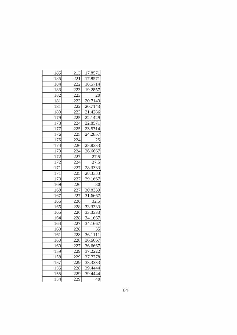
84
185 213 17.8571185 221 17.8571184 222 18.5714183 223 19.2857182 223 20181 223 20.7143181 222 20.7143180 223 21.4286179 225 22.1429178 224 22.8571177 225 23.5714176 225 24.2857175 224 25174 226 25.8333173 224 26.6667172 227 27.5172 224 27.5171 227 28.3333171 225 28.3333170 227 29.1667169 226 30168 227 30.8333167 227 31.6667166 226 32.5165 228 33.3333165 226 33.3333164 228 34.1667164 227 34.1667163 228 35161 228 36.1111160 228 36.6667160 227 36.6667159 229 37.2222158 229 37.7778157 229 38.3333155 228 39.4444155 229 39.4444154 229 40

85
154 229 40152 229 41.25151 228 41.875150 229 42.5150 228 42.5148 229 43.75147 229 44.375146 228 45145 228 45.7143145 229 45.7143144 229 46.4286143 230 47.1429142 229 47.8571142 227 47.8571141 229 48.5714140 229 49.2857139 229 50138 229 51137 228 52136 229 53135 230 54134 227 55133 229 55.7143133 229 55.7143132 229 56.4286131 229 57.1429130 229 57.8571130 229 57.8571129 227 58.5714128 227 59.2857128 227 59.2857127 227 60127 229 60126 227 60.4545125 228 60.9091

86
124 229 61.3636124 229 61.3636122 227 62.2727120 228 63.1818118 229 64.0909116 228 65116 225 65115 227 65.8333110 226 70110 226 70108 227 71.4286107 225 72.1429106 227 72.8571105 226 73.5714105 225 73.5714104 226 74.2857102 226 75.4545101 225 75.9091100 225 76.363699 224 76.818298 225 77.272797 223 77.727396 225 78.181895 223 78.636495 220 78.636494 224 79.090992 225 8091 224 80.555690 223 81.111188 224 82.222287 222 82.777886 223 83.333385 223 83.888984 221 84.4444

87
82 222 8682 222 8681 221 8780 222 8878 219 9077 220 90.416776 221 90.833375 218 91.2574 219 91.666772 218 92.572 217 92.571 219 92.916771 217 92.916770 218 93.333369 218 93.7568 217 94.166766 215 9565 215 9664 215 9740 201 9840 201 9839 200 9961 214 10060 214 10136 197 102.558 211 10336 196 103.7557 211 10456 212 10533 195 10555 212 105.62534 194 10653 210 106.87531 193 10752 208 107.5

88
31 192 10851 208 108.12549 206 109.37529 190 11028 189 110.546 207 111.11128 187 111.526 186 11244 204 112.22244 203 112.22224 184 11342 202 113.33324 183 113.523 181 114.522 178 116.66721 177 117.518 175 119.16719 174 12019 173 120.518 172 12118 169 122.516 168 12316 167 123.515 166 12414 164 12513 162 126.42914 161 127.14313 157 13014 157 13014 156 130.83313 155 131.66713 152 134.16714 149 135.71413 148 136.07113 147 136.429

89
14 145 137.14313 141 138.57114 140 138.92914 139 139.28613 138 139.64314 136 140.513 135 14114 135 14114 134 141.514 133 14214 132 142.514 131 14313 130 143.514 129 14414 128 144.514 127 14514 127 14514 126 145.514 125 14613 124 146.514 122 147.514 121 14814 119 14913 118 149.514 115 150.83314 114 151.2514 111 152.513 110 152.91714 109 153.33313 106 154.58314 105 15514 103 155.62513 99 156.87514 98 157.18813 95 158.125

90
15 93 158.7514 92 159.06315 90 159.68815 88 160.38516 87 160.76917 85 161.53818 83 162.30817 82 162.69218 82 162.69218 81 163.07716 79 163.84619 78 164.23118 76 16521 74 165.76922 72 166.53822 71 166.92320 71 166.92319 71 166.92322 70 167.30820 70 167.30820 70 167.30820 70 167.30823 69 167.69223 69 167.69220 69 167.69223 68 168.07721 68 168.07720 68 168.07720 68 168.07719 67 168.46224 66 168.84622 65 169.23122 64 169.61523 63 17023 62 170.55623 62 170.556

91
28 61 171.11124 60 171.66717 60 171.66723 59 172.22216 58 172.77820 57 173.33316 56 173.88913 54 17533 37 17519 49 177.08333 35 18042 18 18045 16 182.14346 16 182.85748 15 184.28651 14 186.11154 13 187.77855 12 188.33358 11 19061 12 192.14363 12 193.57165 11 19568 12 19870 13 20071 11 200.62576 12 203.7579 12 205.55690 12 211.66792 12 212.77894 12 213.88998 11 216.111
103 12 218.889106 12 220.357107 12 220.714108 12 221.071109 12 221.429

92
111 11 222.143112 11 222.5112 11 222.5114 12 223.214118 11 224.643122 11 226.154126 12 227.692130 12 229.231134 10 231.111136 12 232.222139 12 233.889142 14 235.385143 14 235.769145 15 236.538148 17 237.692149 18 238.077151 17 238.846155 20 240.417159 23 242.083161 26 242.917166 29 245166 30 245166 30 245167 29 245.5167 30 245.5168 29 246172 41 248175 40 249.5175 44 249.5178 53 251179 48 251.5182 49 253187 61 275186 62 275.385187 62 275.385

93
189 65 276.538190 66 276.923190 69 278.077189 70 278.462199 89 289.091200 90 289.545200 91 290202 97 292.143200 98 292.5202 100 293.214203 105 295206 118 302.727207 121 304.091207 129 308.75207 132 310.455206 133 310.909207 137 312.727208 145 316.875207 146 317.5208 148 318.75207 151 320.556205 155 322.778206 158 324.444202 174 335207 179 337.778204 181 338.889203 184 340.714203 188 343.571203 193 347.5203 194 348.333203 194 348.333218 198 351.429218 199 352.143218 200 352.857217 201 353.571216 201 353.571

94
215 202 354.286214 202 354.286212 204 356.667