development of an articulated mine-detecting … · development of an articulated mine-detecting...
TRANSCRIPT
Journal of Mechanical Science and Technology 25 (4) (2011) 1051~1060
www.springerlink.com/content/1738-494x DOI 10.1007/s12206-011-0211-8
Development of an articulated mine-detecting manipulator
system for mobile robots† Seungnam Yu1,*, Changhwan Choi1, Seungyeol Lee2, Jeongyeob Lee3 and Changsoo Han4,*
1Fuel Cycle System Eng. Tech. Development Division, Korea Atomic Energy Research Institute, 305-353, Korea 2Center for Cognitive Robotics Research, Korea Institute of Science and Technology, 136-791, Korea
3Hyundai-Rotem Co. Ltd, 437-718, Korea 4Department of Mechanical Eng., Hanyang University,426-791, Korea
(Manuscript Received August 30, 2010; Revised November 13, 2010; Accepted January 2, 2011)
----------------------------------------------------------------------------------------------------------------------------------------------------------------------------------------------------------------------------------------------------------------------------------------------
Abstract This paper presents a servo motor selection technique for a mobile mine detection system which is operated in the field condition. As a
first step, mine detection sensor should follow the earth profile while maintaining a constant distance to the earth surface. In order to acquire a reasonable manipulator trajectory and its required torque, a kind of modeling technique is devised to remove the unwanted fluctuations in the earth data. Then, Straete et al.’s normalization method is adopted and is improved to select the adequate actuator for each joint of manipulator. The improvements are as follows: First, an equivalent output power lines are plotted at the same load curve, which gives another selection criterion. Second, a temperature based criterion is proposed for the continuous limit, which estimates the steady state winding temperature of a motor, and can be used to determine a suitable motor and gear ratio. This formulation gives not only the selection of a motor and gear ratio, but also gives the estimated operating temperature. Finally, realized system is verified through the basic performance test.
Keywords: Mine detection; Wheeled manipulator; Performance analysis; Mobile robot ---------------------------------------------------------------------------------------------------------------------------------------------------------------------------------------------------------------------------------------------------------------------------------------------- 1. Introduction
In many countries, large numbers of mines are buried, espe-cially at hotspots, because of their cheap cost. Nowadays, however, the explosive mine disposal ordinance requires more skillful workers. Therefore, an automatic system is strongly required and a manned or unmanned vehicle system for mine detection is continuously being developed. This study focuses on the manipulator system for mine detection that is installed in these mobile systems, and introduces the entire process and methodology of developing a mine detection manipulator. The factors that mostly influence actuation of manipulator per-formance are its kinematic design and its control system de-sign, among others. Dynamic performance of a manipulator is especially influenced by its mechanical lightness and the im-provement of its actuator performance. Motor selection is one of the most important tasks in the design of a high-performance manipulator. Pasch and Seering suggested a re-duction ratio to minimize the moving time or to maximize the
motion acceleration when only the inertial load is considered [1]. Centinkunt proposed a method of selecting the mechani-cal parts and the control unit in the case of an inertial load [2]. Most researchers have mainly proposed a selection methodol-ogy. This approach, however, requires additional dynamic simulation for manipulator performance analysis because of its non-linearity. Chedmail and Gautier proposed an optimal method of motor selection through recursive analysis. How-ever, recursive analysis requires a heavy computational load. Therefore, Straete et al. simplified the motor selection process by separating the terms of the load torque and the load veloc-ity through normalization [3, 4]. They also proposed an im-proved motor selection method for the induction motor by expanding the condition of the switching limit of the motor brush and the rated input current [5]. The Newton-Euler method [6] and the Lagrangian method [7] are generally used for the derivation of a dynamic equation. Paul derived general dynamic equations of a rigid manipulator [8]. Leu and Hemati develop the automatic symbolic dynamic equation derivation program by using MACSYMA [9]. Cetinkunt and Book [10] derived a dynamic equation for the general flexible link ma-nipulator proposed in [7]. Cetinkunt and Ittoop [11] developed its implementation by using a symbolic mathematic package, REDUCE. These kinds of formulation and symbolic tools can
† This paper was recommended for publication in revised form by Associate Editor Yang Shi
*Corresponding author. Tel.: +82 31 400 4062, Fax.: +82 31 406 6398 E-mail address: [email protected]
© KSME & Springer 2011
1052 S. Yu et al. / Journal of Mechanical Science and Technology 25 (4) (2011) 1051-1060
be used for the dynamic analysis. In this study, Simmechan-ics® toolbox of MATLAB/ SIMULINK® is used because it is easy to realize dynamic model based on a visualized ladder logic programming tool and designed model can be integrated with motion command algorithm simultaneously. Therefore, we can focus on the motor selection criteria and its numerical analysis.
Main issues of this paper are as follows. First, the required performance is analyzed and the reference trajectory of the manipulator is generated. Second, the motor specifications are selected through dynamic simulation. Using the simulation results, the motor that would be used to actuate the real ma-nipulator system is selected and a structural analysis of the manipulator system is performed. Finally, realized system is verified through the basic performance test.
2. Kinematic modeling of manipulator
2.1 Forward kinematics of manipulator system
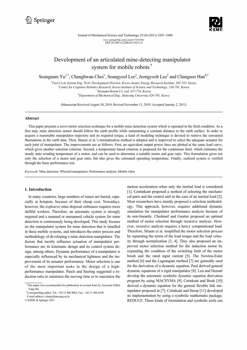
The motor selection technique was applied in the design of a manipulator to detect field mines. Fig. 1 shows the kine-matic structure and the coordinate definition of the designed system respectively. Since the manipulator is operated in a predetermined mounting position, the mounting mechanism was ignored in the model. The base position was located at the azimuth axis of the manipulator, which was denoted as the
0 0 0x y z− − coordinate system. The Denavit-Hartenberg pa-rameters are described in Table 1. The position and orientation of the mine detector sensor attached at the end of the manipu-lator should be controlled so that the sensor can follow the target earth surface that will be investigated. Since the rota-tions of the mine detector sensor in the normal direction of an earth surface are not important because of the symmetric re-sponse of the mine detector. Therefore, it is sufficient for the manipulator to control only 5-DOF, which refers to the three position components of the center of the mine detector and the two orientation components.
The sensor position and orientation with respect to the base coordinate system was represented by a 4x4 homogeneous transformation matrix, which was computed by multiplying
each joint transformation matrix, as follows:
5 1 2 3 4 5T A A A A A= (1) where iA is ith link transformation matrix. Since 5T is an orthogonal matrix, each element of the matrix is not an inde-pendent parameter. Therefore, a set of generalized coordinates had to be determined to describe the motion of the mine sen-sor. The generalized coordinate is defined as:
[ ]TX x y z φ θ ψ= (2)
[ ]1 2 3 4 5Tq q q q q q= (3)
where x, y, and z describe the position of the sensor; φ, θ, and ψ describe the orientation of the sensor in the zyz-type Euler angle; and qi, i = 1...5 describe the joint coordinates
( )X F q= . (4)
Eq. (4) is called the “forward kinematic equation of the ma-nipulator.” When a joint angle was determined, the position and orientation of the sensor were computed using the said equation. 2.2 Inverse kinematic of manipulator system
In general, the tasks of a manipulator are given with respect to a trajectory in the Cartesian coordinate system. The joint angles had to be determined from the trajectory, which is called “inverse kinematic analysis” of an ‘inverse kinematic problem.” Since Eq. (4) is highly non-linear and consists of m equations with n unknowns, there is no closed-form solution to the inverse problem, except for a simple manipulator con-figuration. Here, m is the number of the Cartesian coordinate trajectory and n is the number of joints. The values of m and n were 6 and 5, respectively, in the case of the mine detection manipulator. Therefore, a linearization method using a Jaco-bian manipulator was deemed to be the general approach to solving the inverse kinematic problem, which approximates the solution in the neighborhood of a specific joint coordinate. Considering an infinitesimal displacement in the Cartesian and joint coordinate systems, and representing the linearized equa-tion with respect to the infinitesimal joint coordinate, gives,
( )q J q Xδ δ+= (5)
Fig. 1. Design concept of the mine detection manipulator.
Table 1. Denavit-Hartenberg notation of the designed manipulator.
Link iθ id ia iα
1 1θ 135 0 / 2π−
2 2θ 0 557 0
3 3θ 0 400 0
4 4 / 2θ π− 0 0 / 2π
5 5θ 375 -135 0
S. Yu et al. / Journal of Mechanical Science and Technology 25 (4) (2011) 1051-1060 1053
where J (q) is the manipulator Jacobian matrix, 1( ) ( )T TJ q J JJ+ −= is the pseudo inverse of the Jacobian, and
[ ]TX dx dy dz x y zδ δ δ δ= (6)
[ ]1 2 3 4 5Tq dq dq dq dq dqδ = (7)
where dx, dy, and dz are the infinitesimal translations of the platform along the X, Y, and Z axes, respectively, and δx, δy, and δz are the infinitesimal angular rotations of the platform relative to the same axes. Note that δx, δy, and δz are not the infinitesimals of the Euler angles. Eq. (5) can be used not only when m = n but also when m < n or when m > n. When m ≠ n, the equation will yield an optimal solution in the least-square sense. The orientation was represented using Euler angles in Eq. (2). The infinitesimal orientations in Eq. (6), however, were denoted as infinitesimal changes in each axis of the Car-tesian coordinate system. To use Eq. (5), a coordinate trans-formation is required. The relationship between the infinitesi-mal displacement of the Euler angle e and the infinitesimal angular rotations in the Cartesian coordinates ω can be rep-resented as:
Ceω = (8) where
[ ]Tx y zω δ δ δ= , (9)
[ ]Te d d dφ θ ψ= , (10)
0 sin cos sin0 cos sin sin1 0 cos
Cφ φ θφ φ θ
θ
−⎡ ⎤⎢ ⎥= ⎢ ⎥⎢ ⎥⎣ ⎦
. (11)
A trajectory can be obtained at the joint coordinates by add-
ing the infinitesimal joint displacement computed from Eqs. (5) to (11) to the current joint coordinate. If ground informa-tion is provided, the trajectory of the proposed manipulator to follow the ground profile can be calculated in Cartesian and
joint space [6].
3. Required MDS performance analysis
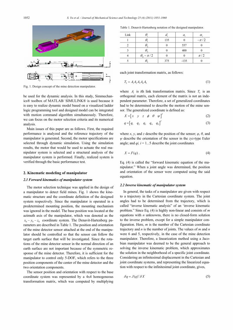
One of the main issues in MDS (mine detection system) is detecting performance to cover a wide range as fast as possi-ble. To do this, the MDS manipulator has to be operated quickly. The mine detection sensor, however, limits the mov-ing velocity of the manipulator because of its intrinsic per-formance limit. The manipulator’s moving velocity must be maximized to cover the width of the vehicle, and at the same time, the vehicle’s driving velocity must be maximized.
1. Objective: Maximize the driving velocity of manipulator integrated a vehicle system.
2. Constraints 1) The sensor attached at the end-effector of manipulator
must scan the entire ground area in front of the vehicle. 2) The range of the detection speed must be considered in
the analysis of the sensor scanning performance. Formulized as an optimization problem, Maximize 1y& ,
2 21 1
1
. .
.2
x y s
s
s t p p v
dy t
+ ≤
≤
& &
& (12)
The value of each variable is shown in Fig. 2. 1y is the di-
rection of the moving distance to the driving way; 1 1,x yp p are the absolute velocities of the mine detection sensor; sv and
sd are the maximum scanning velocity and diameter of the sensor’s detection range, respectively, and t is the time it will take for the manipulator to reciprocate once. The absolute position of the mine detection sensor can be expressed as fol-lows:
1 sinxp R θ= (13)
1 1 cosyp y R θ= + (14) where R and θ are the length and the rotation angle of the manipulator, respectively. If Eqs. (13) and (14) are substituted into Eq. (12), a relatively simple simultaneous equation will be obtained, and its calculation will lead to an inequality in the robot velocity, as follows:
2 2 2
10 sin cossy R v Rθ α θ α≤ ≤ − + −& && (15)
104
sdy θα
≤ ≤&
& (16)
where
22 .
rWacosR
t
α
αθ
=
=&
(17)
Fig. 2. Reqired performance analysis for manipulator system.
1054 S. Yu et al. / Journal of Mechanical Science and Technology 25 (4) (2011) 1051-1060
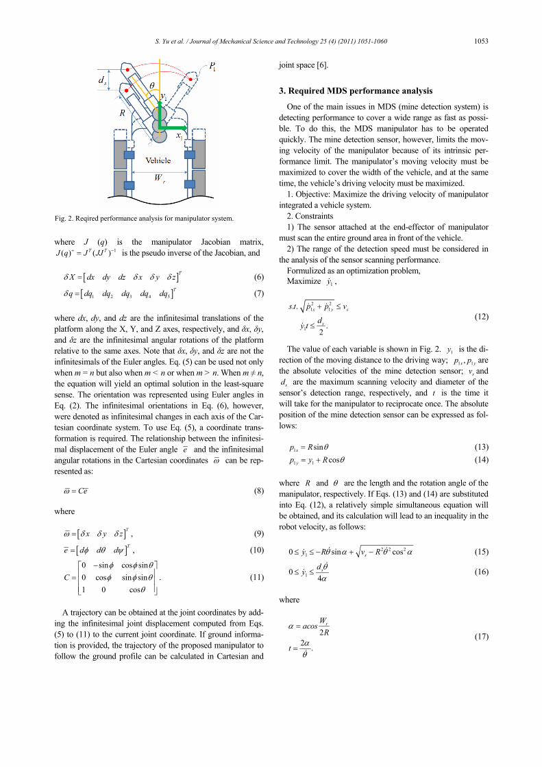
In this study, the ERA & VALLON Minehound VMR2® (metal detector + ground-penetrating radar) sensor, which has a maximum detection speed of 1.5 m/s and a detection range of 220 mm, was used. If Eqs. (15) and (16) are plotted under the assumption that the manipulator length is 0.746 m and the robot body width is 1.62 m, the results in Fig. 3 will be ob- tained. Eq. (15) was derived from the scanning velocity limit of the detection sensor, and Eq. (16) is required to scan the entire area of the ground. The rotation velocity of the manipu-lator that maximized the moving velocity of the robot within a scope that satisfied the two equations was found as shown in the figure. When the manipulator velocity was 84.4 deg/s = 90 deg/s, the moving velocity of the robot was 173 m/h.
4. Actuator selection via kinematic analysis of the manipulator while considering the terrain
4.1 Target terrain consideration
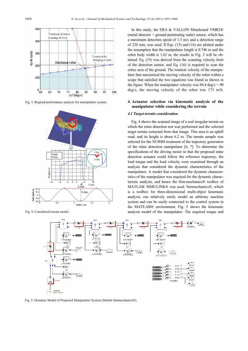
Fig. 4 shows the scanned image of a real irregular terrain on which the mine detection test was performed and the selected target terrain extracted from that image. This area is an uphill road, and its height is about 6.2 m. The terrain sample was selected for the NURBS treatment of the trajectory generation of the mine detection manipulator [6, 7]. To determine the specifications of the driving motor so that the proposed mine detection actuator could follow the reference trajectory, the load torque and the load velocity were examined through an analysis that considered the dynamic characteristics of the manipulator. A model that considered the dynamic character-istics of the manipulator was required for the dynamic charac-teristic analysis, and hence the Sim-mechanics® toolbox of MATLAB/ SIMULINK® was used. Simmechanics®, which is a toolbox for three-dimensional multi-object kinematic analysis, can relatively easily model an arbitrary machine system and can be easily connected to the control system in the MATLAB® environment. Fig. 5 shows the kinematic analysis model of the manipulator. The required torque and
Fig. 3. Reqired performance analysis for manipulator system.
Fig. 4. Considered terrain model.
Fig. 5. Dynamic Model of Proposed Manipulator System (Matlab Simmechanics®).
S. Yu et al. / Journal of Mechanical Science and Technology 25 (4) (2011) 1051-1060 1055
velocity of the driving motor so that it would follow the refer-ence trajectory of the mine detection sensor were obtained from the inverse kinematic analysis referred in section 3, with the reference trajectory as the input. In the control model of this system, the required torque and velocity were calculated by setting the inputs of the joint actuator block in motion and
substituting the reference trajectory of each joint into the equa-tion. When the torque was calculated from the inverse kine-matic analysis, however, had the reference trajectory not been accurately determined, the required motor torque might have been too high. Therefore, in this study, the joint torque, which is the control input that was obtained from the follow-up con-trol with the PID controllers at each joint, was used as the reference data for the motor selection. The PID control gain was determined when the response was best, with the other joints fixed. The DOF of the manipulator was 5, so that a vir-tual manipulator was formed using 3D graphics and it was connected to the analysis results using the VR toolbox to al-low easy comprehension of the analysis results (Fig. 1).
4.2 Results of the kinematic analysis
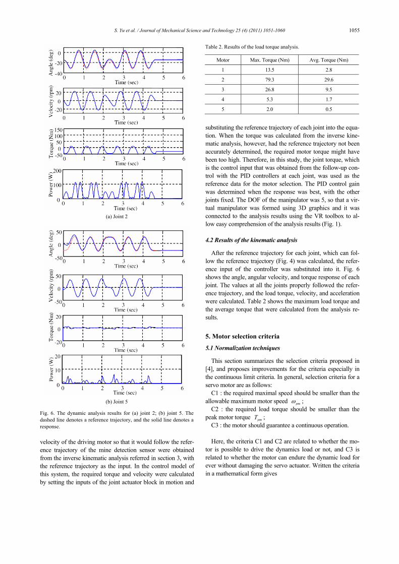
After the reference trajectory for each joint, which can fol-low the reference trajectory (Fig. 4) was calculated, the refer-ence input of the controller was substituted into it. Fig. 6 shows the angle, angular velocity, and torque response of each joint. The values at all the joints properly followed the refer-ence trajectory, and the load torque, velocity, and acceleration were calculated. Table 2 shows the maximum load torque and the average torque that were calculated from the analysis re-sults.
5. Motor selection criteria
5.1 Normalization techniques
This section summarizes the selection criteria proposed in [4], and proposes improvements for the criteria especially in the continuous limit criteria. In general, selection criteria for a servo motor are as follows:
C1 : the required maximal speed should be smaller than the allowable maximum motor speed pmω ;
C2 : the required load torque should be smaller than the peak motor torque pmT ;
C3 : the motor should guarantee a continuous operation. Here, the criteria C1 and C2 are related to whether the mo-
tor is possible to drive the dynamics load or not, and C3 is related to whether the motor can endure the dynamic load for ever without damaging the servo actuator. Written the criteria in a mathematical form gives
(a) Joint 2
(b) Joint 5
Fig. 6. The dynamic analysis results for (a) joint 2; (b) joint 5. Thedashed line denotes a reference trajectory, and the solid line denotes aresponse.
Table 2. Results of the load torque analysis.
Motor Max. Torque (Nm) Avg. Torque (Nm)
1 13.5 2.8
2 79.3 29.6
3 26.8 9.5
4 5.3 1.7
5 2.0 0.5
1056 S. Yu et al. / Journal of Mechanical Science and Technology 25 (4) (2011) 1051-1060
pl pmnω ω≤ (18)
( ) ( )lm l jm
i
T t J n t Tn
α+ ≤ (19)
where jmT means the allowable peak motor torque pmT when i indicates infinity norm, and it means the allowable average motor torque rmT when i indicates 2-norm. mJ , n , ( )lT t , ( )l tα and plω are the motor inertia, gear ratio, load torque, load acceleration, peak load velocity, respectively. Eq. (19) denotes the criteria C2 and C3 depending on the types of the norm. To determine the norm, we should compute a coupled equation which has both the load-dependent terms,
( )lT t and ( )l tα , and the motor dependent terms, mJ and n. That means we should select a candidate motor and gear ratio at first, perform the dynamic analysis, and substitute the result in the left and right side of the equation. If the inequality is not satisfied, the gear ratio needs to be adjusted. If we cannot get a suitable gear ratio, the candidate motor should be changed, and the dynamic analysis should be performed again. This kind of repeated selection procedure is required in the previ-ous techniques [2-3]. On the contrary to the previous tech-niques, we can decouple the dynamic analysis and the motor selection by a simple normalization procedure. Multiplying
mJ in both sides of Eq. (18) and dividing mJ similarly in Eq. (19) gives following equations:
* *( ) pm mn Jω ω≤ (20)
* *( ) jml
m
TT n
J≤ (21)
where
*mn J n=
* *( ) pln nω ω= (22)
* * ( )( ) ( )ll m l
i
T tT n J n tn
α= + . (23)
Although the physical meaning of n∗ includes the motor
inertia, it can be considered as a known parameter because initially we can assume that 1mJ = . Then, the left terms in Eqs. (20) and (21) have only load-dependent terms, which can be computed from simulation results. This n∗ -parameterized curve is called a ‘load curve’. After drawing a load curve, a candidate motor is substituted into the load curve by normaliz-ing the motor characteristics as given in the right terms in Eqs. (20) and (21).
Fig. 8 shows an example of a load curve. The load curve is obtained by substituting simulation results in Eqs. (22) and (23) with a parameter of n*. The upper side of the load curve satisfies Eqs. (20) and (21), and the lower side does not. To give additional criteria, constant motor power lines are drawn at the same load curve in dashed lines. Five candidate motors with different specifications are substituted into the figure and evaluation results are tabulated in the following table. The maximum allowable speed of the motor is multiplied by
mJ and the maximum allowable torque of the motor is divided by mJ . Then, a single point can be drawn for each candidate motor. The closer a candidate motor to the load curve is the more critical selection it is. In Fig. 7, the motors A, B and E are the feasible motors that can drive the dynamic load, because they are on the upper side of the load curve, whereas motors C and D are infeasible motors. Among the feasible motors, motor E is too far from the load curve, which means an overdesigned case.
Therefore, motors A and B are reasonable selections. Com-paring motors A and B, motor A has lower power than motor B, which means it can drive the dynamic load with smaller power than motor B. Once the load curve and a candidate motor are determined, the feasible gear ratio can be also com-puted from the load curve. The interaction points between the projected line in the T∗ and ω∗ axes and the load curve are the lower and upper bound of the feasible gear ratios. In the figure, n∗ values with 5 through 8 multiplied by mJ are the feasible gear ratios. This normalization technique gives a graphical representation of the feasible and infeasible motors explicitly, gives comparative information for the feasible mo-tors, and gives the feasible gear ratios. Using conditions C1 and C2, the motor for each joint was found, which drove the load shown in Fig. 6. To calculate the maximum torque condi-tion, the ∞ -norm was used in Eqs. (22) and (23). Then the following inequalities were obtained,
max | ( ) |t pmt nω ω≤ (24)
Table 3. Compatibility verification of the candidate motors.
Motor motorJ ( 2kgm ) maxT ( Nm ) peakω ( rpm ) Result
A 0.02 73.5 4389.0 O
B 0.07 357.2 974.5 O
C 0.07 198.4 137.0 X
D 0.08 56.6 2870 X
E 0.10 490.0 2717.0 O
Fig. 7. A load curve and candidate motors.
S. Yu et al. / Journal of Mechanical Science and Technology 25 (4) (2011) 1051-1060 1057
max | ( ) |mot pmtT t T≤ (25)
where pmω and pmT are the maximum velocity and the torque of the motor. The motor torque motT is the sum of the load torque and the torque from the inertia of the motor, which can be expressed as follows.
*
( )max ( )lm l pmt
T t J n t Tn
α+ ≤ . (26)
If Eqs. (24) and (26) are normalized,
*max ( ) pmtt
m
t nJ
ωω ≤ , (27)
**
( )max ( ) pmllt
m
TT t t nn J
α+ ≤
(28)
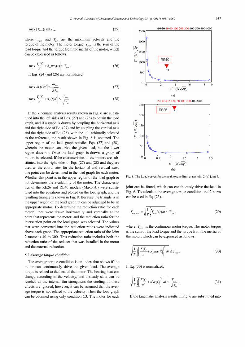
If the kinematic analysis results shown in Fig. 6 are substi-
tuted into the left sides of Eqs. (27) and (28) to obtain the load graph, and if a graph is drawn by coupling the horizontal axis and the right side of Eq. (27) and by coupling the vertical axis and the right side of Eq. (28), with the *n arbitrarily selected as the reference, the result shown in Fig. 8 is obtained. The upper region of the load graph satisfies Eqs. (27) and (28), wherein the motor can drive the given load, but the lower region does not. Once the load graph is drawn, a group of motors is selected. If the characteristics of the motors are sub-stituted into the right sides of Eqs. (27) and (28) and they are used as the coordinates for the horizontal and vertical axes, one point can be determined in the load graph for each motor. Whether this point is in the upper region of the load graph or not determines the availability of the motor. The characteris-tics of the RE26 and RE40 models (Maxon®) were substi-tuted into the equations and plotted on the load graph, and the resulting triangle is shown in Fig. 8. Because the triangle is in the upper region of the load graph, it can be adjudged to be an appropriate motor. To determine the reduction ratio for each motor, lines were drawn horizontally and vertically at the point that represents the motor, and the reduction ratio for the intersection point on the load graph was selected. The values that were converted into the reduction ratios were indicated above each graph. The appropriate reduction ratio of the Joint 2 motor is 40 to 300. This reduction ratio includes both the reduction ratio of the reducer that was installed in the motor and the external reduction. 5.2 Average torque condition
The average torque condition is an index that shows if the motor can continuously drive the given load. The average torque is related to the heat of the motor. The bearing heat can change according to the velocity, and a steady state can be reached as the internal fan strengthens the cooling. If these effects are ignored, however, it can be assumed that the aver-age torque is not related to the velocity. Then the load graph can be obtained using only condition C3. The motor for each
joint can be found, which can continuously drive the load in Fig. 6. To calculate the average torque condition, the 2-norm can be used in Eq. (23).
2,
0
1 ( )T
mot avg mot conT T t dt TT
= ≤∫ ,
(29)
where conT is the continuous motor torque. The motor torque is the sum of the load torque and the torque from the inertia of the motor, which can be expressed as follows:
2
0
1 ( ) ( )T
m conT t J n t dt T
T nα⎡ ⎤+ ≤⎢ ⎥⎣ ⎦∫ . (30)
If Eq. (30) is normalized,
2
**
0
1 ( ) ( )T
con
m
T t Tn t dtT n J
α⎡ ⎤+ ≤⎢ ⎥⎣ ⎦∫ .
(31)
If the kinematic analysis results in Fig. 6 are substituted into
(a)
(b)
Fig. 8. The Load curves for the peak torque limit at (a) joint 2 (b) joint 5.
1058 S. Yu et al. / Journal of Mechanical Science and Technology 25 (4) (2011) 1051-1060
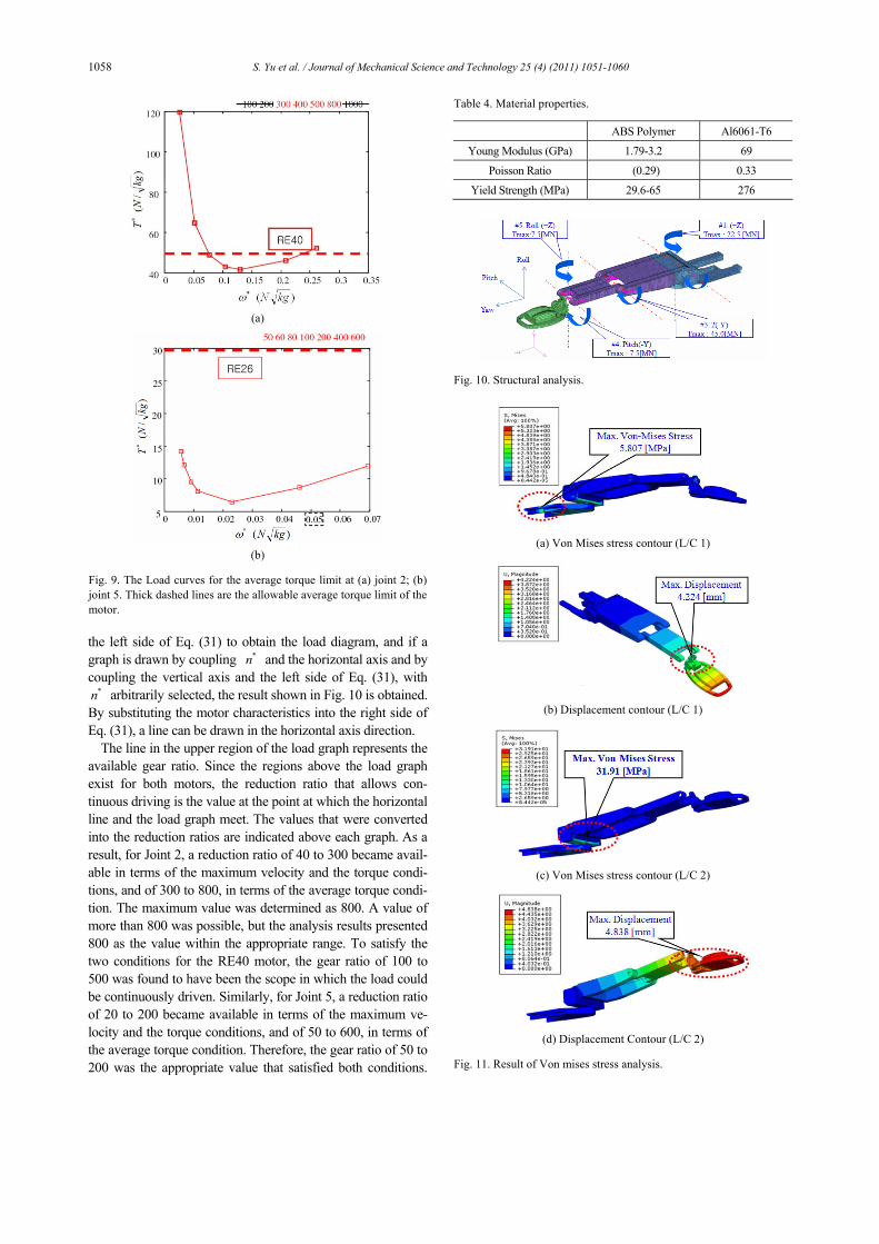
the left side of Eq. (31) to obtain the load diagram, and if a graph is drawn by coupling *n and the horizontal axis and by coupling the vertical axis and the left side of Eq. (31), with
*n arbitrarily selected, the result shown in Fig. 10 is obtained. By substituting the motor characteristics into the right side of Eq. (31), a line can be drawn in the horizontal axis direction.
The line in the upper region of the load graph represents the available gear ratio. Since the regions above the load graph exist for both motors, the reduction ratio that allows con-tinuous driving is the value at the point at which the horizontal line and the load graph meet. The values that were converted into the reduction ratios are indicated above each graph. As a result, for Joint 2, a reduction ratio of 40 to 300 became avail-able in terms of the maximum velocity and the torque condi-tions, and of 300 to 800, in terms of the average torque condi-tion. The maximum value was determined as 800. A value of more than 800 was possible, but the analysis results presented 800 as the value within the appropriate range. To satisfy the two conditions for the RE40 motor, the gear ratio of 100 to 500 was found to have been the scope in which the load could be continuously driven. Similarly, for Joint 5, a reduction ratio of 20 to 200 became available in terms of the maximum ve-locity and the torque conditions, and of 50 to 600, in terms of the average torque condition. Therefore, the gear ratio of 50 to 200 was the appropriate value that satisfied both conditions.
(a)
(b)
Fig. 9. The Load curves for the average torque limit at (a) joint 2; (b)joint 5. Thick dashed lines are the allowable average torque limit of themotor.
Table 4. Material properties.
ABS Polymer Al6061-T6
Young Modulus (GPa) 1.79-3.2 69
Poisson Ratio (0.29) 0.33
Yield Strength (MPa) 29.6-65 276
Fig. 10. Structural analysis.
(a) Von Mises stress contour (L/C 1)
(b) Displacement contour (L/C 1)
(c) Von Mises stress contour (L/C 2)
(d) Displacement Contour (L/C 2)
Fig. 11. Result of Von mises stress analysis.
S. Yu et al. / Journal of Mechanical Science and Technology 25 (4) (2011) 1051-1060 1059
The available gear ratio range was narrow in the case of Joint 2, which indicates that the motor satisfied both conditions without a significant torque or velocity margin. Joint 5 showed a wide available gear ratio scope, which indicates that the motor performed much better with the given load.
6. Manipulator design and system implementation
The Von Mises stress of the manipulator was calculated while considering the body weight and the estimated torque in the dynamic analysis to confirm the structural strength of the system, and a modal analysis was conducted to check if the natural frequency was below 10 Hz. Table 4 shows the mate-rial properties of the system, and Figs. 10 and 11 show the results of the structural analysis. In the developed system, there was one more significant torque parameter in the tension of the belt-pulley structure that constrained the joint motion but was not considered in this study. The structural analysis showed a maximum stress of 31.9 Mpa and a safety factor of 8.6 using AL6061-T6 in the first tilting joint. Moreover, the maximum displacement in the Z-direction was 4.84 mm at the end of the manipulator. The modal analysis showed that the natural frequency of the 1st mode was 10.3, which satisfied the structural requirement.
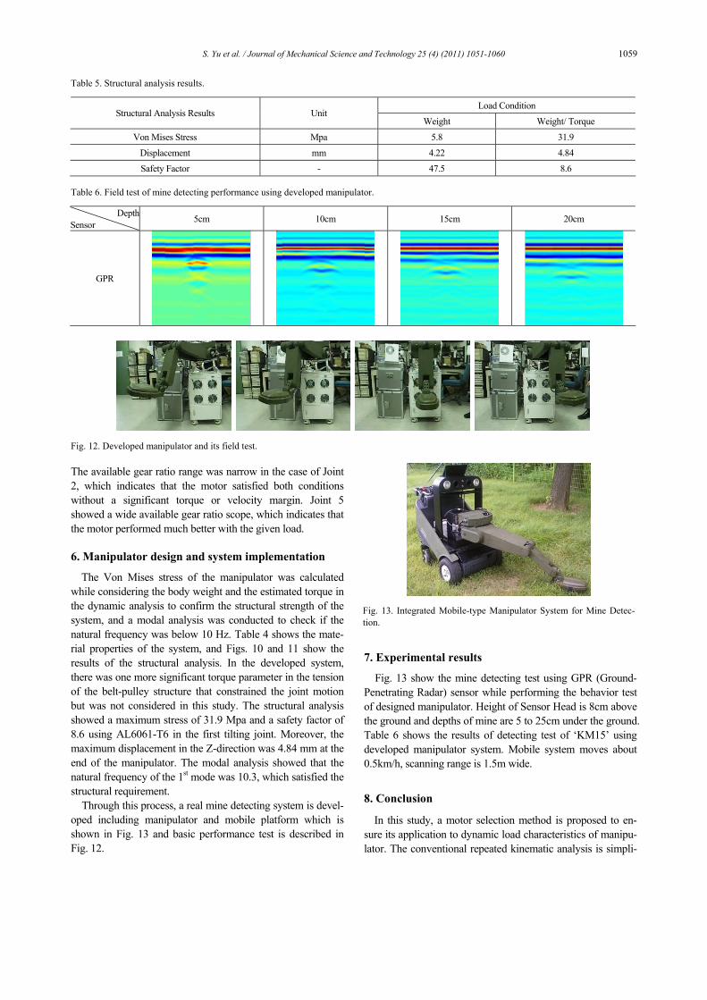
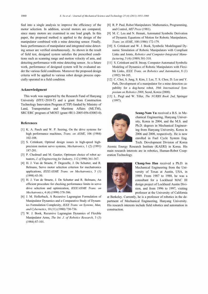
Through this process, a real mine detecting system is devel-oped including manipulator and mobile platform which is shown in Fig. 13 and basic performance test is described in Fig. 12.
7. Experimental results
Fig. 13 show the mine detecting test using GPR (Ground-Penetrating Radar) sensor while performing the behavior test of designed manipulator. Height of Sensor Head is 8cm above the ground and depths of mine are 5 to 25cm under the ground. Table 6 shows the results of detecting test of ‘KM15’ using developed manipulator system. Mobile system moves about 0.5km/h, scanning range is 1.5m wide.
8. Conclusion
In this study, a motor selection method is proposed to en-sure its application to dynamic load characteristics of manipu-lator. The conventional repeated kinematic analysis is simpli-
Table 5. Structural analysis results.
Load Condition Structural Analysis Results Unit
Weight Weight/ Torque
Von Mises Stress Mpa 5.8 31.9
Displacement mm 4.22 4.84
Safety Factor - 47.5 8.6 Table 6. Field test of mine detecting performance using developed manipulator.
DepthSensor 5cm 10cm 15cm 20cm
GPR
Fig. 12. Developed manipulator and its field test.
Fig. 13. Integrated Mobile-type Manipulator System for Mine Detec-tion.
1060 S. Yu et al. / Journal of Mechanical Science and Technology 25 (4) (2011) 1051-1060
fied into a single analysis to improve the efficiency of the motor selection. In addition, several motors are compared, since many motors are examined in one load graph. In this paper, the proposed method is applied to the design of the manipulator combined with a mine detecting sensor. Finally, basic performances of manipulator and integrated mine detect-ing sensor are verified simultaneously. As shown in the result of field test, designed system satisfies the prescribed condi-tions such as scanning range and motion velocity of arm, and detecting performance with mine detecting sensor. As a future work, performance of designed system will be evaluated un-der the various field conditions. Moreover the proposed design criteria will be applied to various robot design process espe-cially operated in a field condition.
Acknowledgment
This work was supported by the Research Fund of Hanyang University (HYU-2010-T) and a grant from Construction Technology Innovation Program (CTIP) funded by Ministry of Land, Transportation and Maritime Affairs (MLTM), SRC/ERC program of MOST (grant #R11-2005-056-03003-0).
References
[1] K. A. Pasch and W. P. Seering, On the drive systems for high performance machines, Trans. on ASME, 106 (1984) 102-108.
[2] S. Cetinkunt, Optimal design issues in high-speed high-precision motion servo systems, Mechatronics, 1 (2) (1991) 187-201.
[3] P. Chedmail and M. Gautier, Optimum choice of robot ac-tuators, J. of Engineering for Industry, 112 (1990) 361-367.
[4] H. J. Van de Straete, P. Degezelle, J. De Schutter, and R. Belmans, Servo motor selection criterion for mechatronics applications, IEEE/ASME Trans. on Mechatronics, 3 (1) (1998) 43-50.
[5] H. J. Van de Straete, J. De Schutter and R. Belmans, An efficient procedure for checking performance limits in servo drive selection and optimization, IEEE/ASME Trans. on Mechatronics, 4 (4) (1999) 378-386.
[6] J. M. Hollerbach, A Recursive Lagrangian Formulation of Manipulator Dynamics and a Comparative Study of Dynam-ics Formulation Complexity, IEEE Trans. on Systems, Man, and Cybernetics, 10 (11) (1980) 730-736.
[7] W. J. Book, Recursive Lagrangian Dynamics of Flexible Manipulator Arms, The Int. J. of Robotics Research, 3 (3) (1984) 87-101.
[8] R. P. Paul, Robot Manipulators: Mathematics, Programming, and Control, MIT Press (1981).
[9] M. C. Leu and N. Hemati, Automated Symbolic Derivation of Dynamic Equations of Motion for Robotic Manipulators, Trans. on ASME, 108 (1986) 172-179.
[10] S. Cetinkunt and W. J. Book, Symbolic Modelingand Dy-namic Simulation of Robotic Manipulators with Compliant Links and Joints, Robotics and Computer-Integrated Manu-facturing, 5 (4) (1989) 301-310.
[11] S. Cetinkunt and B. Ittoop, Computer-Automated Symbolic Modeling of Dynamics of Robotic Manipulators with Flexi-ble Links, IEEE Trans. on Robotics and Automation, 8 (1) (1992) 94-105.
[12] C. Choi, S. Jung, S. Kim, J. Lee, T. S. Choe, D. Lee and Y. Park, Development of a manipulator for a mine detection ca-pability for a dog-horse robot, 39th International Sym-posium on Robotics 2008, Seoul, Korea (2008).
[13] L. Piegl and W. Tiller, The NURBS Book 2nd, Springer (1997).
Seung-Nam Yu received a B.S. in Me-chanical Engineering, Hanyang Univer-sity, Korea in 2004, and the M.S. and Ph.D. degrees in Mechanical Engineer-ing from Hanyang University, Korea in 2006 and 2008, respectively. He is now enrolled in Fuel Cycle System Eng. Tech. Development Division of Korea
Atomic Energy Research Institute (KAERI) in Korea. His main research interests are in robotics, Human-Robot Coop-eration Technology.
Chang-Soo Han received a Ph.D. in Mechanical Engineering from the Uni-versity of Texas at Austin, USA, in 1989. From 1987 to 1988, he was a consultant for a Lockheed MAC III design project of Lockheed Austin Divi-sion, and from 1996 to 1997, visiting professor at the University of California
at Berkeley. Currently, he is a professor of robotics in the de-partment of Mechanical Engineering, Hanyang University. His research interests include field robotics and automation in construction.