development of a water cooling system for...
TRANSCRIPT
DEVELOPMENT OF A WATER COOLING SYSTEM FOR
Nd:YAG LASER CHAMBER
NOR AZIAWATI BINTI AZAHARI
A thesis submitted in fulfilment
of the requirements for the award of the degree of
Master of Science (Physics)
Faculty of Science
Universiti Teknologi Malaysia
NOVEMBER 2005

Dedication to my beloved father and mother (Azahari Yusoff and Azizah Yaman),sisters, brother and all my friends. Thanks for everything …………

ACKNOWLEDGEMENT
First and foremost I wish to give all the praise to Almighty God for giving me the
strength and time to complete this research. With His blessings may this work be
beneficial for the whole of humanity.
I’m deeply indebted to my supervisor, Associate. Professor Dr. Noriah Bidin,
for her help, guidance and encouragement throughout this work. She has thought me
her professionalism and the profound art of research which inevitably is reflected in this
thesis. For all these, and for innumerable friendly discussions we have had, I am very
grateful. Thanks also go to my co-supervisor, Dr Johari Adnan for his advice, guidance
and motivation. Without their continue support and interest, this thesis would not have
been the same as presented here.
My sincere appreciations extend to all my colleagues and friends at Laser
Technology Laboratory for their co-operation and assistance. I would also like to
acknowledge the support of my parents, sisters and brother for their kindly good
encouragement in the course of my study.
Finally, I am also indebted to Universiti Teknologi Malaysia for the financial
support in my Master study and Government of Malaysia, Ministry of Science,
Technology and Innovation for granting this project through IRPA vote, 74531.
Without this financial support, this project would not be possible.
ABSTRACT
In solid state lasers, only a small fraction of electrical input power is converted to laser radiation. The remainder of the input power is converted to heat. Therefore, solid state lasers require cooling for the pump source and active medium. In the case of flashlamp pumping usage, a cooling system in the chamber is desirable. Without adequate cooling, the laser seals, pumping cavity, lamps and the rod itself would be damaged by overheating. Thus, the aim of this project is to develop a water cooling system such that the lowest practical operating temperature is produced, and to monitor temperatures of the laser chamber during the pumping process. In order to achieve these objectives, a refrigerated water cooling system was developed which included an internal and external water cooling system. Measurements of various parameters of this water cooling system were made in order to determine its appropriateness in solid state laser chamber. A laser chamber was set-up, which comprised of a Nd:YAG laser rod, flashlamp, chamber heat sink and stainless steel blocks. An aluminium laser house was designed inclusive with electrical and water piping system. After assembling the whole system, the circulation of water in the cooling system was tested. This is to ensure no leakage occurred during the pumping process. The flow rate of water during circulation is 9.83 ± 0.01 liter / min. The minimum temperature of the cooling system that could be achieved was 18.00 ± 0.05 oC. The temperature distribution during pumping process was monitored at different points on the laser chamber. The information obtained leads to the calculation of heat dissipation from the laser chamber which operated with and without chilled distilled water. The comparison results shows that 20% improvement in heat liberated from flashlamp, whereas, 90% and 86% improvement in heat absorption in chamber heat sink and stainless steel blocks respectively. This indicated that the cooling system provided in the laser chamber was very effective in carrying out the excess heat from pumping process.

ABSTRAK
Dalam laser pepejal, hanya pecahan kecil kuasa masukan elektrik ditukarkan kepada pancaran laser. Lebihan daripada kuasa masukan ditukar kepada haba. Oleh itu, laser pepejal perlu penyejukan pada sumber pengepaman dan medium aktif. Dalam kes yang melibatkan penggunaan lampu kilat, sistem penyejukan dalam kebuk diperlukan. Tanpa penyejukan secukupnya, pelekat-pelekat dalam laser, rongga pengepaman, lampu dan rod laser sendiri akan rosak disebabkan oleh pemanasan berlebihan. Oleh itu, tujuan projek ini adalah untuk membina sistem penyejukan air supaya suhu proses terendah yang praktikal dihasilkan, dan juga untuk memantau suhu kebuk laser semasa proses pengepaman. Untuk mencapai objektif ini, sistem penyejukan air telah dibangunkan yang terdiri daripada sistem penyejukan dalaman dan luaran. Pengukuran pelbagai parameter sistem penyejukan air ini telah dilakukan dengan tujuan untuk menentukan kesesuaiannya dalam kebuk laser pepejal. Kebuk laser yang terdiri daripada rod laser Nd:YAG, lampu kilat, kebuk penebat haba dan blok keluli tahan karat telah dibina. Rumah laser aluminium juga dibangunkan yang lengkap dengan sistem saluran elektrik dan air. Selepas menggabungkan seluruh sistem, edaran air dalam sistem penyejukan diuji. Ini dilakukan untuk memastikan tiada kebocoran semasa proses pengepaman. Kadar aliran air semasa edaran diperolehi sebagai 9.83 ± 0.01 liter/ min. Suhu minimum sistem penyejukan yang dapat dicapai adalah 18.00 ± 0.05 oC. Taburan suhu semasa proses pengepaman dipantau di titik berlainan pada kebuk laser. Maklumat yang diperoleh digunakan untuk pengiraan haba dikeluarkan daripada kebuk laser dimana dikendalikan dengan dan tanpa penyejukan air suling. Keputusan yang diperolehi hasil perbandingan menunjukkan lebihan haba yang dibebaskan oleh lampu kilat dalam sistem yang disejukkan adalah 20%, sementara haba yang diserap oleh kebuk penebat haba dan keluli tahan karat masing-masing didapati bertambah sebanyak 90% dan 86% . Ini menunjukkan sistem penyejukan yang dibekalkan pada kebuk laser amat efektif untuk membawa keluar lebihan haba semasa proses pengepaman.
TABLE OF CONTENTS
CHAPTER TITLE PAGE
DECLARATION ii
ACKNOWLEDGEMENT iv
ABSTRACT v
ABSTRAK vi
CONTENT vii
LIST OF TABLES xi
LIST OF FIGURES xii
LIST OF SYMBOLS xv
1 INTRODUCTION
1.1 Overview 1
1.2 Thermal Loading of Lamp-pumped 3
Nd:YAG Lasers
1.3 Previous Research 4
1.4 Problem Statement 5
1.5 Research Objective 5
1.6 Research Scope 6
1.7 Thesis Outline 6
2 LITERATURE REVIEW
2.1 Introduction 8
2.2 Solid State Laser 8
2.3 Basic Construction of Solid State Lasers 10
2.4 The Nd:YAG Laser 12
2.4.1 Principle of Operation 13
2.5 Energy Transfer in Solid State Lasers 15
2.6 Thermo-optics Effects 16
2.7 Fundamental of Heat Transfer 17
2.8 Modes of Heat Transfer 18
2.8.1 Conduction 18
2.8.2 Convection 19
2.8.3 Radiation 19
2.9 Cooling Techniques in Solid State Lasers 20
2.9.1 Liquid Cooling 20
2.9.1.1 Water Cooler with a Liquid to Air 22
Heat Exchanger
2.9.1.2 Water Cooler with a 23
Liquid to Liquid Heat Exchanger
2.9.1.3 Water Cooler with a Refrigeration 24
Unit
2.9.2 Air or Gas Cooling 25
2.9.3 Conductive Cooling 26
2.10 Summary 27
3 DEVELOPMENT OF A WATER COOLING SYSTEM
3.1 Introduction 28
3.2 Water Cooling System 28
3.2.1 External Coolant 29
3.2.2 Internal Coolant 34
3.3 Laser Chamber 36
3.4 Lab Recorder 36
3.5 Monitoring Laser Chamber 38
4 CHARACTERIZATION OF THE WATER COOLING SYSTEM
4.1 Introduction 40
4.2 Water Temperature 40
4.2.1 Temperature of External Coolant 41
4.2.2 Temperature of Internal Coolant 43
4.3 Water Quality 46
4.3.1 The pH Level 47
4.3.2 Conductivity and Resistivity of Water 49
4.4 Summary 53
5 DEVELOPMENT OF A LASER CHAMBER
5.1 Introduction 54
5.2 Laser Chamber 55
5.2.1 Nd:YAG Laser rod 56
5.2.2 Flash lamp 56
5.2.3 Flow Tube 57
5.2.4 Stainless Steel Block 58
5.2.5 Chamber Heat Sink 60
5.2.6 Base Plate 62
5.2.7 Technical accessories 64
5.3 Assembly of the Laser Chamber 64
5.4 The Laser House 68

5.5 Piping 71
5.6 Testing the Circulation System 72
5.7 Water Flow 74
5.8 Summary 76
6 TEMPERATURE MONITORING DURING PUMPING
PROCESS
6.1 Introduction 77
6.2 Heat Loss 78
6.3 The Temperature Distribution of Laser Chamber 80
6.3.1 The Temperature Distribution of the 80
Laser Chamber with chilled water
6.3.2 The Temperature Distribution of the 84
Laser Chamber without water cooling
6.4 Heat at Different Part of the Laser Chamber 87
6.5 Summary 89
7 CONCLUSION AND SUGGESTIONS
7.1 Conclusion 91
7.2 Problems and Suggestions 93
REFERENCES 96
APPENDIX A 101
PUBLICATIONS 103
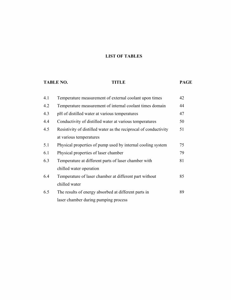
LIST OF TABLES TABLE NO. TITLE PAGE 4.1 Temperature measurement of external coolant upon times 42
4.2 Temperature measurement of internal coolant times domain 44
4.3 pH of distilled water at various temperatures 47
4.4 Conductivity of distilled water at various temperatures 50
4.5 Resistivity of distilled water as the reciprocal of conductivity 51
at various temperatures
5.1 Physical properties of pump used by internal cooling system 75
6.1 Physical properties of laser chamber 79
6.3 Temperature at different parts of laser chamber with 81
chilled water operation
6.4 Temperature of laser chamber at different part without 85
chilled water
6.5 The results of energy absorbed at different parts in 89
laser chamber during pumping process
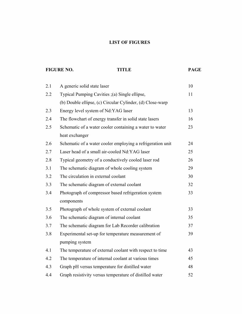
LIST OF FIGURES FIGURE NO. TITLE PAGE 2.1 A generic solid state laser 10
2.2 Typical Pumping Cavities ;(a) Single ellipse, 11
(b) Double ellipse, (c) Circular Cylinder, (d) Close-warp
2.3 Energy level system of Nd:YAG laser 13
2.4 The flowchart of energy transfer in solid state lasers 16
2.5 Schematic of a water cooler containing a water to water 23
heat exchanger
2.6 Schematic of a water cooler employing a refrigeration unit 24
2.7 Laser head of a small air-cooled Nd:YAG laser 25
2.8 Typical geometry of a conductively cooled laser rod 26
3.1 The schematic diagram of whole cooling system 29
3.2 The circulation in external coolant 30
3.3 The schematic diagram of external coolant 32
3.4 Photograph of compressor based refrigeration system 33
components
3.5 Photograph of whole system of external coolant 33
3.6 The schematic diagram of internal coolant 35
3.7 The schematic diagram for Lab Recorder calibration 37
3.8 Experimental set-up for temperature measurement of 39
pumping system
4.1 The temperature of external coolant with respect to time 43
4.2 The temperature of internal coolant at various times 45
4.3 Graph pH versus temperature for distilled water 48
4.4 Graph resistivity versus temperature of distilled water 52
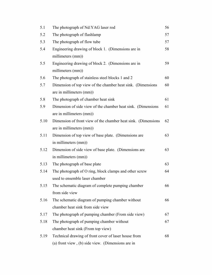
5.1 The photograph of Nd:YAG laser rod 56
5.2 The photograph of flashlamp 57
5.3 The photograph of flow tube 57
5.4 Engineering drawing of block 1. (Dimensions are in 58
millimeters (mm))
5.5 Engineering drawing of block 2. (Dimensions are in 59
millimeters (mm))
5.6 The photograph of stainless steel blocks 1 and 2 60
5.7 Dimension of top view of the chamber heat sink. (Dimensions 60
are in millimeters (mm))
5.8 The photograph of chamber heat sink 61
5.9 Dimension of side view of the chamber heat sink. (Dimensions 61
are in millimeters (mm))
5.10 Dimension of front view of the chamber heat sink. (Dimensions 62
are in millimeters (mm))
5.11 Dimension of top view of base plate. (Dimensions are 63
in millimeters (mm))
5.12 Dimension of side view of base plate. (Dimensions are 63
in millimeters (mm))
5.13 The photograph of base plate 63
5.14 The photograph of O ring, block clamps and other screw 64
used to ensemble laser chamber
5.15 The schematic diagram of complete pumping chamber 66
from side view
5.16 The schematic diagram of pumping chamber without 66
chamber heat sink from side view
5.17 The photograph of pumping chamber (From side view) 67
5.18 The photograph of pumping chamber without 67
chamber heat sink (From top view)
5.19 Technical drawing of front cover of laser house from 68
(a) front view , (b) side view. (Dimensions are in
millimeters (mm))
5.20 Technical drawing of housing from (a) front view (b) top view 69
(c) side view. (Dimensions are in millimeters (mm))
5.21 The photograph of laser (a) from top view without laser trail, 70
(b) from top view with laser trail and (c) from side view
including the laser chamber
5.22 Dimension of side view of L pipe. (Dimensions are in 71
millimeters (mm))
5.23 The photograph of L pipe 71
5.24 Schematic diagram showing circulation of cooling system 72
from coolant to the laser head
5.25 The flow path of distilled water in laser chamber 73
during circulation (top view)
5.26 The detail of circulation system in laser chamber 74
(focused in ellipsoid space)
6.1 Temperature profile at laser chamber when operated 83
with chilled water
6.2 Temperature profile without chilled water 87

LIST OF SYMBOLS Qo - Heat before
Q - Heat after
t2 - Time maximum
t1 - Time minimum
∆θ - Temperature change
cp - Specific heat
m - Mass
θ - Temperature
R - Water flow rate
v - Volume
t - Time
Pabsorbed - Power absorbed
Pi - Power input
%Pabsorbed - Percentage of power absorbed
CHAPTER 1
INTRODUCTION
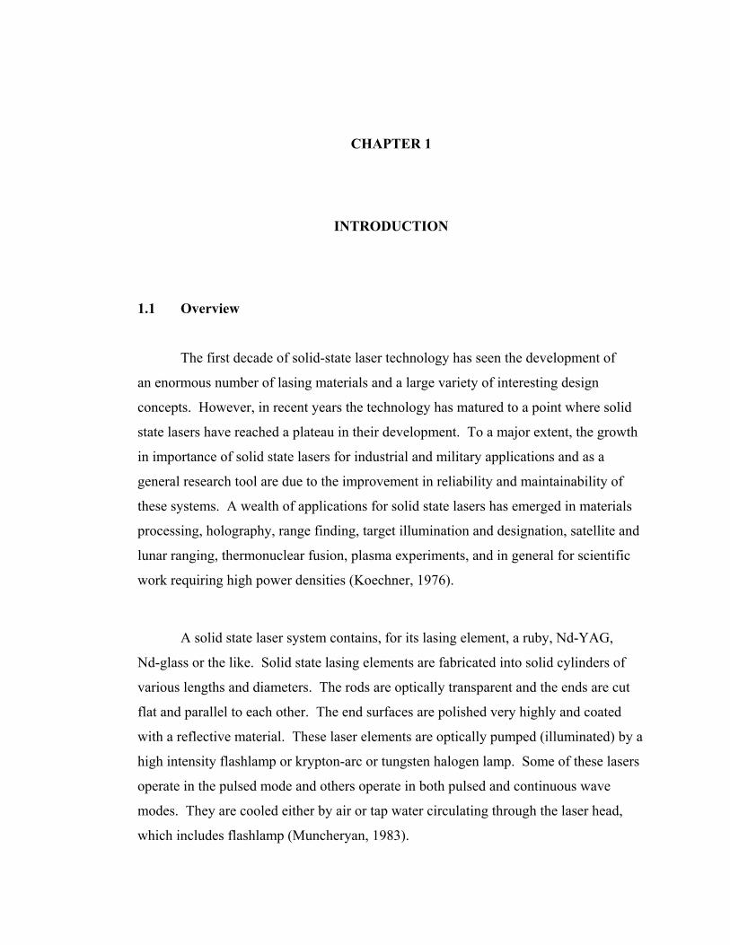
1.1 Overview
The first decade of solid-state laser technology has seen the development of
an enormous number of lasing materials and a large variety of interesting design
concepts. However, in recent years the technology has matured to a point where solid
state lasers have reached a plateau in their development. To a major extent, the growth
in importance of solid state lasers for industrial and military applications and as a
general research tool are due to the improvement in reliability and maintainability of
these systems. A wealth of applications for solid state lasers has emerged in materials
processing, holography, range finding, target illumination and designation, satellite and
lunar ranging, thermonuclear fusion, plasma experiments, and in general for scientific
work requiring high power densities (Koechner, 1976).
A solid state laser system contains, for its lasing element, a ruby, Nd-YAG,
Nd-glass or the like. Solid state lasing elements are fabricated into solid cylinders of
various lengths and diameters. The rods are optically transparent and the ends are cut
flat and parallel to each other. The end surfaces are polished very highly and coated
with a reflective material. These laser elements are optically pumped (illuminated) by a
high intensity flashlamp or krypton-arc or tungsten halogen lamp. Some of these lasers
operate in the pulsed mode and others operate in both pulsed and continuous wave
modes. They are cooled either by air or tap water circulating through the laser head,
which includes flashlamp (Muncheryan, 1983).
In all solid state laser elements, the excitation to emission occurs in the dopant,
for example the dopant is neodymium ions in the YAG lasers. The energy of radiation
from the flashlamp is at least equal or greater than the energy of the photons produced
in the respective dopant. The excited atoms are raised to a higher than normal quantum
state (energy state) from which they return to the ground state in steps, emitting photons
of wavelengths characteristics of the dopant. The greater the energy applied to the
dopant from the optical pump the greater is the intensity of the emitted radiation; this
stimulating energy does not alter the frequency of the radiation from the particular
dopant. Because the photons in the lasing cavity are produced by equal-energy photons,
any two photons in the cavity are of the same phase, frequency, amplitude and
direction. When the energy from the optical pump is not sufficient to excite the dopant
atoms to radiation, the energy in transition may dissipate in the form of heat or photons.
This condition elevates the temperature of the laser rod; the elevated temperature in the
rod tends to reduce the photon emission. So that, to prevent from overheating, the
lasing rod is cooled either by circulation of air or distilled water through the laser head
(Muncheryan, 1983).
Since Nd:YAG laser is the most powerful laser in this category, our study will
be directed to a system containing a Nd:YAG laser rod in the laser head. Thus, it is
important that during the planning stages of a laser system, careful measurement
includes water temperature, quality and flow rate must be made to provide a suitable
cooling system (Muncheryan, 1979).
1.2 Thermal Loading of lamp-pumped Nd:YAG Lasers

Consider a typical continuous wave (cw) Nd:YAG laser with an output power of
300 watts and input power of 12 kilowatts. Assuming a quantum efficiency of 50%
(low) this means that 600 watts are absorbed in the laser. Thus 11,400 watts are not
absorbed in the laser. The majority of this power is optical power from the lamps
outside the pump bands of the laser. This excess power is absorbed by the cavity and
by the lamps, thus dramatically increases the temperature of the laser. Roughly 10% to
20% of the electrical power will be dissipated as heat through the electrodes and 30% to
50% as heat through the envelope. In addition to causing mechanical overheating
problem (seals and so on), thermal gradient will cause thermal focusing in the laser rod
(Kuhn, 1998).
Typically the lamps, the cavity, and the Nd:YAG rod are cooled by water. The
usual pattern is to first take the incoming cold water and confine it to the region of the
laser rod with a flow tube. This will remove the heat deposited in the rod that is not
converted into laser light. Next, the water is allowed to flow through the major part of
the laser cavity to remove the heat deposited in the reflectors and in the cavity walls.
Finally, the water can be confined to the region around the lamps with a flow tube. This
removes the heat absorbed in the quartz envelope.
Many variations on this theme are possible depending on the total power
dissipation in the laser. For example, in extremely high average power lasers, a water
cooling loop is provided through the electrodes to avoid destroying them. In very low
power lasers, water cooling may only be provided over the lamps. In some extremely
low power lasers, it may even be possible to use air cooling (Kuhn, 1998).
1.3 Previous Research
Advanced Nd laser application which requires increasingly higher average
output power necessitate operating near the stress-fracture limit, i.e., a regime in which
output power is limited by the possibility of material fracture arising from thermally
induced stresses in the laser medium (Eggleston et al., 1984; Emmett et al., 1984).
Mangir and Rockwell (1986) have found large variations in the heat generation
accompanying flashlamp pumping of various types of Nd-doped phosphate glass and
Yittrium Aluminium Garnet (YAG). According to Chen et al., (1990) thermal effects in
flashlamp-pumped Nd:YAG lasers arise from the fact that nearly ten percent of the
flashlamp energy is converted to heat in the laser medium, while about three percent is
stored in the inversion as useful gain at the time of lasing. This heating is due to the
sizeable quantum defect between the pump spectrum and the lasing wavelength, and
quenching mechanisms.
A new mode of laser operation is proposed by Bowman (1999) which should
result in little or no heat generations within solid state laser materials. The technique
utilizes balanced spontaneous and stimulated emission within the laser medium. The
result would be a radiation balanced laser device in which no excess heat is generated
because of the average quantum defect of the radiation process is adjusted to zero. If
such a laser device can be realized, much higher average powers systems should be
possible without many of the thermal and beam quality issues that limit conventional
solid state laser.
From year 2000 onwards, the research on thermal heating in solid state laser was
more focused on diode pumped solid state laser which was found to have many
advantages over lamp-pumped solid state laser. The advantages include high system
efficiency and component lifetime and also reduction of thermal load of the solid state
laser material (Koechner, 1988). Usievich et.al, (2001) present a paper that discloses an
analytical method which delivers the exact temperature distribution in a
circularly cylindrical symmetrical, longitudinally, and transversely nonuniform heat
source distribution and circularly symmetrical cooling means. The analytical
expressions obtained for the temperature distribution open the way to a better
understanding of thermal phenomena and represent a fast tool for solid state laser
design and optimization.
1.4 Problem Statement When laser rod was pumped by flashlamp, the temperatures of the rod will
increase and the rod will expand. Such expansion will result in the change of length of
the laser cavity and may cause overheating on laser equipment. To prevent the laser rod
from experiencing drastic changes, it needs to be controlled by developing a cooling
system and monitoring the laser chamber temperatures during the pumping process.
1.5 Research Objective
The main objectives of this research are listed as follows:
1. To develop a cooling system.
2. To develop a laser chamber.
3. To measure the circulation of cooling system over the laser head.
4. To analyze dissipation of heat at different points on laser chamber during
pumping process.
1.6 Research Scope
In this study, a water cooling system and laser chamber for high power Nd:YAG
solid state laser are developed. The input power of the flashlamp used for pumping is
1.6 kW. The measured parameters of water cooling system are including water
temperature, quality and flow rate. A laser chamber is set-up which comprised of a
laser rod, flashlamp, heat sink and stainless steel blocks. A laser house is built inclusive
of electric and water piping system. The water cooling system is installed in the laser
chamber and the circulation is tested. The laser rod is pumped with flashlamp and the
temperatures at different points which include the flashlamp, stainless steel block and
chamber heat sink of the laser chamber are measured within an hour.
1.7 Thesis Outline This thesis consists of seven chapters. The first chapter reviews some of
previous research related to thermal heating in solid state laser. This chapter also
contains the objectives of the research under taken.
Chapter II covers the literature review related to the research work. This
includes the fundamental of solid state laser, thermal effect in solid state laser, the
fundamental of heat transfer and description of several types of cooling techniques used
in solid state lasers.
Chapter III describes the preparation of materials, development of water cooling
system and facilities involved in the research; and also describe the technique used to
measure temperature.
In chapter IV the measurement of various parameters of a water cooling system
is discussed. Two parameters are tested which include water temperature and water
quality in order to ensure the cooling system is appropriate for chilling of the laser rod.
The development of a laser chamber is explained in chapter V. This involves
the development of the component in the laser chamber, the design of the laser house
inclusive of an electric and water piping system and testing of the circulation of water
cooling system in the laser chamber.
Pumping of the laser rod is discussed in chapter VI. The temperature was
monitored at different part of the laser chamber. The amount of heat dissipation was
estimated based on the temperature information. The measurement was carried out with
and without chilling of the distilled water.
Finally, some conclusions of the project are drawn in chapter VII. These
include summary of the project and discussion of the problems encountered during the
work of the project; and finally last but not least, works to be carried out in the near
future are suggested.
REFERENCES
Air Conditioning and Refrigeration Institute. (1997). Refrigeration and Air
Conditioning. 3rd Edition. New Jersey: Prentice Hall.
Applied Ceramics Inc. (2003). Applied Ceramics Product Catalogue. Fremont:
Product Catalogue.
Bowman. S.R. (1999). Lasers without Internal Heating. IEEE Journal of Quantum
Electron. 35: 115-121.
Cengel, Y.A. and Boles, M.A. (1998). Thermodynamics An Engineering Approach.
Third Edition. USA: McGraw-Hill Inc.
Chen, T.S., Anderson, V.L., Kahan, O. (1990). Measurements of Heating and
Energy Storage in Diode Pumped Nd:YAG. IEEE Journal of Quantum Electron.
26: 6-8.
Coherent Laser. (2003). Laser Cooling Water Guidelines for Innova Ion Laser
Systems. Coherent Santa Clara, California: Manual Book.
Davis, C. (1996). Lasers and Electro-Optics Fundamental and Engineering.
Cambridge: Cambridge University Press.
Eggleston, J.M., Kane, T.J., Kuhn, K., Unternahrer, J., Byer, R.L. (1984). The Slab
Geometry Laser-Part I: Theory. IEEE Journal of Quantum Electron. 20: 289-
301.
Emmett, J.L, Krupke, W.F., Sooy, W.R. (1984). The Potential of High Average
Power Solid State Lasers. LLNL Livermore, CA, Rep.UCRL-53571.

Espinola, T. (1994). Introduction to Thermodynamics. United States of America:
Wm.C. Brown Inc.
Foster, J.D. Kirk, R.F. (1971). Report NASA-CR-1771, Washington D.C: NASA.
Gan, F. (1995). Laser Materials. USA: World Scientific Publishing Co. Pte Ltd.
Geankopolis, C. (1993). Transport Processes and Unit Operations. 3rd Edition.
Englewood Cliffs, New Jersey: Prentice Hall.
Hecht, J. (1992). The Laser Guidebook: Optical and Electro-optical Engineering
Series. 2nd Edition. USA: Mc-Graw Hill Inc.
Hecht, J. (1992). Understanding Lasers An Entry Level Guide. New York : IEEE
Press.
Kalisky, O. (1999). Solid state Lasers: Outlook for the Future. Connecticut USA:
Business Communications Company (BBC) Report.
Kaplan, R.A. (1964). Conductive cooling of a ruby rod, Melville New York:
Technical Note No.109.
Kelkar K.M. (2002). Design and Analysis of Liquid-Cooling Systems Using Flow
Network Modeling (FNM): Part I - Design of Cold Plate. USA: Cooling zone
Magazine.
Koechner, W. (1976). Solid State Laser Engineering. First Edition. New York:
Springer Verlag.
Koechner, W. (1988). Solid State Laser Engineering. Second Edition. New York:
Springer Verlag.
Koechner, W. and Bass, M. (2003). A Solid State Lasers A Graduate Text. New
York: Springer Verlag.
Kreith, F. (1973). Principles of Heat Transfer. 2nd Edition. Colorado: University
of Colorado, International Textbook Co.
Kren, L. and Reitz, V. (2000). Basic of Design Engineering: Fluid Power.
Cleveland, USA: Penton Media Inc.
Kuhn, K.J. (1998). Laser Engineering. Englewood Cliffs, New Jersey: Prentice-
Hall Inc.
Laser Electro optic Technology Series (LEOT) (2001). Laser Technology-Module :
CW: Nd:YAG Laser Systems. Texas: Cord Communications Inc.
Lumonics Ltd. (1991). HyperYag Laser System: Operating, Maintenance &
Servicing Manual. England: User Manual.
Lytron Ltd. (2002). Cooling System: Deionized Water. USA: Application Note.
Lytron Ltd. (2002). Cooling System: How to measure your heat load. USA:
Application Note.
Mangir, M.S., Rockwell, D.A., (1986). Measurements of Heating and Energy
Storage in Flashlamp Pumped Nd:YAG and Nd-Doped Phosphate Laser Glasses.
IEEE Journal of Quantum Electron. 22: 574-580.
Microsoft Encarta. (1999). World English Dictionary, Oxford: St. Martin's Press.
Muncheryan, H.M.(1979). Laser Technology. Indiana: Howard W.Sams & Co, Inc.
Muncheryan, H.M.(1983). Principles and Practices of Laser Technology. United
State of America: Tab Books Inc.
Nelkon, M. and Parker, P. (1980). Advanced Level Physics. London: Heinemann
Educational Books Ltd.
Paparone, F. (2004). Understanding Low-Conductivity / High Resistivity
Measurements. Oakton Instruments, Cole-Palmer Technical Library.
Rabiah, T.M. (1998) Researching Options for Process Cooling. Consulting-
Specifying Engineer. Vol. 24: 69-72
Rundle, W. (1975). Korad Division. Hadron Inc. unpublished.
Shore Laser Centre. (2000). More About Laser. New Jersey: Application Note.
Sintec Optronics Pte Ltd. (2000). Basic of Laser Technology: Nd:YAG Lasers.
Singapore: Application Notes.
Teppo, E.A. Nd:YAG Laser Technology, NWC Techn. Memo 2534 Appendix C
(1975); also Techn Note 4051-2 (1972). China Lake Calif: Naval Weapons
Centre.
Usievich, B.A., Sychugov, V.A., Pigeon, F., Tishchenko, A., (2001). Analytical
Treatment of the Thermal Problem in Axially Pumped Solid State Lasers. IEEE
Journal of Quantum Electron. 37: 1210-1214.
Wilson, J. and Hawkes, J.F.B.(1987). Lasers: Principles and Applications. United
Kingdom: Prentice Hall Inc.

Yokogawa Electric Corporation. (1997). Lab Recorder Personal Computer
Software Manual. Tokyo: User Manual.