development of a prototype telerobotic system for...
TRANSCRIPT

California AHMCT Program University of California at Davis California Department of Transportation
DEVELOPMENT OF A PROTOTYPE
TELEROBOTIC SYSTEM FOR
DEBRIS VACUUM POSITIONING
Andrew A. Porterfield Wilderich A. White Steven A. Velinsky
AHMCT Research Report UCD-ARR-00-09-14-01
Final Report of Contract 65A0039
September 14, 2000
This report has been prepared in cooperation with the State of California, Business Transportation and Housing Agency, Department of Transportation and is based on work supported by Contract Number RTA 65A0039 through the Advanced Highway Maintenance and Construction Technology Research Center at the University of California at Davis.
Copyright 2011, AHMCT Research Center, UC Davis

Development of A Prototype Telerobotic System for Debris Vacuum Positioning
ii Copyright 2011, AHMCT Research Center, UC Davis

Development of A Prototype Telerobotic System for Debris Vacuum Positioning
Technical Documentation Page 1. Report No.
FHWA/CA/NT-2001/05 2. Government Accession No.
3. Recipient’s Catalog No.
4. Title and Subtitle DEVELOPMENT OF A PROTOTYPE TELEROBOTIC
5. Report Date September 14, 2000
SYSTEM FOR DEBRIS VACUUM POSITIONING
6. Performing Organization Code
7. Author(s): Andrew A. Porterfield, Wilderich A. White, Steven A. Velinsky
8. Performing Organization Report No. UCD-ARR-00-09-14-01
9. Performing Organization Name and Address
AHMCT Center 10. Work Unit No. (TRAIS)
UCD Dept of Mechanical & Aeronautical Engineering Davis, California 95616-5294
11. Contract or Grant
RTA 65A0039
12. Sponsoring Agency Name and Address
California Department of Transportation P.O. Box 942873, MS#83
13. Type of Report and Period Covered
Final Report Jan 1999 - September 2000
Sacramento, CA 94273-0001 14. Sponsoring Agency Code
15. Supplementary Notes
16. Abstract
The Advanced Highway Maintenance and Construction Technology (AHMCT) Research Center has been developing robotic equipment and machinery for highway maintenance and construction operations. It is a cooperative venture between the University of California at Davis and the California Department of Transportation (Caltrans). The research and development projects have the goal of increasing safety and efficiency of roadwork operations through the appropriate application of automation solutions. This report describes the development of a telerobotic system for debris vacuum positioning. The center has developed a prototype of a remotely controlled articulated vacuum nozzle that is designed to permit an operator to collect litter while seated in a vehicle cab. Before and during conceptualization of this proposed solution, a thorough search of the industry was performed to find any existing machines that could be applied to the problem of collecting trash from alongside the highways. During conceptualization a variety of non-vacuum based solutions were considered. The results of the equipment search is included along with the details of the development of the final prototype. Preliminary testing was performed using a full sized truck mounted vacuum system with a fixed 12 inch diameter boom. Field testing demonstrated better than expected results and continued development of this concept is recommended.
17. Key Words
Litter, trash, telerobotic control, roadside maintenance, vacuum collection, articulated nozzle, ditch cleaner,
18. Distribution Statement
No restrictions. This document is available to the public through the National Technical Information Service, Springfield, Virginia 22161.
20. Security Classif. (of this report)
Unclassified 20. Security Classif. (of this page)
Unclassified 21. No. of Pages
102 22. Price
Form DOT F 1700.7 (8-72) Reproduction of completed page authorized (PF V2.1, 6/30/92)
iii Copyright 2011, AHMCT Research Center, UC Davis

Development of A Prototype Telerobotic System for Debris Vacuum Positioning
iv Copyright 2011, AHMCT Research Center, UC Davis

Development of A Prototype Telerobotic System for Debris Vacuum Positioning
ABSTRACT
The Advanced Highway Maintenance and Construction Technology (AHMCT) Research Center has been developing robotic equipment and machinery for highway maintenance and construction operations. It is a cooperative venture between the University of California at Davis and the California Department of Transportation (Caltrans). The research and development projects have the goal of increasing safety and efficiency of roadwork operations through the appropriate application of automation solutions. This report describes the development of a telerobotic system for debris vacuum positioning.
The center has developed a prototype of a remotely controlled articulated vacuum nozzle that is designed to permit an operator to collect litter while seated in a vehicle cab. Before and during conceptualization of this proposed solution, a thorough search of the industry was performed to find any existing machines that could be applied to the problem of collecting trash from alongside the highways. During conceptualization a variety of non-vacuum based solutions were considered. The results of the equipment search is included along with the details of the development of the final prototype. Preliminary testing was performed using a full sized truck mounted vacuum system with a fixed 12 inch diameter boom. Field testing demonstrated better than expected results and continued development of this concept is recommended.
v Copyright 2011, AHMCT Research Center, UC Davis

Development of A Prototype Telerobotic System for Debris Vacuum Positioning
vi Copyright 2011, AHMCT Research Center, UC Davis

Development of A Prototype Telerobotic System for Debris Vacuum Positioning
EXECUTIVE SUMMARY
In 1993 alone, California spent $28 million (5.6% of its annual maintenance budget) to remove 218,000 m3 (285,000 yd3) of trash from its highways and freeways (Andres, 1993). Nationally, more than one-half billion American tax dollars were spent on litter removal from roads and public areas in 1989 (Andres, 1993). The California Department of Transportation (Caltrans) is the primary organization responsible for cleaning operations on the state’s freeways. Litter clean up operations reduce the money and man-power available for other maintenance activities. In general, clean up crews must work near high-speed traffic while they manually remove small articles of trash from roadways, one item at a time into garbage bags for subsequent collection.
To improve the safety and effectiveness of this and other highway maintenance operations, the Advanced Highway Maintenance and Construction Technology (AHMCT) Research Center at the University of California at Davis (UC-Davis), ties robotics and automation technology together with current proven maintenance methods to assist crews in their work. The AHMCT Center, a partnership between Caltrans and the University, researches and develops solutions that apply automation to highway maintenance and construction tasks, especially in cases where workers are prone to injury from awkward ergonomics or are exposed to the hazards of traffic.
The AHMCT center has now developed and integrated prototype hardware with existing technology to produce a tele-robotic litter removal system. This device, known as the Automated Roadway Debris Vacuum (ARDVAC), is designed to operate in median divider areas, roadway shoulders, around guardrails, and on some embankments adjacent to roadways. The ARDVAC is capable of removing light debris such as paper, cups, aluminum cans, fast food packaging and select denser trash such as glass bottles, sections of rubber tires and surface soil or vegetation. The machine is controlled from within the safety of the vehicle’s cab, requires no on-site set-up, operates with controls of minimum complexity, and is a significant solution to the problem of roadway litter collection.
A key element to the ARDVAC’s effectiveness is its vacuum hose positioning system, whose design defines the available litter removal work area and permits automated vacuum hose motion control. This report documents the development process, from literature search to prototype testing, for all aspects of the ARDVAC’s hose positioning system.
The ARDVAC concept has performed well and, when combined with the vacuum power of a commercial vacuum truck, it is expected that this system will be an effective tool. Additional real world testing is required to optimize the design. This device could be commercialized as an add-on option for an entire array of applications not limited to roadway litter removal. It has potential uses in municipalities, state Departments of Transportation, landfill operations, and any of a variety of large-scale vacuum cleaning applications.
vii Copyright 2011, AHMCT Research Center, UC Davis

Development of A Prototype Telerobotic System for Debris Vacuum Positioning
viii Copyright 2011, AHMCT Research Center, UC Davis

Development of A Prototype Telerobotic System for Debris Vacuum Positioning
TABLE OF CONTENTS ABSTRACT................................................................................................................................... V EXECUTIVE SUMMARY......................................................................................................... VII TABLE OF CONTENTS..............................................................................................................IX LIST OF ILLUSTRATIONS ..................................................................................................... XIII LIST OF TABLES ...................................................................................................................... XV DISCLAIMER / DISCLOSURE...............................................................................................XVII CHAPTER 1 INTRODUCTION .................................................................................................... 1
1.1 Litter Problems........................................................................................................ 2 1.2 Content and Origin of Typical Roadway Litter ...................................................... 2 1.3 Locations of Typical Roadway Litter...................................................................... 3 1.4 Litter Removal Efforts ............................................................................................ 3
1.4.1 Caltrans Maintenance Crews ........................................................................... 3 1.4.2 Contract Labor ................................................................................................. 3 1.4.3 Adopt-A-Highway Volunteer Program ........................................................... 3 1.4.4 Specialty Litter Removal Equipment............................................................... 4
1.5 Literature Search ................................................................................................... 10 1.5.1 Patent Searches .............................................................................................. 10 1.5.2 Inquiries to Departments of Transportation................................................... 10 1.5.3 Web-Based Vendor Search............................................................................ 10 1.5.4 Summary of Literature Search....................................................................... 11
1.6 Summary ............................................................................................................... 11 CHAPTER 2 DEVELOPMENT OF DETAILED MACHINE SPECIFICATIONS.................... 13
2.1 Introduction ........................................................................................................... 13 2.2 Caltrans Machine Requirements ........................................................................... 13 2.3 Full-Sized Machine Specifications........................................................................ 14
2.3.1 Base Vehicle Configuration........................................................................... 14 2.3.2 Boom Assembly............................................................................................. 15 2.3.3 Computer Controls......................................................................................... 15 2.3.4 Debris Storage Bin, Particle Filtering, Dump Capacity ................................ 15 2.3.5 Electrical System ........................................................................................... 16 2.3.6 Hydraulic System........................................................................................... 16 2.3.7 Vacuum Fan Drive......................................................................................... 16 2.3.8 Vacuum Fan & Housing ................................................................................ 16 2.3.9 Vacuum Hose and Tubing ............................................................................. 17
2.4 Meeting the Specifications .................................................................................... 17 2.5 Summary ............................................................................................................... 19
CHAPTER 3 CONCEPT DESIGN OF THE HOSE POSITIONING SYSTEM ......................... 21 3.1 Introduction ........................................................................................................... 21 3.2 Design Beginnings ................................................................................................ 21
3.2.1 Nozzle Options .............................................................................................. 21 3.2.2 Boom and End-Effector Notes....................................................................... 24 3.2.3 Vehicle Interface............................................................................................ 25
3.3 Specific End-Effector Requirements..................................................................... 26 3.3.1 Sweeping Motion........................................................................................... 26
ix Copyright 2011, AHMCT Research Center, UC Davis

Development of A Prototype Telerobotic System for Debris Vacuum Positioning
3.3.2 Constant Forward Orientation ....................................................................... 27 3.3.3 Assembly Length Change.............................................................................. 27
3.4 End-Effector General Concept .............................................................................. 28 3.4.1 Additional Motion Characteristics................................................................. 29
3.5 Sweeping Arm Design .......................................................................................... 29 3.5.1 Tube Carrying End-Effector .......................................................................... 30 3.5.2 Integrated Vacuum Tube Concept ................................................................. 34 3.5.3 Sweep Arm Concept Selection ...................................................................... 36
3.6 Upper Joint and Boom Attachment....................................................................... 36 3.6.1 Specific Requirements of the Upper joint ..................................................... 36 3.6.2 Conceptualization of the Upper Joint ............................................................ 38
3.7 Summary ............................................................................................................... 41 CHAPTER 4 DETAILED DESIGN OF THE HOSE POSITIONING SYSTEM........................ 43
4.1 Introduction ........................................................................................................... 43 4.2 End-Effector Sub-Assemblies ............................................................................... 43 4.3 Upper Joint ............................................................................................................ 44
4.3.1 Upper Tray..................................................................................................... 44 4.3.2 Lower Tray .................................................................................................... 47 4.3.3 Upper Joint Compliance ................................................................................ 51
4.4 Base Design........................................................................................................... 52 4.4.1 Shaping the Base............................................................................................ 53 4.4.2 The Crown ..................................................................................................... 55 4.4.3 Short Cylinder Flange.................................................................................... 55 4.4.4 Roller Journal & Cap Seal Attachment ......................................................... 55 4.4.5 Hydraulic Manifold Placement...................................................................... 56
4.5 Fly Design ............................................................................................................. 57 4.5.1 Fly Tube......................................................................................................... 57 4.5.2 Telescopic Motion ......................................................................................... 58 4.5.3 Sealing Method.............................................................................................. 59 4.5.4 Nozzle Bracket Interface ............................................................................... 60
4.6 Nozzle Bracket ...................................................................................................... 62 4.6.1 Cylinder Flange ............................................................................................. 63 4.6.2 Dowel Pins..................................................................................................... 64
4.7 Nozzle Design ....................................................................................................... 65 4.8 Hydraulic Cylinders .............................................................................................. 66
4.8.1 Long Stroke Cylinders................................................................................... 66 4.8.2 Short Stroke Cylinder .................................................................................... 67
4.9 Controlling the End-Effector................................................................................. 68 4.10 Zinc Coating of Weldments ................................................................................ 69 4.11 Summary ............................................................................................................. 69
CHAPTER 5 ASSEMBLY NOTES AND PROTOTYPE OPERATION.................................... 71 5.1 Considerations for Device Assembly.................................................................... 71
5.1.1 The Upper Tray.............................................................................................. 71 5.1.2 The Lower Tray ............................................................................................. 71 5.1.3 The Base ........................................................................................................ 72 5.1.4 The Fly........................................................................................................... 72
x Copyright 2011, AHMCT Research Center, UC Davis

Development of A Prototype Telerobotic System for Debris Vacuum Positioning
5.1.5 The Nozzle Bracket and Nozzle .................................................................... 72 5.2 Hydraulic Power from the Auxiliary Engine ........................................................ 72 5.3 End-Effector Operation ......................................................................................... 72
5.3.1 Initial Vacuum Use ........................................................................................ 72 5.3.2 Operator Interface and Control ...................................................................... 74
5.4 Workspace and Kinematics................................................................................... 77 5.5 Upper Joint Compression Spring Array ................................................................ 79 5.6 Summary ............................................................................................................... 79
CHAPTER 6 CONCLUSIONS AND RECOMMENDATIONS ................................................. 81 6.1 Project Overview................................................................................................... 81 6.2 Suggested Modifications ....................................................................................... 81
6.2.1 The Upper Tray.............................................................................................. 81 6.2.2 The Lower Tray ............................................................................................. 81 6.2.3 The Nozzle Bracket ....................................................................................... 82
6.3 Conclusion............................................................................................................. 83
xi Copyright 2011, AHMCT Research Center, UC Davis
Development of A Prototype Telerobotic System for Debris Vacuum Positioning
xii Copyright 2011, AHMCT Research Center, UC Davis

Development of A Prototype Telerobotic System for Debris Vacuum Positioning
LIST OF ILLUSTRATIONS Figure 1.1 - The Barber Litter Picker.............................................................................................. 4 Figure 1.2 - A Vactor Sewer Cleaner.............................................................................................. 5 Figure 1.3 - The Leach Vac/All ...................................................................................................... 6 Figure 1.4 - An Elgin Street Sweeper ............................................................................................. 7 Figure 1.5 - The MadVac model 61 ................................................................................................ 8 Figure 1.6 - The MadVac model 101 ..............................................................................................8 Figure 1.7 - The MadVac model 231 ..............................................................................................9 Figure 1.8 - Pickup and trailer versions of the Giant-Vac machines .............................................. 9 Figure 2.1 – The Vac/All Engineering Design Unit...................................................................... 18 Figure 2.2 – The Centrifugal Fan Enclosure ................................................................................. 18 Figure 3.1 – Air Jet Assist Concept............................................................................................... 22 Figure 3.2 – Sweeper Brush Assist Concept ................................................................................. 22 Figure 3.3 – Moving Rake Assist Concept ................................................................................... 23 Figure 3.4 – Lawnmower Shredder Concept ................................................................................ 24 Figure 3.5 – Concrete Segment drawn into a 30.5 cm (12i n) tube .............................................. 24 Figure 3.6 – The Front End of the Fixed Overhead Boom ........................................................... 25 Figure 3.7 – The Auxiliary Engine (center of image) ................................................................... 26 Figure 3.8 – Leach Standard Control Panel .................................................................................. 26 Figure 3.9 – A Four-Bar Linkage; Top End Retains its Orientation............................................. 27 Figure 3.10 – Lift Ability of the Leach Vac/All’s Automated Boom........................................... 28 Figure 3.11 – The Initial End-Effector Concept and Axes of Motion .......................................... 28 Figure 3.12 – Nozzle Motion Controlled by a Variable Four-Bar Linkage.................................. 29 Figure 3.13 – Movement of Rotation Centerline; (a) Initial; (b) Revised..................................... 30 Figure 3.14 – Attachment of the Fly Actuator .............................................................................. 31 Figure 3.15 – Sample Track and Journal Rollers .......................................................................... 31 Figure 3.16 – The Vacuum Nozzle ............................................................................................... 32 Figure 3.17 – Hose Bending with Nozzle Rotation ...................................................................... 32 Figure 3.18 – The Nozzle Bracket Concept .................................................................................. 33 Figure 3.19 – Cylinder and Attachment to Nozzle Bracket .......................................................... 33 Figure 3.20 – Action of Parallel Cylinders Inside Sweep Arm..................................................... 34 Figure 3.21 – Sweep Arm Vacuum Seal Options ......................................................................... 35 Figure 3.22 – Nozzle Bracket for the Integrated Vacuum Tube Concept..................................... 36 Figure 3.23 – The Leach Tube Ball Joint...................................................................................... 38 Figure 3.24 – The Spring Loaded Bowl Concept.......................................................................... 39 Figure 3.25 – Bowl Insert Shifted During a Sweep Arm Collision .............................................. 39 Figure 3.26 - The Dual Tray Concept ........................................................................................... 40 Figure 3.27 – Dual Tray Assembly Shifted During a Sweep Arm Collision................................ 41 Figure 4.1 – The Fully Assembled End-Effector .......................................................................... 44 Figure 4.2 – An Upper Tray Weldment ........................................................................................ 45 Figure 4.3 – Channel of an Upper Tray Half ................................................................................ 45 Figure 4.4 – Lower Delrin Balls and Spacers in Upper Tray Channel ......................................... 46 Figure 4.5 – Upper Tray: (a) Split Halves, (b) Assembled on Boom ........................................... 46 Figure 4.6 – Upper Tray showing Gussets and Spring Bosses ..................................................... 47 Figure 4.7 – The Lower Tray Weldment....................................................................................... 48
xiii Copyright 2011, AHMCT Research Center, UC Davis

Development of A Prototype Telerobotic System for Debris Vacuum Positioning
Figure 4.8 – Top View of the Lower Tray .................................................................................... 49 Figure 4.9 – Support Flanges ........................................................................................................ 50 Figure 4.10 – Swing Pins .............................................................................................................. 50 Figure 4.11 – Short Cylinder and Mount Flange .......................................................................... 51 Figure 4.12 – The Springs of the Upper Joint ............................................................................... 52 Figure 4.13 – The Base Weldment with attached accessories ...................................................... 53 Figure 4.14 – Features of the Base Weldment .............................................................................. 54 Figure 4.15 – Base details: the crown and tube transition ............................................................ 54 Figure 4.16 – Base details; the short cylinder flange (a) before and (b) after installation of the
short cylinder......................................................................................................................... 55 Figure 4.17 – The short channel; (a) hole pattern, (b) cap seals inside the Base .......................... 56 Figure 4.18 – The Hydraulic Manifold ......................................................................................... 57 Figure 4.19 – The Fly Weldment with attached accessories......................................................... 58 Figure 4.20 – Elements of the Fly weldment ................................................................................ 59 Figure 4.21 – The vacuum seals of the Fly ................................................................................... 60 Figure 4.22 – (a) A flange bearing; (b) dowel pins....................................................................... 60 Figure 4.23 – Lift pin sleeve and gussets ...................................................................................... 61 Figure 4.24 – Lift pin .................................................................................................................... 61 Figure 4.25 – Exploded view of cylinder flange attachment and part orientations ...................... 62 Figure 4.26 – The Nozzle Bracket Weldment............................................................................... 63 Figure 4.27 – Rotation of the Nozzle Bracket............................................................................... 63 Figure 4.28 – The cylinder flange ................................................................................................. 64 Figure 4.29 – The Nozzle Bracket showing (a) the lift pin bearing and (b) a dowel bearing....... 64 Figure 4.30 – The Nozzle Weldment with attached accessories................................................... 65 Figure 4.31 – Details of the Nozzle Weldment............................................................................. 66 Figure 4.32 – Long stroke cylinder rod extensions....................................................................... 67 Figure 4.33 – The joystick controller ............................................................................................ 68 Figure 5.1 – ARDVAC and litter to be collected.......................................................................... 73 Figure 5.2 – Roadside after first pass with the ARDVAC............................................................ 74 Figure 5.3 – Seated view of the road from the driver’s seat of the Vac/All ................................. 74 Figure 5.4 – Problematic configuration......................................................................................... 75 Figure 5.5 – Ideal configuration for reaching into confined area.................................................. 76 Figure 5.6 – End-effector orientation options ............................................................................... 77 Figure 5.7 – End-Effector workspace, front view......................................................................... 78 Figure 5.8 – End-Effector workspace, top view............................................................................ 78 Figure 6.1 – Proximity of cylinder mount flanges to edge of Lower Tray ................................... 82 Figure 6.2 – Original design of cylinder pivot flange ................................................................... 82 Figure 6.3 – A potential redesign of the cylinder pivot flange ..................................................... 83
xiv Copyright 2011, AHMCT Research Center, UC Davis

Development of A Prototype Telerobotic System for Debris Vacuum Positioning
LIST OF TABLES Table 3.1 – Sweep Arm Concept Trade Table .............................................................................. 37
xv Copyright 2011, AHMCT Research Center, UC Davis

Development of A Prototype Telerobotic System for Debris Vacuum Positioning
xvi Copyright 2011, AHMCT Research Center, UC Davis

Development of A Prototype Telerobotic System for Debris Vacuum Positioning
DISCLAIMER / DISCLOSURE
The research reported herein was performed as part of the Advanced Highway Maintenance and Construction Technology (AHMCT) Program, within the Department of Mechanical and Aeronautical Engineering at the University of California, Davis and the New Technology and Research Program of the California Department of Transportation. It is evolutionary and voluntary. It is a cooperative venture of local, state and federal governments and universities.
The contents of this report reflect the view of the author(s) who is (are) responsible for the facts and accuracy of the data presented herein. The contents do not necessarily reflect the official views of the STATE OF CALIFORNIA or the FEDERAL HIGHWAY ADMINISTRATION and the UNIVERSITY OF CALIFORNIA. This report does not constitute a standard, specification, or regulation.
xvii Copyright 2011, AHMCT Research Center, UC Davis

Development of A Prototype Telerobotic System for Debris Vacuum Positioning
xviii Copyright 2011, AHMCT Research Center, UC Davis

Development of A Prototype Telerobotic System for Debris Vacuum Positioning
CHAPTER 1 INTRODUCTION
In 1993 alone, California spent $28 million (5.6% of its annual maintenance budget) to remove 218,000 m3 (285,000 yd3) of trash from its highways and freeways (Andres, 1993). Nationally, more than one-half billion American tax dollars were spent on litter removal from roads and public areas in 1989 (Andres, 1993). The California Department of Transportation (Caltrans) is the primary organization responsible for cleaning operations on the state’s freeways. Litter clean up operations generally reduce money and man-power available for other maintenance activities. Few automated clean-up options exist at this time, and obstructions to the flow of freeway traffic must be minimized. Clean up crews must work near high-speed traffic while trying to avoid injuries from the debris this traffic generates. They manually remove the pieces of trash from roadways, collecting one item at a time into garbage bags.
To improve the safety and effectiveness of these and other freeway maintenance operations, the Advanced Highway Maintenance and Construction Technology (AHMCT) Research Center at the University of California at Davis (UC-Davis), ties robotics and automation technology together with current proven maintenance methods to assist crews in their work. The AHMCT Center, a partnership between Caltrans and the University, researches and develops solutions that apply automation to highway maintenance and development tasks, especially in cases where workers are prone to injury from awkward ergonomics, or are exposed to the hazards of traffic. Previous endeavors to improve the litter removal process have been made with the AHMCT Debris Removal Vehicle (DRV). The DRV system consists of a robotic arm mounted on a truck with a compactor trash bin. This machine allows a single operator located in the cab to collect bulky items and pre-collected bagged trash from the roadside.
The AHMCT center has now developed and integrated prototype hardware with existing technology to produce a tele-robotic litter removal vacuum system. This device, known as the Automated Roadway Debris Vacuum (ARDVAC), is designed to operate in median divider areas, roadway shoulders, around guardrails, and on some embankments adjacent to roadways. The ARDVAC is capable of removing light debris such as paper, cups, aluminum cans, fast food packaging and select denser trash such as glass bottles, sections of rubber tires and surface soil or vegetation. The machine is controlled from within the safety of the vehicle’s cab. The ARDVAC will remove litter too small for the DRV to collect, but could work in conjunction with a DRV type vehicle. The ARDVAC is intended to require zero on-site set-up time, operate with controls of minimum complexity, and fill Caltrans’ need for a roadway litter and light trash removal vehicle.
A key element to the ARDVAC’s effectiveness is its vacuum hose positioning system, the design of which defines the available litter removal work area and permits automated vacuum hose motion control. This report documents the development process, from literature search to prototype testing, for all aspects of the ARDVAC’s hose positioning system.
1 Copyright 2011, AHMCT Research Center, UC Davis

Development of A Prototype Telerobotic System for Debris Vacuum Positioning
1.1 Litter Problems
The presence of litter on urban and suburban roads is much more than an eyesore to passing motorists and the maintenance crews who must clean it up. Light trash can block the flow of run-off water to storm drains developing flood conditions during rainy days. Litter can be blown into wildlife reserve areas, cluttering habitats, and items such as disposed automobile oil containers can contaminate plant and animal life. Some items may even be shredded and scattered over larger areas as seasonal mowing takes place to control plant growth and minimize fire hazards.
Large quantities of money are spent fighting the nation’s litter problems, and advertising intended to persuade the public to properly dispose of its trash has little effect. Litter items like paper and wood will decompose in time, but may be noticeable for years. Dead animals are often found on roadways, and unless they are removed, will foul the air and present unsightly views for passing motorists. Some steel items (mufflers, hub caps) may take exceptionally long to decompose, while plastics and rubber may not do so at all. All of these items should be removed from the roadway and disposed of properly.
1.2 Content and Origin of Typical Roadway Litter
The most thorough study of highway litter is attributed to Andres, who describes typical roadside litter as follows :
Roadside litter mixtures consist primarily of cardboard, rubber, plastic, glass, aluminum, steel, soil from road sweepings, lumber, dead animals, and paper in all shapes and sizes. Even household garbage and putrescibles are components of these mixtures. The materials collected are the result of machine sweeping, inlet and ditch cleaning, and roadside and rest area refuse collection. A major element of roadside litter collection is the labor intensive activity by highway maintenance workers and volunteers walking along the freeways.
Caltrans’ San Diego area reports that mattresses, paper, bottles, cans, tires, rugs, refrigerators, stoves, and ladders are commonly collected within their area of operation, with tires being the most popular litter item (Fact Sheet, District 11 Litter Program, California Department of Transportation Website). They note that maintenance crews often require “breaks” in traffic, sometimes provided by the California Highway Patrol, otherwise by lane closure crews, to remove large items from shoulders and right-of-ways.
Litter appears to come from many sources including careless drivers and poorly covered waste hauling vehicles, this despite laws in several U.S. states making it illegal to wantonly dump trash in public places. Limited federal roadway maintenance funds force departments of transportation to choose between maintaining safe, accessible roadways and fighting their litter problems.
2 Copyright 2011, AHMCT Research Center, UC Davis

Development of A Prototype Telerobotic System for Debris Vacuum Positioning
1.3 Locations of Typical Roadway Litter
Major litter accumulation areas on roadways are those nearest to on-ramps accessing fast-food establishments, along roads that lead to waste facilities, and in public rest areas. Bushes, shrubs, trees, and guardrails often catch this litter and allow it to collect in piles. Litter concentrations tend to increase in areas with higher population densities. Some expressways are less likely to collect litter if they have reduced access to communities or commercial establishments, but it should be noted that the residents and owners of these same communities and establishments often add to the litter problem themselves, unless prompted by an aware public to keep their establishments clean (Andres).
1.4 Litter Removal Efforts
1.4.1 Caltrans Maintenance Crews
Caltrans sends teams of workers to designated clean up sites with hard hats, reflective orange vests, safety glasses, long-reach tongs, and large orange garbage bags. Crews will enter median and right-of-way areas near roadways to manually remove litter and trash that has collected over time. These clean-ups are only performed a few times a year as needed in particularly filthy areas, or after several public complaints have been registered. Litter is deposited in garbage bags, one item at a time, to be collected by other members of the maintenance crew and removed to waste disposal sites. Crews assigned to all other roadway maintenance tasks will often pick up much smaller quantities of trash as they perform roadway repair duties, or flag potentially dangerous materials for pickup by a hazardous waste management team.
1.4.2 Contract Labor
Many states in the U.S. contract with prisons or detention facilities to have probationers and inmates perform litter removal tasks. According to information on the Caltrans website, “This program reduces crowding in jails and provides more than $10 million in service annually to the State of California. Probationers are non-violent offenders and are supervised at all times by Caltrans personnel…”. The procedures followed for litter clean up here are the same as in the Caltrans standard methods above.
1.4.3 Adopt-A-Highway Volunteer Program
The majority of states having submitted data to Andres’ Synthesis (38 of the 50) reported that they had Adopt-A-Highway (ADAH) programs in place. ADAH is a volunteer program organized and led by state departments of transportation that allows individuals, civic groups, communities, businesses, and charities to adopt two-mile sections of state maintained roadway. These groups organize as often as necessary during two-year periods to remove all litter and non-hazardous trash, and are recognized for their efforts with special roadway signage denoting their names and adoption status. ADAH groups are also involved in wildflower and tree planting, graffiti removal, and general roadway beautification activities. These ADAH activities allow Caltrans and other state department of transportation (DOT) maintenance crews more time to perform roadway improvements.
3 Copyright 2011, AHMCT Research Center, UC Davis

Development of A Prototype Telerobotic System for Debris Vacuum Positioning
ADAH individuals are not currently permitted to enter median roadway dividers during their clean-up activities. They are limited to working on wide shoulders and in areas where they are relatively distant from exposure to traffic. Caltrans is responsible for litter removal in medians because of the lane closures and added safety measures that must be taken for work in these areas.
1.4.4 Specialty Litter Removal Equipment
The DRV is one of several vehicles designed for or capable of roadway litter removal. The DRV is still in the testing and acceptance phases of its development, and is not applicable to removing the smaller litter items which are the focus of the ARDVAC project. The following products offer better litter and light trash removal performance, but have specific ranges of operation that may or may not be ideal for the ARDVAC project. These vehicles are typical examples of equipment currently available.
1.4.4.1 The Litter Rake Machine
Caltrans is currently testing a litter rake machine that, if proven useful, will aid in cleaning easily accessible shoulder and right-of-way areas throughout the state. The Litter Picker, built by H. Barber & Sons in Naugatuck, Connecticut, is shown in Figure 1.1. This machine is ideal for picking up most cans, bottles, hubcaps, etc., but must be pulled behind a tractor or pickup truck for use. The Barber’s operator must be conscious of litter size during operations and make height adjustments that accommodate trash of various sizes. Because of this, the Barber machine may easily miss smaller, less weighty items that can be the biggest eyesore to motorists on the freeways.
Figure 1.1 - The Barber Litter Picker
The Litter Picker requires a wide path of roadway, unencumbered by trees and bushes, to perform its cleaning operations. It is limited in that it cannot access litter underneath guardrails, and uneven terrain may cause it to miss some litter items. The metal tines used to rake litter is
4 Copyright 2011, AHMCT Research Center, UC Davis

Development of A Prototype Telerobotic System for Debris Vacuum Positioning
subject to wear and requires regular replacement. This vehicle requires some on-site set-up by maintenance crews before use.
1.4.4.2 The Sewer and Culvert Cleaners
Caltrans currently uses several large and high power suction vehicles designed for gutter, sewer, and culvert cleaning. These ditch and culvert cleaning machines generally have large waste storage bins and substantial suction power, along with a capacity to carry and pump water to break up clogs in culverts and sewers. One such vehicle built by Vactor Manufacturing in Streator, Illinois is shown in Figure 1.2. These vehicles can easily remove sludge, rocks, and sections of broken pavement from otherwise difficult to access depths. They require on-site manual set-up and use, where the operator must position the vehicle close to the intended worksite. The operator must stand outside the vehicle to manipulate the water and suction hoses for proper use, adjusting the boom angle and height hydraulically with controls on the vehicle, and then fine-tuning the placement of the nozzle head through hands-on manipulation. The vehicle cannot be moved while the suction or water-pumping operations are taking place.
Figure 1.2 - A Vactor Sewer Cleaner
These vacuum machines use an overhead rotating boom that permits placement of the vacuum nozzle head in most any position across the front of the vehicle. They are designed to carry large loads of waste and water and are usually very heavy trucks that are not ideal for use for shoulder and median operations. The water storage and pumping capacity adds mechanical complexity to vehicle maintenance and repair operations. The vacuum developed by this machine is far more than enough to pick up light trash and debris from roadways, but the typical 20.3 cm (8 in) diameter hose used to convey items to the storage bin is too small to pass many litter items.
A version of this machine with a larger hose is the Leach Company’s Vac/All, built in Oshkosh, Wisconsin. A Vac/All vehicle, as shown in Figure 1.3, has an overhead swing boom, with controls inside the cab. It allows an operator to drive the vehicle to any particular location and place the vacuum head without exiting the safety of the cab. In the typical configuration, the
5 Copyright 2011, AHMCT Research Center, UC Davis

Development of A Prototype Telerobotic System for Debris Vacuum Positioning
Vac/All machine uses a centrifugal blower to generate the high airflow through its 30.5 cm (12 in) hose.
Figure 1.3 - The Leach Vac/All
The weight of the fully equipped sewer and culvert cleaners may prove prohibitive for shoulder and median litter removal operations. These machines are not designed to rapidly move the vacuum tube nozzle and are limited to gross positioning movement. However, they have good forward visibility, good working areas for litter collection and limited on-site set-up.
1.4.4.3 Street Sweepers
Caltrans uses street sweepers to clean up roadway surface materials. Figure 1.4 shows a model produced by the Elgin Sweeper Company in Elgin, Illinois. These sweeper vehicles are designed to operate on paved surfaces and can pick up dirt, mud, leaves, paper, cans and bottles. Sweepers can operate independently of other vehicles. They can drive to a worksite at freeway speeds and begin operation without on-site manual set-up. Operators can generally choose from a left or right-hand drive depending on which side of the roadway they must clean. Many of these sweepers carry water, which is sprayed to control the dust produced by their rotating gutter and pick-up brooms.
6 Copyright 2011, AHMCT Research Center, UC Davis

Development of A Prototype Telerobotic System for Debris Vacuum Positioning
Figure 1.4 - An Elgin Street Sweeper
The water storage and pumping capacity adds mechanical complexity to vehicle maintenance and repair operations. Additionally, uneven road surfaces may permit gaps to form between either the vacuum plenum or pick-up broom and roadway, decreasing the vehicle’s cleaning effectiveness and leaving behind some litter items. Street sweepers cannot generally operate in unpaved shoulder areas without picking up significant amounts of dirt or vegetation; doing so would unnecessarily fill the vehicle’s storage bin and create undesirable dust clouds.
1.4.4.4 The Sidewalk Sweeping Machines
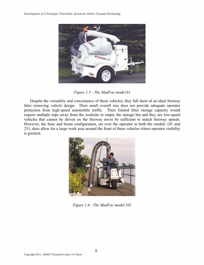
Several companies produce machines in this category. This category of machine is similar to the lawn mower in that they range in size from walk-behind equipment up to fairly large riding machines. MadVac International in Longueuil, Quebec, produces several models of the single-operator, self-contained vacuum litter removal vehicles designed for removing most small litter items. A 20.3 cm (8 in) diameter hose on all models allows operators to pick up paper, cans, bags, and bottles, with varying degrees of ease. MadVac’s model 61, shown in Figure 1.5, is a sled-mount unit that requires its operator to carry a hose to the litter for pick up. Litter storage capacity is limited to 227 L (60 gallons), though the manufacturer claims that their design causes litter to be compacted, therefore increasing its capacity. MadVac’s three-wheeled model 101, shown in Figure 1.6, allows its operator to ride along as the vehicle is driven to litter sites. Its hose is positioned through the movement of a partially automated boom, freeing the operator from carrying the hose as in the model 61. MadVac’s model 231, shown in Figure 1.7, is a four-wheeled version of the 101 with a fully automated hose boom and fully enclosed operator cab. Of the MadVac models, litter storage capacity is greatest in the model 231.
7 Copyright 2011, AHMCT Research Center, UC Davis
Development of A Prototype Telerobotic System for Debris Vacuum Positioning
Figure 1.5 - The MadVac model 61
Despite the versatility and convenience of these vehicles, they fall short of an ideal freeway litter removing vehicle design. Their small overall size does not provide adequate operator protection from high-speed automobile traffic. Their limited litter storage capacity would require multiple trips away from the worksite to empty the storage bin and they are low-speed vehicles that cannot be driven on the freeway never be sufficient to match freeway speeds. However, the hose and boom configuration, set over the operator in both the models 101 and 231, does allow for a large work area around the front of these vehicles where operator visibility is greatest.
Figure 1.6 - The MadVac model 101
8 Copyright 2011, AHMCT Research Center, UC Davis

Development of A Prototype Telerobotic System for Debris Vacuum Positioning
Figure 1.7 - The MadVac model 231
1.4.4.5 The Vacuum Loader
Vacuums in this category such as the Giant-Vac machines, built by Giant-Vac Manufacturing in South Windham, Connecticut, and shown in Figure 1.8, are primarily designed to vacuum up leaf piles. Like the MadVac model 61, the Giant-Vac’s pickup mounted and trailered machines require an operator to position the hose near the objects to be picked up, assuming the leaves have been raked into a pile for collection beforehand. Some models of the Giant-Vac have substantial leaf storage capacities, but all items collected by these machines must pass through the fan that creates the vacuum. For light, organic material such as leaves, this poses little or no problem for the heavy vacuum impeller. For litter items like cans, bottles, and rubber tire segments, damage to the impeller and drive motor due to wear, jamming and clogging becomes an immediate concern. Like the Vactor, all of Giant-Vac’s machines must be positioned near the work area and cannot be conveniently moved during operation.
Figure 1.8 - Pickup and trailer versions of the Giant-Vac machines
9 Copyright 2011, AHMCT Research Center, UC Davis

Development of A Prototype Telerobotic System for Debris Vacuum Positioning
1.5 Literature Search
Collecting a large base of information before beginning the design process is crucial to inspiring design ideas and avoiding patent infringement. Information on the vehicles and machines mentioned above, on litter removal processes, on contract litter services, and on methods currently employed by departments of transportation (DOTs) was collected from phone inquiries, library searches, and the use of search engines on the World Wide Web. Electronic searches generally made use of the keywords “debris”, “litter removal”, “trash”, “garbage”, “rubbish”, and “vacuum”, through searchable web sites such as Netscape, Infoseek, Lycos, Excite, HotBot, Google, Snap, Ask Geeves, and IBM’s Intellectual Property Network.
In all cases where vendors or DOTs appeared to have useful information, standardized electronic mail or faxes were sent to inquire for more information. The majority of web sites reviewed contained no noticeably useful information, but some did have links to pages that became invaluable. In some cases, vendor information was discovered with the on-line version of the Thomas Register of American Manufacturers or through the Public Works Journal, a directory of manufacturers and distributors of equipment used in public works design.
1.5.1 Patent Searches
Patent searches turned up no single machine directly related to removing litter from roadway surfaces. Many miscellaneous patents were discovered with regards to alternate forms of litter removal (e.g., automobile interior litter systems, chicken house litter removers, etc.), vacuum systems, boom systems, litter or contaminant removal from streams, and culvert cleaners. A vehicle or combination of equipment designed with the specific intent of the ARDVAC was not found.
1.5.2 Inquiries to Departments of Transportation
World Wide Web pages for all fifty DOTs and every link from these sites were searched for anything pertaining to litter removal or highway maintenance. All DOT sites providing search engines were queried using the keywords mentioned at the introduction of this section. No information regarding the automation of litter removal was found. All text regarding the litter removal process was in the context of state sponsored Adopt-A-Highway programs.
Page 18 of the Andres publication mentions efforts by Arizona, Minnesota, New Jersey, Ohio and Texas to either automate or contract litter removal on their roadways. These states were queried regarding their previous practices, and as with the vendor search, response was poor. Representatives from Minnesota and Texas provided the only replies, stating that previous attempts to automate litter removal produced no dependable technology (Minnesota), and that no research was currently underway (both states).
1.5.3 Web-Based Vendor Search
All web sites returned by the previously mentioned search engines and the Thomas Resister of American Manufacturers were reviewed for anything related to litter removal. Many of the
10 Copyright 2011, AHMCT Research Center, UC Davis

Development of A Prototype Telerobotic System for Debris Vacuum Positioning
listed sites had nothing to do with litter removal or vacuum applications. Those that were of interest were contacted in the hopes that information sharing or design recommendations could take place. Few companies responded to our inquiries, and most that did were only interested in selling their products to us.
1.5.4 Summary of Literature Search
The literature search provided substantial information on existing technologies and the lack of machines designed to fill the specific duties the ARDVAC seeks to perform. The search did verify that the design of a novel, useful, practical machine for litter collection on the roadways is needed.
1.6 Summary
The ARDVAC should fill a niche that is not addressed by existing equipment. The ARDVAC will pick up most lightweight and awkwardly sized trash both on and off the roadway. It will be ideal for spot clean up in locations under and behind guardrails, in amongst most highway vegetation, and on some sloping hillsides. The ARDVAC system will be integrated on an existing vacuum vehicle using proven technology. All controls for the ARDVAC will be routed into the cab of the vehicle, and there will be no on-site manual set-up required, allowing the vehicle’s operator to remain in the cab at all times. The device’s limited weight will allow maintenance crews the freedom to drive on unpaved shoulder and right-of-way sections of state freeways and highways.
The remainder of this report is organized as follows. Chapter Two details the development of machine specifications for the ARDVAC based on existing hardware and technology, the needs of Caltrans, and the perceived requirements of a flexible roadway litter removal system. Chapter Three will discuss conceptualization and selection of the hose placement system design. Chapter Four will cover the detailed design and construction of the hose placement system before Chapter Five explains the results of testing and modifications made to the placement system’s design. Chapter Six will conclude this report by summarizing the project through its current status and making recommendations on future design implementations.
11 Copyright 2011, AHMCT Research Center, UC Davis

Development of A Prototype Telerobotic System for Debris Vacuum Positioning
( This page is intentionally left blank. )
12 Copyright 2011, AHMCT Research Center, UC Davis

Development of A Prototype Telerobotic System for Debris Vacuum Positioning
CHAPTER 2 DEVELOPMENT OF DETAILED MACHINE SPECIFICATIONS
2.1 Introduction
The ARDVAC is intended to meet Caltrans’ needs for a litter removal vehicle in areas along the roadway that are not accessible by sweepers or other such machines. It will remove the majority of roadway litter in a partially automated vacuum process. It is designed to collect trash along fences, shrubbery, guardrails, medians, and some embankments by using a large vacuum nozzle that will be extended with a boom reaching forward of the vehicle’s cab and swinging to the left and right sides. The ARDVAC will be used to collect anything that can fit within the vacuum nozzle. Under normal circumstances, the operator remains within the safety of the vehicle’s cab while performing litter abatement operations. Toggle switches and a joystick controller permit vacuum hose positioning, vacuum fan operation, and all on-site set-up operations without the need to stand near hazardous high-speed traffic.
This chapter develops specifications for a prototype ARDVAC vehicle based on Caltrans’ needs and recommendations for a litter removal machine. Portions of this information will be used as the foundation for concept design of the vacuum hose positioning system in Chapter Three. The construction of a complete prototype unit will demonstrate the feasibility of critical features of this concept.
2.2 Caltrans Machine Requirements
Caltrans has specified the need to automate the process of removing litter from California’s highways. This process should be quick, efficient, and safe for the operator. The main methods for removing roadway litter considered in this project were mechanical litter picking and litter removal via suction from a vacuum. Automation of the manual litter picking process with a device such as a robotic arm and gripper is possible, but would likely add unnecessary control complexity and cost to the ARDVAC project. Attempting to grapple and transport litter with smaller, dexterous mechanical fingers or pinchers can easily complicate the kinematics of a device, and the multiple moving parts necessary for such a design to function properly are readily subject to malfunction and wear.
Use of a vacuum to remove roadway litter has advantages over other mechanical methods. Aside from the hydraulic pump or internal combustion engine that drives the vacuum fan, the fan itself is essentially the only moving part in the vacuum system. Its action can move a large volume of air so as to draw light litter items into a storage bin. A mechanical device may require stop and go vehicle motion and exact gripper placement to remove litter. By contrast, sweeping a vacuum hose back and forth with continuous vehicle motion should permit the vehicle operator to clean a large path of roadway in less time than with a mechanical litter-gripping device.
The need for an automated vacuum based litter removal machine was established by Caltrans maintenance personnel and included ideas to modify a sewer and culvert-cleaning vehicle. Caltrans has several of these culvert cleaners in its existing fleet and they are well suited to clear clogged roadway drainage systems of rocks, mud, sand, and sludge using the vehicle’s powerful
13 Copyright 2011, AHMCT Research Center, UC Davis

Development of A Prototype Telerobotic System for Debris Vacuum Positioning
high pressure blasting hose and vacuum suction system. Equipment for water storage and pumping helps break up stubborn drainage system clogs for convenient vacuum collection. An operator must park the vehicle and perform all boom and hose positioning duties while outside the vehicle’s cab. Caltrans maintenance personnel envisioned applying a similar machine to their litter removal operations to speed up the current manual process of picking up litter items individually, and to greatly augment worker safety by placing the operator inside a vehicle and away from highway traffic.
The ARDVAC concept vehicle should remove light trash from roadway surfaces. It is not intended to pick up rocks, sludge, or asphalt, nor is it required to draw water up to the vehicle. The power consuming and weighty positive displacement type compressor that creates the vacuum on most culvert-cleaning vehicles is not ideal for the trash collection application. A centrifugal type compressor is better suited to develop the high airflow for purposes of drawing light trash into a storage bin through a large diameter hose. Such a device can be lighter and require less power input than a positive displacement pump.
Litter and waste removal machines developed by various companies other than culvert-cleaning machines have individual design aspects that are appealing for the ARDVAC design, but no single vehicle encompasses every feature that would be included in the perceived ideal machine design. Taking into consideration the existing equipment and the necessary operational abilities of the ARDVAC machine, general specifications have been developed for the ideal ARDVAC.
2.3 Full-Sized Machine Specifications
The components of the ideal ARDVAC vehicle have been broken into nine main divisions. Each division stipulates an operational ability based on Caltrans’ project requirements and the AHMCT Center’s perception of a useful, flexible, user-friendly machine.
2.3.1 Base Vehicle Configuration
Addition of the hose positioning system onto existing equipment such as a sewer and culvert cleaner is preferable to the purchase of a new vehicle or a ground-up assembly in order to minimize equipment costs. The apparatus developed in this project should be mounted on a standard cab and chassis vehicle. A gross vehicle weight rating of 11,800 kg (26,000 lbs) or less, capable of carrying an additional 907 kg (2,000 lbs) of litter weight, in addition to all added equipment and an operator, is assumed to be sufficient. Minimizing net vehicle weight may permit operation on unpaved shoulders and some median roadway dividers.
If a cab-over vehicle is available, where the cab lies atop the front axle of the vehicle, the operator will have greater visibility of the workspace ahead of the vehicle. This allows boom positioning without requiring the operator to lean out of his or her seat in order to visualize placement of the vacuum nozzle. Dual steering, throttle, and brake controls permits simplified left and right side operations and increases the visible workspace but may not justify the added expense.
14 Copyright 2011, AHMCT Research Center, UC Davis

Development of A Prototype Telerobotic System for Debris Vacuum Positioning
2.3.2 Boom Assembly
The ARDVAC’s available workspace is partially defined by the motion capabilities of the boom and end-effector. The boom shall be located over the cab and should be free to rotate +/- 45o about a vertical axis from the forward orientation. The boom should conveniently carry large diameter tubing or flexible hose and an end-effector assembly weighing up to 68 kg (150 lbs). Points of rotation and all geometries of the boom must not permit kinking or binding of the hose that might distort its internal airflow. Without aid of the end-effector, the boom should reach a maximum of 3.1 m (10 ft) to either side of the vehicle.
The end-effector shall permit a lateral sweeping motion independent of the overhead boom. In other words, all sweeping motion of the end-effector shall be perpendicular to the sides of the vehicle. The boom and end-effector combined should be capable of raising and lowering the vacuum nozzle a total of 122 cm (48 in) to account for changes in roadway height and embankment slopes. This assembly shall permit placement of the vacuum nozzle partially underneath or behind guardrails. The combined hose positioning system should have a minimum number of actuators and links, and have a low design weight.
The positioning system will need to be sufficiently robust to handle dragging the vacuum nozzle alongside the vehicle in cases where action of the vacuum draws the nozzle towards a fixed object or the ground. Built-in compliance should allow minor collisions between the end-effector and fixed objects without permitting device breakage. While stowed for roadway travel, the positioning system shall not protrude beyond the width of the vehicle. There should be no need for on-site set-up that requires an operator to leave the safety of the cab. Finally, all positioning system controls should be located inside the cab, be simple to operate, and be directly related to the motion capabilities of the boom and end-effector.
2.3.3 Computer Controls
Limited computer control is required in the development of this project. A multiple function joystick is ideal for controlling boom and end-effector motion due to its user friendliness. Open loop control is expected to be sufficient. Various circuits will be required to allow electronic control of the actuators. No other computer processing power should be needed to operate the ARDVAC.
2.3.4 Debris Storage Bin, Particle Filtering, Dump Capacity
A debris storage bin with a minimum of 3.8 m3 (5 yd3) storage capacity and the ability to tilt and unload its contents is required. A lockable flap or full-sized door will permit this unloading, where all bin tilt and door operations are hydraulically actuated via controls in the cab or on the vehicle body. Some method to compact the trash is highly desirable in order to increase the collectable volume of trash. This may be accomplished in any number of ways including physically pressing the litter into a smaller volume or using the motion of the vacuum air to draw all trash items towards the base of the bin.
No litter shall pass through the fan system after being drawn into the litter storage bin. A filtering mechanism will prevent all litter and the majority of dust and small particles from
15 Copyright 2011, AHMCT Research Center, UC Davis

Development of A Prototype Telerobotic System for Debris Vacuum Positioning
entering the fan system and passing on to the environment. This will prolong the life of the components of the fan system and avoid returning any items removed from the roadway to the surroundings.
2.3.5 Electrical System
It is assumed that the vehicle used to support all ARDVAC implementations will operate on a standard 12-volt direct current electrical system. All added electrical components such as hydraulic valves, joystick controller, and indicator lights shall be appropriate for operation in a similar 12-volt system. The ARDVAC’s electrical system, though tied to the vehicle’s electrical system, should not be capable of damaging the vehicle’s electronics or hindering the vehicle’s roadworthiness. Adequate fuse protection and safety shutdown components must be installed, and all wires and major termination panels should be clearly labeled to aid in equipment maintenance. Finally, all electrical system connections shall be clearly documented for troubleshooting and failure diagnosis.
2.3.6 Hydraulic System
The ARDVAC’s hydraulic system shall be powered by the vehicle’s engine or an auxiliary engine mounted to the chassis. In either case, the vehicle must be drivable while this pump develops adequate power for all hydraulic components. The hydraulic manifold or valve body should be easily accessible for all adjustments and any maintenance that may be necessary. Proportional valves will be required to permit fine placement control of all hose positioning system components.
2.3.7 Vacuum Fan Drive
The ADRVAC machine is expected to be a dedicated trash collector and not a culvert or sewer cleaner, therefore airflow and vacuum ratings will be down rated from that of a typical culvert cleaning vacuum truck. The vacuum fan, which draws air into the storage bin at high speeds, may be driven in one of several ways depending on the fan horsepower requirements and vehicle space limitations. A belt and pulley or gear transmission may be necessary to transmit power to the vacuum fan, or it may be directly attached to a chassis mounted, auxiliary internal combustion engine. Hydraulic power may be used to drive a gear motor attached to the fan, but only where sufficient hydraulic system power exists for operation of the fan and the hose positioning system (Section 2.3.6). It may be necessary to control the speed of the vacuum fan to adjust the airflow rate, or to even have means to slow the rotational speed of the fan during system shut down. As with the rest of the hose positioning system, the vacuum fan controls and any auxiliary engine controls shall be routed to the cab of the vehicle.
2.3.8 Vacuum Fan & Housing
A centrifugal fan type vacuum pump or compressor that develops a high airflow and low vacuum must be capable of drawing air through a 30 cm (12 in) diameter hose at 320 kph (200 mph) and 6.8 kPa (2 in Hg) in order to draw in typical roadway litter but not necessarily rocks or large pieces of metal or tire. These conditions should be maintained independent of the volume
16 Copyright 2011, AHMCT Research Center, UC Davis

Development of A Prototype Telerobotic System for Debris Vacuum Positioning
of litter in the debris storage bin. The fan speed shall be determined from the above airflow and pressure constraints, and should be adjustable from the cab of the vehicle.
An exhaust muffler, set to vent discharge air vertically to the atmosphere, is highly desirable to control noise generated by the exhaust airflow. An enclosure for the fan power source may be necessary to attenuate noise generated by an auxiliary engine. Dust and particulate emissions from the vacuum system’s exhaust should be kept to a minimum. The vacuum fan should be fully enclosed with inlet and outlet ducting spaced to permit connections to the storage bin, filtering, and muffler systems.
2.3.9 Vacuum Hose and Tubing
Sections of flexible hose and rigid tubing will be necessary to route the airflow and all captured trash into the debris storage bin. The vacuum hose shall be 30 cm (12 in) in diameter in order to pass the majority of roadway litter to the storage bin, understanding that items such as re-cap tire segments, dead animals, buckets, and pallets will not be passing through this hose. The hose design should be sufficient to resist internal abrasion from glass, wood, small metal objects, and sand, but be smooth enough to not restrict the maximum operational airflow or promote clogging. The weight and bend radius of this hose must be minimized to permit convenient manipulation by the hose placement system.
Both the flexible hose and rigid tubing shall be compatible with roadside operations. They must withstand temperatures from 10 to 49 °C (50 to 120 °F), and should be resistant to ultraviolet light damage. Neither the hose nor the tubing should be susceptible to water damage, although the ARDVAC is not likely to be used in rain or snow conditions.
Rigid, smooth, lightweight tubing shall be used in all locations where bending is not expected. Use of tubing with a smooth interior will minimize litter clogging and maximize airflow. Low weight material will allow for a streamlined boom design, but weight minimization at the cost of excessively thin walls is not acceptable, as this may permit cracking and failure at impact or stress points within the rigid tube.
2.4 Meeting the Specifications
Use of a Vac/All vehicle from the Leach Company with the added hose positioning system has allowed the prototype ADRVAC to meet a majority of the specifications outlined above. Weighing in at 15,000 kg (33,000 lbs) and shown in Figure 2.1, this single rear axle cab-over engineering design unit is equipped with a 7.6 m3 (10 yd3) storage bin and a fixed overhead vacuum tube. A large windshield and side windows permit good operator visibility from the cab, and all controls for the hose positioning system, auxiliary engine, and storage bin dump exist in the cab near the driver’s seat.
17 Copyright 2011, AHMCT Research Center, UC Davis

Development of A Prototype Telerobotic System for Debris Vacuum Positioning
Figure 2.1 – The Vac/All Engineering Design Unit
The 12-volt electrical system and hydraulic circuit powered by the auxiliary engine have been accessed to provide power to all hose positioning system controls. All airflow speed and vacuum requirements are met by the Vac/All’s centrifugal fan. This fan is designed to move substantial quantities of air at relatively low vacuum levels; this is more than adequate to pick up all litter items specified by the ARDVAC project outline.
Figure 2.2 – The Centrifugal Fan Enclosure
Air exiting the centrifugal fan passes through a baffle box to aide in reducing noise generation before being exhausted upwards to the atmosphere. The majority of vacuum tubing is smooth and should not abnormally impede airflow characteristics. Use of flexible hose is limited to tube joints for rotation and compliance.
The end-effector, though designed to work with a fully movable overhead boom, will be used in proof-of-concept testing with the existing engineering unit’s fixed overhead vacuum tube. The full usefulness of the ARDVAC would be realized with a fully functional boom that will have full range of motion throughout the originally desired litter removal workspace, and will satisfy the original ARDVAC project requirements.
18 Copyright 2011, AHMCT Research Center, UC Davis

Development of A Prototype Telerobotic System for Debris Vacuum Positioning
2.5 Summary
These specifications have been developed to meet or exceed Caltrans’ expectations for an automated roadway litter removal system. The ARDVAC machine will be capable of conveniently vacuuming roadway trash to a storage and transportation bin without requiring its operator to exit the cab or handle any of the litter. Design, construction, and testing of a prototype ARDVAC machine will prove concept feasibility and provide the proper foundation for the development of a commercially viable ARDVAC machine.
19 Copyright 2011, AHMCT Research Center, UC Davis

Development of A Prototype Telerobotic System for Debris Vacuum Positioning
( This page is intentionally left blank. )
20 Copyright 2011, AHMCT Research Center, UC Davis

Development of A Prototype Telerobotic System for Debris Vacuum Positioning
CHAPTER 3 CONCEPT DESIGN OF THE HOSE POSITIONING SYSTEM
3.1 Introduction
This chapter charts the development of the hose positioning system based on design requirements laid out in Chapter Two. As previously specified, the hose positioning system should have a minimum number of parts, low total weight for the assembly of parts, and access a maximum available workspace without moving the overhead boom. Additionally, it must conveniently access the space around roadway guardrails, be relatively easy to operate, and not require any manual set-up at the worksite.
Litter will be conveyed to a storage bin via vacuum driven airflow. Air containing litter will move through thin wall tubing or flexible hose that is mounted to or incorporated within structural components of the positioning system. The function of the hose positioning system is the manipulation, by mechanical actuators, of these structural components to position a vacuum nozzle nearest to litter for collection.
3.2 Design Beginnings
Two major issues presented themselves early on in the design process. First, litter items would need to be conveyed from the ground up into the nozzle or opening of the vacuum system. Second, this nozzle at the end of a hose or tube must be physically placed near the litter by the end-effector and boom combination. Both the boom and end-effector require the freedom to manipulate around the front end of the base vehicle. The boom should be responsible for general placement of the end-effector. The end-effector will then accurately position the nozzle nearest to the litter being removed.
3.2.1 Nozzle Options
Before vacuum nozzle performance could be evaluated, assumptions were made that the air around the exterior of the nozzle being drawn into the vacuum hose may not move fast enough to lift litter from the ground. Initial design work on the ARDVAC focused on nozzle options to aid in this process. Potential configurations included directed air jets, sweeper brushes, moving rakes, and a lawnmower-type shredder.
3.2.1.1 Air Jet Assist Concept
Figure 3.1 depicts the air jet concept, where a small air nozzle mounted to a circular track may be manipulated about the end of the hose section by a rotary actuator. The intent is to help blow or push litter items closer to the vacuum hose opening. A concern with this design was whether a small air tube could withstand a collision with a stationary object such as a guardrail or large rock. In addition, observations from use of a common shop air nozzle showed that objects scatter rapidly when moved by pressurized air, and could therefore be pushed further away from the vacuum opening.
21 Copyright 2011, AHMCT Research Center, UC Davis

Development of A Prototype Telerobotic System for Debris Vacuum Positioning
Figure 3.1 – Air Jet Assist Concept
3.2.1.2 Sweeper Brush Assist Concept
Figure 3.2 shows the sweeper brush concept. With the brush set in motion, this feature is meant to sweep litter items underneath the vacuum nozzle. Like the air jet assist concept, this sweeper brush would need to be free to rotate about the end of the hose in order to move all surrounding litter close to the nozzle. However, placement of a hydraulic actuator to rotate this brush and the routing of hydraulic tubing adds weight and packaging complexity to this option. Moreover, the height of the sweeper above the ground would require constant adjustment by the vehicle operator to accommodate litter of varying sizes.
Figure 3.2 – Sweeper Brush Assist Concept
3.2.1.3 Moving Rake Assist Concept
The concept in Figure 3.3 drags litter towards the vacuum nozzle and is less likely to miss or lose the litter than the two previous concepts. Unfortunately, increasing the likeliness of seizing litter requires additional parts and control complexity. This rake arm adds joints and requires several more actuators (or a complex linkage assembly) than both of the previously discussed
22 Copyright 2011, AHMCT Research Center, UC Davis

Development of A Prototype Telerobotic System for Debris Vacuum Positioning
concepts. In addition, the protruding rake arm assembly may prohibit placement of the hose end behind guardrails and in between median shrubbery.
Figure 3.3 – Moving Rake Assist Concept
3.2.1.4 Lawnmower Shredder Concept
As a possible substitution to the large diameter hose specification, this litter lawnmower option could conceivably shred trash into smaller pieces for subsequent vacuum removal to a storage bin. As in the case of the moving rake, Figure 3.4 shows the shredder with some of the multiple arms that would be necessary to position the lawn mowing head. While it may be easier to vacuum up smaller pieces of litter, the problem of breaking up aluminum cans, glass bottles, rubber tire segments, and any rocks or wood drawn into the mower head generates lifetime, jamming, and failure issues in the design or selection of a cutting blade. Depending on the size of the lawnmower head, there may also be problems associated with reaching through median shrubs and behind guardrails.
In terms of safety, adequate protection from the rotating cutting blade would need to be designed into the mower head to prevent personal injury yet permit the blade to do its job. As with the sweeper brush, lifting of the head would be necessary to accommodate larger litter items. Finally, inadvertent collection of excessive vegetation and plant trimmings may become a problematic issue.
23 Copyright 2011, AHMCT Research Center, UC Davis

Development of A Prototype Telerobotic System for Debris Vacuum Positioning
Figure 3.4 – Lawnmower Shredder Concept
3.2.1.5 Nozzle Option Conclusions
The culvert cleaners and vacuum trucks are capable of moving large quantities of air sufficient to lift dense objects such as the irregularly shaped 2.5 kg (5.5 lb) concrete segment seen in Figure 3.5. Since the various nozzle options add mechanical complexity and control issues to the hose positioning system, these concepts were not integrated into the design. Later testing and development will further substantiate the usefulness of specialized nozzles to aid in collecting litter items or preventing non-litter items from being picked up. Chapter Five discusses the results of testing done on the non-assisted nozzle.
Figure 3.5 – Concrete Segment drawn into a 30.5 cm (12i n) tube
3.2.2 Boom and End-Effector Notes
The Leach Company’s Vac/All is generally available with an automated overhead boom. This boom’s mobility permits three degrees of freedom, including the capability to rotate about a vertical axis over the cab, the ability to telescope along the length of the boom, and the capacity
24 Copyright 2011, AHMCT Research Center, UC Davis

Development of A Prototype Telerobotic System for Debris Vacuum Positioning
to raise or lower the boom’s end. However, the Vac/All vehicle loan from the Leach Company is an engineering development unit, and is equipped with a temporary, fixed overhead boom. The end-effector conceptualized here is done so under the assumption that it will be used on a fully mobile boom, retaining its ability to accurately place the vacuum nozzle near litter collections. For these reasons, the remainder of this chapter will focus on the design of the end-effector portion of the hose positioning system.
3.2.3 Vehicle Interface
The overhead boom on the Leach Company’s Vac/All machine will support the weight of the end effector as it is positioned to collect litter. The forward portion of the boom, seen in Figure 3.6, is fixed to the front of the vehicle and ends in a rounded elbow shape with a metal lip that will accommodate mounting of the end-effector. Hydraulic and electric power to run all actuators is provided by the auxiliary diesel internal combustion engine, Figure 3.7, mounted on the vehicle. Pre-existing hydraulic valve body assemblies are easily accessible and permit the addition of ARDVAC features. Shown in Figure 3.8, a Leach standard control panel in the cab permits operator control of auxiliary engine startup, shutdown, engine throttling, and debris body mounted traffic caution lighting.
Figure 3.6 – The Front End of the Fixed Overhead Boom
25 Copyright 2011, AHMCT Research Center, UC Davis

Development of A Prototype Telerobotic System for Debris Vacuum Positioning
Figure 3.7 – The Auxiliary Engine (center of image)
Figure 3.8 – Leach Standard Control Panel
3.3 Specific End-Effector Requirements
Based on specifications established in Chapter Two, the following sections describe the conceptual development of the end-effector with a non-automated nozzle.
3.3.1 Sweeping Motion
Requiring the vehicle operator to continuously steer back and forth across a shoulder would be hazardous. The vehicle may alternately protrude into busy lanes of traffic or have to tackle constant transitions from paved roadway to dirt or gravel and back. In order to access a wide path of roadway without requiring large steering adjustments, the end-effector will swing back and forth from a point high above the ground, nearest its mounting to the overhead boom. In this fashion, the nozzle end of the end-effector can sweep over a large path of roadway.
26 Copyright 2011, AHMCT Research Center, UC Davis

Development of A Prototype Telerobotic System for Debris Vacuum Positioning
3.3.2 Constant Forward Orientation
The end-effector’s angle with respect to the vehicle should not change as the boom is made to rotate. A parallel or four-bar linkage will cause the end-effector to retain its orientation. Such a configuration will restrict the end-effector to always swing along a line perpendicular to the side of the vehicle.
The four-bar linkage sketched in Figure 3.9 assumes that the long arms of a parallelogram represent the overhead boom, the lower short arm is the connection to the vehicle, and the top short arm depicts the end-effector itself. Sweeping of the end-effector will then occur along the long side of the top arm, and should make motion of the boom relatively unnecessary except for gross positioning of the device. Once the boom is placed, the operator can use the sweep motion and minor vehicle steering to reach almost any litter collection along the side of the vehicle.
Figure 3.9 – A Four-Bar Linkage; Top End Retains its Orientation
3.3.3 Assembly Length Change
To account for changes in roadway height at culverts, permit reaching over roadway guardrails, and clear larger debris, the hose positioning system must be capable of moving the bottom or nozzle end of the end-effector through a vertical distance of at least 1.2 m (48 in). The lowest elevation accessible by the nozzle should be 0.3 m (12 in) below the roadway. This assumes the fully automated overhead boom is available and lowered, and that the end-effector is extended to its limit. Full retraction of the end-effector and partial lifting of the boom end should move the nozzle 0.9 m (36 in) above the roadway. These assembly length changes shall be possible at any end-effector swing angle.
The Leach Vac/All sketched in Figure 3.10 shows the vertical travel capability of a fully mobile boom end. When the boom is fully lowered, the nozzle end depicted here sits just above the ground. Given this amount of vertical reach, it is safe to assume that the mobile boom can be responsible for much of the end-effector’s required reach above the roadway. Once the overhead boom has roughly set the height of the end-effector, the nozzle end shall telescope up to half the originally stated distance, or 0.6 m (24 in). In this manner, litter anywhere in the range previously described remains accessible.
27 Copyright 2011, AHMCT Research Center, UC Davis

Development of A Prototype Telerobotic System for Debris Vacuum Positioning
Figure 3.10 – Lift Ability of the Leach Vac/All’s Automated Boom
3.4 End-Effector General Concept
The general configuration for the end-effector concept, seen in Figure 3.11, includes vertical axes of rotation (1) at the root of the boom and (2) where the end-effector attaches to the boom. Additional axes of motion include a high horizontal rotational axis (3) for sweeping motions of the entire length of the assembly, a telescopic slide (4) at the middle of the sweep arm to change the assembly’s ground clearance, and a lower horizontal rotational axis (5) to permit angling of the nozzle just above the ground. The broken bar at the top of the sketch represents a generalized overhead boom, with the end-effector attached to its end.
Figure 3.11 – The Initial End-Effector Concept and Axes of Motion
Existing commercial equipment on the vehicle controls rotation about the first axis, at the root of the boom. Rotation about the second axis is then tied to the first axis through a four-bar linkage, perhaps with pulleys and cables. Motion about or along remaining axes is controlled by additional ARDVAC equipment not original to the commercial machine. Wherever possible, linear hydraulic cylinders will be used to produce motion along the prescribed axes.
28 Copyright 2011, AHMCT Research Center, UC Davis
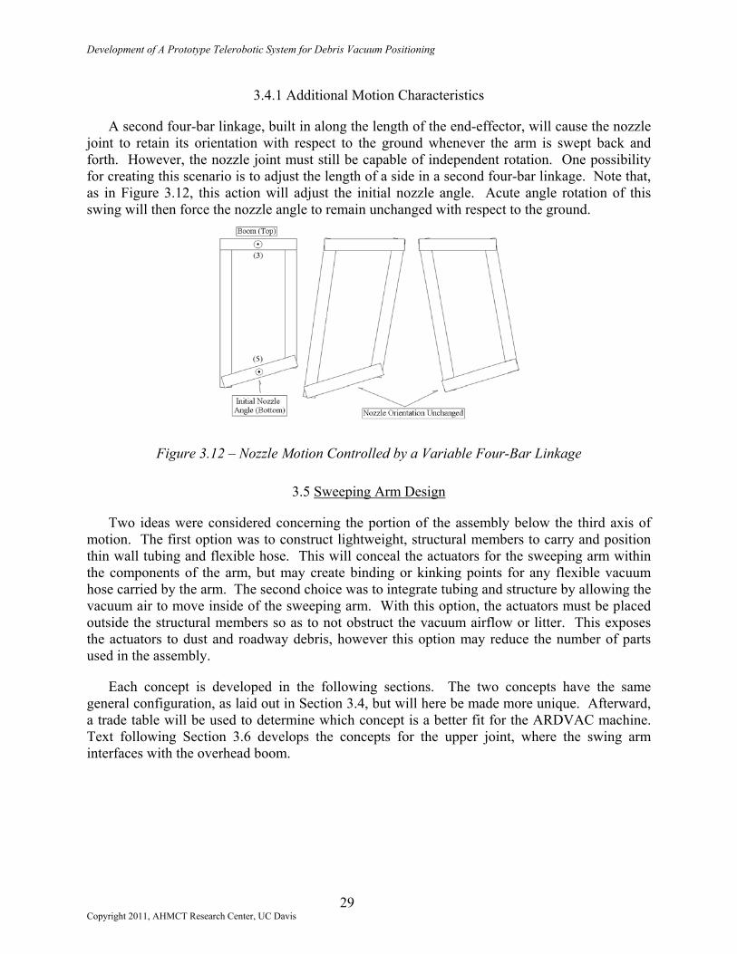
Development of A Prototype Telerobotic System for Debris Vacuum Positioning
3.4.1 Additional Motion Characteristics
A second four-bar linkage, built in along the length of the end-effector, will cause the nozzle joint to retain its orientation with respect to the ground whenever the arm is swept back and forth. However, the nozzle joint must still be capable of independent rotation. One possibility for creating this scenario is to adjust the length of a side in a second four-bar linkage. Note that, as in Figure 3.12, this action will adjust the initial nozzle angle. Acute angle rotation of this swing will then force the nozzle angle to remain unchanged with respect to the ground.
Figure 3.12 – Nozzle Motion Controlled by a Variable Four-Bar Linkage
3.5 Sweeping Arm Design
Two ideas were considered concerning the portion of the assembly below the third axis of motion. The first option was to construct lightweight, structural members to carry and position thin wall tubing and flexible hose. This will conceal the actuators for the sweeping arm within the components of the arm, but may create binding or kinking points for any flexible vacuum hose carried by the arm. The second choice was to integrate tubing and structure by allowing the vacuum air to move inside of the sweeping arm. With this option, the actuators must be placed outside the structural members so as to not obstruct the vacuum airflow or litter. This exposes the actuators to dust and roadway debris, however this option may reduce the number of parts used in the assembly.
Each concept is developed in the following sections. The two concepts have the same general configuration, as laid out in Section 3.4, but will here be made more unique. Afterward, a trade table will be used to determine which concept is a better fit for the ARDVAC machine. Text following Section 3.6 develops the concepts for the upper joint, where the swing arm interfaces with the overhead boom.
29 Copyright 2011, AHMCT Research Center, UC Davis

Development of A Prototype Telerobotic System for Debris Vacuum Positioning
3.5.1 Tube Carrying End-Effector
3.5.1.1 Structural System Carries Vacuum Hose
With this option, large diameter, thin wall tubing would be fixed to all non-rotating and non-telescoping portions of the end-effector structure. Flexible tubing may then be used in places where bending or telescoping are necessary to form one continuous length of vacuum tubing from the nozzle, up the length of the end-effector, along the top of the boom, and into the debris storage bin.
The thin wall tubing or flexible hose material carried along the telescopic sweeping arm will need to change length with the arm. If thin wall tubing is used, one tube can sleeve inside a second of nearly equal diameter. Some large diameter flexible hose materials are capable of expanding in an accordion style, but may not easily stretch the full 0.6 m (24 in) required of the telescoping arm.
3.5.1.2 Hose Buckling
Figure 3.13 shows vacuum tubing fixed both atop the boom and to the face of the end-effector, with an elbow of flexible hose making the connection between the two tubes. Whenever the boom is rotated away from the vehicle’s centerline, the four-bar linkage between the vehicle and the end of the boom will cause the end-effector to rotate about the second axis of motion. This rotation develops a torque on the flexible hose along the second axis, depicted in Figure 3.13(a), and may cause buckling where the elbow meets the horizontal hose. This will distort the hose’s circular cross-section and adversely affect the internal airflow.
Figure 3.13 – Movement of Rotation Centerline; (a) Initial; (b) Revised
To alleviate this, the centerline of the vertical hose can be oriented along the second axis of motion. The addition of a rotational joint to the hose at the bottom end of the elbow will ensure that no torque develops on the hose. Figure 3.13(b) shows how the end-effector assembly must be offset from the vertical axis centerline to accommodate routing of the hose. This new
30 Copyright 2011, AHMCT Research Center, UC Davis

Development of A Prototype Telerobotic System for Debris Vacuum Positioning
configuration allows the vertical length of tubing to remain fixed to and rotate with the end-effector, while the horizontal length of tubing, including the elbow shown in Figure 3.13, remains attached to and rotates with the boom.
3.5.1.3 Sweep Arm Telescopic Extension
Thin wall, square or rectangular box steel will make up the structure of the sweeping arm. The lower or fly section will sleeve up into the larger base section. Each section must be sufficiently long to account for the 0.6 m (24 in) required extension plus adequate overlap to support a cantilevered, fully extended fly. A linear hydraulic cylinder attached between the base and fly, as in Figure 3.14, will control fly extension.
Figure 3.14 – Attachment of the Fly Actuator
The fly must easily slide in and out of the base. This is readily accomplished by fastening journal rollers to the bottom end of the base, and an appropriate roller track to the fly. The track and rollers, a sample of which is sketched in Figure 3.15, work like a desk drawer; the extended portion of the track and the load it carries are cantilevered beyond the journals. This assembly will slide easily and, depending on the product, can carry large loads.
Figure 3.15 – Sample Track and Journal Rollers
3.5.1.4 Nozzle End
Section 3.2.1.5 stated that the nozzle would not be automated. The nozzle design remains straightforward with the exception of a tooth-like feature to prevent the nozzle from drawing itself into the ground under action of the vacuum. This feature permits airflow to continue even while the nozzle is in contact with the ground, thus making it easier to lift the nozzle from the ground. The top of the nozzle, as sketched in Figure 3.16, will be attached to the nozzle bracket,
31 Copyright 2011, AHMCT Research Center, UC Davis

Development of A Prototype Telerobotic System for Debris Vacuum Positioning
discussed in Section 3.5.1.5. The nozzle piece is free to rotate about the end of the sweeping arm, independent of the sweeping arm angle, when moved by the nozzle bracket.
Figure 3.16 – The Vacuum Nozzle
3.5.1.5 Nozzle Bracket
The nozzle bracket supports the nozzle and is attached to the end of the sweeping arm. It is able to spin along the fifth axis when actuated by a hydraulic cylinder. Flexible hose will connect the top ring of the bracket to the bottom of the tubing on the face of the end-effector. To permit smooth bending of the flexible hose as the nozzle bracket is made to rotate, the point of attachment for the hose will be offset from the line of rotation. Without this offset, the hose may be pinched and buckle as the nozzle is rotated. The hose bend in Figure 3.17(a) is not practical. Comparatively, the smoothly curved hose of Figure 3.17(c) is most ideal to avoid obstructing airflow inside the hose.
The simple nozzle ring frame shown at the bottom of Figure 3.11 is modified to accommodate the offset required for smooth hose bending. Figure 3.18 shows the end of the sweep arm with a sketch of the new nozzle bracket. The hose and nozzle rings permit attachment of the respective parts.
Figure 3.17 – Hose Bending with Nozzle Rotation
32 Copyright 2011, AHMCT Research Center, UC Davis

Development of A Prototype Telerobotic System for Debris Vacuum Positioning
Figure 3.18 – The Nozzle Bracket Concept
3.5.1.6 Nozzle Bracket Actuation
The nozzle bracket can be actuated using one of two methods. The first method involves pining a hydraulic cylinder within the fly of the sweep arm and linking it to the bracket via a short lever arm, as suggested by Figure 3.19. The hydraulic hoses leading to the actuator must be guided in and out of the sweep arm as the fly telescopes to avoid becoming crimped or wedged in the sliding joint. Placement of the actuator at the end of the sweep arm shifts mass away from the sweep arm’s point of rotation, and may become an issue in sizing and selecting an actuator to swing the arm.
Figure 3.19 – Cylinder and Attachment to Nozzle Bracket
To eliminate hose routing problems, a second option involves placing the bracket actuator in the upper portion or base of the swing arm, nearer to the arm’s point of rotation. An adjustable length linkage would be required to maintain the connection between the actuator and bracket as the arm telescopes. Neither design takes into account the requirement of Section 3.4.1 for the adjustable four-bar linkage motion of the nozzle. An alternative is developed in the next section that eliminates these issues and incorporates the four-bar nozzle motion requirements.
33 Copyright 2011, AHMCT Research Center, UC Davis

Development of A Prototype Telerobotic System for Debris Vacuum Positioning
3.5.1.7 Combination of Telescope and Nozzle Bracket Actuators
Several design headaches can be cured if two equally sized hydraulic cylinders, properly configured, are used to perform the duties of the telescope and nozzle bracket actuators. The tops of these cylinders are mounted at the same level as the sweeping arm’s point of rotation. The bottoms of these cylinders are then attached to a symmetric flange on the nozzle bracket, as shown in the cross-sections of the sweeping arm, Figure 3.20. The shaft to which the nozzle bracket flange is attached (see Figure 3.19) runs through the bottom of the fly section. Upward support of this shaft from the cylinders will lift the fly and prevent it from sliding out of the base.
Figure 3.20 – Action of Parallel Cylinders Inside Sweep Arm
Simultaneous extension or retraction of these cylinders causes the fly to telescope. Moving the cylinders in opposite directions at the same rate will rotate the nozzle bracket without changing the fly extension. Additionally, having the cylinders’ axes of rotation established in this manner creates the four-bar linkage required in Section 3.4.1. Sweeping the arm without adjusting the length of either cylinder will maintain the nozzle bracket’s orientation with respect to the ground. Note that hose crimping is no longer an issue as the cylinders do not travel up and down within the base or fly.
3.5.2 Integrated Vacuum Tube Concept
The second general sweeping arm idea involves integrating the vacuum tubing and structure of the end-effector. Litter would actually pass inside the sweeping arm on its way into the overhead boom. This option nearly eliminates the need for flexible tubing, and therefore reduces the possibility of hose buckling. The structure of the sweep arm will be made up of thin wall circular steel to provide the vacuum air and litter with a smooth tube path to follow. Features of this design are similar to those of the tube-carrying concept, with the exception of changes listed in the following sections.
34 Copyright 2011, AHMCT Research Center, UC Davis

Development of A Prototype Telerobotic System for Debris Vacuum Positioning
3.5.2.1 External Actuators
Other than being moved outside of the sweep arm, the hydraulic actuators used to extend the fly and rotate the nozzle bracket are set up as described in Section 3.5.1.7. They retain their four-bar configuration and will operate as previously described.
3.5.2.2 Vacuum Seal between the Fly and Base
The fly will slide in and out of the base with a track and journal rollers as described in Section 3.5.1.3. However, because it is now important to maintain a vacuum within the sweep arm, a durable vacuum seal is required between the outer surface of the fly, and the inner surface of the base. This seal will prevent air from being drawn into the gap around the fly.
This seal could be placed at the top of the fly and slide along the interior of the base during extension as in Figure 3.21(a). This leaves the rollers exposed to the atmosphere and any dust that might be kicked into the space between the base and fly. An alternative is to fix the seal to the end of the base and allow it to slide along the side of the fly. Shown in Figure 3.21(b), this option requires that the vacuum seal be maintained around the track as the fly passes into and out of the base. Plastic cap seals meant to protect the rollers are available to keep dust off the rollers and track, and will likely promote selection of the first vacuum seal option.
3.5.2.3 Modified Nozzle Bracket
The shape of the nozzle remains unchanged from earlier, and the nozzle bracket is still required to support the nozzle at a distance below the bracket’s rotational axis. However, the nozzle must now line up beneath the sweep arm as opposed to just forward of it as in Figure 3.18. The vacuum airflow is least impeded when the flexible hose bends smoothly, so attachment of the nozzle to the bracket changes slightly to allow the hose to find its own curvature. Here the nozzle is free to pivot at the end of the bracket based on tension in the flexible hose. Figure 3.22 shows the new bracket and the likely hose attachment method.
Figure 3.21 – Sweep Arm Vacuum Seal Options
35 Copyright 2011, AHMCT Research Center, UC Davis

Development of A Prototype Telerobotic System for Debris Vacuum Positioning
Figure 3.22 – Nozzle Bracket for the Integrated Vacuum Tube Concept
3.5.3 Sweep Arm Concept Selection
In order to select a sweep arm concept, key concept selection criteria were weighted from 1 to 10 based on their design importance. Each concept was then rated from 1 to 5 depending on its ability to fulfill the particular criteria. The products of weight factor and rating were summed to determine a total concept value. These values are listed in Table 3.1. The integrated tube and arm concept accrued a greater design value, and will be developed further in Chapter Four.
3.6 Upper Joint and Boom Attachment
The integrated sweeper arm will connect with the overhead boom of the vacuum system through a unique joint. This joint between the boom and sweep arm must permit rotation on several axes and have sufficient compliance within its design to absorb shock loads which the sweep arm may encounter in mild collisions. This link must also allow litter to pass from the sweep arm up into the overhead boom without any loss of vacuum or infringement of vacuum airflow.
3.6.1 Specific Requirements of the Upper joint
3.6.1.1 Space Limitation
Vertical clearance between the ground and the interface to the boom is 2.1 m (84 in). This factor limits the available room for the upper joint assembly once the height of the sweep arm, nozzle bracket, and nozzle are taken into account. The upper joint assembly should be as compact as possible, although it may extend up and around the lip of the boom should it be necessary.
36 Copyright 2011, AHMCT Research Center, UC Davis

Development of A Prototype Telerobotic System for Debris Vacuum Positioning
weight factor
GENERAL REQUIREMENTSCompatable w/ overhead boom N/A YES YESField servicable N/A YES YESFits general design of sweep arm N/A YES YESImproves operator saftey N/A YES YESLimited access to moving parts N/A YES YESNo patent infringement N/A YES YES
Weighted WeightedSELECTION CRITERIA Rating Score Rating ScoreCan telescope required length 2 5 10 5 10Durability 6 2 12 4 24Increases nozzle access area 10 5 50 5 50Minimum actuators & parts 9 2 18 4 36Minimum cost 3 2 6 3 9Minimum vehicle interfaces 5 4 20 4 20Minimum weight 8 2 16 3 24Positive debris collection 10 5 50 5 50Resistance to mild collisons 4 2 8 3 12Weatherproof / debris resistant 1 2 2 4 4Zero manual set-up time 7 5 35 5 35
TOTALS 227 274RANK 2 1
Integrated Tube & ArmTube Carrying Arm
CONCEPTS
Table 3.1 – Sweep Arm Concept Trade Table
3.6.1.2 Rotation of the End-Effector with the Overhead Boom
As described in Section 3.3.2, the end-effector must always point forward, rotating along the second axis of motion at the boom connection as the position of the overhead boom is adjusted. A low friction rolling or sliding connection within the upper joint should allow it to rotate on a vertical axis at the end of the boom.
3.6.1.3 Sweep Motion and Actuator Mounts
The upper joint must support the weight of the sweep arm and several actuators while allowing the sweep arm assembly to swing beneath the boom. A total of three hydraulic actuators will be used to actuate the sweep motion of the arm, extension of the fly, and rotation of the nozzle. Appropriate mounts for these actuators are required on the upper joint assembly. The centerline of the mounts for the extension and nozzle angle cylinders must be at the same elevation as the sweep arm mount to ensure operation of the four-bar linkage to the nozzle. Placement of the actuator that will swing the sweep arm is dependent on the size of the actuator, and will be determined in Chapter Four. Mounts for the sweep arm should not interfere with the vacuum airflow or arm swinging motions.
37 Copyright 2011, AHMCT Research Center, UC Davis

Development of A Prototype Telerobotic System for Debris Vacuum Positioning
3.6.1.4 Upper Joint Compliance
Breaking the end-effector off of the overhead boom is an undesirable situation. To avoid this, and prevent damaging the boom and truck in situations where the end-effector collides with a stationary object, the upper joint shall incorporate compliance in the form of springs or dampers to absorb the energy of a collision. This system needs to be reusable and realign itself after the impact, without the aid of active controls. The stiffness of this joint must be sufficient to not break free during normal sweep arm use.
3.6.1.5 Upper Joint Vacuum Seal
A vacuum must be maintained between the top of the sweep arm and the opening at the end of the boom throughout all motions of the upper joint. The form of this feature is dependent on the design of the upper joint, but must not obstruct vacuum airflow before, during, or after position adjustments of the sweep arm.
3.6.2 Conceptualization of the Upper Joint
The design of the upper joint was initially inspired by a unique ball-and-socket joint produced by the Leach Company. This joint, shown in Figure 3.23, is meant to connect large diameter tubing to the Vac/All debris body. This assembly contains no special seals or bearings. The interiors of the rolled, bowl-like surfaces mate fairly smoothly and produce a sufficient vacuum seal as the joint is manipulated.
Figure 3.23 – The Leach Tube Ball Joint
3.6.2.1 The Bowl Concept
Although similar in appearance to the Leach universal joint, this concept permits full motion of the sweep arm, has room to attach cylinders, and should absorb small shock loads. The cross-section of the joint in Figure 3.24 shows the sweep arm (base and fly) supported at the bottom of the joint, within the bowl insert. The bowl insert rests at the bottom of the contoured interior of the bowl. A ring tab attached to the circumference of the bowl insert is sandwiched between plastic slip rings and prevents the insert from falling out. The rings and tab are held in place by
38 Copyright 2011, AHMCT Research Center, UC Davis

Development of A Prototype Telerobotic System for Debris Vacuum Positioning
the compression springs, which themselves are spaced evenly about the circumference of the bowl. The sweep arm can rotate freely about the third axis of motion.
The slip rings permit the bowl insert and tabs to rotate about the second axis of motion without loss of the vacuum seal. The flexible hose maintains the vacuum between the top of the base and the top of the bowl assembly, where the joint connects to the boom. When the end of the sweep arm encounters a fixed object, the moment on the sweep arm is transmitted up to the bowl insert and will shift the insert up on one side. This will further compress some of the springs and absorb the energy of the collision. Displacement of the bowl insert, ring tab, and slip rings temporarily breaks the vacuum seal. The curved interior of the bowl then aids the insert in sliding back into alignment after a collision, re-establishing the vacuum seal.
Figure 3.24 – The Spring Loaded Bowl Concept
Figure 3.25 – Bowl Insert Shifted During a Sweep Arm Collision
This concept carries with it few uncertainties. Stiction between the slip rings and contoured bowl may occasionally prevent re-alignment of the bowl insert after a collision. When designed for adequate spring stiffness and displacement, this design may be prohibitively tall, extending beyond the vertical space limitations. Friction forces between the slip rings and ring tab may prevent smooth rotation of the insert along the second axis of motion. Finally, the cylinder mounts may interfere with the bottom of the bowl as the assembly shifts during a collision.
39 Copyright 2011, AHMCT Research Center, UC Davis

Development of A Prototype Telerobotic System for Debris Vacuum Positioning
3.6.2.2 The Dual Tray Concept
To overcome the problems of the bowl concept, the connections to the overhead boom and the sweep arm will be made through two separate sub-assemblies. Figure 3.26 shows a cross-section of the dual tray concept in its normal position. The top tray can manage boom end rotations along the second axis of motion while supporting the weight of the end-effector on the lip at the end of the boom. Stiction problems should be eliminated through the use of roller bearings instead of sliding plastic rings. The bottom tray supports the sweep arm and all actuators, leaving plenty of room for all items to swing as necessary.
Figure 3.26 - The Dual Tray Concept
The two trays are connected by a combination of bolts and springs. Under normal circumstances, the bolts carry the weight of the lower tray. The flexible hose between the top of the base and the flange of the upper tray rotates about the second axis of motion with the end-effector. Thin rubber or felt vacuum seals could then be used around the interior of the upper tray to maintain a vacuum seal and maintain alignment of the upper tray with the lip at the boom’s end.
If the end of the sweep arm collides with a fixed object, the moment on the arm is transmitted through the lower tray and into the compression springs that line the circumference of the upper joint assembly. The springs are pre-loaded so that the assembly will not shift unless a collision occurs, and to aid in re-alignment after a collision. Figure 3.27 shows a cross-section of the dual tray assembly shifted during a sweep arm collision. By allowing the compression springs to extend above the boom lip, larger springs can be used than might fit into the bowl of the previous concept, thus increasing the energy absorbing capacity of the joint. This concept should provide adequate upper joint compliance and permit the sweep arm to move through its entire intended range of motion without compromising the vacuum seal.
40 Copyright 2011, AHMCT Research Center, UC Davis

Development of A Prototype Telerobotic System for Debris Vacuum Positioning
Figure 3.27 – Dual Tray Assembly Shifted During a Sweep Arm Collision
3.7 Summary
This chapter covered the development of concepts for the end-effector. It was decided that no specialty nozzles would be utilized at this time because of the vacuum flow rates on the culvert cleaning machine. The general form and specific requirements of the end-effector were laid out before concepts were developed. Within separate sections of the chapter, several unique ideas for the sweeping arm and upper joint were described. Selection of the integrated vacuum tube sweep arm and dual tray upper joint was based on the perceived advantages of these concepts. This combination will direct the vacuum airflow from litter piles up into the overhead boom, conveying litter into the debris storage bin. Detailed design of the components of the end-effector are found in Chapter Four.
41 Copyright 2011, AHMCT Research Center, UC Davis

Development of A Prototype Telerobotic System for Debris Vacuum Positioning
( This page is intentionally left blank. )
42 Copyright 2011, AHMCT Research Center, UC Davis

Development of A Prototype Telerobotic System for Debris Vacuum Positioning
CHAPTER 4 DETAILED DESIGN OF THE HOSE POSITIONING SYSTEM
4.1 Introduction
The form and function of end-effector components is to manipulate a large diameter vacuum nozzle based on concepts developed in Chapter Three. Design details are included in this chapter, not necessarily in the order of their original conception. The successful design of mutually dependent components of the sweep arm is the result of an iterative process that began with the general idea of partially automating the roadway litter vacuum process.
4.2 End-Effector Sub-Assemblies
The fully assembled end-effector in Figure 4.1 is shown integrated onto the Leach Vac/All Engineering Unit. Components of the hose positioning system are hereafter described from the top of this assembly, downward through each sub-assembly, and concluded with details of the hydraulics that enable motion in this system.
The Upper Joint is the interface point between the body of the end-effector and the end of the vehicle’s overhead boom. It attaches to the lip at the end of the boom and has provisions to mount remaining end-effector components and the three hydraulic cylinders. The Upper Joint consists of an Upper and Lower Tray, the union of which provides a degree of compliance for this assembly. Flexible vacuum hose within the Upper Joint connects the boom opening to the top of the Base.
The Base is a long cylindrical structure that supports cantilever moments as the Fly is extended and is an integral part of the vacuum air pathway. The Base is the uppermost element of the end-effector that is made to sweep back and forth during device operation by the short stroke cylinder attached to the Upper Joint.
The Fly is a large diameter steel tube, capable of extending from and retracting into the Base, to change the ground clearance of the end-effector. The nozzle bracket and nozzle hang from the Fly, and the extension of these components is controlled by simultaneous extension of the twin long-stroke cylinders hanging from the Upper Joint. The vacuum air pathway reaches from the Base through the length of the Fly.
43 Copyright 2011, AHMCT Research Center, UC Davis

Development of A Prototype Telerobotic System for Debris Vacuum Positioning
y
e
Figure 4.1 – The Fully Assembled End-E
The Nozzle Bracket and Nozzle extend the reach of thedevice’s accessibility to litter on the roadway. These elements the fly through opposed motion of the twin long-stroke cylinconnects the bottom of the Fly to the top of the Nozzle. The Nozend-effector, and the first element to come in contact with roadw
4.3 Upper Joint
The combination of the Upper and Lower Trays forms theserves several supportive and motional purposes. The complianboom end lip and functions to support the end-effector whiunderneath the boom lip. The Upper Joint permits unrestrictedthird axes of motion prescribed in Chapter Three.
4.3.1 Upper Tray
The Upper Tray consists of two half circular symmetric secwith various geometries of 0.49 cm (0.19 in) flat steel plate. Inweldment resembles a “C” shaped channel with attached flange,
44 Copyright 2011, AHMCT Research Center, UC Davis
Overhead Boom
Upper Tray
f
ecadez
ay
Ut jle
ti
g
Lower Tra
Hose
BaseShort Cylinder
Fly
t
Nozzle BrackeNozzl
Hose
Long Cylinders
fector
nd-effector and increase the n be rotated about the end of rs. A flexible vacuum hose le is the lowest element on the debris.
pper Joint. The Upper Joint oint hangs from the top of the maintaining a vacuum seal rotation along the second and
ons, as in Figure 4.2, built up cross-section, a portion of the usset, and spring boss, as seen

Development of A Prototype Telerobotic System for Debris Vacuum Positioning
in Figure 4.3. Two Upper Tray weldments fit around the boom end lip and the weight of the assembly is supported on the lip with 1.9 cm (0.75 in) diameter Delrin (thermoplastic) ball bearings, spaced evenly around the circumference of the lip by 1.6 cm (0.63 in) square Delrin bar material cut into trapezoidal shapes. Delrin is used in place of steel to avoid the need for lubrication and eliminate rust or corrosion worries should water enter the channel. The 31 cm (12 in) outer diameter of the retaining ring serves as a connecting surface for the flexible vacuum hose that will maintain the vacuum airflow between the boom and the top of the Base.
Figure 4.2 – An Upper Tray Weldment
l
Figure 4.3 – Channel of an Upper Tr
4.3.1.1 Split Sections Simplify Boom Attachment
The nature of the boom lip prevents a closed section fromfrom below the lip. The symmetric Upper Tray halves sohowever, makes placement of the Delrin roller bearings difficube placed behind the retaining ring, in the channel, and preveoff the openings with paper and tape. The top set of bearingpaper retaining ring that is taped to the outside edge of the booas the split rings are being assembled.
45 Copyright 2011, AHMCT Research Center, UC Davis
Interior Channe
Retaining Ring
ay Half
being slipped up on to the boom lve this problem. This design, lt. The lower set of bearings can
nted from rolling out by blocking s must be set inside a sacrificial m lip so that they will not fall out

Development of A Prototype Telerobotic System for Debris Vacuum Positioning
Figure 4.4 – Lower Delrin Balls and Spacers in Upper Tray Channel
Figure 4.4 shows the placement of some of the Delrin bearings in an Upper Tray half. This joint will rotate at very slow speeds, and during irregular intervals. Because of this, there is little concern about wear or binding of the balls or spacers within the Upper Tray channels. The two channel halves slip over the boom end lip and top set of balls in order to join the open channel ends. The paper used to retain the lower balls in the channel is slipped out of the mating faces before fasteners are used to hold the two sections together. Figure 4.5 depicts the before and after assembly views of the symmetric Upper Tray halves.
(a) (b)
Figure 4.5 – Upper Tray: (a) Split Halves, (b) Assembled on Boom
4.3.1.2 Vertical Axis Rotation
The presence of the Delrin balls permits the assembled Upper Tray halves to rotate along the second axis at the boom’s end. This feature is not used on the Engineering Unit Vac/All due to its fixed overhead boom, but is required for the articulated boom. The top set of Delrin balls roll against the top inner surfaces of the channel, supporting the weight of the end-effector. The lower Delrin balls then aid in maintaining the Upper Tray’s vertical position with respect to the boom lip, especially in cases where the end-effector strikes a fixed object, transmitting loads
46 Copyright 2011, AHMCT Research Center, UC Davis

Development of A Prototype Telerobotic System for Debris Vacuum Positioning
through the springs and into the boom. The springs and compliance of the Upper Joint are discussed in Section 4.3.3. The tall circumferential retaining ring welded to the bottom of the channel acts as to keep the lower Delrin balls in place.
4.3.1.3 Boom Vacuum Seal
Adhesive backed felt, applied to the top of the retaining ring, ensures a good seal between the boom vacuum opening and the flexible hose. When assembled on the truck, the top of the retaining ring sits 0.95 cm (0.375 in) below the boom lip. The felt material rubs the lower surface of the boom and maintains a vacuum seal as the Upper Tray is made to rotate on the boom end lip.
4.3.1.4 Spring and Bolt Interface
The 52 cm (21 in) outer diameter top plate of the Upper Tray has 12 spring bosses welded to its underside. Coaxial with these bosses are 1.6 cm (0.63 in) holes through which pass the 1.3 cm (0.5 in) diameter long bolts that will support the Lower Tray. The bolts must be able to shift within the holes in the case where the end-effector collides with a fixed object, causing the Lower Tray to tilt with respect to the Upper Tray. The two trays normally remain parallel to one another. Gussets between the top plate and vertical exterior wall of the Upper Tray help transition the weight of the end-effector to the channels of the Upper tray. Figure 4.6 points out these elements.
The Lis necessthe compactuationconcentrboth throweldmen
Copyright 20
Gussets
Spring Boss
Figure 4.6 – Upper Tray showing Gussets and Spring Bosses
4.3.2 Lower Tray
ower Tray, shown in Figure 4.7, supports the Base and allows it to swing. Its large size ary to permit centerline clearance of the flexible vacuum hose, and to accept and support ression springs that fit on the Upper Tray. The lower tray has mounts for hanging all cylinders and the base tube itself. There are counter bores to accept the springs and ic holes through which pass the long mounting bolts. A plethora of additional holes, ugh and blind, are drilled into the Lower Tray to aid in weight reduction of this t.
47 11, AHMCT Research Center, UC Davis

Development of A Prototype Telerobotic System for Debris Vacuum Positioning
4.3.2.1 Flex Hose Clearance
The 39 cm (15 in) diameter oval opening in the center of the Lower Tray permits passage of the flexible tube between the bottom of the Upper Tray and the top of the Base. The long axis of this oval is noticeably larger than the diameter of the flexible hose. This clearance is necessary to permit bending of the hose along the long axis as the Base swings underneath, in a plane centered between the flanges.
Figure 4.7 – The Lower Tray Weldment
4.3.2.2 Spring and Bolt Interface
Counter bored holes in the Lower Tray accept the compression springs mentioned in Section 4.3.1.4. The long bolts that passed through the Upper Tray continue downward through the compression springs and through 1.6 cm (0.63 in) holes in the Lower Tray. The bolts are threaded with Ny-Lock nuts, and the 12 annular bolts carry the weight of the Lower Tray plus the pre-load force on the springs. Note that in cases where the Lower Tray shifts upward with respect to the Upper Tray, the tensile load on a portion of the bolts will be temporarily removed until the springs return the system to its normal state. This required the use of the Ny-Lock nuts to prevent a fastener from making its way off a bolt after many vibration cycles. The symmetric counter bores and through holes in the Lower Tray keep the weight relatively low and evenly distributed. These features are pointed out in Figure 4.8.
48 Copyright 2011, AHMCT Research Center, UC Davis

Development of A Prototype Telerobotic System for Debris Vacuum Positioning
Spring Counter Bore
Through Holes
Figure 4.8 – Top View of the Lower Tray
4.3.2.3 Base Mounting
The four wide flanges welded to the underside of the Lower Tray support the Base. The Base is made to swing beneath the Upper Joint, hence the alignment of holes in the flanges designed to accept brass sleeve bushings and swing pins. The bushings are used to reduce wear on the steel flanges. The 1.9 cm (0.75 in) diameter holes in the flanges accept press fit bushings that reduce the hole diameters to 1.6 cm (0.63 in). Two stainless steel pins are then used to support the Base. These pins are fitted with grease caps, drilled, and turned to form grease pathways that will aid in lubricating these rotating joints. The pins have factors of safety near 33. Shaft collars, having been welded to the outermost flanges, provide setscrews that secure the pins in place.
Figure 4.9 shows the Base support flanges on the lower tray, while Figure 4.10 shows the swing pins. The Base is free to rotate on the pins; the turned grease path on the pins aligns with and lubricates the brass bushings installed in the Base crowns (see Section 4.4.2).
49 Copyright 2011, AHMCT Research Center, UC Davis

Development of A Prototype Telerobotic System for Debris Vacuum Positioning
Long Cylinder Supports
Short Cylinder Support
Pin joint & Shaft Collar
Flanges
Figure 4.9 – Support Flanges
h Grease Fitting
4.3.2.4
ThrTray. Tcm (0.8cm (0.7and selassemb
Copyright
Turned Grease Pat
Figure 4.10 – Swing Pins
Cylinder Mounting
ee additional flanges, visible in Figure 4.9, are also welded to the underside of the Lower he 4.1 cm (1.6 in) wide flange supports the short cylinder for Base swing motion. Its 2.2 8 in) diameter through hole accepts a press-fit brass bushing that will hold the greased 1.9 5 in) diameter top pin of the short cylinder. This pin is supplied with the cylinder. Sizing ection of this cylinder are specified in Section 4.8.2. Figure 4.11 shows the short cylinder led on the end-effector, hanging from the wide flange of the Lower Tray.
50 2011, AHMCT Research Center, UC Davis

Development of A Prototype Telerobotic System for Debris Vacuum Positioning
The two 3.2 cdiameter through htop pins of the shsupport flange arethe long-stroke cyBracket. A mounremainder of the lThree, where opeNozzle Bracket ro
In the event thof impact loadingbetween the Uppemotion between thin Figure 4.12, wunder normal end-
Copyright 2011, AHMCT R
Flange
Figure 4.11 – Short Cylinder and Mount Flange
m (1.3 in) wide flanges support the long cylinders. The 1.6 cm (0.63 in) oles accept press-fit brass bushings that hold greased 1.3 cm (0.5 in) diameter
ort cylinders. Note that the holes in the narrow flanges and in the rear Base coplanar and symmetric about the Lower Tray’s centerline. This placement of linder mounts develops the top end of a four-bar linkage with the Nozzle
ting flange on the Bracket and the long-stroke cylinders themselves create the inkage. Specification and operation of this linkage was described in Chapter ration of the long cylinders was said to permit Fly extension, retraction, and tation.
4.3.3 Upper Joint Compliance
at the end-effector strikes a fixed object, it is desirable to dissipate the energy through a compliant element of the device. The compression springs fitted r and Lower Trays of the Upper Joint serve this need. They permit relative e two Trays that are normally held parallel to one another. The springs, shown ere pre-loaded to prevent unwanted motion and vibration of the Upper Joint effector operation circumstances.
51 esearch Center, UC Davis

Development of A Prototype Telerobotic System for Debris Vacuum Positioning
Long Bolts CompressionSprings
Figure 4.12 – The Springs of the Upper Joint
Impact or excessive static loads imparted to the swinging portion of the end-effector will be transmitted through the body of the end-effector and into the Lower Tray. Compression of a number of the springs will then prevent these forces from being transmitted into the overhead boom. When the load is removed, the device will reset itself as the springs expand until the Lower Tray is again constrained against the Ny-Lock nuts threaded onto the bolts.
The number, size, and pre-load of the springs used depended on the estimated overload or impact force that might be experienced should the end-effector strike a fixed object. The springs have to be fairly long to achieve appreciable forces when compressed, and hence motion in the Upper Joint. The springs would also have to be of minimum outer diameter to prevent creating an Upper Joint that was significantly wider than the overhead boom tube. The overload value was initially assumed to be 445 N (100 lbs) at the end of the nozzle with a fully extended Fly. After iterating to select appropriate springs, threshold values for disrupting the set of the Upper Joint were determined. With the Fly fully extended, the application of roughly 329 N (74 lbs) at the end-effector’s extremity should cause motion in the Upper Joint. This load increases linearly to 449 N (101 lbs) at the Nozzle end as the Fly is made to fully retract.
4.4 Base Design
The Base tube is a large diameter, rigid open tube that supports the cantilevered Fly (when the end-effector is swept to one side) and permits vacuum airflow through its interior without being unreasonably heavy. The 33 cm (13 in) outer diameter of the Base was selected in conjunction with the dimensions of the Fly tube (see Section 4.5). The Fly and its roller track accessories required sufficient clearance inside the Base to permit telescopic motion, without the final assembly becoming so large as to block the vehicle driver’s view of the road when mounted to the truck. The Base accepts flexible vacuum hose with a 30.5 cm (12 in) inner diameter at its top, and has provisions to mount journal rollers that support the Fly’s roller track. Figure 4.13 shows the Base weldment.
52 Copyright 2011, AHMCT Research Center, UC Davis

Development of A Prototype Telerobotic System for Debris Vacuum Positioning
Figure 4.13 – The Base Weldment with attached accessories
4.4.1 Shaping the Base
Elements of the Base are depicted in Figure 4.14. 33 cm (13 in) diameter tubing is not a stock size. The tube portion of the Base is therefore fabricated from 12-gage sheet metal rolled to the correct size and welded along the seam. The long, narrow channels fulfill two roles; 1) They provide clearance for the roller track attached to the Fly as it is made to retract into the Base, 2) They provide structure to support the bending moment that rotates the Base and swings the end-effector below the Upper Joint. The shorter, wider channels are the mounting platforms for the roller journals and cap seals that clean the roller track.
Both sets of channels are formed from 0.48 cm (.188 in) sheet metal that is rolled to shape. The long channels are 7 cm (2.8 in) wide and 58 cm (23 in) long. The short channels are 17 cm (6.8 in) wide and 28 cm (11 in) long. The channels are welded to the Base after portions of the tubing are cut away; the interior volume of the Base then includes the inside of the tube and all four channels.
53 Copyright 2011, AHMCT Research Center, UC Davis

Development of A Prototype Telerobotic System for Debris Vacuum Positioning
Flex Hose Attach
LONG Channel
Rings
The 8 rincircularity. transitional rhose attachmor the crownfinal end-effmaintain a v(0.13 in) shemore evenly
Copyright 2011, A
Rolled Tube
Short Channel
Figure 4.14 – Features of the Base
gs, cut from 0.48 cm (.188 in) sheet metal, serveThe top tube portion of the Base is an interface fegion of the tube, seen better in Figure 4.15, joent to the 33 cm (13 in) diameter remainder of , at the top of the Base protrude upward above ector assembly, are pinned to the flanges hanginacuum inside the Base, the top ends of the longet metal. Gussets are welded in the pockets bet transition the moment loading between the sectio
Figure 4.15 – Base details: the crown and
54 HMCT Research Center, UC Davis
Crown
W
torinththg c
wen
t
SHORT CYLINDER
t
Gusseeldment
o stiffen the Base and maintain its the top flexible vacuum hose. A s the 31 cm (12 in) diameter flex e Base’s tube. Mounting flanges, e flex tube attachment and, in the from the Lower Tray. In order to hannels are capped with 3.2 mm en the long and short channels to s.
Transition
ub
Crown
e transition

Development of A Prototype Telerobotic System for Debris Vacuum Positioning
4.4.2 The Crown
These two 9.5 cm (3.8 in) wide flanges are welded to the top of each long channel. The rectangular hole in each part was originally intended to aid in weight maintenance of the weldment. The design as it is permits a safety factor of 30. A 1.9 cm (0.75 in) diameter hole in each crown will accept a press fit brass bushing that reduces the opening to a 1.6 cm (0.63 in) diameter hole. The stainless steel swing pins described in Section 4.3.2.3 will support the Base at these bushings. As in the Lower Tray, the bushings will help prolong the life of the holes in the steel by preventing the misshaping of the holes. A close up view of a crown part without a sleeve bushing is shown in Figure 4.15.
4.4.3 Short Cylinder Flange
The triangular flange welded to the face of the front long channel permits attachment of the bottom end of the short cylinder. The flange before and after cylinder attachment is shown in Figure 4.16. Here, forces developed through actuation of the short cylinder are transmitted into the Base, and will cause it to swing beneath the Lower Tray. Like the other pin joints, this one is drilled oversized at 2.2 cm (0.88 in) diameter to accept a press-fit brass bushing. The pin for this joint was supplied with the short cylinder rod clevis, and is well greased before being installed during end-effector assembly. Similar to the crown, this flange was specially shaped and pocketed in an attempt to minimize its weight.
(a) (b)
Figure 4.16 – Base details; the short cylinder flange (a) before and (b) after installation of the short cylinder
4.4.4 Roller Journal & Cap Seal Attachment
Studs on the roller journals fit into the 14 mm (0.55 in) through holes drilled in the short channel sections. The journals have a “V” shaped grove that accepts and supports the Fly via the attached “V” edge roller track. The journal mounting holes are spaced 8.7 cm (3.4 in) apart horizontally on center, and 17 cm (6.8 in) apart vertically, the lower holes being 5 cm (2 in) above the bottom of the channel. The horizontal hole separation is determined by the size of the roller track and journals. The vertical hole separation and journal size is based on a loading equation provided by the journal manufacturer.
55 Copyright 2011, AHMCT Research Center, UC Davis

Development of A Prototype Telerobotic System for Debris Vacuum Positioning
Thin metal washer type shims are used to adjust the spacing between the journals and the interior wall of the short channels. Adjustment of the number of shims assures coaxial alignment of the Fly within the Base. Rubber cap seals, constructed with oil impregnated felt pads, fit over the roller journals. They lubricate and clean the roller track as it is moved and protect the journals from contaminants. According to the manufacturer, use of the cap seals increase journal and track maximum load capacity by a factor of four.
(a) (b)
Figure 4.17 – The short channel; (a) hole pattern, (b) cap seals inside the Base
4.4.5 Hydraulic Manifold Placement
Mounting flanges for the hydraulic manifold were welded to the upper rear of the Base. This places the manifold below the second axis rotation and decreases the number of hydraulic hose lines that will need to regularly bend as the sweep arm is made to move. In this configuration, only the pressure and tank return hydraulic lines that supply the manifold shall have to move with the end-effector. The manifold, with attached flow control valves, solenoids, and wiring junctions, fits neatly between the long stroke cylinders, as seen in Figure 4.18. Two sets of on/off valves control motion of the long cylinders. A set of proportional valves operates the short cylinder via pulse width modulation (PWM) electronics. All end-effector motion is controlled electrically from a multi-function joystick in the cab of the vehicle. Section 4.9 provides more information on the ARDVAC’s first generation control system.
56 Copyright 2011, AHMCT Research Center, UC Davis

Development of A Prototype Telerobotic System for Debris Vacuum Positioning
Valves, Flow Adjust, Solenoids
U
Figure 4.18 – The Hydraulic Ma
4.5 Fly Design
4.5.1 Fly Tube
The Fly is a straight steel tube with a few accessories tmotion into and out of the Base. A 31 cm (12 in) outer diam99 cm (39 in) from stock material. Two 1.9 cm (0.75 in) patterned after holes on “V” edge roller tracks are welded to other. These bars permit mounting of the “V” track to the Flthe Fly for a sliding vacuum seal. Additionally, hardware aFly’s extension and allows for support of the Nozzle Brweldment, with all related accessories attached, is shown in F
57 Copyright 2011, AHMCT Research Center, UC Davis
Supply & Return
Manifold (behind cylinder)
PRESSRE
nifold
hat enable control of its telescopic eter steel tube is cut to a length of
square steel bars with tapped holes the tube diametrically opposite each y. Provisions are made at the top of t the bottom of the Fly controls the acket (see Section 4.6). The Fly igure 4.19.

Development of A Prototype Telerobotic System for Debris Vacuum Positioning
Figure 4.19 – The Fly Weldment with attached accessories
4.5.2 Telescopic Motion
The “V” edge tracks mentioned in Section 4.4.4 roll in special roller journals attached to the base. They are fastened to square bar that has been welded to the tube of the Fly. Telescopic motion of the Fly is controlled by the twin long-stroke cylinders that interface with the bottom of the Fly at the lift pin sleeve (Section 4.5.4.2). Upon retracting into the Base, the tracks fit into the space of the long channels. The tracks are 87 cm (34 in) long and 44 mm (1.7 in) wide, and support the moments developed by the cantilevered Fly as the end-effector is made to sweep back and forth under the overhead boom. The mounting bar and other weldment accessories are pointed out in Figure 4.20.
58 Copyright 2011, AHMCT Research Center, UC Davis

Development of A Prototype Telerobotic System for Debris Vacuum Positioning
“V” Track Attachment
NA
A vacuumoverhead boombetween the toBase as the Flosses throughsection of the another set wip
Two stripsthe Fly. The sthe Fly and tuin) thick felt arinto the long cand wipe the cchannel seal flwhere the “V”
Copyright 2011, AHM
TUBE SEAL
Mounting Bar
ozzle Bracket ttachments
Figure 4.20 – Elements of the Fly weldment
4.5.3 Sealing Method
must be maintained within the Fly and Base for proper debris transport into the . To accomplish this, pairs of vacuum seals were fabricated to close the gap
p of the Fly and the inside of the Base. These seals wipe along the interior of the ly is extended, significantly restricting vacuum airflow and subsequent pressure the channels and around the exterior of the Fly. Because of the awkward cross-Base’s interior, one set of seals wipe along the cylindrical tube of the Base, while es along the interior of the long, narrow channels.
of 3.8 cm (1.5 in) wide, 3.2 mm (0.13 in) thick felt are riveted to the top end of trips start and end just behind the “V” tracks on the Fly, and seal the joint between be portion of the Base. Two shorter strips of 3.2 cm (1.3 in) wide, 3.2 mm (0.13 e riveted to small aluminum flanges that fasten to the top interior of the Fly and fit hannels. The wide “U” shape of the flange and felt sit upright within the channels hannel walls as the Fly is extended. The Fly must be fit into the Base before the anges can be installed, as they will not fit between the roller journals and cap seals track is supported.
59 CT Research Center, UC Davis

Development of A Prototype Telerobotic System for Debris Vacuum Positioning
Channel Seal Flange & Seal
Tube Seals
Top of Fly
Figure 4.21 – The vacuum seals of the Fly
4.5.4 Nozzle Bracket Interface
The weight of the Fly is supported at its bottom end, where a pivotal axis permits rotational motion of the Nozzle Bracket. A stock flange bearing and a fabricated pin sleeve accept a dowel pin and straight lift pin, respectively. These pins together support the Nozzle Bracket, while the lift pin also serves as a connection to the long-stroke cylinders.
4.5.4.1 Dowel Pin Mount
The lower front end of the Fly has two 3/8-16 nuts welded to its exterior face. Here a purchased flange bearing, which includes a bearing surface made of nylon as shown in Figure 4.22(a), is fastened to support the front of the Nozzle Bracket. A dowel pin, such as is featured in Figure 4.22(b), is fit into this flange bearing and fastened to the Nozzle Bracket. The pin is free to rotate in the flange bearing.
(a) (b)
Figure 4.22 – (a) A flange bearing; (b) dowel pins
4.5.4.2 Lift Pin Mount
Features welded to the lower rear end of the Fly support the weight of the Fly and Nozzle Bracket via a 1.9 cm (0.75 in) diameter stainless steel lift pin. The short boss and gussets welded
60 Copyright 2011, AHMCT Research Center, UC Davis

Development of A Prototype Telerobotic System for Debris Vacuum Positioning
to the Fly, shown in Figure 4.23, transmit the lifting force from the pin and long-stroke cylinders into the Fly, thus controlling the Fly’s extension from the Base. The lift pin, featured in Figure 4.24, fits through the top rear bearing of the Nozzle Bracket and into the lift pin sleeve. The pin is held in place by a fastener threaded through the pin sleeve and into a notch in the pin itself.
A 1.1 cm (lift pin. The Npin is drilled abearing and cyand dowel pinstroke cylinder
Copyright 2011, AHM
Fly Tube
t
L
Figure 4.23 – Lift pin sleeve and gus
Gh
Figure 4.24 – Lift pin
0.44 in) thick spacer and the cylinder flange (Sectiozzle Bracket, spacer, and cylinder flange are fr
nd turned to form grease pathways that will aid inlinder flange on the Lift Pin. The pin has a facto
are coaxial and permit the Nozzle Bracket to rotates are actuated opposite to one another. This assem
61 CT Research Center, UC Davis
Gusse
ift pin Sleeve
sets
rease paths
Notcon 4.6.1) slip over the end of the ee to rotate on the lift pin. The lubricating the Nozzle Bracket r of safety near 30. The lift pin about the fifth axis as the long-bly is shown in Figure 4.25.

Development of A Prototype Telerobotic System for Debris Vacuum Positioning
e
Spacer
Fasteners & lock washers
Nozzle Bracket
Figure 4.25 – Explo
4.5.4.3 Lower Flex Hose
The Fly protrudes 3.8 flexible hose material mayThis flexible hose connectstop of the Nozzle.
The Nozzle Bracket sueffector. Shown in Figure by placing a gap between thpassive on the Bracket’s lorotates with respect to the 4.27 depicts this process. minor collisions between thwithout affecting the remBracket’s legs are offset by
Copyright 2011, AHMCT Research Cent
Lift pin
ded view of cylind
cm (1.5 in) beyo be slipped over th and maintains the
4.6 Noz
pports the Nozzle 4.26, the Bracket pe end of the Fly an
wer axis; the stiffnBracket as the BraBy allowing the Ne Nozzle and fixe
ainder of the end 46 cm (18 in).
62er, UC Davis
Cylinder flang
er flange attachment and part orientations
nd these pin mounts so that a second section of e end of the Fly and secured with a hose clamp.
vacuum between the lower end of the Fly and the
zle Bracket
and adds an extra degree of freedom to the end-ermits smooth bending of the lower flexible hose d the top of the Nozzle. Rotation of the Nozzle is ess of the hose will determine how far the Nozzle cket itself is made to rotate under the Fly. Figure ozzle rotation on the Bracket to be passive, many d objects will merely shift the Nozzle on its axis
-effector. The axes of rotation on each of the

Development of A Prototype Telerobotic System for Debris Vacuum Positioning
Figure 4.26 – The Nozzle Bracket Weldment
Flex of hose determines Nozzle rotation amount
Dowel pins & pin bearings
Figure 4.27 – Rotation of the Nozzle Bracket
The Bracket has four pin mount bearings that accept three dowel pins and the cylinder flange. The top dowel and cylinder flange were introduced in Sections 4.5.4 and 4.5.4.2, respectively. The remaining dowels support the Nozzle via flange bearings similar to the one mounted to the Fly. The rolled channels of the Nozzle Bracket permit the rotational moment generated at the cylinder flange to be transmitted around to the forward leg of the Bracket. Both legs of the Bracket then contribute to movement of the Nozzle and flexible hose.
4.6.1 Cylinder Flange
The cylinder flange is the junction between the twin long-stroke cylinders, the Nozzle Bracket, and the Fly. This flange, shown in Figure 4.28, creates the bottom end of a four-bar linkage between the long-stroke cylinders and the mounts welded to the Lower Tray above. Simultaneous extension of the cylinders causes vertical translation of the center point of the flange. This carries with it the lift pin that supports the Bracket and the Fly, thus extending or retracting these elements. Opposed motion of the two long-stroke cylinders causes rotation of
63 Copyright 2011, AHMCT Research Center, UC Davis

Development of A Prototype Telerobotic System for Debris Vacuum Positioning
the flange and holds the vertical position of the lift pin constant. This rotates the Nozzle Bracket while maintaining the current height of the Fly and Nozzle Bracket.
Cylinder pin joint
Lift pin joint
Figure 4.28 – The cylinder flange
The three larger through holes of the cylinder flange have been drilled oversize to accept press fit brass sleeve bushings. The inner hole is 2.2 cm (0.88 in) in diameter, and fits over the lift pin after the bushing is properly placed. The outer holes are each 1.6 cm (0.63 in) in diameter, and will hold the lower pins of the long-stroke cylinders after the correct bushings are press fit to these holes. The pins were supplied with the rod clevis of the long cylinders, and are well greased before assembly. The six 1.0 cm (0.38 in) diameter holes drilled around the center hole permit fastening of the cylinder flange to the largest of the four bearing mounts on the Nozzle Bracket. A 1.1 cm (0.44 in) thick spacer fits between the Bracket and the cylinder flange.
4.6.2 Dowel Pins
These steel pins, shown in Figure 4.22(b), fit through and are fastened to bearings in the Nozzle Bracket. They are fabricated by turning down a solid piece of steel to the correct dimensions on a lathe. This maintains perpendicular alignment between the shaft and the backing plate of the dowel where attempting to weld two separate pieces together may not have done so. When assembled, all three dowels are fixed with respect to the Nozzle Bracket and permit rotation of the Bracket with respect to the Fly, and rotation of the Nozzle with respect to the Bracket. These pins are not greased as all three ride in the nylon portions of the flange bearings on the Fly or Nozzle.
(a) (b)
Figure 4.29 – The Nozzle Bracket showing (a) the lift pin bearing and (b) a dowel bearing
64 Copyright 2011, AHMCT Research Center, UC Davis

Development of A Prototype Telerobotic System for Debris Vacuum Positioning
4.7 Nozzle Design
Chapter Three reviewed options for automated nozzles and came to the conclusion that this iteration of the ARDVAC should have a non-automated nozzle. The performance of the entire hose positioning system will be evaluated in system testing, and the need for a specialized nozzle that may make use of the ARDVAC more affective in particular applications will be decided.
In the mean time, the Nozzle is a short section of thin-walled steel tubing similar in diameter and thickness to that used for the Fly. Shown in Figure 4.30, it has four slits cut into its lower end, each 90 degrees apart, to permit continuous airflow in cases where the nozzle is very near to or on the ground. These slits permit continuous yet reduced vacuum airflow at the Nozzle such that the pressure drop caused by the vacuum cannot hold the Nozzle firmly against the ground. This will short circuit the need to power down the vacuum in order to release the suction that holds the Nozzle to the ground.
Figure 4.30 – The Nozzle Weldment with attached accessories
Two pairs of bolts fixed diametrically opposite each other are welded to this short tube and provide mounting points for additional bearing flanges. These flanges accept the dowel pins that fit through the lower bearings of the Nozzle Bracket. The top portion of the nozzle protrudes 3.8 cm (1.5 in) above the flange bearing mounts, providing a clamping surface for the flexible vacuum tube that attaches to and maintains the vacuum between the bottom of the Fly and the top of the Nozzle. Figure 4.31 points out the slits and bolts.
65 Copyright 2011, AHMCT Research Center, UC Davis

Development of A Prototype Telerobotic System for Debris Vacuum Positioning
Slits in Nozzle
Mounting bolts for flange bearing
Figure 4.31 – Details of the Nozzle Weldment
4.8 Hydraulic Cylinders
4.8.1 Long Stroke Cylinders
The Fly is designed to extend up to 61 cm (24 in) from its fully retracted position within the Base. It was assumed that the long stroke cylinders would carry the vertical weight component of the Fly, Nozzle Bracket, Nozzle, and lower flexible hose. This amounts to a maximum load of roughly 383 N (86 lbs). The long stroke cylinders therefore could have a small bore and rod without sacrificing cylinder strength. Two pneumatic cylinders on hand at the AHMCT Center were converted to hydraulic use for the ARDVAC project. With a 3.8 cm (1.5 in) bore, 1.6 cm (0.63 in) rod, and 61 cm (24 in) stroke, these cylinders fit very well into the space limitations and permit telescopic motion of the Fly without the need for pulleys or linkages to multiply the effect of their stroke.
Hydraulic seal kit conversions permit use of the cylinders with the hydraulic system, but add the requirement that hydraulic oil pressures be maintained at or below 3450 kPa (500 psi). A pressure-regulating valve was installed in the hydraulic circuit that feeds the hydraulic manifold to reduce the hydraulic pressure to the long stroke cylinders. Given the bore and rod diameters, these cylinders remain capable of lifting 3.2 kN (730 lbs) each, more than enough to cope with the items listed above.
At 1 m (40 in), the retracted distance between the long stroke cylinder mounts on the Lower Tray and the cylinder flange was nominally longer than the retracted pin-to- pin length of a long cylinder. To compensate, these cylinders were fitted with rod extensions that increase the long stroke cylinder’s pin-to-pin length by approximately 23 cm (9 in). Shown in Figure 4.32, these extensions are composed of 2.2 cm (0.88 in) diameter steel rod threaded at each end to fit on the existing rod and to accept the rod clevis. The rod end of the extension is necked down to 1.6 cm (0.63 in) diameter just above the threads, and a 1.3 cm (0.5 in) flat wrenching region permits tightening the extension against both the cylinder rod and the rod clevis.
66 Copyright 2011, AHMCT Research Center, UC Davis

Development of A Prototype Telerobotic System for Debris Vacuum Positioning
Wrenching region
Figure 4.32 – Long stroke cylinder rod
Parallel alignment of these cylinders between the Mounts ocylinder flange creates the four-bar linkage specified in Chaptthe Nozzle Bracket to retain its orientation with respect to the gback and forth. The hydraulic conversion kits contained 1.3 cand rod clevises to their respective mounts. Several 0.8 mm (0diameter shims are fit on these pins in within the clevis arms away from the Base as they hang in place. This ensures therethe long cylinders and the Base as the sweep arm moves.
4.8.2 Short Stroke Cylinder
Intended to operate at 17200 kPa (2500 psi), this cylinder pressure level due to the restriction placed on the operation oshort cylinder was selected based on calculated loads, pin plnecessary to swing the sweep arm +/- 30 degrees from the vertbe sufficiently capable of swinging the Base, Fly, Nozzle Brhose beneath the Upper Joint.
An Excel spreadsheet was used to calculate lever arm distathe Base to the line of action of the cylinder at the extremestimated values were compared with off the shelf cylinders avcatalogs. The cylinder was ordered assuming it could handlesystem, but in initial testing would be operated at the lower prelong stroke cylinders. The result a 5.1 cm (2 in) bore, 2.5 cm (cylinder manufactured by Miller Fluid Power.
The orientation of this cylinder places increased loads on thprofile of the end-effector to a minimum. When viewed frotation of the swing arm requires an extension force of 4 kN clockwise rotation, the short cylinder must pull with 4.1 kNpressure settings, this cylinder is capable of exerting 7 kN (1(1178 lbs) in retraction.
67 Copyright 2011, AHMCT Research Center, UC Davis
Rod end
Clevis end
extensions
n the Lower Tray and those on the er Three. This mechanism forces round as the sweep arm is swung m (0.5 in) pins for fixing the cap .03 in) thick, 1.3 cm (0.5 in) inner such that the cylinders are spaced will not be interference between
will also run at a lower hydraulic f the long stroke cylinders. The
acements and the resulting stroke ical. The short cylinder needed to acket, Nozzle, and lower flexible
nces from the point of rotation of es of its range of motion. The ailable in typical hardware supply the full operating pressure of the ssure level established by the two
1 in) rod, 10 cm (4 in) short stroke
e swing pins, but keeps the width rom the front, counterclockwise (888 lbs) in the short cylinder. In
(924 lbs). Even at the lower 571 lbs) in extension and 5.2 kN

Development of A Prototype Telerobotic System for Debris Vacuum Positioning
4.9 Controlling the End-Effector
A three-axis joystick equipped with five trigger switches controls all motion of the end-effector from the cab. The hydraulic valves for both of the long stroke cylinders are of the on-off variety. They are stacked atop flow controlling valves that permit fine-tuning of the hydraulic oil flow rates into both sides of the cylinders. In future applications, these valves may be replaced with proportional controllers. The valve stack for the short stroke cylinder is proportional, and therefore can control sweep arm swing speed. An adjustable pressure bypass valve in this stack allows the short cylinder to move when a threshold load limit is surpassed. This will help prevent system damage in the event that the end-effector should strike a fixed object.
The joystick is shown in Figure 4.33. The X-axis of the joystick (left-right motion) operates the short stroke cylinder and sweeps the arm back and forth. The further the joystick is perturbed from its center, the faster the arm will swing to the same side. The four thumb-actuated buttons at the top of the joystick operate the long stroke cylinders. From left to right, their actuation causes (1) Fly extension, (2) Fly retraction, (3) Nozzle Bracket clockwise rotation (viewed from the cab), and (4) Bracket counterclockwise rotation.
e
Power indicator
Figure 4.33 – The joystic
To produce one of these four end-effector motionoperated simultaneously. Running both long cylindcylinders down extends the Fly. If the left cylinder is ruthe Nozzle Bracket will rotate clockwise. The opposrotation. To operate two valves at a time, each thumb enclosure. Actuation of a button then closes a relay Diode protection ensures that the other valves will rema
68 Copyright 2011, AHMCT Research Center, UC Davis
Handl
THUMB BUTTO
RELAY& TERMINAL
Signal conversion board
k controller
s, two of the four on/off valves must be ers up retracts the Fly. Running both n up while the right proceeds downward, ite is true for counterclockwise Bracket
button is wired to a relay within the relay and turns on the two appropriate valves. in off during this time.

Development of A Prototype Telerobotic System for Debris Vacuum Positioning
In the absence of a programmable controller, the signal output from the joystick X-axis must be manipulated to correctly operate the PWM controllers on the proportional valves. The joystick output range is +2 to +10 volts DC, where +2V represents a full leftward command, and +10V a full right command. A set of operational amplifiers is used to translate the joystick signal into control signals for the PWM valves. When the joystick sources voltages in the range +6 to +10V, the amplifier output will range from 0 to +10 volts. When the joystick outputs 0 to +5 volts, the amplifier output is 0 to -10 volts. Diodes on the amplifier output then permit only the properly biased voltage to control one PWM unit at a time. The valve controllers are wired such that one responds to positive voltages, while the other reacts to negative voltages.
Each PWM unit requires a grounded +24 volt power supply, while the joystick, relays, and on/off valves require a grounded +12 volt supply. An auxiliary power jack in the center console of the cab provides the necessary +12 volt power supply. A small +12 volt battery wired in series with the cab auxiliary power supply provides the +24 volt power supply.
4.10 Zinc Coating of Weldments
After each weldment was fully fabricated, and before the installation of accessories such as felt, brash bushings, fasteners, flexible hose or hydraulic cylinders, all steel items were galvanized in order to improve their rust resistance. Included in this group of zinc-plated items are the compression springs, the long-stroke cylinder rod extensions, the cylinder flange from the Nozzle Bracket, and the dowel pins. This process removes the mill scale from steel items before a zinc coating is applied in a process involving opposite electrical charges on the steel and zinc. Larger weldments, namely the Base and Fly, did not become fully coated along their innermost surfaces due to the tendency of the applied charge to repel itself across a large conductive surface. The weldments are left with a shiny, silver luster that significantly improves the end-effector’s ability to weather exposure to water and the environment in general.
4.11 Summary
The ARDVAC end-effector has been designed for integration onto the overhead boom of the a sewer or culvert cleaner type machine. The design succeeds in extending the controllable reach and vacuum nozzle placement accuracy of the overhead boom and adds to the market appeal as a versatile roadway litter vacuum. Successive construction and testing of this device will permit further evaluation of the design and may suggest improvements. Chapter Five documents the testing of the ARDVAC end-effector while in use on the initial engineering unit.
69 Copyright 2011, AHMCT Research Center, UC Davis

Development of A Prototype Telerobotic System for Debris Vacuum Positioning
( This page is intentionally left blank.)
70 Copyright 2011, AHMCT Research Center, UC Davis

Development of A Prototype Telerobotic System for Debris Vacuum Positioning
CHAPTER 5 ASSEMBLY NOTES AND PROTOTYPE OPERATION
The ARDVAC end-effector designed and documented in Chapter Four has been assembled and demonstrated. Special attention was paid to the fit of every weldment and observations were made during the assembly process. In terms of available workspace around the front of the vehicle, the fixed overhead boom on the current Vac/All Engineering Unit limits the full potential of the end-effector. This chapter briefly documents the results of the end-effector’s initial use as a roadway litter removal tool.
5.1 Considerations for Device Assembly
End-effector installation was straightforward. The following sections describe special considerations to keep in mind during system assembly.
5.1.1 The Upper Tray
The space within the channel portion of the Upper Tray would seem to permit placement of either the 1.6 cm (0.63 in) or 1.9 cm (0.75 in) diameter Delrin balls on top of the boom lip. The out-of-round shape of the portion of the boom end just above the lip, however, mandates use of the smaller diameter Delrin balls on top of the lip. Use of the larger Delrin balls here will obstruct rotation of the Upper Tray; the sheet metal blend from the circular cross-section of the lip to the square cross-section of the boom corner wedges the larger Delrin balls between the outer wall of the boom and inner channel wall of the Upper Tray.
5.1.2 The Lower Tray
It was mentioned in Chapter Four that for proper pre-loading of the springs, the long bolts and Ny-lock nuts should be threaded until the Lower Tray is parallel to and offset from the Upper Tray by 17 cm (6.5 in). In doing so, some of the bolts will seem loose while others appear to firmly hold things together. Very slight adjustments to the Ny-lock nuts would be required to remove the small amount of play from each bolt. Nevertheless, the assembly will function as intended. Some of the bolt play will disappear after the remaining end-effector components are attached.
When hanging the long and short-stroke cylinders from their respective flanges on the Lower Tray, care should be taken to orient the hydraulic oil ports towards the sides of the vehicle, away from the Base tube. This will ensure that the hydraulic hoses do not interfere with other parts or any movement of the assembly. Spacers are required between the mounting flange and clevis for the two long-stroke cylinders to assure that the rod-end caps of these cylinders will not interfere with the cap seal fasteners which protrude from the short channels of the Base.
71 Copyright 2011, AHMCT Research Center, UC Davis

Development of A Prototype Telerobotic System for Debris Vacuum Positioning
5.1.3 The Base
The trickiest part of accessory installation onto this weldment involved shimming the journals to correctly fit the “V” track on the Fly. The solution was a process of trial-and-error, which eventually led to a successful fit and function of the Fly slide. Using the shims to standoff the journals requires that the journal cap seals be offset from the inner wall of the wide channels as well. In the absence of this, the interior of the cap seals will rub the faces of the journals, and the oil-impregnated felt pads will not correctly line up with “V” tracks. To fully protect the journals from dust, the gap left between the cap seals and the inner surface of the wide channels should be closed with silicone sealant. Additionally, the grease fittings on the swing pins will require inspection and semi-regular priming to keep the Base pivot points free of dust and fine debris.
5.1.4 The Fly
The channel seal adapter should not be used to support the weight of an extended Fly in the Base during assembly or disassembly of the end-effector. Other methods, such as tying the Fly to the Base, should be used to support the Fly during this occasion. Lock-Tight should be applied to the screws that fasten the “V” track to the Fly to prevent them from backing out on their own, as they will not be readily accessible after the end-effector is assembled.
5.1.5 The Nozzle Bracket and Nozzle
Care should be taken to include spacers on the dowel and lift pin shafts that support the Nozzle Bracket and Nozzle. While these spacers do not affect the strength of the end-effector assembly, they will prevent the Bracket and Nozzle from freely sliding back and forth on these pins. The grease fitting on the lift pin requires inspection and semi-regular priming to keep this joint free of dust and fine debris.
5.2 Hydraulic Power from the Auxiliary Engine
The hydraulics are readily accessible behind the cab of the vehicle. Hydraulic oil flow to the end-effector’s manifold is engaged through the operation of a solenoid valve. This valve is active any time that the auxiliary engine key is in the “on” position, but hydraulic pressure is only available when the engine is running.
5.3 End-Effector Operation
5.3.1 Initial Vacuum Use
The vacuum performs very well. Slight air leakage can be detected with a bare hand placed around the Fly very near the bottom of the Base. This condition does not change as the Fly is extended or retracted. No air leakage is evident around the ends of either flexible hose, or around the Upper Tray at the end of the boom.
72 Copyright 2011, AHMCT Research Center, UC Davis

Development of A Prototype Telerobotic System for Debris Vacuum Positioning
A collection of typical trash items was strewn alongside an unused road, as shown in Figure 5.1, to properly test the operation of the ARDVAC. Every piece of trash that the operator could identify was readily drawn up into the vacuum nozzle. These items included paper towels, cloth rags, small gage electrical wires, metal washers, wood chips and larger wood chunks, aluminum cans, plastic and glass bottles, metal scraps, cardboard boxes, and small rocks and dirt off the ground.
Figure 5.1 – ARDVAC and litter to be collected
Figure 5.2 shows the roadside after the first ever use of the ARDVAC. The operator observed some difficulties in spotting every litter item, but found that vertical height adjustments of the Nozzle were necessary only to accommodate cardboard boxes. In general, the end-effector combined with the Vac/All’s powerful vacuum easily collected the trash that was spread over the unpaved roadside. Figure 5.3 gives some idea of the visibility of the roadside from a seated position in the cab. The road directly in front of the vehicle may be more easily viewed by leaning forward in the driver’s seat, but this practice is strongly discouraged as it may compromise the operator’s ability to safely navigate the vehicle, and will certainly render the seatbelt useless.
73 Copyright 2011, AHMCT Research Center, UC Davis

Development of A Prototype Telerobotic System for Debris Vacuum Positioning
Figure 5.2 – Roadside after first pass with the ARDVAC
Figure 5.3 – Seated view of the road from the driver’s seat of the Vac/All
5.3.2 Operator Interface and Control
The multifunction joystick described in Chapter Four permits convenient use of the end-effector. Right and left x-axis motion of the joystick permits proportional control of the end-effector’s sweeping motion. As the joystick is displaced farther in either direction, rotation of the Base under the Lower Tray occurs at a higher rate. Thumb actuated pushbuttons control movement of the Fly and Nozzle as described previously. Some fine- tuning of the hydraulic flow control valves was necessary to acquire uniform extension and retraction rates for the twin long-stroke cylinders.
Without the aid of encoders, limit switches, or a programmable controller, the hydraulic cylinders are free to extend or retract through their full strokes, stopping only at their travel
74 Copyright 2011, AHMCT Research Center, UC Davis

Development of A Prototype Telerobotic System for Debris Vacuum Positioning
limits. In general, there are no restrictions on joint configurations and combinations between the sweep angle of the Base and the flare angle of the Nozzle Bracket. There is, however, one configuration where a long-stroke cylinder rod will begin to bend.
When the end-effector is swept fully to one side and the Nozzle Bracket is simultaneously rotated to its limit in an opposite sense, the lower clevis of the outside long-stroke cylinder will bind against the cylinder flange. Though not fully swept to the left side of the truck, Figure 5.4 depicts this configuration of the sweep arm and Nozzle Bracket. Note that this is not a practical configuration. If the vehicle operator intends to poke the Nozzle into a confined area, as to the left in Figure 5.4, the Nozzle Bracket will have to be further rotated in a clockwise sense. This is best accomplished where the sweep arm is oriented vertically or is similarly rotated in a clockwise fashion as in Figure 5.5. A sampling of additional end-effector configurations is depicted in Figure 5.6.
Figure 5.4 – Problematic configuration
75 Copyright 2011, AHMCT Research Center, UC Davis
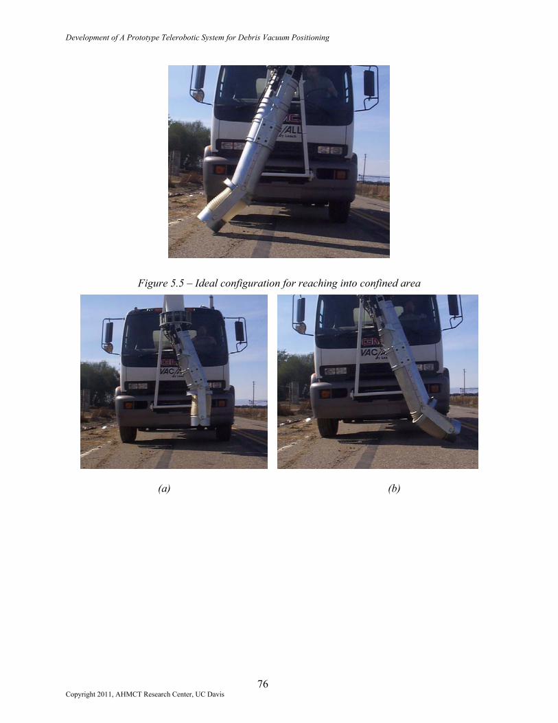
Development of A Prototype Telerobotic System for Debris Vacuum Positioning
Figure 5.5 – Ideal configuration for reaching into confined area
(a) (b)
76 Copyright 2011, AHMCT Research Center, UC Davis

Development of A Prototype Telerobotic System for Debris Vacuum Positioning
(c) (d)
Figure 5.6 – End-effector orientation options
5.4 Workspace and Kinematics
The workspace accessible by the Nozzle end of the end-effector is very similar to that which was intended in the ARDVAC’s design. The connection between the end-effector and the boom at the Upper Joint is free to rotate 360 degrees without the hydraulic hoses attached. In the current ARDVAC assembly, the routing and length of hydraulic hoses that supply the manifold limit rotation about the second axis to roughly +/- 15 degrees. Recall that, with the fixed overhead boom, this degree of freedom is unused on the Engineering Unit.
The sweep arm was intended to rotate +/- 30 degrees from vertical. After assembly it was noted that, when viewed from the front of the vehicle, the sweep arm was 3 to 5 degrees shy of this goal clockwise, and roughly this same amount overturned counterclockwise, while fully retracting or extending (respectively) the short hydraulic cylinder. Closer evaluation revealed a compounding of several small length inaccuracies in the Base weldment and short stroke cylinder. The short cylinder arm at the center front of the Base is roughly 0.64 cm (0.25 in) too high with respect to the bottom of the Base weldment. This offset does not significantly affect the workspace of the end-effector, nor will it noticeably change the device’s ability to retrieve roadway litter items.
The Fly was designed to extend up to 61 cm (24 in) from a fully retracted position, where such a configuration would set the end of the Nozzle 30 cm (12 in) above level ground. In the end-effector assembly, the fully retracted Nozzle rests roughly 28 cm (11 in) above the ground, and the Fly is capable of extending 58 cm (23 in). This slight variation on design dimensions is due to the placement of the U-shaped channel seals attached to the Fly that slide within the Base. As they protrude upward slightly from the top of the Fly, full retraction of the Fly into the Base is halted roughly 2.5 cm (1 in) short of the intended limit where the seals make contact with the top of the long channels. Extension of the Fly is unaffected, and this minor retraction limit will not adversely affect the performance of the ARDVAC.
77 Copyright 2011, AHMCT Research Center, UC Davis

Development of A Prototype Telerobotic System for Debris Vacuum Positioning
A front view of the end-effector’s workspace (without aid of the overhead boom) is shown in Figure 5.7. The workspace is roughly 2.7 m (8.9 ft) across at its widest point, which corresponds to the bottom center of the Nozzle when the Fly is fully extended, and both the sweep arm and Nozzle Bracket are fully rotated in a similar sense. The narrow width is approximately 2.1 m (6.9 ft) across. The horizontal line represents ground level, assuming the Vac/All vehicle is parked on level ground. The bottom center of the Nozzle can function 0 to 69 cm (0 to 27 in) above ground level, and 0 to 31 cm (0 to 12 in) below ground level. Figure 5.8 depicts the view of the same workspace from above the end-effector.
l
Workspace
Copyright
Ground leve
F
Workspace
F
2011, AHMCT Research Ce
2.1
2.7 m
igi
nt
m
ure 5.7 – End-Effector workspace, front view
Workspace
gure 5.8 – End-Effector workspace, top view
78 er, UC Davis
69 cm
31 cm

Development of A Prototype Telerobotic System for Debris Vacuum Positioning
The Nozzle Bracket will rotate +/- 30 degrees with respect to the centerline of the Fly. This is true at any angle of the sweep arm, though recall from Section 5.3.2 that fully rotating the sweep arm and Nozzle Bracket to their fullest opposite extents is not preferable. The four-bar linkage between the Lower Tray, long-stroke cylinders, and Nozzle Bracket works well. As the sweep arm is made to rotate, the Nozzle Bracket fully retains its orientation with respect to the ground. The Nozzle angle can be adjusted, and will still retain its orientation as the sweep arm moves. This will hold true as long as the Nozzle Bracket flare angle is not maximized, generally in the region +/- 20 degrees with respect to the centerline of the Fly.
The operating speed of the end-effector is more than adequate. During its initial use, the end-effector was able to quickly swing back and forth, collecting the majority of light litter materials without any need to slow down. Slower passes were required to collect heavier or bulkier items like metal fragments and cardboard boxes. The current control system does not permit simultaneous extension of the Fly and rotation of the Bracket. This may or may not be a system necessity, a point that will have to be determined with continued use of the ARDVAC system.
5.5 Upper Joint Compression Spring Array
The main intent of this feature is to absorb the energy of any shock or impact loading on the end-effector. However, it also serves to prevent some of the vibration, caused by motion of the sweep arm, from being transmitted into the overhead boom. Motion of the Lower Tray as the springs compress does not degrade the quality of the vacuum seal at the ends of the upper flexible hose. The resilience of the spring joint was tested and proven repeatedly through bluntly striking the end-effector at a variety of angles and heights around the system.
As these loads are applied at points further up from the ground, the springs are less likely to compress. This situation is acceptable in that contact with fixed objects in the roadway will primarily occur near the lowermost features of the sweep arm. The spring array was observed to neatly and quickly reset to its normal position after the removal of each load.
5.6 Summary
The end-effector performs at the level sought after by the goals of the ARDVAC project. There are relatively few individual parts associated with this design, and final assembly of the device, though time consuming in its very first attempt, is straightforward. Manufacturing of the component parts and fabrication of the weldments was time consuming, but the final products fit each other well, and were easily integrated. Once installed onto a system with a moveable boom, the ARDVAC will be ready for use as a high capacity roadway litter-removing tool. Chapter Six will present modification recommendations and some conclusions that have been drawn from this project.
79 Copyright 2011, AHMCT Research Center, UC Davis

Development of A Prototype Telerobotic System for Debris Vacuum Positioning
( This page is intentionally left blank. )
80 Copyright 2011, AHMCT Research Center, UC Davis

Development of A Prototype Telerobotic System for Debris Vacuum Positioning
CHAPTER 6 CONCLUSIONS AND RECOMMENDATIONS
6.1 Project Overview
The AHMCT center has successfully developed and integrated an engineering prototype ARDVAC end-effector onto a truck mounted vacuum system with a stationary 30.5 cm (12 inch) diameter boom. The system can be used by a single operator, and once integrated onto a commercial vehicle with an articulating boom, it will be useful in median divider areas and shoulders, around guardrails, and on embankments nearest to roadways. The ARDVAC has been tested and shown to successfully remove light debris (paper, cups, aluminum cans, fast food packaging) and heavier trash (glass bottles). The end-effector will function without requiring its operator to leave the vehicle’s cab, and no on-site set-up is necessary. The ARDVAC is intended to fulfill Caltrans’ original project goal of developing a vehicle capable of efficiently removing roadway litter and light trash.
The ARDVAC’s vacuum hose positioning system has been developed from perceived vehicle needs, to a variety of concepts, through concept selection, and into detailed design. Assembly and limited testing of the automated vacuum hose has proven the device’s effectiveness. This chapter suggests some minor modifications to the design of the end-effector and includes final conclusions and recommendations.
6.2 Suggested Modifications
6.2.1 The Upper Tray
The felt used to create the vacuum seal at the Upper Tray was purchased with an adhesive backing. This adhesive holds the felt to the Upper Tray to form the vacuum seal between the Upper Tray and boom end lip, but may degrade over the course of many hours of machine operation. The felt material itself may not respond well to moisture exposure, should any liquids be drawn into the vacuum system, perhaps in a beverage container or from damp vegetation picked up after a rainstorm. For long-term use of the ARDVAC, the felt may need to be replaced by a pliable rubber capable of withstanding abrasion from small litter items that strike it on their way into the overhead boom. It must not wear as it slides against the boom lip, and it must not rip or tear at its points of attachment to the Upper Tray.
6.2.2 The Lower Tray
Use of the long-stroke cylinders particular to this project required the hydraulic pressure to the end-effector manifold be maintained at or below 3450 kPa (500 psi). Replacement cylinders built specifically for hydraulic use and designed for normal operating pressures of 17200 kPa (2500 psi) have been purchased and will be installed on the end-effector when it is integrated onto the second Leach Vac/All machine. These newer cylinders, however, have larger bore caps than the converted pneumatic cylinders. Attaching them to the existing cylinder mounts of the
81 Copyright 2011, AHMCT Research Center, UC Davis

Development of A Prototype Telerobotic System for Debris Vacuum Positioning
Lower Tray would cause interference between the cylinders and Base. To remedy this, the long-stroke cylinder mounts will need to be moved away from the end-effector’s vertical centerline.
The current Lower Tray design places the mounts very close to the outer edge of the tray, as shown in Figure 6.1. This design permits adequate space to weld the mounts to the round plate of the Tray, however the mounts will need to be moved at least 1.3 cm (0.5 in) away from the center of the plate. This may require the fabrication of a replacement Lower Tray weldment with a larger outer diameter or tabs to support the cylinder mounts.
Cylinder mounts close to outer diameter of Lower Tray
Figure 6.1 – Proximity of cylinder mount flanges to edge of Lower Tray
6.2.3 The Nozzle Bracket
The geometry of the cylinder pivot flange that fastens to the top rear of the Nozzle Bracket can bind the clevis attachments of the long-stroke cylinders and place a bending moment on the cylinder rods. This occurs only when the sweep arm and Nozzle Bracket are rotated to their fullest extents in opposite senses, as described in Chapter 5. The pivot flange was originally designed to permit the rod clevises of the long-stroke cylinders to freely rotate +/- 30 degrees about the vertical of the flange as shown in Figure 6.2. Binding of the rod clevises occurs where the inner surface of a clevis makes contact with this clearance corner, at angles greater than 30 degrees.
Clevis clearancecorners
Copyright 2011
60°
Figure 6.2 – Original design of cylinder pivot flange
82 , AHMCT Research Center, UC Davis

Development of A Prototype Telerobotic System for Debris Vacuum Positioning
To prevent this, the clearance corners should be made deeper, and material should be added to the lower portion of the pivot flange to maintain the strength of the object, as suggested by the sketch in Figure 6.3. Note that the inner surface of a rod clevis could still interfere with this clearance corner. However, rotation of the Nozzle Bracket with respect to the Fly will be halted by the Nozzle Bracket’s contact with the Fly or Base before the clevises can reach rotational their travel limits on the pivot flange.
Figure 6.3 – A potential redesign of the cylinder pivot flange
6.3 Conclusion
The ARDVAC concept has performed well and, when combined with the vacuum power of a commercial vacuum truck, it is expected that this system will be an effective tool. This device could be marketed as an add-on option for an entire array of applications not limited to roadway litter removal. It has potential uses in municipalities, state Departments of Transportation, landfill operations, and any of a variety of large-scale vacuum cleaning applications.
Additional real world testing is required to optimize the design. An additional linkage or hydraulic actuator is required to control the vertical axis rotation along the second axis (from Chapter 3’s designation) of the end-effector. A more developed control system should be considered to include position sensors and automated operation options such as a constant sweep function. An improved control system should allow for full use of the multi-function joystick and it should integrate the commercial boom controls into the joystick’s functions. It is recommended that these modifications should be implemented prior to field testing.
83 Copyright 2011, AHMCT Research Center, UC Davis

Development of A Prototype Telerobotic System for Debris Vacuum Positioning
( This page is intentionally left blank. )
84 Copyright 2011, AHMCT Research Center, UC Davis