development of a prototype plastic space …tech library kafb. nm ooboljoli nasa cr- 892 development...
TRANSCRIPT

NASA CONTRACTOR
REPORT
DEVELOPMENT OF A PROTOTYPE PLASTIC SPACE ERECTABLE SATELLITE
by Vincent F. LYAgostino und Preston Kezlscb
Prepared by
RAI RESEARCH CORPORATION
Long Island City, N.Y.
for Goddard Space FZigbt Center
NATIONAL AERONAUTICS AND SPACE ADMINISTRATION . WASHINGTON, D. C. l SEPTEMBER 1967
https://ntrs.nasa.gov/search.jsp?R=19670028244 2020-04-27T08:24:37+00:00Z

TECH LIBRARY KAFB. NM
OObOlJOli NASA CR- 892
DEVELOPMENT OF A PROTOTYPE PLASTIC SPACE
ERECTABLE SATELLITE
By Vincent F. D’Agostino and Preston Keusch
Distribution of this report is provided in the interest of information exchange. Responsibility for the contents resides in the author or organization that prepared it.
Prepared under Contract No. NAS 5-3923 by RAI RESEARCH CORPORATION
Long Island City, N.Y.
for Goddard Space Flight Center
NATIONAL AERONAUTICS AND SPACE ADMINISTRATION
For sale by the Clearinghouse for Federal Scientific and Technical Information
Springfield, Virginia 22151 - CFSTI price $3.00


1.0 2; 1:2.1 1.2.1.1 1.2.1.2 1.2.2 1.2.3
2.0 2.1 2;1.1 2.1.2 2.1.3 2.1.4 2e1.5
2.1.6 2.1.7
Xl
2.2.2
2.2.3
2.2.4
Xl 2.3.2 2.3.3
3.0
;:2 3.2.1 3.2.1.1 3.2.1.2 3.2.2
3.2.2.1 3.2.2.?
;:Z 3: . .
TABLE OF CONTENTS
Page
ABSTRACT . . . . . . . . . . . . . . . . . . . . . . . . . . . . . . . . Xii
INTRODUCTION ............................ General ................................. History ................................. Memory Effect Background ................ Degree of Restoration ................... z Restoration Force ....................... Memory Phenomenon in Polyethylene ....... ;3 Background on Materials Selection ....... 12
MATERIAL PROPERTIES DEVELOPMENT PROGRAM. Z!; Extraction Study .... ............ ........ Variation of Strength with Dose ......... Solvent Tests ........................... :; Extraction .............................. Gel Fractions ........................... E; Strength Dose Variations of Extracted Material ................................ 27 Densities of Extracted Polyethylene Film 29 Results of Extraction Program ........... 31 Development of Laminate ................. 31 Flexural Rigidities of Metallized Polyethylene Film ....................... Flexural Rigidities of PE 11 (Plated)
32
Type Films .............................. Flexural Rigidities of PE 12 (Plated)
33
Films ................................... 33 Flexural Rigidities of Plated PE 12 Film over the Complete Range of Film Thicknesses ............................. Perforations ............................ z; Flexural Rigidity of Perforated Film .... 40 Electrical Resistance of Perforated Film 41 Conclusions on Perforation Tests ........ 45
BUCKLING PRESSURE - THICKNESS STUDY ..... Theoretical Equation .................... z:: Spherical Cap Models .................... 49 No Material Correction Factor ........... 49 Uniformly Loaded Cap Section ............ 49 Point Loaded Cap Section ................ 51 Calculation with Material Correction Factor ................................... Uniformly Loaded Cap Section ............ z Point Loaded Cap Section ............. ... Comparison of Derived Film Thicknesses . . ;89 Perforation Optlmlzatlon - Satellite Weight .................................. Satellite Weight vs. Void Fraction ...... zz Perforation Optimization ................. 63
iii

4.1.2.3 4.1.2.3.1 ;.;.$.;.g
4:1:2:3:4
4.1.7,l
m2 . . 4.2 4.2.1 4.2.1.1 4.2.1.2 4.2.1.2.1 ;.;.;.;.g
;:;:;:2:4
41212.1 4.2.2.1.1 ;.;.;.;.2
4:2:2:3
4.3.1.2 4.3.1.2.1 ;.;.;.;.;i;
4:3:1:2:1:3
TABLE OF CONTENTS (Continued)
Page
TEST MODELS AND PRODUCTION .............. 66 Operating Variables and Procedures in Construction of Large Deliverable Items. 67 Base Material Manufacture ............... 67 Film Extrusion .......................... 67 Mesh Production .........................
Irradiation ............................. g;
Dosage .................................. Irradiation Source ...................... Irradiation Atmosphere Tests ............
gi
Initial Tests: Air, Nitrogen ............ Tests: Oxygen, Nitrogen, Air ............ Effect of Dose ..........................
f!
Scatter in the Irradiation Atmosphere Tests ................................... 87 Heat Treatment .......................... Perforations ............................ Metallization ...........................
$j
Electroless Copper Plating .............. 90 Recommended Plating Cycle ............... Plating Cycle for Mesh .................. ;: Plating Cycle Film ...................... 93 Aluminum Deposition Cutting ......................................................
.;;
Ultrasonic Bonding ...................... 97 Bonding of Mesh ......................... 98 Bonding of Film Packaging ....................................................
..lz;
.. Test Model Fabrication Proced,ures.......lO 0 Mesh .................................... 102 Cap Section Design ...................... 102 Cap Section Fabrication............;....10 4 Irradiation - Mesh ....... ..*............lO 4 Heat Treatment - Mesh...................10 4 Electroless Plating - Mesh..............10 5 Ultrasonic Bonding - Mesh...............10 5 Film .................................... 105 Irradiation - Film ...................... 105 Irradiation of Flat Film................;; 2 Irradiation of Cylinders ................ Heat Treatment -Film...................10 6 Electroless Plating - of Film...........10 8 Ultrasonic Bonding - of Film............10 8 Scale-Up ................................ 110 Stages Requiring Scale Up...............11 0 Heat Treatment .......................... 110 Electroless Plating.....................11 1 Plating Baths ........................... 111 Cleaning Bath ........................... 112 Neutralizing Bath ......... ..w ........... 113 Conditioning Bath ....................... Sensitizer and Activator Stages ......... I': 2 Electroless Plating Bath................11 4
iV

4.3.1.2.1.6 ~.~.;.;.1.7
. . .
5.0 5.1 5.1.1
;*z 5x4 5.2
6.0
E?; 612.1 2.g.2 . . 2 is:5
6.2.6
7.0 7.1
8.0
9.0
APPENDIX I
APPENDIX II
APPENDIX III
APPENDIX IV
APPENDIX V
APPENDIX VI
APPENDIX VII RESISTANCE DATA ON TEST MODELS l . . . VII-~ -VII-~
APPENDIX VIII
TABLE OF CONTENTS (Continued)
Page
Antioxidant Step ......................... 116 Rinsing Steps ............................ 116 Packaging ................................ 116
MEMORY EFFECT ............................ Experimental Tests ....................... "I'l: Memory Effect and Characterization of Memory Forces . Tensile Tests ............ 118 Fold Resistance Tests .................... 122 Cylinder Deployment Tests................12 2 Conclusions on Memory Test...............12 7 Deployment ............................... 127
TESTING PROGRAM .......................... 129 Initial Qualifications Testing Program.,.130 Final Qualifications Testing Program.....13 0 Tensile Tests ............................ 139 Flexural Rigidity Tests .................. 139 Cyclic Flexure Endurance Test............13 9 Fold Resistance Tests ........... ..*...*.*15 4 Final Qualifications Test - Bonded Material ................................. 159 Blocking Tests .......................... . 159
CONCLUSION AND RECOMMENDATIONS ........... 166 Material Properties Development Program and Buckling Pressure Evaluation.........16 6 Test Models and Production...............16 7' Memory Effect and Deployment.............16 9 Thermal Control Coating .................. 170
LIST OF SYMBOLS .......................... 172
REFERENCES ............................... 175
TENSILE TESTS ...................... I-l-- I-3
CRYSTALLINE MELTING POINT (T,) OF PE 12 .............................. II-1 - 11-5
DENSITY GRADIENT COLUMN ........... III-l -111-3
FLEXURAL RIGIDITY TEST ............ IV-1 - IV-2
ANALYTICAL PROCEDURES FOR PLATING BATHS IN ENTHONE PLATING CYCLE l . . . V-l - v-g
CAP SECTION DESIGN CALCULATIONS... VI-~ - v1-4
THERMAL CONTROL PROPERTIES OF METALLIZED FILM . . . . . . . . . . . . . . . . . . . VIII-1
v

Table
1
5
6
7
8
9
10
11
12
13
14
15
16
17
18
19
LIST OF TABLES
Page
Dimensional Stability of Polyethylene Mono- filament with Respect to Heat Treatment . . . . . . . . . . 13
Dimensional Stability of Rexwell Mesh . . . . . . . . . . . . 15
Properties of Processed Rexwell Mesh . . . . . . . . . . . . . 16,17
Physical Properties of,Sea Space Intermediate Density, 1 Mil, Biaxially Oriented Polyethylene Film (PE 12) .o......*............................ 22
Effect of Radiation Dose on the Strength of 1 Ml1 Standard Density Sea Space Polyethylene Film..... 26
Extraction Efficiency of Various Solvents on Polyethylene . . . . . . . . . ..*......................... 26
Effect of Complete Extraction on Strength of 1 Mil Standard Density Sea Space Polyethylene Film Given Various Doses of Radiation . . . . . . . . . . . . 29
Densities of Extracted-Crosslinked PE 11 . . . . . . . . . 31
Flexural Rigidity as a Function of Film Thickness with Electroless Plating Time as a Parameter..... 34
Flexural Rigidity of Unplated PE 11 vs. Thickness 37
Perforator Dimensions . . . . . . . . . . . . ..*.'..*o........ 40
Effect of Perforation on 0.30 Mil Plated Standard Density Polyethylene Film l . . . . . l . . . . . . . . . 42
Resistance of Plated (15 x 10B6 in, Cu) Perforated, Standard Density Polyethylene Film... 44
Resistance of Perforated-Plated (15 x 10-6 in. Cu) Standard Density Polyethylene Film . . . . . . . . . . . . . . . 44
Solutions to Equation (17)........*...........*.. 56
Polyethylene Thicknesses of Composite Film - Solutions to Equation (19) (15 x 10B6 inches of Copper Plate on both sides)...................,, 59
Derived Thickness of Polyethylene Film . . . . . . . . . . . 61
Satellite Weights - Perforated................... 62
Irradiation Heat Treatment Atmosphere Experimental Scheme (Air, Nitrogen) Irradiation of 1 Ml1 Sea Space Polyethylene Film to 15 Mrads . . . . . . . . . . . . . . 69
Vi

LIST OF TABLES (Continued)
Page Table
20
21
22
23
24
25
26
27
28
29
30
31
32
33
34
35
Irradiation Heat Treatment Atmosphere Experimental Scheme (Oxygen, Nitrogen, Air) Irradiation of 1 Ml1 Sea Space Polyethylene Film to 15 Mrads . . . . . . . . . . . . . . . . . . . . . . . . . . . . . . . . . . 70
Properties of Aluminized Polyethylene Film, Aluminized by National Metallizing Div. of Standard Packaging Co,, Trenton, N.J. .,....,.... 95
Properties of Conductive Lacquer . . ..*..*......... 109
Summary of Immersed Lengths of Travel in all Plating Baths to obtain a Copper Thickness of 15 x 10-6 in. on Polyethylene film...............112
Characterization of Memory Forces - Modulus of Elasticity, E, PE 12 Irradiated to 15 and 70 Mrads . . . . . . . . . . . . . . . . . . . . . ..*.................... 120
Summary of Cylinder Restoration Tests (Base Material PE 12 Irradiated on a Cylinder).........123
Testing Program Scheme . . . . . . . . . . . . . ..*........... 129
Properties of Processed Sea Space Film . . . . . . . . . . . 131,132
Final Qualifications Test: Tensiles..............l40
Final Qualifications Test: Flexural Rigidity.....l5l
Final Qualifications Test: Cyclic Flexure Endurance . . . . . . . . . . . . . . . . . . . . . . . . . . . . . . . ...*..... 152
Final Qualifications Test: Fold Resistance..,....155
Final Qualifications Test: Tensiles (Bonded).....160
Final Qualifications Test: Flexural Rigidity (Bonded) . . . . . . . . ..-........a...................... 161
Final Qualifications Test: Cyclic Flexure Endurance (Bonded) . . . . . . . ..*..................... 162
Blocking Tests . . . . . . . . . . . . . . . . . . . . . . . . . . . . . . . . . . . 165
Vii
IL-.

I I II I
Figure
1
2
3
4
9
10
11
12
LIST OF ILLUSTRATIONS
Page
PHOTOGRAPHS OF REXWELL POLYETHYLENE MESH . . . . . . . . . 19
PHOTOMICROGRAPHS OF REXWELL MX-44 PLATED MESH (200x) . . . . . ..*................................... 20
GEL FRACTIONS OF IRRADIATED POLYETHYLENE FOR VARYING RADIATION DOSES . . . . . . . . . . . . . . . . . . . . . . . . . . 28
EFFECT OF COMPLETE EXTRACTION ON STRENGTH OF 1 MIL STANDARD DENSITY SEA SPACE POLYETHYLENE FILM GIVEN VARIOUS DOSES OF RADIATION............ 30
EXPERIMENTAL FLEXURAL RIGIDITIES ................. 36
PERFORATOR-DIE PATTERN, DETAIL 1 ................. 38
PERFORATOR-DIE PATTERN, DETAIL 2 ................. 39
FLEXURAL RIGIDITY'OF PERFORATED 0.30 MIL STANDARD DENSITY POLYETHYLENE FILM VS. PERCENT OPEN AREA (Plated to 15 x 10-6 inches on both Sides) a-*?....................................... 43
RESISTANCE (n/SQ.) OF PERFORATED 0.30 MIL STANDARD DENSITY POLYETHYLENE FILM VS. PERCENT OPEN AREA (Plated to 15 x 10-6 in. Cu on both Sides) . . . . . . . . . . . . . . . . . . . . . . . . . . . . . . . . . . . . . . . . . . . 46
Per THE FUNCTION U(p) = - t2
u(p) = 2Ek4 PO,(P) R2
FOR POLYETHYLENE CAP SECTION . . . . . . . . . . . . . . . . . . . . 50
TRANSFORMATION FROM DISTRIBUTED LOAD TO POINT LOAD . . . . . . . . . . . . . . . . . . . . . . . . . . . . . . . . . . . . . . . . . . . . . 52
THE FUNCTION F(p) (POLYETHYLENE) . . . . . . . . . . . . . . . . . 54
F(p) = 2 E 1 TT R2k2
( 1O;2kp +
Viii

LIST OF ILLUSTRATIONS (Continued)
Figure Page
13 THE FUNCTION H(t) =h&........................ 57
14 THE FUNCTION F'(p)
F'(p) = 241 TT R2kSP cr
. . . . . . . . . . . . . . . 60
15 RATIO OF FLEXURAL RIGIDITIES Q(Fv) AFTER PERmRATION TO BEFORE PERFORATION FOR 0.30 MIL POLYETHYLENE COATED WITH 15 x lO-6 INCHES OF COPPER ON BOTH SIDES AFTER PERFORATION . . . . . . . . . . . 65
16 THE FUNCTION A(F,) = 1 -Fv WHERE Q(F,) IS GIVEN &(
IN FIGURE 15 ..,.................................. 65
17 STRENGTH-TIME CURVES FOR IRRADIATED (15 MRADS) 1 MIL SEA SPACE STANDARD DENSITY POLYETHYLENE FILM . . . . . . . . . . . . . . . . . . . . . . . . . . . . . . . . . . . . . . . . . . . . . ~72
18 Ditto . . . . . . . . . . . . . . . . . . . . . . . . . . . . . . . . . . . . . . . . . . . . 73
19 Ditto . . . . . . . . . . . . . . . . . . . . . . . . . . . . . . . . . . . . . . . . . . . . 74
20 Ditto . . . . . . . . . . . . . . . . . . . . . . . . . . . ..*.............. 75
21&22 Ditto . . . . . . . . . . . . . . . . . . . . . . . . . . . . . . . . . . . . . . . . . . . . 76
23&24 Ditto . . . . . . . . . . . . . . . . . . . . . . . . . . . . . . . . . . . . . . . . . . . . 77
25 Ditto . . . . . . . . . . . . . . . . . . . . . . . . . . . . . . . . . . . . . . . . . . . . 78
26 Ditto ............................................ 79
27 Ditto ............................................ 80
Ditto . . . . . . . . . . . . . . . . . . . . . . . . . . . . . . . . . . . . . . . . . . . . 81
29 Ditto . . . . . . . . . . . . . . . . . . . . . . . . . . . . . . . . . . . . . . . . . . . . 82
30 STRENGTH-TIME CURVES FOR IRRADIATED (30 MRADS) 1 MIL SEA SPACE STANDARD DENSITY POLYETHYLENE FILM . . . . . . . . . . . . . . . . . . . . . . . . . . . . . . . . . . . . . . . . . . . . . 83
31
32
33
Ditto ............................................ 84
Ditto ............................................ 85
Ditto ............................................ 86 IX

Figure
34
35
36
37
38
39
40
41
42
43
44
45
46
47
48
49
50
51
52
53
54
55
LIST OF ILLUSTRATIONS (Continued)
Page
PERCENTAGE DEPTH DOSE IN WATER FOR HIGH ENERGY ELECTRONS . . . . . . . . . ..*....................... 87
ALUMINIZED IRRADIATED FILM . . . . . . . . . . . . . . . . . . . . . . . . . 96
SCHEMATIC DIAGRAM OF ULTRASONIC BONDER . , . . . . . . . . . . . 98
ULTRASONIC WELDER .................................. 101
LOCATION OF CAP SECTION WITHIN GORE SECTION OF CONSTRUCTED SPHERE ................................. 103
CAP SECTION CROSS-SECTION .......................... 103
SELECTED AREAS OF REMOVED COPPER ................... 107
SCHEMATIC DIAGRAM OF CONTINUOUS FILM IRRADIATION...10 'j'
SCHEMATIC OF SENSITIZER OR ACTIVATOR SYSTEMS.......11 3
CONDITIONER BATH ................................... 114
ELECTROLESS PLATING BATH ........................... 115
SCHEMATIC DIAGRAM OF PLATING BATH SYSTEM ........... 116
TYPICAL STRESS CURVE OF ELASTOMERIC POLYETHYLENE...12 1
SCHEMATIC 0~ CYLINDER DEPLOYMENT msm.............i2 2
PHOTOGRAPHIC RESULTS OF CYLINDRICAL MEMORY TESTS ON UNPLATED MATERIAL . . . . . . . . . . . . . . . . . . . . . . . . . . . . . . . 124
PHOTOGRAPHIC RESULTS OF CYLINDRICAL MEMORY TESTS ON UNPLATED MATERIAL . . . . . . . . . . . . . . . . . . . . . . . . . . . . . . . 125
PHOTOGRAPHIC RESULTS OF CYLINDRICAL MEMORY TEST ON PLATED MATERIAL WITH COPPER REMOVED FROM ~m~s..126
SURFACE RESISTANCE VS. STRAIN FOR COMPLETED MATERIAL, NON-PERFORATED (in Oo and 450 Directions) . . . . . . . . . . . . . . . . . . . . . . . . . i33
SURFACE RESISTANCE VS. STRAIN FOR COMPLETED MATERIAL, NON-PERFORATED (in go0 Direction)........134
SURFACE RESISTANCE VS. STRAIN FOR COMPLETED MATERIAL (in Oo Direction) . . . . . . . . . . . . . . . . . . . . . . . . . 135
SURFACE RESISTANCE VS. STRAIN FOR COMPLETED MATERIAL (in 4,5O Direction) . . . . . . . . . . . . . . . . . . . . . ...136
SURFACE RESISTANCE VS. STRAIN FOR COMPLETED MATERIAL (in go0 Direction) . . . . . . . . . . . . . . . . . . . . . . . . 137
X

LIST OF ILLUSTRATIONS (Continued)
Page
PHOTOMICROGRAPHS OF PLATED MATERIAL PERFORATED AND UNPERmRATED (250X) . . . . . . ..*.................. 138
SJRFACE RESISTANCE VS. STRAIN FOR COMPLETED MATERIAL (in O", 450 and 900 Directions) . . . . . . . . . . 141
SURFACE RESISTANCE VS. STRAIN FOR COMPLETED MATERIAL (In Oo and 450 Directions)...............142
SURFACE RESISTANCE VS. STRAIN F0R COMPLETED MATERIAL (In 900 Direction) . . . ..*................. 143
SURFACE RESISTANCE VS. STRAIN FOR COMPLETED MATERIAL (00 Direction) . . . . . . . . . . . . . . . . . . . . . . . . . . . 144
SURFACE RESISTANCE VS. STRAIN FOR COMPLETED MATERIAL (In 450 and go0 Dlrections)..............lbj
SURFACE RESISTANCE VS. STRAIN FOR COMPLETED MATERIAL (in Oo Direction) . . . . . . . . . . . . . . . . . . . . . . . . 146
SURFACE RESISTANCE VS. STRAIN FOR COMPLETED MATERIAL (in 450 and 900 Di.rections).............elb7
SURFACE RESISTANCE VS. STRAIN l33R COMPLETED MATERIAL.(ln 00, 450 and 900 Directions) . . . . . . . . . . 148
SURFACE RESISTANCE VS. STRAIN FOR COMPLETED MATERIAL (in 00, 450 and 900 Directions)..........149
SURFACE RESISTANCE VS. STRAIN FOR COMPLETED MATERIAL (in 00, 450 and 900 Directions) . . . . . . . . . . 150
CYCLIC FLEXURE ENDURANCE SCHEMATIC DIAGRAM . . . . . . . . 153
CYCLIC FLEXURAL ENDURANCE TEST (250x) . . . . . . . . . . . . . 156
FOLD RESISTANCE TEST ON PERFORATED, PLATED MATERIAL (250x) . . . . . . . . . . . . . . . . . . . . . . . . . . . . . . . . . . . 156
FOLD RESISTANCE TEST ON PERFORATED, PIATED MATERIAL (250x) . . . . . . . . . . . . . . . . . . . . . . . . . . . . . . . . . . . 157
FOLD RESISTANCE TEST ON PERFORATED, PLATED MATERIAL(250x) . . . . . . . . . . . . . . . . . . . . . . ..a........... 157
FOLD RESISTANCE TEST ON PERFotiTED PLATED MATERIAL . . . . . . . . . . . . . . . . . . . . . . . . . . . . . . . . . . . . . . . . . . 158
TENSILE TEST ON BONDED PERFORATED, PLATED MATERIAL (250x) . . . . . . . . . . . . . . . . . . . . . . . . . . . . . . . . . . . 163
CYCLIC FLEXURAL ENDURANCE ON BONDED, PERFORATED PLATED MATERIAL (250x) . . . . . . . . . . . . . . . . . . . . . . . . . . . . 163
Xi
FigUI-e
56
57
58
59
60
61
62
63
64
65
66
67
68
69
70
71
72
73
74

ABSTRACT
This report describes the work done.,and conclusions
resulting in the development of procedures and data for
construction of a prototype space erectable plastic passive
communications satellite of spherical design with a diameter
of 425 ft. using the plastic memory effect. Research under
this contract has resulted in the development of a crosslinked
polyethylene metal laminate weighing 1.58 x 10e3 lbs./ft.2
(resulting in a satellite weight of 896.6 lbs.) and capable
of withstanding solar pressures when fabricated into a sphere
with a 425 ft. diameter. Experimental data and theoretical
calculation indicate that a 0.30 mil perforated polyethylene film
electrolessly plated with 15 x 10D6. inches of copper on both
sides would be satisfactory to withstand buckling pressures
within the weight conditions. specified.
Prototype items were constructed and delivered
following a detailed testing program on the various materials
used In construction. Additionally, the procedures necessary for
the scale-up and production of a 425.foat diameter spherical
passive communications satellite were investigated in this
study. Recommendations for construction are detailed in this
report. The results of the testing program and the building
of the deliverable Items (cap section, cylinders and flat
sections) show that the crosslinked polyethylene copper
laminate film developed under this contract is satisfactory
for building large, self-erectable satellites. Although It
was not possible to conclusively demonstrate the plastic memory
effect, in a l-g field, on thin polyethylene (sub-mil) film
models, the memory effect has been demonstrated on a 15 mil
xii

polyethylene mesh. Other tests (not using models) and based
on firm theoretical grounds substantiate the existence of the
memory effect in thin film polyethylene.
It is recommended that an experimental O-g deployment
study be undertaken to conclusively demonstrate the plastic
memory effect on thin polyethylene film in the absence of a
gravitational field. Another area requiring investigation to
complete the goals of the overall program is a thermal control
study, since it was not included in the scope of this program.
xiii

1.0 IN!TRODUCTION
1.1 General
The scope of this contract and the sequence of the
investigations undertaken during this program are presented
in this section. The objective of this program was to develop
a polyethylene film with an area weight of less than
1.72 x 1O-3 lbs./ft.:! which was capable of withstanding five
times solar buckling pressure when fabricated with a sphere of
425 ft. diameter. This program is a change in emphasis from
the Initial program NASr-78 which was primarily concerned with
an investigation of the mechanism of the memory phenomenon and
the memory forces. In addition to the development of a light-
weight film the material developed here was also required to act
as a reflector of RF frequency (90-95s reflectance at 8-g GHz
frequencies). The material must, therefore, receive a metal
coating and exhibit a resistance of less than 2 ohms/square.
Included in the scope of this investigation was a
continuing clarification of the mechanism of the memory
phenomenon. All these objectives have been accomplished.
The materials investigated under this contract Included
polyethylene meshes and films of various densities and thicknesses.
The film materials were laminated by electroless plating with
various thicknesses of copper and buckling pressure calculations
were undertaken to determine the proper laminate thickness
necessary to withstand five times solar pressure. Results
showed that a laminate of 0.30 mil polyethylene and 30 x 10 . -' in
(15 x 10 -6 in. on both sides of the film) of copper met the weight
and strength qualifications. Studies were then performed on
film perforation and film extraction as a means of decreasing
-l-

the film weight. Studies eliminated the possibility of lowering
the weight of film by extraction. It was found, however, that
the film could be perforated to 40% open area while retaining
its required physical resistance to solar buckling pressure.
Upon completion of the above-mentioned studies a
production study program was undertaken to produce a perforated
polyethylene film laminated with copper. The steps in the
production program were as follows:
1. Film extrusion (blown film).
2. Irradiation of the extruded film,
3. Heat treatment (annealing) of the irradiated film.
4. Perforation of the annealed film.
5. Electroless plating.
A detailed experimental testing program was subsequently
undertaken on the laminated material. Results showed that the
production -material was suitable for the construction of a
large passive communications satellite.
As part of the overall program a number of deliverable
items were constructed to be used for radio-frequency tests by
NASA. The items constructed and delivered were as follows:
1. A 24 ft. chord diameter spherical cap section of 212 ft. radius of curvature (mesh).
2. Seven cylinders 7..5 in. diameter x 1 ft. length (mesh and film).
3. Six flat sections (41 x 61) (mesh and film).
With the completion of the deliverable items and the
testing program, recommendations and procedures for the scale-up,
production and packaging of full size passive communications
satellites were determined. These included a determination of
-2-

the five steps listed above plus:
6. Cutting of gore sections.
7. Ultrasonic bonding.
8. Packaging.
The final phase of this program was a study of the
memory forces In thin film as a means of clarifying the
mechanism of the memory phenomenon. Difficulty was encountered
in demonstrating the memory effect on thin gauge polyethylene
models since gravitational and air circulation forces both
exceeded the memory force and acted to resist its effect.
After evaluation of numerous methods it was shown that the
memory effect could be observed for heavy mesh material. The
transition of the observation of the memory phenomenon to
thin film was finally shown by use of tensile test data above
the crystalline melting point (T,) of the polyethylene. This
procedure which conclusively proves the existence of the memory
effect on thin gauge film is based on a firm theoretical
background developed for rubber elasticity. The results
obtained prove the existence of memory in a "l-g" environment.
Extrapolation to a O-g environment cannot be rigorously proven
but since the removal of gravity forces should not change the
elastomeric forces it is intuitively concluded that this
‘system will operate in a O-g environment.
1.2 History
1.2.1 Memory Effect Background
The memory effect induced in polyethylene by
irradiation of plastic with either beta or gamma radiation was
first noted by Charlesby' in his book, "Atomic Radiation
and Polymers" wherein he describes the memory phenomenon as
-3-

'an interesting and often amusing property of lightly lrradi-
ated polyethylene". He notes further that the memory phenomenon
'relies on the fact that on irradiation a crosslinked network
Is formed with a definite equilibrium state. When other
constraints such as crystallinity or external stresses are
removed, the polymer will return to the same molecular arrange-
ment it had during radiation". The memory effect will be
discussed more fully in a subsequent section of this report.
The application of this plastic memory effect to
the development of a space structure was first proposed by
R A I In 1961. This resulted in a preliminary study of the
phenomenon under contract to the National Aeronautics and
Space Administration. The scope of work under this contract,
although empirical in nature, was directed toward an
investigation of the mechanism of the memory phenomenon to
permit adaptation of the process to development of erectable
space structures. To this end the following was investigated:
1. The magnitude of the restoration-forces exerted
by Irradiated sheet material (40 mils) during the process of
restoration to the undeformed state.
2. The degree of completeness with which memory
occurs as a function of the Tm (I.e., the crystalline melt
temperature of the polymer).
3. The conditions required to change the minimum
restoration temperature at which complete restoration could
be effected were also studied by an evaluation of polyethylene
and copolymers of polyethylene.
The emphasis of this effort was, therefore, a study
of all the factors noted above on sheet and to a limited extent
-4,

on mesh material. A summary of results of this study is given
below. By degree of restoration referred to below is meant
the extent of recovery of a deformed article to its original
configuration. The "NT" deformation term refers to deformation
of a sample of crosslinked polyethylene at a temperature below
the melt temperature of the crystalline melting point. At this
stage the polyethylene is Eon-Transparent. The T deformation
refers to deforming a polyethylene sample after it has been
heated above its crystalline melting point (T,). At this tempera-
ture the plastic is Transparent.
The results from contract NASr-78 on degree of
restoration and the restoration were as follows:
1.2.1.1 Degree of Restoration
a. The deformation conditions were found to have no
effect on the degree of restoration. Complete restoration
occurs under a variety of deformation conditic;ns if the
restoration temperature is above the crystalline melting point
of the polymer.
b. The restoration conditions are of major importance
in controlling the degree of restoration of deformed polyethylene.
For restoration to be complete, the polyethylene must be heated
to transparency (I.e., above its normal T,). For high density
polyethylene, this temperature is ca. 130-135OC.; for low
density, the required temperature is ca. 105oC. Polyethylene
copolymers containing 15% or more ethyl acrylate or vinyl
acetate were found to require lower minimum restoration tempera-
tures than the homopolymers since their T, values were lower.
Thus, the various acrylate and acetate copolymers studied
restored at temperatures of 65-gO°C.
-5-

c. Unlrradlated and irradiated polyethylene behave
very similarly at deformation temperatures below Tm. Above
T mr unlrradiated polyethylene melts and flows and, thus,
memory cannot be observed.
d. Radiation dose does not control the degree of
restoration above the minimal dose of ca. 5-10 Mrads for a
polyethylene of & of at least 70,000.
e. Polyethylene density affects the degree of
restoration only insofar as it affects the normal crystalline
melting point of the polymer (see paragraph c above). Low
.density grades restore the completion at lower temperatures
than high density grades.
f. Initial molecular weight, above a certain minimum,
is not a factor In controlling the degree of restoration;
however, this is closely related to the radiation dose
(see paragraph d above). A 10 Mrad dose to a polyethylene
of Fi, of ca. 70,000 gives complete restoration.
g. Storage of NT deformed specimens at -780~. will
prevent creep which is common at ambient temperatures and
retarded at -15'C.
h. Moulding and extrusion-induced stresses and strains
in polyethylene complicate the memory effect studied on this
project. Such complications can, however, be minimized by
annealing techniques.
I. Vexar polyethylene mesh behaves exactly similar
to polyethylene sheet as regards the memory effect.
j. The acrylate and acetate copolymers of polyethylene
exhibit the memory effect as does polyethylene.
-6-

1.2.1.2 Restoration Force
a. Deformation conditions greatly influence the
restoration force. NT deformed polyethylene has much greater
restoration forces than T deformed polyethylene.
b. The restoring force increases with radiation dose
for both T and NT deformed polyethylene.
C, The restoring force for NT deformed polyethylene
Increases with increasing polymer density and Tm.
d. The restoring force increases with increasing
molecular weight (as measured under T deformation conditions).
e. The restoring force is proportional to the square
of the polyethylene thickness for NT deformed polyethylene over
the 20-60 ml1 thickness range.
f. Quenching and moulding conditions do not appear
to affect the restoring force.
g. The presence of ZnO or Casio3 fillers in the
polyethylene prior to irradiation lowers the restoring force.
The results of the original effort (contract NASr-78)
describes the memory force in plastics at various temperatures
in terms of both a plastic (NT) and elastic (T) memory. It is
noted from these results that the complete restoration of an
irradiated article to its undeformed configuration is observed
only above the Tm when the total memory force is due only
to an elastic memory. It is for this reason that the work under
the current contract was only concerned with T deformation, i.e.,
memory above the crystalline melting temperature, where complete
restoration is observed.
The prime emphasis of the current contract was
directed toward a study of materials for development of
-7-

engineering data for design purposes. This data has been
developed and is given in subsequent sections of this report.
1.2.2 Memory Phenomenon in Polyethylene
Prior to a discussion of the research conducted under
Contract NASS-3923, a description of the memcry phenomenon and
the current theory of how it functions will be given.
The observed memory effect in polyethylene is composed
of both a plastic and an elastic memory. The plastic memory
is observed below the crystalline melting point of the polymer
under investigation whil e the elastic memory is observed above
the crystalline melting point. The elastic memory is only
observed when the polymer in question is crosslinked, i.e., has
a three-dimensional character. All thermoplastics, in the
engineering sense, may show a plastic memory which is due to
crystal forces induced during moulding or extrusion processes
but they Wuill not show an elastic memory since on heating
above their crystalline melting point (Tm) the polymers will
exhibit flow characteristics and, therefore, lose their moulded
forms. An additional disadvantage of the induced plastic
memory was noted previously. The restoration of deformed articles
via the plastic memory force (i.e., NT deformation) was shown
to be incomplete and dependent on the temperature. The closer
the restoration temperature approached the Tm of the polyethylene,
the more complete was the degree of restoration. The plastic
memory force was shown to be a relatively strong force which
decreases with increasing temperature. At the T, of the
plastic the plastic memory force is zero. Additionally, it was
noted that an article below its Tm will offer an increasing
resistance to folding as the temperature is increased and if
-8-

folded significantly below its T, will not retain its packaged
configuration during storage.
The development of space erectable structures can be
accomplished with excellent precision by taking advantage of
the elastic memory force. The operational steps in the
development of the memory force in plastics are accomplished
as follows:
1. A thermoplastic (polyethylene) having a crystalline
structure is irradiated in a predetermined configuration. The
irradiation Is conducted using either beta or gamma radiation.
2. The irradiated object is then heated above its
crystalline melting point (T,) and in this state it is folded
and packaged.
3. The folded or packaged object is allowed to cool
permitting the crystal structure to develop. This configuration
is then retained indefinitely by virtue of the crystal forces.
4. Upon reheating the object above its crystalline
melting point, It will return to the configuration it had
during irradiation.
Investigation of this phenomenon under the current
contract has confirmed that the "memory" or restoration force
is an elastic force and further, that it can be measured
by a determination of the modulus of elasticity (E) above
the crystalline melting point (T,) of the plastic. This
finding shows that the memory force is in reality an elastic
force and that the memory phenomenon is due to polyethylene
(or other thermoplastic) exhibiting elastomeric properties
above the crystalline melting point, which now permits a rigorous
determination of the magnitude of the restoration forces in
-9-

very thin film.
In unlrradiated thermoplastics, I.e., linear polymers,
once the Tm is exceeded the plastic exhibits permanent flow
properties and the memory phenomenon is not observed. Irradiation
of a thermoplastic, however, causes the development of crosslinks
in the thermoplastic thereby changing the linear structure to
a three-dimensional network. Radiation In effect vulcanizes
the plastic and makes it an elastomer, The elastomeric properties,
however, are not observed at temperatures below T, because the
crystalline force Is much greater than the memory force. When
the crystalline force is eliminated by exceeding the crystalline
melting point, the memory force is observed.
From the theory of rubber elasticity the modulus of
a rubber material is given by:
E = 3vkT (ref. 2)
where k = Boltsman constant T = absolute temperature (above T,). v = number of chains per unit volume
(1)
= !F =l - 2Mc C frJ
p = density N = Avagadro's number
ii; = Molecular weight between crosslinks = Number average molecular weight of chain
Using this expression, the parameters involved in the
development of the memory force can be investigated. This will
be discussed more fully in Section 5.0 of this report.
The M, noted above can be determined by application
of the Flory equation:
-lO-

V5i3 = (0.5 -y)M,/p, (ref. 3)
where p = polymer solvent Interaction parameter v = molar volume of the solvent
= density MFl
= molecular weight between crosslinks.
The results of our studies show that the memory
phenomenon observed in polyethylene is part of the general
(2)
phenomenon of elastomeric recovery of rubber. It also Indicated
that the memory effect observed in polyethylene via application of
radiation crosslinking should be evident in other crystalline
polymers. The memory observed in polyethylene can be thought of as
due to the same forces as the elastic forces studied in rubber,
In the case of rubber, the crystal structure is not evident at
room temperature because the Tm of rubber is well below room
temperature. If a rubber ball is deformed under load and then
cooled with dry ice and acetone the deformed state is "set" In
the rubber. As long as the temperature is kept below the
crystalline melting point of the crystal structure developed
in the rubber by the low temperature, the ball will maintain
its deformed configuration. On removing the dry-ice acetone
environment and warming the ball to room temperature, the
crystals melt and the deformed ball returns to its original
configuration. This observation of the memory phenomenon
in rubber is the same phenomenon we observe in polyethylene,
the only difference being a shift in the temperature scale at
which the phenomenon is observed.
The results of this theory also indicate that the
memory effect can be induced in other plastics provided that
(1) the plastic has a crystal structure, (2) the plastic can
be crosslinked by either chemical or radiation means, and
(3) the crosslinks do not degrade when heated to the crystalline -ll-

melting point of the polymer.
To substantiate the above, polypropylene was irradiated
and shown to exhibit a memory. Further, a copolymer of
polyethylene-ethyl acrylate was crosslinked by chemical means
and showed to exhibit a memory. These findings were observed
only once and development of the memory effect via chemical
crosslinking would require a full research program. It would
be an extremely fruitful area of research since other plastics
such as nylon, polyimides, polysulfones, polycarbonates, etc.
and other structural polymers can be given an elastomeric
character by crosslinking them. These materials should then
exhibit this elastomeric character at their respective Tm values.
1.2.3 Background on Materials Selection
With the mechanism of the plastic memory effect
established, a search was undertaken to find a polyethylene
material that could be used to construct a 425 ft. diameter
spherical passive communications satellite. The main require-
ments specified for the satellite are that it weigh less than
1000 lbs., have a surface resistance of less than 2 ohms/sq.
for required radio-frequency characteristics and be able to
resist buckling from solar pressure. These requirements then
necessitate the material to be light in weight, capable of being
metallized and to have reasonable strength. For this work it was
necessary that the material be polyethylene since its memory
effect was thoroughly investigated.
The first material investigated was 8 - 14 mil
polyethylene monofilament. It was expected that the monofilament
could be woven into a fabric and that the satellite would then
be constructed from this fabric. The use of a monofilament was
-12-

quickly eliminated in the course of testing due to its poor
dimensional stability. In the course of a memory cycle a
material must be heated to initiate restoration. It was found
that upon heating the monofilament shrunk considerably in its
longitudinal direction due to residual stresses induced in the
strand during processing. The results of the shrinkage tests
are shown in Table 1 below.
Table 1
Dimensional Stability of Polyethylene Monorilament with Respect to Heat Treatment
li cm.)
Al A di df
Ad lf /di
(cm.) ($1 mils) (mils)
LDPE'
Unannealed 23.80 2:; -89 8.8 27.0 107
Ann. & Irr. 12.45 -67 12.0 20.7 Irr. & Ann. 12.35 4:10 -67 12.2 21.1 ;2
HDPE2
Unannealed 24.25 1.40 -94 13.4 61.2 257 Ann. & Irr. 19.05 Irr. & Ann. 21.65 z; . ;zz
1Vectra low density polyethylene 2 Vectra high density polyethylene
1; = initial length lf = final length d = initial diameter d$ = final diameter
It can additionally be seen from the above table that
even crosslinking the material before heating does not eliminate
the shrinkage sufficiently to warrant further evaluation of
this material.
-13-

The next material investigated was a commercially
available polyethylene mesh. The mesh, Rexwell MX 44 and MX 46
was manufactured by the Rexall Drug & Chemical Co. In Rexall's
manufacturing process cross-strands are molded perpendicular
to continuously extruded longitudinal strands. Manifestly,
the incorporation of extruded and molded filaments into a mesh
structure may be expected to give rise to anisotropic physical
properties. Although the mesh was too heavy (area weight of
39.6 x 1O-3 lb,/fL2 compared to an area weight of
1.72 x 1O-3 lb./ft.2 required for a 1000 lb. weight) for the
construction of the actual satellite, it did possess many of
the properties that the design specifications called for and
was therefore used in an initial testing program to investigate
the feasibility of the following three operations (to be
detailed in a later section discussing the production scheme):
(1) metallization, (2) irradiation (commercial scale), and
(3) bonding, necessary for the satellite fabrication using
any polyethylene material. The salient features of the
Rexwell mesh are presented in Tables 2 and 3 below.
-14-

Table 2
Dimensional Stability of Rexwell Mesh
Operation Performed on Mesh
Dimensional Changes (k) Length Width Thickness (Parallel to ED) (Perpendicular to ED) (mil)
* Annealing
Irradiation of annealed stock 16.6 Mrads 34.5 Mrads 48.8 Mrads
Heat Treatment of annealed, irradiated stock
16.6 Mrads Mrads 34.5 48.8 Mrads
Heat Treatment of unannealed, irradiated stock
15 Mrads
-2.5 +, 0.2
0.0 0.0 0.0
-2.2 -1.3 -0.9
-4.4
-2.2 +, 0.9
-0.6 f 0.7 -0.6 f 0.8 -1.1 0.7 f
-5.0
I;*; .
-4.8
+3.4 -t 1.6
0.0 0.0 0.0
+6.1 +4.9 t-2.5
+a.0
* Temperature: l25OC. Time: 3 hrs.

Table 3
Properties of Processed Rexwell Mesh (MX 44 Thickness = 28 mils .
Density = 0.96 gm/cc. Tm = 140%)
Direction (degrees)
Unprocessed Mesh
4; 90
F E Y
E G R Area Weight Y sq
(lb../ft.2x10-3) (lbs.) 0 (psixlO3) (lb.in.2x10-5
in.) (R/sq.)
10.9+0.5 12.0~0.4
7.0k0.8 72+8 g95+131 -
14.0*0.8 27.7i3.8
8.4t1.4 59t7 12'+8+317 2316k667
L Irradiaked (15 Myad)
45 11.7+-0.6 11.9~0.3
7.2t1.2 25.0~b.5
66tg 1464+-1gg cn I 90 15.6Q.4 7.23.8 70214
1548*204 266ok808
Irradiated-Heat Treated Mesh (145OC., 2 hrs.)
4; 90
Irradiated-Heat Treated- Plated Mesh
4; 90
$5: 41:2
12.gf1.2 13M2.0
7.521.7 80$-20
18.821.7 42.Ok2.0
16082133
9.2*3.0 6g+25 1728h26 3740*432
15.7fo.7 13.0fo.3
5.ofo 40.0+0
123t6
19.4*0.9 7.5*1.7 81%8
1891+395 241gf32g 49731870
0.52to.19
0.70~0.25

-
Table 3 (Continued)
Direction (degrees)
F E Area Weight Y Y E R
(lb./ft.2x10-3) (lbs.) (%I (psix103) (lbGL2 sq
in.1 fUs.9.)
Irradiated-Heat Treated- Plated-Bonded Mesh*
9: 8.6b.o
y&o.6 4.620.5 7.Ot2.0
75+17 - - $22 - -
Irradiated Heat Treated- Plated-Bonded Mesh**
0 8.8-:2.g 4.oto.3 95+19 - 210 4150
I 5 I 90 15.3k2.3 5.0~1.0 86'r13 710
4300
*Copper removed from bonded area with nitric acid. **
Copper not removed from bonded area. Instron Tensile test: strain rate 2 in./min., ambient temperature. Flexural rigidity determined by Standard ASTM D 1388-551. (Tensile Test see Appendix I, Flexural Rigidity Tests see Appendix IV)
Legend: F = gy =
Yield force (highest force in linear portion of stress strain curve per inch of material). Yield strain (strain corresponding to yield force).
g = Modulus of elasticity. G = Flexural rigidity.
R = Surface resistance. WI

From the results of the mesh testing program as
summarized in Tables 2 and 3 and Figure 1 it has been concluded
that: (d) polyethylene can be suitably metallized for radio-
frequency characteristics by a commercially available*electroless
plating process. A maximum resistance of 2 ohms/sq. is specified.
The experimental results give a resistance of 0.5-0.7 ohms/sq.
(2) Commercial irradiation equipment can satisfactorily irradiate
the polyethylene mesh without degrading it. In fact, a small
increase in strength is realized after irradiation. (3) The
irradiated mesh which is crosslinked can be adequately ultra-
sonically bonded. It can be seen that on the average the plated,
bonded mesh is as strong as the unbonded material.
It is also important to note that the metallized mesh
is approximately twice as rigid as the unprocessed mesh. This
consideration is of importance in establishing a required
rigidity to withstand solar pressures. Since only 10 x 10W6 in.
of copper was able to increase the rigidity of an unplated mesh
it means that small thicknesses of copper can replace large
thicknesses of polyethylene to achieve an improved rigidity at
a lower total weight.
Table 3 and Figure 2, photomicrograph D additionally
show that electrical continuity across an ultrasonic bond is
not maintained. It seems that the ultrasonic welding action
cracks the copper near the bond causing a loss of continuity.
If electrical continuity is desirable across the bonds, on the
satellite, it will be necessary to coat the bonds with a small
amount of a conductive lacquer.
*The Enthone electroless copper plating process which is detailed in Section 4.1.5.1.
-la-

A B C
Figure 1 PHOTOGRAPHS OF REXWELL POLYETHYLENE MESH (1.9x)
Unprocessed Electrolessly Plated (10 x lOa in. Copper) Plated Bonded
-1g-
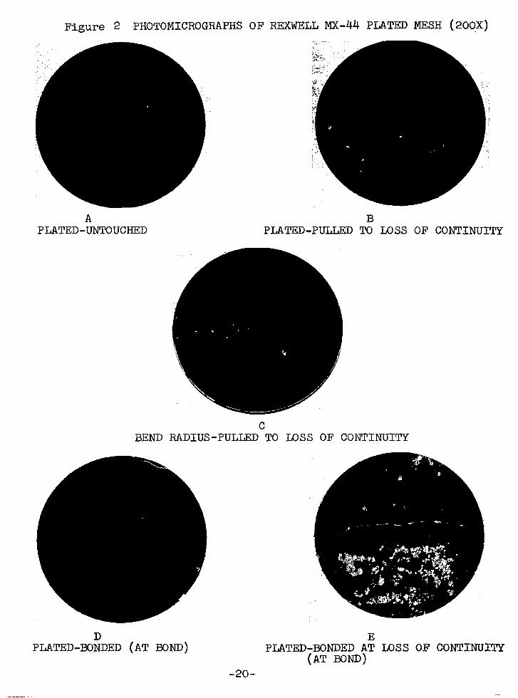
Figure 2 PHOTOMICROGRAPHS OF REXWELL MX-44 PLATED MESH (209X)
A B PLATED-UNTOUCHED PLATED-PULLED TO LOSS OF CONTINUI TY
BEND RADIUS-PULLED TO LOSS OF CONTINUITY
PLATED-E$DED (AT BOND) PLATED-BONDED A; Tx)SS OF CONTINUI (AT Born)
-2o-
:TY

The flnai material investigated was polyethylene film.
The type of film looked for was one that could be produced in
various thicknesses, all of which were less than l'mil and
biaxially oriented. Ordinary polyethylene film is unlaxially
oriented and has poorer physical properties in the direction
perpendicular to extrusion than in the direction of extrusion.
Thus, a biaxially oriented polyethylene film was custom-made
to meet the above conditions. The film is a biaxially oriented,
intermediate density polyethylene film manufactured by
Sea Space Systems, Inc., Torrance, California. Due to scheduling'
and procurement problems, mainly based on funding and time
limitations, it was decided to use this 1 mll, intermediate
density biaxially oriented polyethylene film* for the
construction of the deliverable items and for preparing samples
.for the testing program. The properties of the film are listed
in Table 4,
A research and design study later showed that a
0.30 mil film would be adequate for the satellite in question.
Results show that the intermediate density polyethylene film
possessed superior strength compared to a similar low density
film and that this material was also a superior acceptor of an
electroless copper plate. Following this testing, fabrication of
test models was Initiated usi'ng the 1 mil material. It should be
kept in mind that 0.30 mil material would be used in the actual
fabrication of the 425 foot diameter passive communications
satellite. It must be noted that test results obtained on the
1 ml1 material can be safely extrapolated to an 0.30 ml1
material since both materials would be made out of the same
*From hereon in called "PE 12" -21-

Table 4
Physical Properties of Sea Space Intermediate Density, Polyethylene Film (PE 12)
1 Mil, Biaxially Oriented
=Y % E Tm P Mn Direction Idegrees) (psi x 103) (psi x 103) (psi x lo31 ("c.) (gms./cc.)
0 0,94~0,03* 2.3$O.i3 2g.2f2.2
0.87h.04 2.00fo.11 26.2k.5 116.5** ***
45 0.931 16,000
90 o.g4:0.04 1.65fO.07 33.d3.2
"Y = Yield Stress
' u %
= Ultimate Stress U
I E = Modulus of Elasticity Tm = Crystalline Melting Point
p = density M = Number Average Molecular Weight
n
* All tensile tests performed on a Table Model Instron with a strain rate of 2 ln./mln,, 5 lbs. full scale load. Full tensile testing procedures discussed in Appendix I.
** The average result of three crystalline melting tests presented in Appendix II.
+** The average of the density given by the manufacturer and tests run on density gradient apparatus described in Appendix III.

resin and would have the same processing history and the only
difference would be in thickness.
Sea Spacers biaxially oriented polyethylene films are
produced in a cylindrical extruder with an annular tube of
polyethylene filmemerging from the dies. The tube is blown
with air from the inside creating a pressure in the tube, The
complete details of the production of biaxially oriented film
is spelled out in detai 1 in another NASA report. 4
The biaxial orientation results from the fact that internal
pressure produces membrane stresses in the film In the radial
direction (transverse direction, 90' direction). This Is in
addition to the usual stresses created in the machIne direction
(extrusion direction, O" direction) due to the fact that the
film Is being drawn out of the extruder under stress.
-23-

2.0 MATERIAL PROPERTIES DEVELOPMENT PROGRAM
Prior to specifying the required properties of the film
to be used in construction of the 425 foot diameter satellite
the three areas indicated below were critically investigated.
1. Extraction Study - This study was undertaken in an
attempt to decrease the weight of crosslinked polyethylene film
to be used for construction of the sphere without detracting
from the film's physical properties. To this end the low weight
fractions of crosslinked polyethylene were extracted with a
suitable solvent to lower the area weight of the crosslinked film.
2. Development of a Laminate - Calculations and preliminary
tests indicated that the stiffness of copper metallized poly-
ethylene film increases dramatically with the addition of a small
weight fraction of a copper plate to the total film weight.
The effects of varying the thickness of copper metallized to
varying thicknesses of polyethylene were therefore critically
investigated to obtain a laminate of low weight 'and high stiffness,
3. Perforation Study - The deployment of a space structure
via the memory effect has a distinct advantage over deployment
mechanisms using inflatants. This advantage is due to the
ability of deploying film which is perforated. The use of
perforated film is two-fold, it decreases the effect of solar
pressure, and materially decreases the weight of the deployed
sphere. Therefore, because of the Importance of perforation a
thorough study was conducted on the effect of perforation on
laminate weight, stiffness and electrical resistance.
2.1 Extraction Study
The primary goal of the extraction study was to develop
a polyethylene film with an E/p value higher than currently
-24-

available. To this end, polyethylene film was irradiated
to from 5 - 75 Mrads using beta radiation to impart varying
degrees of crosslinking. It was subsequently extracted in a
suitable solvent.
The modulus of elasticity, E, and density, p, of the
extracted film were then measured and compared with unextracted
and unirradiated material. Test results showed that the
crosslinked, extracted polyethylene did not improve the strength
sufficiently, to realize any significant increase in E/p.
Additional work incidental to the extraction study yielded
valuable information regarding minimum radiation dosage required
for crosslinking and the effect of dosage on the strength of
extracted polyethylene.
2.1.1 Variation of Strength with Dose
Instron tensiles have been determined on samples of
1 mil standard density polyethylene film irradiated to from
5 to 75 Mrads. The results, see Table 5, indicate only modest
changes in E. In fact, in some cases a slight decrease with
dose in the 0' direction is observed.
2.1.2 Solvent Tests
Samples of unirradiated polyethylene were extracted
for one day in the various solvents at 100°C. f 2'C. The
results of these tests are listed in Table 6 below.
These results indicate that solvents with little or
no.polarity are the best solvents for extracting polyethylene
which is itself mainly a saturated substance. The solution of
the polyethylene at 1OOOC. i 2'C. by the first three solvents
indicate that they are very acceptable solvents for polyethylene
extractions. Xylene was used in all subsequent extraction
experiments. -25-
LL ----

5 Table
Effect of Radiation* Dose on the Strength** of 1 Mil Standard Density Sea Space Polyethylene Film
0 degrees 90 degrees Dose Modulus of Elasticity, E Modulus of Elasticity, E (Mrads) (psi x lOf3) (psi x 10'3)
5” 10 15 26 ;; 1 f 2.1
f 212 30.7 *
2615 0.9
;22 +04
24.3 +, 1.2 f 1.0 29.8 f 1.6 39:4 *
$ - f f
2:5
gz.2 . 1.0 1.0 27.8 29.0 i..i 0.3
* Irradiated In Nitrogen, Heat Treated in Nitrogen
** Determined by Instron Tensile Test. Strain rate: 2.0 in./min. Temperature: room temperature
Table 6
Extraction Efficiency of Various Solvents on Polyethylene
Solvent Type $ Extracted*
Decalin Tetralin Xylene 0-Dichlorobenzene Butyric acid
Unsaturated Saturated Aromatic Aromatic-Polar Polar
Dimethyl formamide Polar i:g: Dimethyl sulfoxide Polar -0.19
*$ Extracted = $ dissolved
-26-

2.1.3 Extraction
The low molecular weight fractions In the irradiated
polyethylene film samples were extracted In xylene at 1OO'C.
over 4 days. The Q-day time was selected since other studies
at these laboratories 5 indicate this would Insure complete
extraction of uncrosslinked material. In addition, the antl-
oxidant n-beta-phenylnaphthylamine was added to each solvent to
retard oxidation of the polyethylene during extraction.
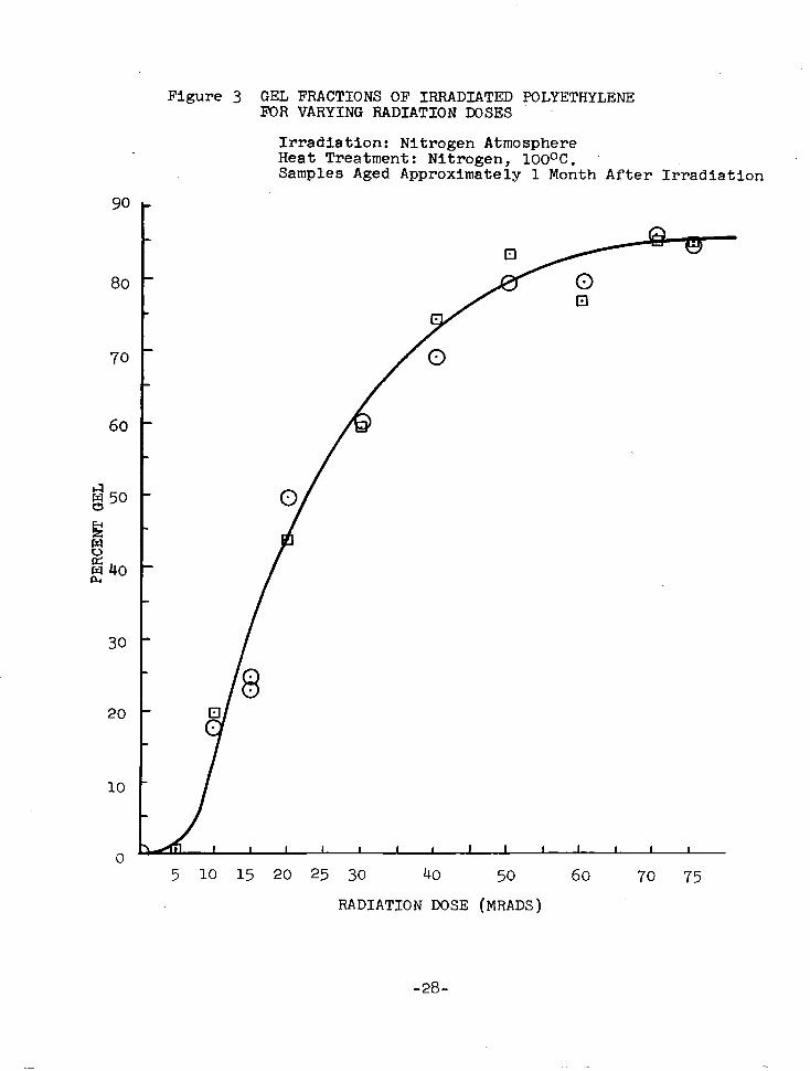
2.1.4 Gel Fractions
As part of the extraction study and in general for
all Irradiation crosslinking done in the contract it was
necessary to know at what doses crosslinking occurred. The most
effective way of determining the effect of irradiation on the
crosslinking of a polymer is to determine its gel fractions, I.e.,
weight of non-extractible material wt. gel weight of unextracted material = wt. sol
The gel fractions obtained after extraction of samples lrradi-
ated to various doses are plotted in Figure 3. It can be seen
from the curve that pronounced gelation (crosslinking) occurs
after 10 Mrads of irradiation. This result gives further
verification that a dose of 15 Mrads Is satisfactory for
sufficient crosslinking. The curve furthermore shows that at
ca. 75 Mrads the materials approach a constant maximum gel
of 85s.
2.1.5 Strength Dose Variations of Extracted Material
Tenslles have been determined on samples of 1 mil
standard density polyethylene film given various doses of
irradiation and were then extracted. The resulting tensile
tests obtained on samples parallel to the extrusion (i.e.,
0' direction) are given In Table 7 and In Figure 4. -27-
I--
90
80
70
60
g50
!s 8 g40
30
20
10
0
Figure 3 GEL FRACTIONS OF IRRADIATED POLYETHYLENE FOR VARYING RADIATION DOSES
Irradiation: Nitrogen Atmosphere Heat Treatment: Nitrogen, 100°C. Samples Aged Approximately 1 Month After.Irradiation
5 10 15 20 25 30 40 50 60 70 75
RADIATION DOSE (MRADS)
-28-

Table 7
Effect of Complete Extraction* on Strength of 1 Mil Standard Density Sea Space Polyethylene Film Given Various
Doses of Radiation**
Dose (Mrads)
Modulus of Elasticity, E (psi x 103)
Extracted in xylene at 1OO'C. for 4 days with 0.1% n-beta-phenylnaphthylamine
Irradiated in Nitrogen, Heat Treated in Nitrogen, 1OOOC.
It is seen that there is some increase in strength
over untreated film. The fact that the strength has not
increased significantly can be attributed to some degradation
occurring during irradiation and during extraction.
2.1.6 Dens-ities of Extracted Polyethylene Film
The densities of crosslinked-extracted standard
density (0.92 gm./cc.) Sea Space polyethylene film, hereinafter
called "PE 11" were determined using the density gradient
apparatus described in Appendix III. The film samples were
irradiated to from 5 to 75 Mrads and were extracted in xylene
at 100°C. The values of the new densities of the extracted
material are given in Table 8 below.
It can be seen from the results of this experiment
-eg-

30
28
24
20
a
Figure 4 EFFECT OF COMPLETE EXTRACTION ON STmNGTH OF 1 MIL STANDARD DENSITY SEA SPACE POLYETHYLENE FILM GIVEN VARIOUS LOSES OF RADIATION
Irradiated in Nitrogen Heat Treated in Nitrogen, 1OO'C. Extracted in Xylene at 1OOOC. for 4 days with 0.1% n-beta-phenylnaphthylamine
10 20 30 40 50 60 70 75 80
RADIATION DOSE (MRADS)
-3o-

that an extraction technique does not lower the density of
the polymer and in fact increases it somewhat. The increase
Is probably due to further alignment and collapsing of the
molecular chains. It is believed, frqm the results of these
tests, that extraction will not lower the density of irradiated
polyethylene film.
Table 8
Densities of Extracted-Crosslinked PE 11
Dose (Mrads)
O(Unextracted)
i;
65: 70
dgm./cc. 1
0.920 0.941 0.943 0.932
:*;;i5 0: 932
2.1.7 Results of Extraction Program
It is seen from Figure 4 that the strength of
extracted, crosslinked polyethylene does not increase very much
above that of untreated polyethylene. In fact, in some instan.zes
it actually decreases. Additionally, it was found that the
densities of the extracted material did not decrease, see Table 8.
With these results it can be concluded that irradiation-extraction
treatments do not increase E[p.
2.2 Development of Laminate
To determine the specifications of the film to be used
to construct the satellite, it was necessary to establish the
proper film density and type and the metal thickness that would
result in a laminate low in weight and sufficiently rigid to
withstand five times solar pressure when fabricated as a
-3l-

425 ft. diameter sphere. The program proceeded by electrolessly
plating a complete thickness range of polyethylene films to a
given metal thickness and then determining if (a) the laminate
was low In area weight, and (b) if the sphere made from this
laminate could withstand five times solar pressure. It was
found after considerable trial and error that a 15 x 10 -6 in.
coat of copper on both sides of polyethylene film was necessary
so that a thin polyethylene film (for low weight) could be used.
2.2.1 Flexural Rigidities of Metallized Polyethylene Film
In an effort to lower the required thickness of
the polyethylene-metal laminate, experiments were run where
both sides of thin polyethylene film were plated. Polyethylene
films of various densities and thicknesses were electrolessly
plated with copper In thicknesses from 5 x 10 -6 to 15 x lo+ inches
on both sides. Flexural rigidities of the plated films were
determined. using the Standard ASTM D 1388-55T Beam Cantilever
Test for flexural rigidity by measuring the length of overhang.
The ASTM beam cantilever test is a test designed to measure the
flexural rigidities of films and fabrics. It has been success-
fully used to measure flexural rigidities of similar thin film
laminates before and has been proven to be an accurate test. 6,7
A description of the experimental procedures used to measure
flexural rigidities is given in Appendix IV.
Flexural rigidities, GL(t) were calculated as
follows:
-32-

GL(t) = wA(Ag)3 (3)
where lF = length of overhang of
WA = area weight of plated
= area weight of film + copper film
plated film
film
area weight of deposited
= (density of the film + (density of copper
thickness of film) thickness of copper film)
= PFt + PcUtcu
where P cu = 8.9 gm./cc.
PF = 0.920 ~IIL/CC., 0.931 m./cc.
For a number of test samples:
(4) -L where Go = average flexural rigidity in O" direction
CL = 90
average flexural rigidity in 90° direction
2.2.2 Flexural Rigidities of PE 11 (Plated) Type Films
Standard density (0.920) polyethylene films, ranging
in thickness from 0.15 mil to 4 mils, were electrolessly copper
plated to a depth of either 5 x 10m6 or 10 x 10 -6 inches on
both sides. Lengths of overhang were determined and the flexural
rigidities were calculated.
The results are given in Table 9 below and are
plotted in Figure 5, curves A and B.
2.2.3 Flexural Rigidities of PE 12 (Plated) Films
Samples of PE 12 film (0.931) plated with 5 x 10B6
Inches or 10 x 10m6 inches of copper were tested for flexural
rigidity. It was found that the higher density plated film gives
a considerably higher flexural rigidity as compared to the
-33-

0.15
0.21
0.30
0.55
1.00
2.85
4.00
*lb.in,
Table 9
Flexural Rigidity as a Function of Film Thickness with Electroless Plating Time as a Parameter
c 0 ago
lb.in.xlO -6* lb.in.xlO -6*
1.293 1.635 1.45
1.442 0 .%i’ 1.18
2.566 1.837 2.17
3.911 3.174 3.52
18.686 24.937 21.58
146.8 168.7 157.5
678.4 702 689.9
= lb.in.2/in. since samples are 1 inch wide
Minute Plate 1Q Minute Plate .
e
lb.in.xlO -6*
1.341 1.010
1.460 1,007
2.385 2.464
3 319 8.572
37.89 18.26
247.9 339.2
929.6 743.7 - Y
lb.in.xlO -6*
1.16
1.21
2.42
5.72
26.30
299.0
831.0

plated standard density film. In addition to the higher density
material, having a higher modulus of elasticity, It also gives
a surface that is more receptive to the metallization process.
This is evident from Figure 5 where the flexural rlgiditles of
the plated PE 12 are compared with the flexural rigidities of
the plated 1-mil PE 11.
2.2.4 Flexural RigiditieS of Plated PE 12 Film over the Complete Range of Film Thicknesses
The necessity of a stiff film at low area weight
prompted the use of PE 12 as the base material, It was plated
to a depth of 15 x 10 -6 in. on each side. The flexural rigidity
thickness curve for this laminate was then constructed. Use
was made of the flexural rigidity of plated 1 mil PE 12 to give
the displacement above the low density curves. Its contour was
determined using the low density curves. The "limiting" points
for the flexural rigidities were experimentally determined. For
the upper point a 2-mil laminate of PE 12 plated to a 15 x 10 -6
inch depth on each side was used while the lower point was
determined using a 0.15 mil PE 11 film plated to 15 x 10 -6 in.
thickness on each side. PE 11 film could be used for the lower
point because the type of polyethylene film becomes less
important as the polyethylene film thickness becomes very small,
since it only contributes a small fraction of the flexural
rigidity of the laminate. This is shown in curve D of Figure 5,
where the flexural rigidity of unplated, standard density film
is plotted vs. thickness using the beam cantilever test data
(listed In Table 10). The final flexural rigidity-thickness
curve constructed from the three data points and the contour
of the 5 x 10 -6 and 10 x 10 -6 in. thickness curve is given
-35-

Flexural Rigidities unplated PEll type film
A @ PEll plated to PEll plated to
5X10⁻⁶ in. both aides loJclo-6 In. both sides
,PEIZ plated to 15x10-6 In. both sides
0 1 2 F& THICKNESt 6 .7 t (MI=)
F * -36-

in Figure 5, curve C. The extrapolated flexural rigidities
given by curve C will be used to determine the polyethylene
thickness needed to withstand five-times solar pressure, and to
determine the satellite weight. The calculation is carried out
in Section 3.2.~ to follow.
Table 10
Flexural Rigidity of Unplated PE 11 vs. Thickness
t G* (mll) (lb.in.2/in. x 10 -6)
0.15
0.21
0.30
0.55
1.0
2.85
4.5
* Arithmetic mean reported
No reading obtainable
o .0567
0.2431
1.226
2.30
al.714
1%. 155
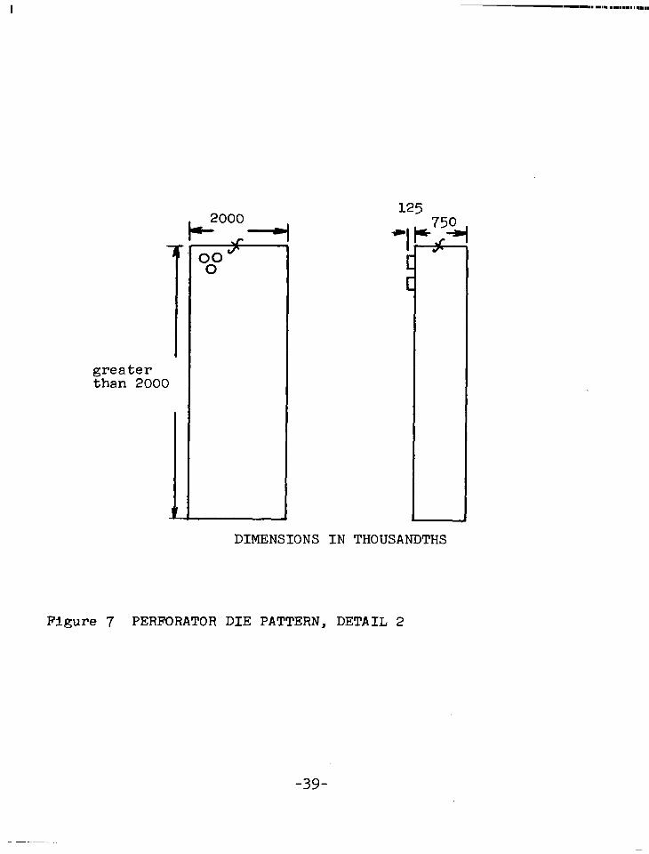
2.3 Perforations
In order to test the effects of perforation (fraction
open area) on flexural rigidity and resistance of metallized
film a perforation study was initiated. Samples of polyethylene
film were perforated to 10, 20 and 40% open area using small
perforation dies made at NASA, GSFC. The die patterns are shown
in Figures 6 and 7, and Table 11. A staggered circular arrange-
ment has been chosen because it is known that a staggered
pattern has been found to possess more rigidity than a pattern 8
of uniform rows. It should be additionally pointed out that
staggered hexagons give higher rigidity than staggered circles, 9
-37-

Ll CD I
++2y -+.-2y cf CUTTING EDGES
4L” z - ‘r
.l"D
I, ! s
-.-mm -.-mm II II - -
- -
-, - - - -
- -
DIMENSIONS IN THOUSANDTHS
Figure 6 PERFORATOR;DIE PATTERN, DETAIL 1 (Dimensions In Table 11)
2r = 0.1 X =0.866(R+0.1) .Y = (1+0.1) /
2 2 =X
2
greater than 2000
DIMENSIONS IN THOUSANDTHS
Figure 7 PERFORATOR DIE PATTERN, DETAIL 2
-39-

however, it was found in the design'study to follow that
staggered circles are quite adequate for the goals of the project.
It was found that flexural rigidity and electrical resistance
were significantly better if the film was perforated before
metallization. Tests were run both ways. All samples were
made from 0.30 mil standard density polyethylene film metallized
with 15 x 1O-6 in. of copper on both sides. This particular
laminate configuration was chosen, since this configuration was
found to be able to withstand five times solar pressure using
a buckling pressure-thickness calculation which is presented
in Section 3.0 to follow.
Table 11
Perforator Dimensions
1 a
0.10 0.2012 0.2608 0.1506 0.1304 6 0.2470
0.20 0.1129 0.1844 0.1066 0.0922 7 0.3613
0.30 0.0739 0.1506 0.0870 0.0753 9 0.3044
0.40 0.0506 0.1304 0.0753 0.0652 10 0.3223
0.50 0.0347 0.1167 0.0674 0.0584 11 0.3264
2.3.1 Flexural Rigidity of Perforated Film
The flexural rigidsties of perforated film were
measured in the same way unperforated film was measured see
Section 2.2.1. The only difference is that equations (3) and
(4) are modified as follows:
-4o-

and
GL(t,Fv) = (1-Fv)WA 2
/'cL(t,Fv) = (1-F
(5)
(6)
The results of the study for plating, then perforating and
perforating, then plating are listed in Table 12 and plotted
in Figure 8.
2.3.2 Electrical Resistance of Perforated Film
Electrical surface resistances (in ohms/sq.) were
measured across samples of perforated, metallized film and
metallized perforated film. The resistances reported were
the average of resistances measured in two directions according
to the following diagram:
, al OO
- "*o" b
000 0
where w 1 =- SC! 2 (7)
I .-- --

Table 12
Effect of Perforation on 0.30 Mil Plated Standard Density Polyethylene Film
Percent Open Area
Go (lb.in. x 10m6) G 9. (lb.ln. x 10w6) A G(lb.in. x 10m6)
Plated for 15 Minutes then Perforated
0 13.476 10 20 a*;;: 40 4:510 50 0.835
Perforated and then Plated for 15 Minutes
0 13.476 2': 11.162 9.487
40 5.532
12.206 12.826 10.680
Ebb ;-z;
o: 899 4:667 0.866
12.206 12.826 5.773 7.138 :*;z;
12.498 8:315

4 12
11
10
-9
$8 ii---- g 7 .
36 V ” 5 0 d x4
<! 3
0 0.30 mil plated, perforated
a-- 0 0.30 mil perforated, plated \
\ \
\
\ \ \
\ \
\
\ \
\ \
\ \ \
\ \ \
10 20 30 40 50 6;
PERCENT OPEN AREA (F,)
Figure 8 FLEXURAL RIGIDITY OF PERFORATED 0.30 MIL STANDARD DENSITY POLYETHYLENE FILM VS. PERCENT OPEN AREA (Plated to 15 x 10s6 inches on both sides)
-43-
1. -

The results of the resistance measurements are tabulated
in Tables 13 and 14 below.
Table 13
Resistance of Plated (15 x 10B6 in. Cu) Perforated, Standard Density Polyethylene Film
Percent R//
a Open Sample sq Area Size (ohms) ohms) ohms/sq.
0 3x5 0.275*
10 2x5 2.05 0.25 0.72
20 2x5 2.32 0.59 1.19
40 2x5 15.40 3.81 7.85
50 2x5 281.00 634.00 logo.8
9 Average of resistance values from each sample before perforation (the sample size was 3x5).
Table 14
Resistance of Perforated-Plated (15 x 10 -6 in. Cu) Standard
Density Polyethylene Film
Run 1 Run 2 Percent Open Sample R// 2 "// FL
K sq
0()()()(/q) Area Size ohms ohms ohms ohms ohms s .
0 2.7;
10 3x3 0.6 0.6 0.65 0.6 0.61
20 3x3 0.6 0.6 0.6 0.6 0.6
40 3x2 run 1 I I 2x2 run 2 1.2 0.4 0.8 0.8 0.8
*Since the film was perforated first, the resistance value for 0% open area from Table 13 is used.
-44-

2.3.3 Conclusions-on Perforation Tests
It can be seen from the perforation tests summarized
in Figures 8 and 9 that metallizing the material after perforation
as opposed to before perforation results in a material with
considerably better properties. Apparently the perforation
procedure distorts and stresses the circular boundaries it
punches out. This may be seen from the bottom photomicrographs
of Figure 56 in Section 6.1.
If the copper is applied before perforation, it along
with the plastic is distorted and cracked when perforated. If
the copper is applied after perforation it is unharmed and even
corrects some of the distortion and weak spots in the plastic
around the hole boundary by filling in small tears and cracks.
Since there are no additional problems involved in electroless
metallization of perforated film as opposed to a non-perforated
film it was decided to metallize after perforation. The
flexural rigidity of the laminate decreases with perforation.
This is shown in Figure 8, Curve B, which is further used in
the perforation optimization study to follow in Section 3.0.
-45-
I .-- -

1000 Curve A: # . w a 0.30 ml1 plated, perforated A I -
P
a O.XImil perforated, plated B
c c;': cn 1o.c v-
!x
1.c
I
1 0.1 I 1 1 1 , 0 10 20 30 40 50
CURVE A
PERCENT OPEN AREA (F,) Figure 9 RESISTANCE (n/SQ.) OF PERFORATED 0.30 MIL STANDARD DENSITY
POI.YETHYL,ENE FILM VS. PERCENT OPEN AREA (Plated to 15 x 10-6 in. Cu on both sides)
-46-

3.0 BUCKLING PRESSURE - THICKNESS STUDY
A literature search, an experimental program and
calculations for the design of a 425 foot diameter sphere
capable of withstanding a buckling pressure of five times solar
pressure (Ps = 1.3 x 10-g psi) were completed during this
investigation. .The total weight of the proposed sphere is
less than 1000 lbs. The design which follows is based on the
application of a thin polyethylene film as the material of
construction. This material has been irradiated and contains
a memory. The design study has been divided into three stages.
The first stage was concerned with developing an equation which
would yield a critical buckling pressure - thickness relationship
for the configuration under study. In the second stage the
equations developed during the first stage were modified to
account for the effects of the applied copper laminates.
Finally, in the third stage the experimentally determined effects
of perforations were included in the equations and the satellite
weight was optimized with respect to fraction open area.
3.1 Theoretical Equation
The classical equation derived for determining the
critical buckling pressure as a function of thickness, t, of
a thin spherical shell is given as follows: 10,ll
4 P 2Et = --XL2 t
cr R(l-v2) R 2 R2 1 (8)
where E = the modulus of elasticity v = Poissonls ratio R = Radius of sphere
-47-

For a large sphere with a thin shell
So equation ( 8)
P = cr
or t=
In equation (9 )
E = 20
t2
may be simplified as follows:
2 Et2 R2 34(1 - v2) h
3+(1-v2)t~
if the following values are chosen:
x 10 3 psi
(9)
P cr = 5(1.3 x 10-g psi)
R = 2550 inches
v = 0.50
t is found to equal 0.104 mil.
It is found that the classical buckling pressure
equation-yields low values when the t i? ratio is less than 10W3.
Summaries of the inaccuracy of using theoretical buckling
pressure equations for large thin shelled spheres are given
in Theory of Elastic Stability and Formulas for Stress and Strazin.
They are,respectively, as follows:
"Experiments with thin spherical shells subJected to uniform external pressure show that buckling occurs at pressures much smaller than that given by equation (8 ).....I( (ref. 12)
"Because of the greater likelihood of serious geometrical irregularities, and their greater relative effect, the critical stresses actually developed by such members usually fall short of the theoretical values by a wider margin than in the case of bars...... The critical stresses or loads indicated by any one of the theoretical formulas should, therefore, be regarded as an upper limit, approached more or less closely according to the closeness with which the actual shape of the memb:r approximates the geometrical form assumed . . . . .
-48-

continuea
3.2
g ratios,
Rourk additionally states that this discrepancy
to increase with the thinness of the material. 13
Spherical Cap Models
Since the theoretical approach is inaccurate for small
equations have been used based upon models of spherical
f cap sections with small fi ratios. The methods used in the
following sections will separately compare required thicknesses
based on two models. One model is a uniformly loaded cap
section, the other model is a point loaded cap section. For
comparison the calculations have been performed without a
material correction factor as well as with one.
3.2.1 No Material Correction Factor
3.2.1.1 lJnifor@y Loaded Cap Section
Articles by Reiss, 14 and Reiss, Greenburg and
Keller15 .dealing with the buckling of uniformly loaded
spherical cap sections of small curvature, determine critical
buckling pressures for spherical caps of various geornetrles.
The results given in the articles and which are plotted as
P cr - in Figure 10 were determined both numerically and x2
experimentally. The critical buckling pressure is given in
non-dimensional form:
P PO,(P) =
or P cr A= t2
.*.P,,,(P) = U(P) (10)
-4g-

P Figure10 THE FUNCTION U(p) = $-
U INCHES

where P err(P) = non-dimensional buckling pressure
P cr = actual buckling pressure (= 6.5 x 10-g psi)
k+l - ‘2) (=0.50)
v = Poisson's ratio (=0.50)
t = film thickness
R= radius of spherical cap (=2550 inches)
E = modulus of elasticity (= 20 x 103 psi)
The non-dimensional buckling pressure PC,, is plotted against
a non-dimensional geometrical parameter defined as
where r is equal to the radius of deformation, see Figure 11 .
It is convenient to plot Pcrit2 against p for all
modes of deformation (caps with different geometrical parameters
deform in different ways 16) . The results are given in
Figure 10. It can be seen from this curve that P varies
between 40 x 10 -4 -4 cvt2
and 80 x 10 . For a critical buckling
pressure of 6.5 x 10Wg psi this range corresponds to a thickness
ranging from 0.902 x 10⁻³ in. to 1.275 x 10⁻³ in.
3.2.1.2 Point Loaded Cap Section
A point loaded spherical cap model has been used for
the following reasons. A point loaded force gives a more severe
test than a uniformly distributed force (a pressure). The point
loaded model will thereby give the designer an additional
factor of safety when the thickness is determined. Furthermore,
a point load results in a "dimple like" failure which is the
type of deformation observed in the buckling of thin spherical
shells, 17 18
In a text by Biezeno and Grammel -5l-
critical buckling

pressures have been theoretically determined for spherical
cap sections of various geometries. The results are given
in terms of a loading parameter ( p ) versus a geometrical
parameter ( x ). They are defined respectively as follows:
RFcr p= - Et3
r4 x= - t2R2
(12)
(13)
where F = critical buckling force. cr
If 'cr is concentrated as a force, Fcr, at a point
on the center spherical cap, then
F = 2 cr rir PC, (14)
This transformation is shown in Figure 11.
F cr
Figure 11 : TRANSFORMATION FROM DISTRIBUTED LOAD TO POINT LOAD -52-

18 From the graph ofv and x in Engineering Dynamics,
CI may be represented by the equation:
CI = \1 0,093( x+ 11.5) -0.94 91 x 10-2 x + 1 (15) It should be noted that at X7500 the approximation
of equation (15) gives a high value of I-I which will provide an
additional factor of safety for the designer. If equations
( 11) - (15) are used to solve for Per in terms of p and t
the following equation is obtained:
P cr = 10-2k p + 1
4 P 1 t2
Or 'cr -= F’(P) t2
( 16)
whereF(p)= 2E1 10'2k p + 1 - IT R2kn 4 P 1
F(P) = F was then plotted versus p, see Figure 12. Since
the value of the geometrical parameter is not known for this
system, the value of p which gives the minimum F(p) was chosen.
In this way, the maximum value of t will be obtained. The
result is as follows at p = 30, 'cr is a minimum. At the
P t2 minimum cr
F' t is found by solving equation (16); the
result is 1.85 x lo-3 inches.
3.2.2 Calculation with Material Correction Factor
The above calculations have not taken into account
the added resistance to buckling due to the thin copper
laminations on the polyethylene film. If equation (12) is
combined with equation (14) it is seen that PC, is proportional
to Et3. This suggests that Per is proportional to the
-53-

Figure 12 THE FUNCTION F(P)
F(P) = 2 E TI R2 k$
(
F(P)
(POLYETHYLENE)
10’*kP + 1. )
4 P E = 20 x 103 R 1 '05;: INCHES k .

flexural rigidity eL(t) of the laminated film since
^cL(t)W EI =Et3. An experimental flexural rigidity used
as a correction factor additionally will correct for any
imperfections in the film (such as microscopic cracks) since
the imperfections will be reflected in the experiment. It also
suggests that the actual Per is proportional to the ratio of
the actual laminate flexural rigidity to the flexural rigidity
of the unlaminated film (aL(t)/ 2 Et3). It is in this way
that the above buckling pressure equations have been corrected
for the effect of the increased resistance to buckling by the
added thickness of copper.
It was assumed for a thin film laminate of copper and
polyethylene that increasing the copper thickness a small amount
and decreasing the polyethylene thickness a large amount can still
increase the rigidity of the laminate. This is so because of a
very high modulus of elasticity of the copper compared to the
polyethylene. Various combinations of thicknesses of polyethylene
and copper ranging from 0.15-1.5 mil and 5 x 10m6 - 15 x 10B6 in.
respectively were therefore investigated (see Section 2.2).
It was found that after considerable trial and error
(Section 2.2.3) that 15 x 10-o in. of copper was necessary to
achieve sufficient flexural rigidities to withstand calculated
solar buckling pressures and still be within design weight
limitation. For the above reasons the experimental flexural
rigidity curve of Figure 5 has been used in the correction
factor in the following calculations.
3.2.2.1 Uniformly Loaded Cap Section
If the critical buckling pressure in equation (10)
-55-

is corrected for rigidity using the factor
fzL( t) &Et3
the following equation results
P = SL(t) cr &Et3
aPIt
or H(t) = @ Cl?
t where H(t) = -
%L( t)
(17)
Solutions to equation (17) can be found using
Figures 10 and 13 . The solutions are only obtainable
at critical buckling pressures greater than 6.5 x 10-g.
Table15below indicates the solutions for maximum and minimum
U(p) at the closest buckling pressures to the 6.5 x 10mg psi
specified.
Table15
Soluticns to Zquation (17)
U(P) max H(t) P
Cl- t
minimum 40 x 10-b 62.5 38.4 x lCg 0.15 -3 x 10 maximum 80 x IO-~ 62.5 76.8 x 10'~ 0.15 x 10 -3
The results presented in the table above indicate
that a film thickness of 0.15 x 10 -3 in. can withstand critical
buckling pressures of ca. 6 to 12 times the required pressure.
This means in effect that the 0.15 x 10m3 in. thick film can
well withstand PC, = 6.5 x 10 -9 psi of pressure or a film
thickness of less than 0.15 x 10 -3 in . can withstand
P cr = 6.5 x 10'~ psi. -56-

, ,
H
Figure 13 THE FUNCTION H(t) = t fzL( t)
where eL(t) is the flexural rigidity of the laminated film given In Figure 5 curve C,
1 0 .2 .4 .6 .a 1.0'1.2 1.4 1.6 1.8 2.0 2.2 2,4 2.'" c." =.v
t(IN. x 10-3)

3.2.2.2 Point Loaded Cap Section
An approach-using a point loaded cap section as a
model-believed to be conservative for design purposes, has been
used to determine the composite film thickness that will
withstand the specified buckling pressure of five-times solar
pressure. The approach consists of modifying equation (16)
the basic buckling pressure equation for the effect of small
film thickness and the effect of metallic laminates. The
method used corrects equation (16) for actual film-metal
laminate flexural rigidity by the application of,the following
factor
where BL(t) is the measured flexural rigidity of the metal-
plastic film laminates and & Et3 is the flexural rigidity
of the polyethylene alone. If the flexural rigidity correction
factor is applied to equation (1.6) the following equation
is obtained:
If equation (18) is rearranged as follows: P -I
with
(18)
and the following function defined
Fc(d = qp+q n R2kzP
-58-

equation (18) may then be stated as
H(t) = F%d (19)
with H(t) plotted in Figure 13 from the experimental values of % G (t) given in Figure 5, curve C, and with the function
F'(p) plotted in Figure 14, with the constants Per, R and k
additionally listed, equation (19) has be.en solved graphically
for film thickness for various values of p. The results are
summarized In Table 16.
Table 16
Polyethylene Thickne Equation (19) (15 x lo- z
ses of Composite Film - Solutions to inches of Copper Plate on both sides)
P -F'(c) = H(t) t x lo3
5 53 0.17 10 29 0.18 g: 18.1 18.6 0.29
100 36.0 2% 199.5 0:15 199.5 40.15
It is apparent from the above Table that the maximum
thickness of polyethylene film corresponds to the minimum F'(p).
At min F'(p) = 18.1, t = 0.30 x lo -3 in .
3.3 Comparison of Derived Film Thicknesses
Table 17 summarizes the values of the film thickness
for the various methods of calculation.
It is believed that the 0.30 film thickness Is the
most reliable of the five calculated thicknesses. Use has
been made of the experimental flexural rigidity values of the
actual material; and flexural rigidity is a key property in
determining a material's resistance to buckling pressure. In
addition, the use of a point load instead of a uniformly
-59-

Figure 14 THE FUNCTION F'(p)
F'(p) = 241 ( TT R2 ksPc,
F’(P) with R = 2550 Inches
10-2kp + L ) 4 P
k = 0.50 P,, = 6.5 X W4 Psi
P
-6o-

-
Table 17
Derived Thickness of Polyethylene Film
Material Model Load Composite Material Thickness
Rigidity Correction Factor Eq. in. x 10-3
1. Polyethylene Sphere Uniform (Per) None (8) 0.104
2. Polyethylene Spherical Uniform (Per) None Cap Section
(10) 0.92-1.275
3. Polyethylene Spherical Point (nr2Pcr) None Cap Section
(16) 1.85
4.
A P ’ 5.
Polyethylene Spherical (+15x10-6 in. Cap Section Cu both sides)
Cu both sides)
Uniform (PC,)
Point (nr2Pcr)
flexural rigidity of COinpOSite film - flexural rigidity of film
flexural rigidity of composite film - TIexural rigidity of film
(17)
(19)
0.15
0.30

distributed load creates an additional safety factor, since
a point load is a more severe condition.
3.4 Perforation Optimization - Satellite Weight
-3.4.1 Satellite Weight vs. Void Fraction
With the point loaded spherical cap model established
and an equation derived which accounts for the effect of the
copper laminate, a polyethylene film thickness of 0.30 x 10⁻³ in.
was calculated. The weight of the non-perforated satellite was
then determined:
Polyethylene
Density Thickness Area Wei ht (lb./ft.3) (in.) (lb./ft. 5)
58.16 0.30 x 10 -3 1.454
Copper (electroless) 472.50 2(15 x 10-6) 1.180
TOTAL . . . . . . . . . . . . . . . . . . . . . . . . . . . . . . . . ..*............... 2.634
For a sphere with a diameter of 425 ft. the surface
area is 567,344 ft.2 With a composite area weight of
2.634 lb,/ft.2 the total weight of the non-perforated sphere
is 1494.384 lbs.
The effect of perforation on the weight of the
satellite can be seen from Table 18.
Table 18
Satellite Weights - Perforated Film Thickness: 0.30 ml1 Metal Thickness: 15 x 10-6 in. (both sides)
Percent Open Area
85
ii ? :
2:
10
Total Weight (lbs.)
224.157
:79; l :;i 597:754 747.192 896.630
1046.069
;;zp5g . - -

Since flexural rigidity decreases with Increasing percent
open area and the effect of buckling pressure decreases with
Increasing percent open area, It is not possible to perforate
to an arbitrary percent open area. It is necessary to find
the maximum percent open area (which will give the lowest
weight) that will still impart enough rigidity so that the
film is capable of withstanding five times solar pressure.
This problem is solved in the following secticn.
3.4.2 Perforation Optimization
With the point loaded spherical cap model established
and an equation derived which accounts for the effect of the
copper laminate, a polyethylene film thickness of 0.30 x low3 in.
was calculated. From equation (18) and the thickness
modification for the effects of perforation can be derived
as follows:
GL (l-Fv)Pcr = J(t&) GL(t) 24 10-2kP + 1
G"(t) L
t n R2k2 [ 1 4 p
or 2, ’ H(t) = F'(P) (20)
where F, = void fraction
AL Flexural rigidity after perfo- Gp(t=0.30xlO'3).= ration of 0.30 mil laminated film a@,) = AL __.___
G (t=0.30x10⁻³) Flexural rigidity before perfo- ration of 0.30 ml1 laminated film
Equation (20) may be further modified in the following way
where A(Fv) = lmFv Q(FV)
-63-

The most conservative film thickness of an unperforated
laminate must satisfy the relation H(t) = min P’(p). For
a given void fraction F, the conservative thickness of film
required to withstand the specified buckling pressure must
satisfy the following equation
or, conversely, for a given thickness a safe void fraction will
satisfy equation (22). With H(t) established from mln F'(p),
1 i.e., H(t) = mln F'(p)J, Figure 14, for unperforated laminate
and the safe Fv requirement established by equation (22), it
follows that A(F,)sl. With this condition established, the
optimum void fraction, F,, that allows WA = (1-Fv)(pt + p,, t,,
to be a minimum can be determined. From the A(F,) curve
(Figure l6) experimentally established (from flexural rigidity
ratios Q(F,) see Fig. 15) and the condition A(F,) 1,
Fv is found to be 0.40. Due to the fact that the data has
been taken up to F, = 0.40 and the fact that A(F,) = l-F, Q(F,)
will increase, above 0.40, since Q(F,) will decrease due to
losses In rigidity from large fractions of open area,
Fv = 0.40 was chosen to be the safe optimum point.
From the value of Fv = 0.40 and the unperforated
satellite weight found to be 1494.384 lbs., the final perforated
satellite weight is found to be:
WT = (l-F,)(1494.44 = o.60(1494.44) = 896.6 lbs.
-64-

l.B(“V 0.9
F
J Figure 15 RATIO OF FLEXURAL RIGIDITIES Q(F ) AFTER PERFORATION TO BEFORE PERFORATIO FOR 0.30 MfL POLYETHYLENE COATED WITH 15 x lo- t INCHES OF COPPER ON BOTH SIDES AFTER PERFORATION
0.8 -
0.7 -
A
0.2 - A
0.1 - I I I I I I I I I I I I I I I I J
30 40 10 20 FV
(PERCENT) -
A(F,)
Figure 16 THE FUNCTION A(FV)
IS GIVEN IN FIGURE
= 1 - Fv WHERE Q(Q) Q@,)
15
0.9 -
0.8 -
0.7 -
0.6 -
0.5 -m-l. 1 I I I I I I I I I I I I I I
10 F
(%RCENT) 30 40
-65-

4.0 TEST MODELS AND PRODUCTION
The necessary procedures for the production of the
large size satellites were also Investigated during this program.
In addition specific deliverable Items (a spherical cap section,
cylinders, and flat sections) were built. These models were
constructed for two reasons:
(1) to Investigate the problems involved In building
fairly large size Items from metallized plastics possessing the
memory effect and
(2) to test the radio-frequency characteristics of the
perforated metallized material. These studies resulted in the
following:
a) Establishment of operating variables and procedures
necessary for production of large test models.
b) The production of test items.
c) Design Information necessary for scale-up.
The procedure for the production of a metalllzed
expandable polyethylene Item is briefly outlined below:
(1) Production of plastic film of known gauge and
density; this Is made by a film extruder.
(2) Irradiation of the extruded plastic - to Impart
"memory".
(3) Heat treatment - to impart dimensional stability.
(4) Perforation - if the material is a film It may be
perforated to lower its weight and increase its resistance to
solar pressure.
(5) Metallization - to impart radio-frequency reflectance
characteristics and to increase the strength of the material.
-66-

----- ___... - --._-
(6) Cutting (Note 1) to cut
venlent gore sections for fabrication.
(7) Ultrasonic Bonding - to
Into a single unit.
the material into con-
bond the gore sections
(8) Packaging - to reduce the volume of the struct-
ure and permit storage prior to deployment.
4.1 Operating Variables and Procedures In Construction of large deliverable Items
The operating variables were established In experl-
mentlng first with the polyethylene mesh and then with the
film. The procedures established are essentially the same,
after the completion of step (2) above, for both the mesh
and the film. Any differences will be mentioned as they occur.
Emphasis will be given to the film since it will be used In
the construction of the deliverable Items and ultimately used
In the construction of the sphere.
4.1.1 Base Material Manufacture
4.1.1.1 Film Extrusion
The biaxially oriented Intermediate density polyekhy-
lene, film (PE12) Is commercially available from Sea Space
Systems Inc. Its manufacturing procedure Is similar to that
described In section 1.2.3 and reference 4.
NOTE 1
It should be noted that a thermal control coating
must be applied at this stage, in a production schedule, for
proper temperature control in space. The study of thermal
control coatings was not Included In the scope of thls con-
tract, although it will be Investigated in a following study.
-67-
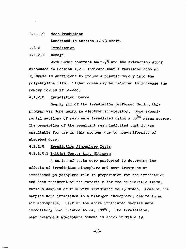
4.1.1.2 Mesh Production
Described In Section 1.2.3 above.
4.1.2 Irradiation
4.1.2.1 Dosage
Work under contract NASr-78 and the extraction study
discussed In Section 1.2.1 Indicate that a radiation dose of
15 Mrade is sufficient to induce a plastic memory Into the
polyethylene film. Higher doses may be required to increase the
memory forces if needed.
4.1.2.2 Irradiation Source
Nearly all of the irradiation performed during this
program was done using an electron accelerator. Some experl-
mental sections of mesh were irradiated using a Co 60 gamma source.
The properties of the resultant mesh indicated that It was
unsuitable for use in this program due to non-uniformity of
absorbed dose.
4.1.2.3 Irradiation Atmosphere Tests
4.1.2.3.1 Initial Tests: Air, Nitrogen
A series of tests were performed to determine the
effects of irradiation atmosphere and heat treatment on
Irradiated polyethylene film In preparation for the Irradiation
and heat treatment of the materials for the deliverable items.
Various samples of film were irradiated to 15 Mrads. Some of the
samples were irradiated in a nitrogen atmosphere, others In an
air atmosphere. Half of the above irradiated samples were
immediately heat treated to ca. 1OO'C. The irradiation,
heat treatment atmosphere scheme is shown in Table 19.
-68-

Table 19
Irradiation Heat Treatment Atmosphere Experimental Scheme (Air, Nitrogen) Irradiation of 1 Ml1 Sea Space
Polyethylene Film to 15 Mrads
Run. No.-- Irradiation Atmosphere Heat Treatment Atmosphere
; Nitrogen Nitrogen Air Nitrogen
2 Nitrogen No Heat Treatment Air No Heat Treatment
_-
Tensile tests were then performed about onceevery
three days for almost a month. The tests which were repeated
twice, A & B runs, (see Figures 17-20) in general show an ln-
crease In strength (reported as modulus of elasticity, E) with
time which appears to persist. It is believed that some of the
variations In the results are caused by the competing effects
of oxygen degradation and post-irradiation crosslinking. Both
effects are caused by residual post-irradiation trapped free
radicals caused by the entering electrons. It therefore appears
that the initial heat treatment given to some of the Samples
was not sufficient enough to decay the free radicals.
With the possibility In mind that the Initial heat
treatment was not sufficient to eliminate the free radicals, all
four of the samples were carefully heat treated above their
crystalline melting point on the 12th day (this means that two
of the samples were heat treated twice.) Tensile tests were
then performed on the samples to check for variations with time.
The results, shown in Figures 21-24 still in general appear
to rise somewhat, although the variation Is less than before the
second heat treatment.
-6g-

4.1.2.3.2 Tests: Oxygen, Nitrogen, Air
To further evaluate the effects of atmosphere
(especially the effect of oxygen) on polyethylene film during
Irradiation, samples of film were irradiated and heat treated
In an oxygen atmosphere In combination with the other gases used
In the first part of the
were conducted according
Tensile tests were again
days for three weeks.
experiment (nitrogen and air). The tests
to the scheme outlined In Table 20.
conducted approximately every three
Table 20
Irradiation Heat Treatment Atmosphere Experimental Scheme (Ox3wn, Nitrogen, Air) Irradiation of 1 Mil Sea Space
Polyethylene Film to 15 Mrgis
Run No. Irradiation Atmosphere Heat Treatment
; Oxygen Oxygen Oxygen Nitrogen
2 Oxygen None Nitrogen Oxygen
5 Air Air
The results of this set of tests are summarized In
Figures 25 - 29. In general, there is a fairly sharp Increase
In strength for all of the runs a few days after Irradiation which
then levels off approximately in 18 days. The samples
show larger increases in strength in the go0 direction than
In the Oo direction. In all cases there appears to be no
degradation. In fact there is a net Increase In strength for
all tests. Also, the fact that there was a net Increase (although
small) in strength with samples Irradiated in oxygen and
heat treated in oxygen, Indicates with some certainty that
the effect of oxygen is not critical in the Irradiation or
-7o-

heat treatment of this polyethylene film under the conditions
used In our evaluation. These results lead to the conclusion
that Irradiation and heat treatment In air will present no
problem with regard to oxygen degradation. In fact, run No. 5,
Figure 29 Irradiation and heat treatment in air, shows approxi-
mately 10 psi Increase at steady state over Its Initial
unlrradiated conditions. Additionally, samples originally
Irradiated for this program were tested after 31x months. These
samples showed no degradation.
4.1.2.3.3 Effect of Dose
For Informational purposes the Initial tests listed
In Table 19 were run at 30 Mrads to check the effect of
increasing the dose on the strength time curves of the film.
The results are given In Figures 30 - 33. The results In
general increase sharply upon irradiation and gradually decrease.
The decrease, although noticeable, does not indicate any
serious degradation.
-7l-

) -
I-
3
I-
Figure 17 STRENGTH-TIME CURVES FOR IRRADIATED(15 MRADS) 1 MIL SEA SPACE STANDARD DENSITY POLYETHYLENE FILN
E (psi x 103)
A 0' direction to extrusion 0 900 direction to extrusion
Irradiation: 15 Mr., Nitrogen Heat Treatment: Inert Atmosphere, 1OOOC.
darkened symbols Indicate second run
0 0 0
A A Q
I0 Q 8 2
A
A
0 O
A
0 A
0 0
0 A A
AA
I I I I I I I I I I I I I I I I I I I I I I I I 1
0 120 240 360 480 600 TIME IN HOURS

Figure 18 STRENGTH-TIME CURVES FOR IRRADIATED (15 MRADS) 1 MIL SEA SPACE STANDARD DENSITY POLYETHYLENE FILM
46 E -(psi x 103) A O" direct1 on to extrusion Irradiation: 15 Mr., Air
l 0 900 direction to extrusion Heat Treatment: Inert Atmosphere,
0 darkened symbols Indicate
0 1oooc.
second run
0 0 40- 0. 0
A A
- -13 w 3ol-
0 O0
A
A
I A 0 A
0 A Q
A A A 1 A
20' A
I I I I I I I I I I I I I I I I I I I I I I I I 10 4
0 120 240 TIME IN HOURS 360 480 600
A
I

46
Figure 19 STRENGTH-TIME CURVES FOR IRRADIATED (15 MRADS) 1 MIL SEA SPACE STANDARD DENSITY POLYETHYLENE FILM
E (psi x 103)
F
8 0' direction to extrusion Irradiation: 15 Mr., Nitrogen
900 direction to extrusion Heat Treatment: None darkened symbols Indicate second run
40 0
00 0
0
0
A 0
A A
0
A
A
A b - A 10
O0 0
AA A
A
A
0
0
A A
c
1c 1 II I I I I I I I I I I I I I I I I 1. 1 I I I I I I t
0 120 240 360 480 600 TIME IN HOURS

4t
4(
3( I 2 I
2(
E psi x 103) Figure 20 STRENGTH-TIME CURVES FOR IRRADIATED (15 MRADS) 1 MIL SEA SPACE
STANDARD DENSITY POLYETHYLENE FIIM
A 0' direction to extrusion 090" direction to extrusion
Irradiation: 15 Mr., Air Heat Treatment: None
darkened symbols Indicate second run
0 0
0 A
00 0 0 0
A 0 A
A 0 AA A A A
A
00 A
A
0 0
0 A
A
A 2
I I I I I I I I I I I I I I I I 1 I I I I I A I
120 240 360 480 V I
700 TIME IN HOURS

46
40
3c
J-l cn I
2c
E (psi x 103) b
Figure 21 STRENGTH-TIME CURVES FOR IRRADIATED 1 MIL SEA SPACE STANDARD DENSITY POLYETHYLENE FILM
Irradiation: 15 Mr., Nitrogen Heat Treatment: Inert Atmosphere,
/ - 1oooc. Reheat Treatment: 108oC.
Figure 22 STRENGTH-TIME CURVES FOR IRRADIATED 1 MIL SEA SPACE STANDARD DENSITY POLYETHYLENE FILM
Irradiation: 15 Mr., Nitrogen Heat Treatment: Inert Atmosphere,
Reheat Treatment?'%C .
) -
) - A O" direction to extrusion 0 goo direction to extrusion
A O" direction to extrusion 0 go0 direction to extrusion
I I I I I I I I I I I I 120 240 0 120 240 0
TIME IN HOURS AFTER REHEAT TREATMENT

4c
A .
v
Figure 23 STRENGTH-TIME CURVES FOR IRRADIATED (15 MRADS) 1 MIL SEA SPACE STANDARD DENSITY POLYETHYLENE FILM
8 O" direction to extrusion Irradiation: 15 Mr., Nitrogen
90° direction to extrusion Heat Treatment: None Reheat Treatment: 108OC.
I -
240 0 120 TIME IN HOURS AFTER REHEAT TREATMENT
I’ Figure 24 STRENGTH-TIME CURVES FOR IRRADIATED (15 MRADS) 1 MIL SEA SPACE STANDARD DENSITY POLYETHYLENE FILM
A 0' direction to extrusion Irradiation: 15 Mr., Air 090° direction to extrusion ~eea,5aF~r~~e,n,",~tr":"80c
.
I I I I I I I I I I I I I I I I I 0 120 240 360
I TIME IN HOURS AFTER REHEAT TREATMENT
-77-
I
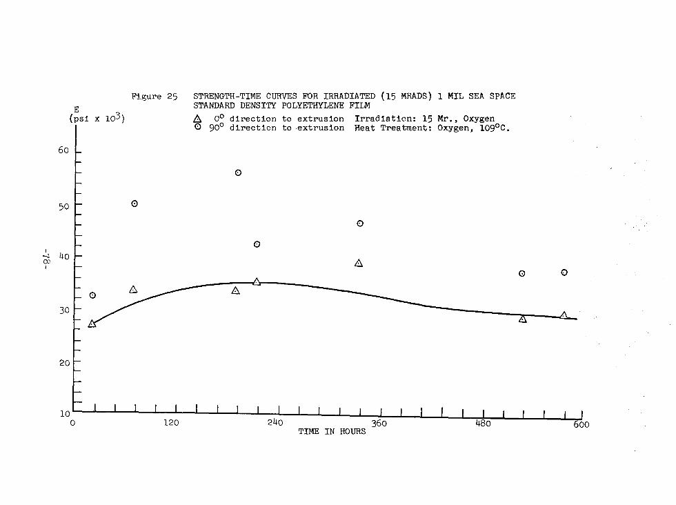
Figure 25 STRENGTH-TIME CURVES FOR IRRADIATED (15 MRADS) 1 MIL SEA SPACE E STANDARD DENSITY POLYETHYLENE FILM
(psi x 103) A O" direction to extrusion Irradiation: 15 Mr., Oxygen
I 0 90' direction to extrusion Heat Treatment: Oxygen, 109OC.
60 -
0
50 - 0
0
0 2 40 - 1 A
0 0 A . A
A
20 -
10 I I I I I I I I I I I I I I I I I I I I I I I
0 120 240 360 480 I j
600 TIME IN HOURS

40
30
I 2 I
20
E -(psi x 103)
A A
Figure 26 STRENGTH-TIME CURVES FOR IRRADIATED (15 MRADS) 1 MIL SEA SPACE STANDARDDENSITY pOLYJX'HYLENE FILM
A Oo direction to extrusion 0 go0 direction to extrusion
Irradiation: 15 Mr., Oxygen Heat Treatment: Nitrogen, 109W.
I I I I I I I I I lo0
I I I I I I I I I I I I I I I 120 240 360 480 600
TIME IN HOURS

Figure 27 STRENGTH-TIME CURVES FOR IRRADIATED (15 MRADS) 1 MIL SEA SPACE STANDARD DENSITY POLYETHYLENE FILM h O" direction to extrusion 0 900 direction to extrusion
Irradiation: 15 Mr., Oxygen Heat Treatment: None E
(psi x 103)
30 -
A
I E I
20 - A
-
0 120 240 360 480 TIME IN HOURS

46
1
20
12 I I I I I I I I I I I I I I I 1 I I I I I I I 0 120 240 360 480
1
TIME IN HOURS
E (psi x 103)
Figure 28 STRENGTH-TIME CURVES FOR IRRADIATED (15 MRADS) 1 MIL SEA SPACE STANDARD DENSITY POLYETHYLENE FILM
A O" direction to extrusion Irradiation: 15 Mr., Nitrogen 0 go0 direction to extrusion Heat Treatment: Oxygen, 1OgoC.
A

Figure 29 STRENGTH-TIME CURVES FOR IRRADIATED (15 MRADS) 1 MIL SEA SPACE STANDARD DENSITY POLYETHYLENE FILM
50- 7PSi x 103) A 0' direction to extrusion Irradiation: 15 Mr., Air 0 900 direction to extrusion Heat Treatment: Air, 1Og'C.
0
0
0
I
a A ' 30 -
A A n A A
A
20 - 20 -
I I I I I I I I I I I I I I I I I I I I I I I I I I I I I I I I I 1 I I I I I I I I I I I I 10 10 0 0 120 120 240 240 360 360 480 480 700 700
TIME IN HOURS TIME IN HOURS

50
40
I u” I
30
TIME IN HOURS
E (psi x 103)
0
A
A A
A
A
0
0
A
Figure 30 STRENGTH-TIME CURVES FOR IRRADIATED (30 MRADS) 1 MIL SEA SPACE STANDARD DENSITY POLYETHYLENE FIM
A O" direction to extrusion Irradiation: 30 Mr., 0 go0 direction to extrusion
Nitrogen Heat Treatment: Nitrogen, 109 C.
P
A

46
40
30 I z I
20
E psi x 103)
0 A
A
0 0
A A
0
A
A
Figure 31 STRENGTH-TIME CURVES FOR IRRADIATED (30 MRADS) 1 MIL SEA SPACE STANDARD DENSITY POLYETHYLENE FILM
8 0' direction to extrusion Irradiation: 30 Mr., Air 900 direction to extrusion Heat Treatment: Nitrogen, 109OC.
A
10. I I I I I I I I I I I I I I I I I I 0 I I I 120 I I 240 360 480
TIME IN HOURS

4(
2
E Figure 32 STRENGTH-TIME CURVES FOR IRRADIATED (30 MRADS) psl x 103) 1 MIL SEA SPACE STANDARD DENSITY POLYETHYLENE FIIM
A 0' direction to extrusion Irradiation: 30 Mr., Nitrogen 0900 direction to extrusion Heat Treatment: None
3-t
l(Y I I I I I I I I I I I I I I I I I I I I I I I I I
0 120 240 360 480 600 TIME IN HOURS
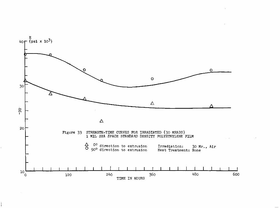
4o- TPSi x 103)
h
A A Figure 33 STRENGTH-TIME CURVES FOR IRRADIATED (30 MRADS)
1 MIL SEA SPACE STANDARD DENSITY POLYETHYLENE FILM
A 00 direction to extrusion o 90° direction to extrusion
Irradiation: 30 Mr., Air Heat Treatment: None
I I I I I I I I I I I I I I I I I I I I I I I 10
I J 0 120 240 360 480 600
TIME IN HOURS

4.1.2.3.4 Scatter in the Irradlatlon,Atmosphere Tests
The scatter observed in many of the irradiation
strength-time tests is in all probability due to the effects
of the effectiveness of dose variation with sample thickness.
For a given sample (or bundle of samples) of a material the
dose at the surface of the sample and to about 2mm. Inward is
not 100% effective since the high speed of the electrons do not
have sufficient time to Interact with the molecules. Data show-
ing how interaction efficiency varies with depth from the sur-
face is given In Figure 34,. which was taken from "Radiation
Chemistry of Polymeric Systems." l9
Figure 34: PERCENTAGE DEPTH DOSE IN WATER FOR HIGH ENERGY ELECTRONS
1 I 1
24 68 10 12 14
DEPTH IN WATER (mm)
-87-

It can be seen that for a 1.0 Mev accelerator the effective
dose may vary between 60 and 100% for samples 2 mm. thick or
less. It Is believed that since many of our samples were within
this depth range, they received non-uniform doses a8 given by
the above curve. This situation has been corrected for the
irradiation of the deliverable Items and samples for the testing
pra3ram. The applied dose was Increased to account for the lower
efficiency at and near the surface. The total dose the film
received on Its surface and throughout will be a constant
15 Mrads, since there will be very little variation In dose with
depth and only one thickness was used,
4.1.3 Heat Treatment
It has been found that irradiated polyethylene exhibits
a small amount (less than 5%) of shrinkage when heated near its
crystalline melting temperature. If the material Is heated to
just above Its crystalline melting temperature after it is cross-
linked the residual shrinkage would be removed for all future
steps. A temperature above the crystalline melt temperature (Tm)
has been chosen for the following reasons. The shrinkage at
elevated temperatures Is due to the recovery of residual strains
induced in the material during and after extrusion. The recovery
(analogous to creep recovery) proceeds much faster at elevated
temperatures. Above the crystalline melt temperature the
molecules are In nearly their most mobile state so they can
recover more rapidly into a new less aligned equilibrium state.
It should be pointed out that upon cooling the heat
treated material the main precaution that must be observed is
that the material should not be quenched. Quenching may cause
-00-

the polyethylene, which is In an amorphous state above its T,, to
remain amorphous. This Is undesirable since the properties
(In strength) of a quenched amorphous polymer are usually much
poorer than the crystalline polymer.
In light of this the rate of cooling of the cross-
linked polyethylene has always been slower than the usual rates
of film cooling as it emerges from an extruding process.
4.1.4 Perforations
The only specifications necessary for the perforation
of the film Is the perforation pattern. The perforation pattern
is determined from rigidity and resistance considerations which
have been described (Section 2.3) as well as the restriction that
the largest hole dimension can be no greater than 0.10 in. due
to radio-frequency reflectance considerations. This is so
providing the film.is perforated before It is metallized; since
the perforating operation causes cracks to propagate In the
metallic coating from the perforation, weakening the material
as can be seen in Figures 8 and 9.
4.1.5 __ Metallization
The metallization which is necessary for strength, and
radio-frequency reflectance should yield a metal coating with
a thickness of ca. 2200 i (and have a surface resistance of less
than 2 ohms/sq.). In the metallization of the test models these
specifications were set. Two metal coating processes were tried
during the course of this program. The processes tried were
electroless copper plating and vacuum deposition with aluminum.
It was found that the electroless copper process was successful
for the program while vacuum deposition processes are not
perfected sufficiently to be used to produce a workable metallized
-8g-

material suitable for passive communications satellites
using polyethylene as a base material.
4.1.5.1 Electroless Copper Plating
An electroless copper plating process whose solutions*
are manufactured by Enthone Inc. a division of ARSCO, In West
Haven, Conn. was applied to both mesh and film to determine
the operating variables and procedures necessary to plate copper
on polyethylene with good adhesion.
4.1.5.1.1 Recommended Plating Cycle
The following plating cycle was recommended by Enthone
after experimentation with the Rexwell polyethylene mesh.
Suggested Plating Cycle
Samples of the Rexwell mesh (7.5 in. x 1.0 in.) were
treated in accordance with the plating cycle suggested by Enthone
which is presented below.
1.
2.
3.
4.
5.
6.
7.
8.
Cleaning in Enplate PC-452, 8 oz./gal., 150°F., 2 mins.
Cold Water Rinse.
Neutralize in Enplate AD-480, 8 oz./gal., at room temperature, lo-20 seconds.
Cold Water Rinse.
Condition in Enplate Conditioner 472, full strength, at room temperature, 10 minutes.
Thorough Cold Water Rinse.
Sensitize in Enplate Sensitizer 432, diluted 1 part Concentration to 15 parts deionized water, at room temperature, 1 minute.
Cold Water Rinse. (NOTE: This rinse must be very thorough in order to avoid contamination of subsequent solutions.)
* Enthones Electroless plating solutions are commercially available ready formulated propriety solutions.
-SO-

9. Activate in Activator 440, diluted 1 part Concentration to 15 parts deionized water, at room temperature, 1 minute.
10. Thorough Cold Water Rinse. See note above.
11. Plating: Electroless Copper Plate in Enplate CU-400 made up 2 parts CU-bOOA, 5 parts CU-4OOB, and 9 parts deionized water, at room temperature, Time: variable.
12. Thorough Cold Water Rinse.
13. Dry.
Before proceeding further a brief discussion of the
purpose of each of the above plating steps will be listed.
Since each of the solutions are proprietary and the development
of the mechanism and theory of electroless plating is beyond the
scope of this contract, only a very approximate outline will
be given.
(1) Cleaning (Enplate PC 452) - Removed of greases and dirt from polyethylene with a detergent cleanser.
(2) Cold Water Rinse.
(3) Neutralize (Enplate AD-480) - To remove any residual alkaline deter ent of step (1) to protect the highly acidic bath 7 5).
(4) Cold Water Rinse.
(5) Condition (Enplate 472) - The conditioner contains chromate salts and sulfuric acid. It oxidizes and unsaturates the surface of the film rendering it more receptive to the tin salt adhesion in step (7).
(6) Thorough Cold Water Rinse. This rinse must be very thorough in order to avoid drag-in of conditioner to bath (7) which will contaminate It. The remaining cold water rinses should be addltion- ally thorough so the baths following others will not be contaminated.
(7) Sensitize (Sensitizer 432) - This step deposits or complexes Sn++ on the surface of the polyethylene.
-g1-

(8) Thorough cold water rinse.
(9) Activate (activator 440) -The deposition or complexing of Pladium is accomplished in this step.
(10) Thorough Cold Water Rinse.
(11) Plate (Cu 400 A and B) - In this step the actual electroless deposition of copper is accomplished At first copper oxide deposits upon the surface of the film which then rapidly changes to copper with increasing deposition.
(12) Cold water rinse and drying.
4.1.5.1.2 Plating Cycle for Mesh
The basic plating cycle and operating conditions
given above had to be modified in order to achieve a satisfact-
ory plate. The modifications are as follows:
1. In the conditioning step (5) in order to achieve
thorough oxidation, it was necessary to increase the operating
temperature to 30° - 40°C. range and increase the immersion
time to 25 minutes. The heating was accomplished.by use of a
chemically-pure lead sheathed immersion heater.
2. In the plating step (ll), moderate air dispersj.on
and operating temperatures in the range of 65' - 750F. were
necessary so as to deactivate the bath. This was required for
two reasons: to preserve the bath and to prevent the excess
formation of poorly conductive copper oxide in the plated copper.
It must also be pointed out that an excess of dissolved air
deactivates the solution so as no plating occurs.
The immersion time in the plating step was held
to 10 minutes, so as to give a nominal plating thickness of
10x10 -6 inch. This is in accordance with information received
from Enthone stating that the plating rate In a bath at the
-g2-

stated concentrations Is 1 x 10' 6 in./min.
3. Agitation of the mesh in the following baths
was necessary to insure proper liquid contact (and removal of
adhering gases) in the following steps:
Conditioner (5)
Sensitizer (7)
Activator (9)
Plating (11)
4. After each step very thorough (but gentle) spray
rinsing was applied to the treated mesh to prevent "drag in"
from one processing solution to the next. This was necessary
to preserve each bath as well as to insure proper contact of
solution with the mesh.
5. In order to protect the copper surface an anti-
oxidant treatment step (13) has been added to the plating cycle.
Treatment consisted of immersing the plated mesh in a solution
of 1 part Entek Cu55 and 99 parts deionized water for a minimum
time of 15 minutes. The mesh was then rinsed and dried rapidly,
4.1.5.1.3 Plating Cycle Film
The plating cycle for the film incorporates the
recommended plating cycle 4.1.5.1.1 and the modifications for
the mesh with one exception. In the conditioning step (5) the
temperature was raised to 40' - 50°C range and the immersion
time was increased to 1 hour.
4.1.5.2. Aluminum Deposition
The vapor deposition of aluminum was investigated as
a second means&' metallizlng the polyethylene film. The vapor
deposition processes was investigated as an alternative to
-93-
L. - -

electroless plating mainly because of its lower cost. It was
found that the vapor deposition of aluminum process could not
adequately be applied to polyethylene film.
The main problem In the deposition of aluminum on
polyethylene Is the fact that polyethylene has poor heat
stability resulting in a loss of dimensional stability
during the aluminum deposition application. The loss in
dimensional stability becomes greater as the thickness of the
aluminum coat applied gets greater (see Table 21 and Figure 35).
Although it is possible to deposit the required thickness of
aluminum to give a satisfactory surface conductivity the
resultant laminate material becomes badly distorted (wrinkled,
warped and curled). Even with a deposition thickness of only
500 P the loss in dimensional stability is still observed.
The above results indicate that the state of the art of aluminum
depositiqn on polyethylene is not sufficiently advanced to
warrant the application of aluminum in sufficient thickness on
polyethylene to obtain a laminate material that has dimensional
stability.
-g4-

Table 21
Properties of Aluminized Polyethylene Film, Aluminized by National Metallizing Div. of Standard Packaging Co., Trenton, N, J.
Film Type Aluminum Thickness Sample Size Resistance
(angstroms) in. x in.) (ohms/sq. ) Description
Run # 1 PE 12
Unirradiated 1500
Irradiated 1500
2 x 3.5 0.85
2x3 0.30
badly wrinkled
badly wrinkled and black
Irradiated, Heat Treated 1500 2 x 3.5 0.57 badly wrinkled
Unirradiated 2800 2 x 3.5 1.14 wrinkled, black I
Irradiated 2800 1.5 x 3 0.75 wrinkled
Irradiated, Heat Treated
Run # II
Unirradiated (PE 12)
Irradiated (PE 11)
Irradiated (PE 11)
2800 2 x 3.5 0.85
500 3x5 2.00
500 11.5 x 11.5 4.50
500 11 x g 5.00
wrinkled, slightly black
wrinkled
wrinkled
wrinkled

A B
Figure 35 ALUMINIZED IRRADIATED FILM
A - 500 "A
B- 1500 "A
c
c - 2800 w
-g6-
- I

4.1.6 Cutting
The cutting of the polyethylene copper laminate
presents no problems. The material was continuously slit
using ordinary film handling equipment for large size pieces.
For small patterns the film has been cut using a template.
Tolerances of tO.05" can be realized.
4.1.7 Ultrasonic Bondinq
The bonding of all sections of laminated material
was accomplished by ultrasonic bonding (ultrasonic welding)
techniques. In general, ultrasonic bonding is accomplished by
placing two samples of material, usually a plastic, to be
bonded under a bar and oscillating the bar at ultrasonic
frequency. The high frequency of oscillation induces motion
only at the surfaces of the material thereby inducing heat at
the surface permitting the two surfaces to mesh together. Since
very little motion is induced in the interior of the samples
there is no heat build-up there. In this way there is no
distortion or damage produced in the bonded film.
The ultrasonic bonder used in all experimental runs
as well as in producing the test models was an ultrasonic seal
"402" model bonder manufactured by Ultrasonic Seal; Division of
Kleer-Vu Industries, Inc., New York, N.Y. A schematic diagram
of the bonder is given in Figure 36.
-97-

Figure 36: SCHEMATIC DIAGRAM OF ULTRASONIC BONDER
ULTRASONIC GENERATOR
Series resonant filter Ground grid amplifier Push-pull power amplifier Polarizing DC supply with
blocking choke High voltage power supply
WEDDING HEAD SECTION
Fan cooled magneto- strictive transducer
) Servo motor drive
Welding Tool->
Sample
Cast irc<base (anvil)
4.1.7.1 Bonding of Mesh I
At first, continuous ultrasonic bonding methods were
attempted. The specimens to be bonded were passed between a
bar continuously operating at an ultrasonic frequency and an
anvil. The operation caused tearing and buckling of the mesh
at the bond and had to be discontinued.
It was then necessary to use an intermittent bar
welding operation. This operation consists of placing the
sample area to be bonded between the bar and the anvil, applying
pressure then oscillating the bar at ultrasonic frequency, and
then moving another area for the same treatment. This operation
resulted in a smooth and pressed bond.
Upon close examination of the bonded material, it
was observed that the bonded mesh easily peeled. This failure
to achieve a satisfactory bond was due to the interference
of the thin copper coating on the mesh surface. At first it
was believed that cleaning action caused by ultrasonic
frequency would sufficiently remove enough copper to permit a
-g8-

polyethylene bond. This was not the case. (This indicates
that the copper polyethylene bond is more than a mechanical
bond.) It was then necessary to remOve selected areas of
copper with nitric acid so samples could be bonded. With the
removal of copper from selected areas of the mesh, it was
found that a strong and true bond was achieved at those areas.
See Table 3.
With the establishment of the proper mesh surface
conditions and operating tool, the following operating
conditions were used to bond the mesh.
Operating Conditions:
1. Bar used: l/2 inch wide, 2-4 inches long, Monel metal, flat face.
2. Frequency: 20,000 cycles/second 3. Pressure: 4. Clearance:
70-80 psi 0.030-0.040 inch
5. Power: 400 Watts 6. Contact time: 1.5 second
t ultrasonic frequency applied)
7. Hold time: 0.5 second for cooling)
4.1.7.2 Bonding of Film
The conditions for the bonding of the crosslinked
film are essentially the same as for the mesh. The copper
must be removed from the areas to be bonded and the ultrasonic
welding bar is applied intermittently. Additionally, 30 ml1
Teflon coated fiberglas is needed below the sample while
5 ml1 polyvinyl chloride film was needed above for proper
heat dissipation and to achieve the best motion at the sample
surfaces to insure an adequate bond. The photograph in
Figure 37 shows the complete setup.
Operating Conditions:
Bar used: l/4 inch x 2-4 inch (inverse knurled
Frequency: 20,000 cycles/second Monel metal)
Pressure: 35 lbs.
-99-

clearance: 5 mils Power: 400 watts Contact Time: 1.5 seconds Hold Time: 1 second (for cooling)
The above conditions achieved a most satisfactory
bond between sheets of irradiated polyethylene. The strength
of the bond is nearly as strong as the polyethylene itself as
can be seen in the results of the testing program, Section
6.2.5.
.4.1.8 Packaging
As part of the testing program, experiments were run
to determine the ability of the copper laminated polyethylene
film to be packaged. The main factor examined in the tests
related to packaging is the ability of the laminate to be folded.
It was found that the laminate has excellent folding properties.
Samples were force folded under a variety of conditions (mainly
high and low temperatures - see Fold Resistance Tests,
Section 6.2.4, and electrical continuity was measured across
the fold. It was found (see Testing Program) that there
was only a negligible increase in resistance (4 ohms/sq.)
across the fold and that only a negligible amount of damage
to the copper coating occurred s_ee the (left) photomicrographs of
Figs. 68 and 69. In general a copper laminated polyethylene
film could be folded with a sharp crease with only negligible
damage occurring to the material. A complete folding and
packaging scheme will be given in Section 4.3.1.3 of the scale-up.
4.2 Test Model Fabrication Procedures
With the establishment of the operating variables
and procedures, test models were built.
-lOO-

Ultra-Sonic Welding Assembly
Left: Generator Right: Heat Mechanism
Detail of Head Assembly
Top to Bottom: welding head, polyvinylchloride film, perforated sample to be bonded, Teflon coated fiberglas and base.
Figure 37 ULTRA-SONIC WELDER
-lOl-

4.2.1 Mesh
The steps in the mesh fabrication program will only
be given for the spherical cap section. The other steps for
the fabrication of the cylinders are essentially the same. The
only exception is that the mesh used for the construction of
the cylinders was irradiated on a cylindrical form so as to
impart a memory into the material that will always give a
cylindrical shape upon restoration.
4.2.1.1 Cap Section Design
The design for the spherical cap section consists of
a number of gore segments cut so as to give a circular boundary
when bonded together and finally trimmed. A sketch of the
construction design can be seen in Figure 38.
The length and width of all gore subsegments (except
those on the circular boundary) are 49.00 and 14.50 inches,
respectively.
It has been shown in Appendix VI that the difference
between the maximum arc length contained in the cap section
surface and the corresponding diameter lying in the cap section
base is only 0.01 feet (Figure 39).
This result implies that any arc contained in the
cap section surface is approximately (i.e., within 0.08 inch)
equal in length to its projection in the circular base of the
cap section.
It has also been shown in Appendix VI that the width
of the center gore segment remains essentially constant. It
varies 0.023 in. from a maximum of 14.500 in. at the equator
to a minimum of 14.477 in. where the sides of the segment
intersect the circular boundary of the cap section.
-102-

----_
SECTION i
t GORE SECTION
Figure 38 LOCATION OF CAP SECTION WITHIN GORE SECTION OF CONSTRUCTED SPHERE
y24j14Y; b.24.00 ft.-!
Figure 39 CAP SECTION CROSS-SECTION
-103-

In view of the small curvature exhibited by the cap
section, the individual gore segments were cut in the form
of flat rectangles using a metal template as a guide.
Subsequently, one end of each gore segment was trimmed to
provide the required curved boundary.
In actuality, each segment was composed of a number
of 49-inch long subsegments. This was necessary since b-foot
lengths of 14.5-inch wide mesh constituted the most convenient
sizes for plating and irradiation.
4.2.1.2 Cap Section Fabrication
4.2.1.2.1 Irradiation - Mesh
The polyethylene mesh was machine irradiated to
15 Mrads with an electron accelerator at High Voltage Engineering,
Burlington, Mass. The mesh was irradiated continuously as a
flat section by passing it by the electron beam through use
of rollers.
4.2,1.2.2 Heat Treatment - Mesh
According to Section 4.1.3 the following operating
conditions were chosen:
Operating Temperature: 140-145'C. Atmosphere: Nitrogen Heating Time: 2 hrs.
In addition, at least one-half hour was allowed
for bringing the mesh up to 140°C. from room temperature.
The same minimum time interval was employed for
returning the mesh to room temperature after the 2-hour heat
treatment period has elapsed. This procedure insured against
thermal shock (quenching).
During the heat treating process, the mesh subsegments
lay on flat, horizontal aluminum trays to insure flatness.
-104-

4.2.1.2.3 Electroless Plating - Mesh
Successful electroless copper plating of the
deliverable items was accomplished., There was approximately a
20% rejection during the plating of the mesh due to incomplete
wetting of the mesh in the plating baths and improper rinsing,
which tended to prevent good treating liquid films from being
formed on the mesh surface. The rejection decreased as techniques
improved and strict adherence to the operating procedures were
observed.
4.2.1.2.4 Ultrasonic Bonding - Mesh
After cutting of the subsegments,fabrication was
completed by bonding them together ultrasonically using the
techniques and operating conditions given in section 4.1.7.1.
The "spot weld" bonding scheme is outlined in Figure 40.
4.2.2 Film
Flat sections and cylinders were constructed out of
metallized polyethylene film.
4.2.2.1 Irradiation - Film
4.2.2.1.1 Irradiation of Flat Film
In the irradiation of the flat material the film was
placed in a flat position on a steel conveyor passing the
electron beam. Two methods were tried before achieving successful
irradiation. At first the f.ilm was irradiated in 8 layer
thicknesses in an attempt to pass more material per given
irradiation time. Since electron irradiation causes a heat
build-up in any substance it strikes and the 8 thicknesses of
film were rolled on a film.winder after passing the beam, the
film had little chance to cool and some sticking occurred
rendering the film unacceptable for use. The next attempt,
-105-

equally unsuccessful, consisted of placing a single layer
of film on the conveyor and placing it across the beam,
and allowing it sufficient time to cool before rolling. In
this case the heat build-up in the steel conveyor was great
enough to make the film stick and fuse to it in spots. The
third approach which was successful consisted of lining the
conveyor with paper and passing the film on top of the
paper across the beam and then allowing the film and paper
sufficient time to cool before winding. Figure 41, a schematic
diagram demonstrates this method.
4.2.2.1.2 Irradiation of Cylinders
The film cylinders were irradiated in cylindrical
form, to obtain a permanent cylindrical shape, on a steel
core of 7.5 in. diameter. The core was lined with paper
to prevent the film from sticking on the metal. Additionally,
the core was rotated to give a uniform dose throughout the
surface of the cylinder. After each pass, sufficient time
(an hour or greater) was given for the cylinder to cool.
With the above precautions, no sticking or fusing occurred.
4.2.2.2 Heat Treatment - Film
The heat treatment of the crosslinked polyethylene
film on a continuous basis presented a number of problems some
of which have not been resolved as yet. It has been shown
(Section 4.1.3) that an effective heat treatment should be
done at a temperature above the T,. In the actual continuous
-106-

Plated Mesh l
L
Figure 40 SELJXTED AREAS OF REMOVED COPPER
Copper Removed
Film
'k,----- conveyor
Electron Beam
distance to cool before winding
Figure 41 SCHEMATIC DIAGRAM OF CONTINUOUS FILM IRRADIATION
-107-

heat treatment where the film is passed horizontally through
an annealing oven using film handling equipment (take up rolls
with rate and tensioning controls) it was very difficult to
control the tension of the film at its T,. This control problem
would result in a distorted unusable film. It was then necessary
to go to a lower temperature (93'C.) to accomplish the annealing
operation. This was necessary since it was beyond the scope
of work to run an experimental commercial scale continuous
heat treatment study. Recommendations are made on the solution
to this problem in Section 4.3.
4.2.2.3 Electroless Plating - of Film
Successful electroless copper plating of the
deliverable items constructed out of film was accomplished using
the operating variables already described. The film was plated
on 39 in. x 20 in. polyethylene frames to facilitate handling.
During the course of the plating operation quality control tests
enumerated in Appendix V were executed to insure proper bath
composition. Additionally, electrical resistance measurements
were run on the plated sheets of film to insure that the surface
conductivity of each piece was less than 2 ohms/square. The
surface conductivity in ohms/sq. of the plated film is reported
in Tables 4 and 5 of Appendix VII.
4.2.2.4 Ultrasonic Bonding - of Film
With the adherence of the operating variables set
forth in Section 4.1.5.1.3 successful ultrasonic bonding of the
irradiated.polyethylene film material was accomplished. Due
to the nearly complete lack of electrical continuity across
-108-

even a spot welded bond it was decided to remove all of the
copper at the bond. To determine if completely discontinuous
subsegments of the test models give different radio-frequency
reflectance characteristics than models whose subsegments have
electrical continuity, half of the test models were made to
have electrical continuity across subsegments by applying a
small conductive film across the bonds every 10 inches with a
conductive lacquer, whose properties are given in Table 22.
Table 22
Properties of Conductive Lacquer*
Continuous Phase (Solvent): Butyl Acetate
Disperse Phase: Powdered Silver
Conductive Film Thickness: Less than 1 mil
Surface Resistance: Less than 0.01 ohms/sq.
Manufactured by E.I. DuPont de Nemours & Co., Electrochemicals Department, Wilmington, Delaware.
-1og-

4.3 Scale Up
The fabrication of a full size 425 foot diameter
satellite would require the following steps in the production
scheme to be scaled up.
a) Heat Treatment
b) Electroless Plating
c) Packaging
Other phases of the construction have been done with equipment
which has the capacity for fabrication of the large sphere.
4.3.1 Stages Requiring Scale Up
4.3.1.1 Heat Treatment
As previously discussed the heat treatment of the
irradiated polyethylene film above its Tm on a continuous
basis resulted in distortion of the film due to difficulty
in the control of the tension on the film. An experimental
run would have to be undertaken before large quantities of the
film could be heat treated to determine the minimum tension
which would eliminate orientation of the film during heat
treatment.
A method of successfully controlling the tension
would be to pass the film through the annealing oven vertically,
letting the tension be that of the weight of the film. In this
set-up distortions due to over-tensioning or film sagging could
be eliminated. Alternately, the film could be laid on a
travelling bed so that no tension would be on the film during
the heating and cooling cycle.
-llO-.
I II.

4.3.1.2 Electroless Plating
The Enthone electroless plating process requires
a full scale up to continuous operation of all the treating
steps. To construct a 425 foot diameter satellite, approximately
700,000 ft. of 20 in. wide film is needed. This includes
scrap, excess, material for testing, etc. The approximate
rate of plating has then been set at 150 ft. per hour
of film plated with 15 x 10" in. of copper on both sides.
The operating variables in this scale up will be those given
in Section 4.1.5.1.3 above; only the residence time in the
actual plating bath will be changed to 15 minutes. In addition,
the quality control tests as given in Appendix V will still
apply to the large baths described below.
It is obvious that the continuous operation proposed
here would require design of special tanks for steps 5, 11,
and 13 which would‘permit the film to be festooned, thus,
decreasing the length of the tank while still maintaining the
required residence time.
4,3.1.2.1 Plating Baths
The size of the plating baths is based on the length
of the film required to be immersed in the bath in order to
obtain the correct residence time for a particular processing
speed. This would vary for-each step and for a continuous
process be governed by the slow step in the overall process.
The length of travel is given by
L=VT (23) where V = the rate of film production (150 ft./hr.)
T = the residence time
L = the length of travel
-lll-

Table 23 below gives a summary of the length of travel for
each bath.
Table 23
Summary of Immersed Lengths of Travel in all Plating Baths to obtain a Copper Thickness of 15 x 10m6 in, on
Polyethylene Film
Bath
1 Cleaner
3 Neutralizer
5 Conditioner
7 Sensitizer
T (Residence Time) L (Length of Travel) (min,) (ft*-Z- ..-.-
2 5.0
l/3 0.833
60 150
1 2.5
9 Activator 1 2.5
11 Plating bath 15 37.5
13 Antioxidant 15 37.5
With the length of travel for each bath established the tanks
for each step may be designed, In general, each bath will be
equipped with a recirculating pump, solution reservoirs, film
rolls and control equipment.
4.3.1.2.1.1 Cleaning Bath
The cleaning bath would be 5 feet long and 5 inches
in depth. It would be constructed out of 316 stainless steel.
A 55-gallon recirculating reservoir would be connected to the
tank. The cleaner detergent solution would flow countercurrent
to the direction of film motion. The following diagram
shows schematically the general set up for single pass
immersion.
-112-
- II

Motion of Solutio Temperature Film
Stain- less Steel Tank
ropylene Film Rolls
Stai
I I
y++n=== nless Steel Pump
/ In line full flow Filter (polypropylene)
Stainless &Steel
Gyp Reservoir 0
K LI Immersion Heater
Figure 42 SCHEMATIC OF SENSITIZER OR ACTIVATOR SYSTEMS
4.3.1.2.1.2 Neutralizing Bath
The neutralizing bath would have the same set up
as the cleaning step; only there would be no need for heating
or temperature control.
4.3.1.2.1.3 Conditioning Bath
The conditioning bath requires 150 feet of travel
to obtain a residence time of 1 hour. In this case it would
be necessary to have the film travel more than one pass
in the bath in order to decrease the length of the tank.
The set up for this step would appear as follows:
-113-

Figure 43 CONDITIONER BATH
Stain Steel TFE lined
Cross Current Solution Inlets Temperature (distributed) from Reservoir Control /
36"
Immersion Heater (Lead lined)
The tank and reservoir for this step would be 316 stainless
steel lined with tetrafluoroethylene (TFE) film. The tank
would be greater than 36" high and 15 feet long to accommodate
10 film passes. All auxiliary fixtures in the tank and reservoir
would be 'lined except the immersion heater which would be
lined with chemically pure lead. The reservoir would be
100 cubic feet in volume.
4.3.1.2.1.4 Sensitizer and Activator Stages -
The sensitizer and activator stages would be very
similar to the cleaning operation stage. The bath length
for these stages would be 2.5 ft. and no heating or temperature
controls would be needed.
4.3.1.2.1.5 Elcctroless Plating Bath
The plating bath needs 37.5 feet of travel at 150 ft.
per hour to obtain a residence time of 15 minutes. It would
therefore be necessary to have a multiple pass bath to lower
its length. A bath length of 5 feet would be satisfactory with -114-

a height of about 3 feet to accommodate between 7 and 8 passes.
As in the conditioner bath the solution flow would 'be cross-
current with a number of inlet entrances to insure satisfactory
liquid mixing. Since the plating bath life is dependent upon
temperature and air distribution, the plating bath would be water
jacketed for cooling and would have air dispersion. The bath
reservoir, piping and pump would be made out of 316 stainless
steel. The bath and reservoir would be polyethylene lined
so it may be cleaned with nitric acid to remove any copper that
may plate out. It would additionally be necessary to have a
replaceable full flow polypropylene filter (3-5 micron porosity)
in line to remove free particles of copper from the solution.
A schematic diagram of the plating system is shown in the
following Figures 44 and 45.
Figure 44 ELECTROLESS PLATING BATH
Temperature Cross Curre Control Inlets (dis
\ Cnrrm R‘3aa
nt Solution tributed)
Film
Nater cooled Jacket
thylene
I I 1 ‘11 I Stainless
Air / " Dispersion on Teflon coated
Film Rollers
-115-

Figure 45 - SCHEMATIC DIAGRAM OF PLATING BATH SYSTEM
plating solution disperses
1 I ’ , /I
I I/
I , I II
Air dispersion
30 ft.3 tank poly- ethylene coated 316
'nless steel water jacketed I
E
stirrer Pump
n line re-
200 gallon tank ater jacketed
1 J I 1
i!r dispersion
4.3.1.2.1.6 Antioxidant Step
This bath will have the same dimensions as the plat-
ing bath but with the same auxiliary equipment ss the clean-
ing step.
4.3.1.2.1.7 Rinsing Steps
The rinsing of the film as it goes from bath to,
bath would be accomplished by spraying with deionized water.
After the final rinsing step, the plated film would be air
dried.
4.3.1.3 Packaging
The ultrasonic bonding, folding and packaging -116-

will be done in essentially one step. The design requires
the ultrasonic bonding of 801 20 in. wide gore segments with
two 15.94 foot chord diameter polar caps. To reduce excessive
handling,the gore segments will be folded immediately after
they are ultrasonically bonded. The initial longitudinal
fold (pleat) will be in an "S" shaped configuration as shown
in the following diagram:
Blow-Up of Cross-Section of S-Pleated Sphere
Packaged Gore Segments
The 800 thicknesses of film will give a total thickness of
ca 0.80 in. The long pleated package of folded gore segments
will then be transversely folded ca. 134 times to obtain a
package approximately 20 in. wide, 60 in. long and
107.2 in. high.
-117-

5.0
5.1
MEMORY EFFECT
Experimental Tests
Three (3) sets of tests were conducted to characterize
and demonstrate the plastic memory effect. The first test
was a tensile test used to characterize the basic memory
forces. The second and third tests were used to demonstrate
the memory effect and to determine possible resistances to it.
These tests were deployment tests of cylinders and flat sections
in a l-g environment.
5.1.1 Memory Effect and Characterization of Memory Forces - Tensile Tests
It has been found from an investigation of the
literature concerning the theory of rubber elasticity that
memory forces (of a crosslinked material) can be characterized
above the T, by measurement of the modulus of elasticity (E) of
the film. It has been determined theoretically that the modulus
of elasticity can be given by the following equations:
E = 3 vkT (ref. 2) (1) where T = absolute temperature (above Tm)
K = Boltzmann constant lJ=NP(l- MC
;I n
where N = Avagadro's Number = density
L = molecular weight between crosslinks Mg = number average molecular weight
With the above equations as a guide it is now possible to
conclusively prove that very thin, crosslinked polyethylene
film exhibits a plastic memory even if it is not possible to
demonstrate this with a model test in a l-g field. In
unirradiated thermoplastics, i.e., linear polymers, once the Tm
-118-

is exceeded the plastic exhibits permanent flow properties
and the memory phenomenon is not observed as (Mc+ M, and v+ 0).
Irradiation of the thermoplastic, however, causes the development
of crosslinks in the thermoplastic, thereby, changing the
linear structure to the three-dimensional network. Radiation,
in effect, vulcanizes the plastic and makes it an elastomer.
The elastomeric properties, however, are not observed at
temperatures below the Tm because the crystalline forces are
much greater than the memory force. When the crystalline
forces are eliminated by exceeding the melting point, the
memory force is observed. In this way, the memory forces of
the crosslinked polyethylene film can be characterized by
measuring E above Tm. A tensile test performed above the T,
is conducted and the modulus of elasticity is measured. This
modulus is then a direct indication of the memory force exhibited
in the crosslinked polyethylene film. Additionally, after the
film is deformed, the tension is released and the film springs
back to its original dimensions thereby completing a memory
cycle. If the film were not crosslinked the modulus of elasticity
above the T, would be essentially zero, and the film would
exhibit permanent set characteristics after any deformation,
i.e., it would not spring back. These experimental results
based on the above theory have been demonstrated (see Table 24
and Figure 46 below). It can be seen from these results that
the crosslinked film does possess a modulus of elasticity
above the Tm and that additionally, the film can be deformed
and restored (cycled with minimal hysteresis loss) to its
original dimensions when it is above its Tm. Furthermore,
-11g-

the results qualitatively conform to the above equation. As
irradiation dose is increased the molecular weight between
crosslinks decreases thereby resulting in a stronger film.
Additionally, equation (1) predicts that the modulus should
increase with temperature. Although this is not observed,
the decrease with increasing temperature is small and can well
be due to thermal degradation.
Table 24
Characterization of Memory Forces - Modulus of 'Elasticity, E PE 12 Irradiated to 15 and 70 Mrads*
120°C. 14ooc. 15ooc. Dose E E E Mrads (psi x 103) (psi x 103) (psi x 103)
15 0.044 0.035 0.030
70 0.343 0.230 0.210
* Strain rate 2 in./min.
-120-

Figure 46: TYPICAL STRESS CURVE OF ELASTOMERIC POLYETHYLENE
I
STRETCH ; RELAXATION
SLOPE USED M EVALUATE MODULUS OF'ELASTICITY
i
i i
/i
\
I i i i i i i i i i i i i i i i
; I
i- STRETCH ELONGATION
f i i i i i i i i i i i i i i i i
i
RELAXATION ELONGATI ow-----; i
STRESS
STRAIN

5.1.2 Fold Resistance Tests
Samples of completely processed film were force
folded under a variety of conditions (see testing program
Section 6.2.4),-and subsequently placed in an oven at 12OOC.
(above the crystalline melting point). The samples were then
allowed to unfold. The degree of restoration of each sample
was then measured. It was found that the degree of restoration
ranged from O'(none) to 90' (50%).
5.1.3 Cylinder Deployment Tests
Cylinders constructed from material irradiated
on a cylindrical form(7.5 in. diameter),to Induce a cylindrical
memory, were folded along their longitudinal axis as shown in
Figure 47 to give a flat configuration. The folded cylinders
were then placed upright in an oven at 12OOC as shown in the
following diagram.
Fold
Flat Support Stand
Deployed *c---.-m-
I /--'---
Fold
(Cylinder is Original Configuration before Folding)
Figure 47: SCHEMATIC OF CYLINDER DEPLQYMENT TESTS
-122-

The cylinders were then allowed to unfold and restore.
At first, unplated cylinders of 1 foot length were tested. It
was found that considerable warping (due to gravity) and sticking
(blocking) occurred. See Figure 48. Therefore it was decided
to use 6 inch cylinders. A variety of cylinders were used to
determine different effects. Plated and unplated cylinders were
used to determine the effects of surface blocking on restoration.
Plated cylinders with and without copper at the fold were used
to determine the effect of the metal coating on restoration.
The results of the cylinder tests are summarized in Table 25
and Figures 48-50.
Table 25
Summary of Cylinder Restoration Tests (Base Material PE 12 irradiated on a cylinder)
Dimensions after Restoration*
Dimensions Major Minor Description Diameter Length Axis Axis of Cylinder _--- -- lin .I.- ._... .l.i_n,l --.--( in a 1 (in. 1 Comments
1 unplated 7.5 12 10.5 0.25 Considerable warping and blocking, little restoration
2 plated 7.5 6 7.75 5.00 Warping, no blocking, partial restoration
3 plated 7.5 6 8.25 (copper removed
2.75 Warping, no
from fold) blocking, partial restoration
4 unplated 7.5 6 8.75 0.38 Considerable warping and blocking, little restoration
5 unplated 7.5 6 8 5.25 Warping, no blocking, partial restoration
K---- ___ An approximate elliptical configuration was obtained after restoration.
-123

- -
Before Test Cylinder # 1 Height 12"
Diameter 7.5”
After Test
Before Test Cylinder # 4 Height 6”
Diameter 7.5”
After Test
Figure 48 PHOTOGRAPHIC RESULTS OF CYLINDRICAL MEMORY TESTS ON UNPLATED MATERIAL
-124-

Cylinder # 2 After Test
Height 6” Diameter 7.5”
Before Test After Test Cylinder # 5 Height 6”
Diameter 7.5”
Figure 49 PHOTOGRAPHIC RESULTS OF CYLINDRICAL MEMORY TESTS ON PLATED MATERIAL
-125-

Before Test
After Test Cylinder # 3 Height 6” 1" Width of Copper removed
Diameter 7.5” along folds
Figure 50 PHOTOGRAPHIC RESULTS OF CYLINDRICAL MEMORY TEST ON PLATED MATERIAL WITH COPPER REMOVED FROM FOLDS.
-126-

5.1.4 Conclusions on Memory Tests
Of the three (3) memory tests performed only the
tensile test method conclusively proved the existence of the mem-
ory and characterized and measured the fundamental memory forces.
The other two (2) tests, deployment tests, did not show complete
restoration. In the deployment tests It has been observed that
the following forces resist restoration: blocking,gravity,and air
currents. The blocking effect only predominates when the film is
not metallized. The effects of gravity and air currents were
observed on all of the tests and limited the effective demonstra-
tion of the memory of thin film materials. Although the effect
of air currents can be eliminated by running the deployment tests
in a vacuum chamber, the effect of gravity on the thin film mater-
ial cannot be eliminated in a l-g field. A number of follow on
tests are then suggested to conclusively demonstrate deployment
using the memory effect. With the development of a non-blocking
thermal coating,deployment tests should be run in a vacuum to elim-
inate the effects of air currents. The next test should be a O-g
deployment test (In space) on a small 3 dimensional model. The
O-g test would substantiate the feasibility of the plastic memory
effect in the deployment of thin film items. In fact,lt is strong-
ly believed by the authors,a test In a O-g environment presents
the only means of.demonstrating deployment of thin film materials
exhibiting the memory effect.
5.2 Deployment
A complete and definitive deployment studycannot
be made.at this stage since a thermal control heat transfer study
-127-

and O-g deployment tests on small test models is first needed.
With the assumption of the operability of the memory effect a
means of heating the surface of the sphere to above its Tm must
be achieved. Two methods of deployment are possible. In the
first method deployment would be initiated by preheating the
folded structure in its canister prior to erection. In the
second method expandable struts would rapidly expose most of the
sphere's surface to the sun. Heat would then conduct through
the rest of the unexposed area expanding the complete structures.
Another area needing study closely connected with
deployment is vacuum frictional effects (cold welding). Again,
a study of vacuum frictional effects should properly follow the
thermal control study, since the vacuum frictional effects of the
thermal control coating would be the surface requiring
investigation.
-128-

6.0 TESTING PROGRAM
The testing program on the perforated, plated
PE 12 film is essentially divided into two parts: (1) an initial
qualifications program checking the film with processing and (2)
a final qualifications program examining the finished film under
various environmental conditions. In the final qualifications
program both bonded and unbonded material were tested. The
complete testing program is outlined in the following table.
Table 26
Testing Program Scheme
Material T FR CFE FdR B R PM
Unprocessed Yes Yes
Irradiated Yes Yes
Irradiated-Heat treated Yes Yes
Irradiated-Heat treated- Plated Yes Yes Yes Yes Yes
Irradiated-Heat treated- Plated-Perforated* Yes Yes Yes Yes Yes Yes Yes
Irradiated-Heat treated- Plated-Perforated-Bonded* Yes Yes Yes Yes Yes Yes
- *Final qualifications tests run at a variety of test conditions:
vacuum, pressure, high temperature, low temperature, irradiation.
T = Tensile test
FR = Flexural rigidity test
CFE = Cyclic flexure endurance test
FdR = Fold resistance test
B = Blocking test
R = Electrical resistance measurement
PM = Photomicrograph
-12g-
II -

In general, It has been found that the film was
able to withstand nearly all of the above tests. The results of
the testing program are presented in the following sections.
6.1 Initial Qualifications Testing Program
The initial qualifications testing program was conducted
to test the material after each processing step. Flexural
rigidity (described in Appendix IV) and tensile tests (described
in Appendix I) were performed to follow the effects of processing.
Photomicrographs (250x) were taken of the surface of the plated
material, and, additionally resistance measurements were made
on all continuous plated material. The results of the initial
qualifications tests are given in Table 27 and Figs. 51 through 56.
The results show that the final material is ca. five times stiffer
than the original film. Figures 51 through 56 show that the
material must be stretched ca. 30% in order for it to begin to
lose electrical continuity. The photomicrographs in Fig. 56
show the surface condition of the metallized film (both perforated
and non-perforated) before and after a tensile test. It can be
seen that the copper coating is continuous and relatively smooth
before the tensile test. What appear to be scratches in the photo-
micrographs are actually extrusion lines. The photomicrograph of
the perforated sample before tensile testing also shows that the
ragged edges on the perforated boundary are coated copper. After
the tensile test the samples are shown to be cracked at the
metallic surface as would be expected.
6.2 Final Qualifications Testing Program
The final qualifications testing program was aimed
at investigating the effects of different environmental conditions
that would be encountered in space on the completely processed
PE 12, a minimum of 2 runs were used for all determined values. -130-

Table 27
Properties of Processed Sea Space Film (Thickness = 1 mil, Density = 0.931 gm./cc., 'I', = 117'C)
Direction Area Weight IDegrees) (lb/ft2 x 10-3)
F" (183) (3
* E" G"" (~~1x10³) (lb ln2/inx10-6)
Unprocessed Film
4; 90
Irradiated Film
E: ‘o.6ggto.oo5 2.28+0.15 31+4
4:65 0.578T0.010 2.0670.15
4.28+0.50
o.643zo.oog 1.76zO.34 29T3 37z4 ;*;7&.;: . . _
4;
90
Heat Treated Film
4.65 0.6g+o.o1 0.57To.005
2.44to.41 2g.1+1.7 l.gGo.18 29.59.6 4.g2+1.44 5.52T1.35
0.63Eo.12 1.7~0.24 37.53.8 7.6052.83
4; 90
Irradiated,Heat Treated, .Plated
0.74-i-0.06 2.8 +0.4 26.g+2.1 0.7270.08 2.9 TO.5 25.OT2.3 0.81~0.05 2.6 zo.1 3o.gzi.7
4; 5.31 0.6~00.03 0.73+0.06 0.58+0.07 0.5370.05 129 126 T6 +6 30.6 28.4 T4.82 +6.67
90 ;-;: . 0.7250.07 0.51~0.07 141 z7 29.2 z4.77

Table 27 (Continued)
Direction Area k?! eight (Degrees) (lb/ft x 10-3)
* Y **
ig, (PSAO3) (lb !n2/inx10m6)
Irradiated, Heat Treated, Plated, Perforated
4; 4.14 0.42+0.03 0.67+0.12 - 4.14 0.52TO.05 o.66To.og -
27.0+5.83 25.G4.27
90 4.14 0.4~0.04 0.65~0.08 - 25.1z3.64
* *Determined by Tensile Tests described in Appendix I, test run ten times. G y **
Determined by Flexural Rigidity Tests described in Appendix IV, test run ten times.

10.0
0.1
Figure 51 SURFACE RESISTANCE VS. STRAIN FOR COMPLETED MATERIAL, NON-PERmRATED (in O" and 45O Directions)
/--
Temperature:
measurement sistance
,<eviation in resistance / measurement
Radiation: ambient
Test Conditions: Temperature: ambient Pressure: ambient
10 20 30 40 50 60 CW) I I I I I
-133-
I

Figure 52 SURFACE RESISTANCE VS. STRAIN FOR COMPLETED MATERIAL, NON-PERFORATED (in 900 Direction)
1000
100
- . ET
-2 V ET al
1c
1
. Pre-Test Conditions: Test Conditions: Temperature: ambient Temperature: ambient Pressure: ambient Pressure: ambient Radiation: ambient
deviation in resistance measurement
/ / I
20 30 4%)
40 50
-134-

Figure 53
10
SURFACE RESISTANCE VS. STRAIN FOR COMPLETED MATZRIAL (in OoDirection)
Pre-Test Conditions: Test Conditions: Temperature: ambient Temperature: ambient B Pressure: ambient Pressure: ambient Radiation: ambient
&;7 / /-
/’ /
/ 1’ ,’ / / ’ /
/
/- 0keviation in resistance measurement
10 20 30 40 50 4%)
-135-

Figure 54 SURFACE RESISTANCE VS. STRAIN FOR COMPLETED MATERIAL (in 450 Direction)
1000
100
- rG
s
-2 p:
10
1
Pre-Test Conditions: Test Conditions: Temperature: ambient Temperature: ambient Pressure: ambient Pressure: ambient Radiation: ambient
i
deviation in resistance measurement
I I I 1 J. 10 20 30 40 4%) 50
-136-

Figure 55 SURFACE RESISTANCE VS. STRAIN FOR COMPLETED MATERIAL (in go0 Direction)
1000
1
Pre-Test Conditions: Test Conditions: Temperature: ambient Temperature: ambient Pressure: ambient Pressure: ambient Radiation: ambient
10 20 30 40 50 4%)
-137-

Before Tensile Test Pre-Test Conditions: Ambient
After Tensile Test Test Conditions: Ambient
TENSILE TEST ON UNPERFORATED, PLATED MATERIAL
Before Tensile Test Pre-Test Conditions: Ambient
After Tensile Test Test Conditions: Ambient
TENSILE TEST ON PERFORATED, PLATED MATERIAL
Figure 56 PHOTOMICROGRA HS OF PLATED MATERIAL,PERFORATED AND UNPERFORATED 250x) P
-138-

The conditions applied are as follows: high (117oC.) and low
temperature (-70°C.), cycling between -196OC. and lOO'C.,
vacuum (1 microtorr) and radiation (85 Mrads).
6.2.1 Tensile Tests
The results of the tensile tests are presented in
Table 28. It can be seen that none of the conditions resulted
in any degradation of the material. Only the high temperature
condition resulted in a loss of strength. This loss is reversible
and expected since there is a loss in modulus above the Tm.
Additionally, resistance measurements were taken during the
tensile test; it is seen from Figures 56 through 66 that the
plated film must be strained to ca. 20% before a loss in continuity
results.
6.2.2 Flexural Rigidity Tests
The flexural rigidity tests were additionally performed
under a variety of pre-test and test conditions listed in Table 29.
The flexural rigidity tests were performed according to the ASTM
Standard D1388-55T summarized in Appendix IV. The results of the
flexural rigidity test on the completely processed PE 12 are
listed in Table 29. It is seen that only at the elevated
temperature is the rigidity significantly decreased.
6.2.3 Cyclic Flexure Endurance Test
In the cyclic flexure endurance test 1 in. x 5 in.
samples of completely processed PE 12 under various pre-test
conditions listed in Table 30 were flexed about a curved bar,
according to Figure 67 for 200 cycles. The surface resistance
of the copper coating was continuously monitored. It was found
that all 24 of the samples were able to be flexed for 50 cycles
with minimal increase in surface resistance; on the other hand,
22 out of the 24 samples tested maintained a surface resistance -139-

Table 28
Final Qualifications Test: Tensilesa
F Pre-Test Condition Test Condition y (lbs. x 10-2) ITi (
Temp. Press. Rad. Temp. Press. O" 45O go0 O0 45O go0
amb. b micro- amb. torrd
amb. amb. 45+5 57+3 55t1 0.74*0.07 0.64+0.13 0.6250.02
amb. amb. 85 Mr. amb. amb. 7lil 108t8 8024 1.88to.03 1.8320.68 2.15~0.20
amb. amb. 85 Mr. -7OOC. amb. 88% 10*2 83t13 1.60fo.05 1.14+-0.26 1.33to.13
amb. amb. 85 Mr. 117OC. amb. 6.1h.7 3.8h.6 4.oto.4 2.59i1.21 1.35f0.15 3.2Ofo.80
amb. micro- torrd
amb. -700C. amb. 225~15 25328 215+5 1.94JTo.02 1.7020.10 1.68fo.23
A gamb. micro- amb. 117OC. amb. 3.2h.6 4.g*o.4 1.610.6 12.4 28.7 1.83fo.58 2.03fo.58 I torrd
LN2G BW amb. amb. amb. amb. 55+4 5424 47% 0.76+0.11 0.67t0.04 0.60t0.01 5ox
aAll tensile tests in testing program performed at 0.2 in./min., as described in Appendix I
b amb. = ambient
'LN BW2 = cycled in liquid nitrogen and boiling water 50 times 50x
d = 48 hours

Figure 57 SURFACE RESISTANCE VS. STRAIN FOR COMPLETED MATERIAL (in O", 45O and 90' Directions)
1.0 I I
Pre-Test Conditions:
45O Temperature: amb. Pressure: mlcrotorr
48 hrs. Radiation: amb.
Test Conditions:
O0
Temperature: amb. Pressure: amb.
8 (Z)
-141,

10
10,
1.0
10
1
0
.
Figure 58 SURFACE RESISTANCE VS. STRAIN FOR COMPLETED MATERIAL
(In O" and 45' Directions)
-
O0
Pre-Test Conditions: Temperature: amb. Pressure: amb. Radlatlon: 85 MI-.
Test Conditions: Temperature: amb. Pressure: amb.
1 1 L t I 10 20 30 40 50
E (8)
-142-

Figure 59 SURFACE RESISTANCE VS. STRAIN FOR COMPLETED MATERIAL (In go0 Direction)
9o”
Pre-Test Conditions: Temperature: amb. Pressure: amb. Radiation: 85 Mr.
Test Conditions: Temperature: amb. Pressure: amb.
0.10 I I I I I 1 - 10 20 30 40 50 60
6 (Z)
-143-

Figure 60 SURFACE RESISTANCE VS. STRAIN FOR COMPLETED MATERIAL (00 Direction)
O0
Pre-Test Conditions: Temperature: amb. Pressure: amb. Radiation: 85 Mr.
Test Conditions: Temperature: -70% Pressure: amb.
-144-

Figure 61 SURFACE RESISTANCE VS. STRAIN FOR COM- PLETED MAT IAL (In 45Oand gO"Dlrectlons.)
Pre-Test Condltions: Temperature: amb. Pressure: amb. Radiation: 85 Mr.
Test Conditions: Temperature': -7oOc Pressure: amb.

Figure 62 SURFACE
1000-
loo-
RESISTANCE VS. STRAIN FOR COMPLETED MATERIAL (in O'Dlrectlon)
O0
Pre-Test Conditions: Temperature: amb. Pressure: amb. Radiation: 85 Mr.
Test Conditions: Temperature: +117OC. Pressure: amb.
1.0 I I I I I 10 20 3640 50
g (29
-146-

Figure 65 SURFACE RESISTANCE VS. STRAIN FOR COMPLETED MATERIAL(in O",45' and
~90°Directlons)
10
v
Pre-Test Conditions: Temperature: amb. Pressure: microtorr 48 hrs Radiation: amb.
Test Conditions: Temperature: +117.oc Pressure: amb. I
1.

Figure'66 8.0
10.0
2.0 CI i
-2 V CF
a!*
1.0
.
0.1
vs. STRAIN FOR COMPLETED and 900 Directions)
MATERIAL
Pre-Test Conditions: Temperature: LN Pressure: ami;:
BW, 50x
Radiation: amb
Test Conditions: Temperature: amb. Pressure: amb.
10 20 30 40 50 c:($) I I L L ~~~ 1
-150-

Table 29
Final Qualifications Test: Flexural Rigiditya
Pre-Test Condition Test Condition G (lb.in.=)/in. x 10 -6)
Temp. Press. Rad. Temp. Press. 0" 450 go0
amb. amb. amb.
amb. amb. amb.
amb.
amb.
amb. I
G ';'LN2 BW
50x
LN2 BW 50x
3 50x
micro- amb. t0rr.o
micro- amb. torrb
micr B- amb.
torr
micro- amb. torrb
micro- torrb
amb.
micro- torrb
amb.
-7O'C. amb.
117OC. amb.
amb. amb.
-7O'C. amb.
5g.g6’21.18
16.27f4.37
34.1426.51
42.46'25.24
117OC. amb. g.88f5.28
amb. amb. 17.93+1.03 2g.87+o.g6 41.47t8.15
-7O'C. amb. 31.d12.64 44.44T18.33 44.92’16.41
117oC. amb. 3.39t2.05 4.84k2.02 4.44fl.48
31.84f7.go 45.40'12.71
10.78+3.og 16.64t6.14
36.4&n 28.13?7.61
48.47220.35 61.45+-12 .g6
8.6322.38 g.85+5.o3
aFlexural Rigidity Tests performed in accordance with ASTM D 1388~55T as outlined in Appendix IV. b Vacuum applied for 48 hrs.

Table 30
Final Qualifications Test: Cyclic Flexure Endurance
Pre-Test Condition Test Condition R sq after 200 Cycles Temp. Press. Rad. Temp. Press. 0" 45” 9o” Comments
1 amb. amb. amb. amb. amb. 0.62io.26 0.65io.40 0.66+0.10
LN 2 BW2 amb. amb. amb. amb. 0.63ko.04 o.g2+o.o8 o . g6ko
50x
LN 3 BW2
909above micro- amb. amb. amb. ~83fo.,80 0.63+0 2.00
50x torra specifications at 50 cycles
‘4 G
amb. amb. amb. amb. amb. 0.82+0.06 o.65+o.19 0.72+0.30 unperforated N I
aVacuum applied for 48 hrs.

Figure 67 CYCLIC FLEXURE ENDURANCE SCHEMATIC DIAGRAM
Clamp
\ \
\ \ \ I I
Redistance /
/
Weight

of less than 2 ohms/sq. for 200 cycles of flexure. Additionally
the photomlcrographs of Figure 68 show that there is minimal
cracking of the copper coating in the region of flexure.
6.2.4 Fold Resistance Tests
The fold resistance tests were performed to
determine the effect of force folding on the completely processed
material and to demonstrate the memory effect. Samples
(1 in. x 1 in.) of film were folded under a force of 0.5 lb./in.
of length under the pre-test conditions listed in Table 31. The
samples were then placed in an oven at 117OC. and allowed to
restore. It was found that the samples were not able to
restore (see Table 31), on the other hand, electrical continuity
was maintained although it was above 2 ohms/sq. The photo-
micrographs of Figures 68 through 71 show the cracking which
occurred at the fold. A perpendicular triple fold test was
additionally performed on the completed material. A sample of
material was folded three times; one fold perpendicular to the
other. The sample was then placed under a force of 0.5 lb./inch
of length for 24 hours. It was then pulled apart under the
same force. The result is seen in Figure 72 where the sample is
magnified 1.9 times. It is seen that the sample tore at the
apex of the two folds.
-154-

Table 31
Final Qualifications Test: Fold Resistance
R Pre-Test Condition
sq after Test Test Condition
pemp. Press. Time Rad. Temp. Press. (i-l/sq.) Opened Set Angle
(lb./in.) o" 45O go0 o" 45O go0
amb.
Iw* BW 25x
117Oc.
amb.
0.5 24 hrs. amb. 117%. amb. 6.0
0.5 24 hrs. amb. 117%. amb. 4.4
0.5 30 min. amb. 117oc. amb. 6.0
0.5 24 hrs. amb. amb. 0.5 lb/in. 11.31
4.7
3.6
6.2
4.56
7.6 61.3
3.8 25.0
7.6 o
2.83 -
45.0 77.5
90.0 60.0
20.0 0
iJl WI* 1 IW = ice water
BW = boiling water 25x = cycled 25 times.

After Test on Unperforated Plated Material
After Test on Perforated Plated Material
Pre-Test and Test Conditions: Ambient
Figure 68 CYCLIC FLEXURAL ENDURANCE TEST (250~)
Before Test Pre-Test Conditions:
0.5 lb./in. for 24 hrs.
After Test Test Conditions: 117OC.
Figure 69 FOLD RESISTANCE TEST ON PERFORATED, PLATED MATERIAL (250x)
-156-

After Test
Figure 70 FOLD RESISTANCE TEST ON
Pre-Test Condition: 0.5 Immersed alternately in Test Condition: 117OC.
PERFORATED, PLATED MATERIAL (250x)
lb./in. for 24 hrs. boiling water & ice water
Before Test
Figure 71 FOLD RESISTANCE TEST ON PERFORATED, PLATED MATERIAL (250x)
Pre-Test Condition: 0.5 lb./in. for 30 min; 117OC. Test Condition: 117oC.
-157-

Before Test Pre-Test Conditions: 0.5 lb./in. for 24 hrs.
After Test Test Conditions: 0.5 lb./in.
Figure 72 FOLD RESISTANCE TEST ON PERFORATED PLATED MATERIAL (Perpendicular Triple Fold)
-158-

6.2.5 Final Qualifications Test - Bonded Material
Completed PE 12 material ultrasonically bonded
under the cond+tlons summarized in Section 4.1.7.2 was subjected
to most of tests under the variety,of pre-test and test
conditions. The results are listed In Tables 32, 33 and 34 and
Figures 73 and 74. Due to the fact that It was difficult to
maintain electrical continuity across a welded bond and the
near impossibility of creating an adequate bond on or through
the copper, the copper was completely removed from all weld
areas and hence, no resistance measurements were needed.
The results show that the ultrasonic bond is nearly as strong as
the unbonded film, It Is additionally interesting to note the
ultrasonic action on the copper plate. The photomicrograph
Figure 73, left, shows the copper coat near an ultrasonic
bond. ft can be seen that there is a large amount of cracking,
nearly as much as if a tensile were pulled on the sample.
6.2.6 Blocking Tests
A limited number of blocking tests were performed
on the completely processed polyethylene material as part of
the testing program. Two 4 in. x 3 in. samples were placed
together face to face between sheets of glass. A 6 lb. weight
was then placed upon the top sheet of the glass. The complete
setup was then placed in a vacuum chamber operating at 1 mlcrotorr
for 48 hours. The samples were then taken from the vacuum
chamber, removed from the glass and pulled apart. The difficulty
in pulling the samples apart Is then considered the degree of
blocking, The materials on which blocking tests were performed
are listed in Table 35 with the corresponding results. The
-159-

Table 32
Final Qualifications Test: Tensilesa (Bonded)
F c Pre-Test Condition Test Condition y (lbs.) y 0 Temp. Press. Rad. Temp. Press. 00 go0 O0 9o"
amb.
amb.
amb.
amb.
amb.
I
5 amb.
I amb.
LN2 BW 50x
amb. amb. amb. amb.
micro- amb. amb. amb. torrc
amb. 85 Mr. amb. amb.
amb. 85 Mr. -2OOC. amb.
amb. 85 Mr. 117OC. amb.
amb. amb. -7OOC. amb.
micro- .amb. 117OC. amb. to+
amb. amb. amb. amb.
0.41~0.01b 0.42fo. olb 0.85fo.11~
0.31~0.01 0.3820.02 0.6520.01
0.6g+o.o1 0.67to.04 2.43+0.03
0.95+0.05 0.7gfo.21 2,10+-O.@
o.o04g+-0.0001 0.0031f0.0010 7.55-h.65
1.38iO.33 1.8 to.3 4.0 20.9
0.0015f0.002 0.012+0.001 32.45215.25
0.46+0.04 0.46fo.06 0.23to.18
o.81~o.13b
0.70+-0.05
2.4720.12
1.58k.38
4.85io.85
2.5 20.9
18.4524.55
o.98fo.03
aAll tensile tests performed at 0.2 in./min., as described in Appendix I. b
The result of five tests. C Vacuum applied for 48 hours.

Table 33
Final Qualifications Test: Flexural Rigidity (Bcnded)a
Pre-Test Condition Test Condition G (lb.in.2/ in. x 10 -6)
Temp. Press. Rad. Temp. Press. 00 go0
amb.
amb.
amb.
amb.
amb.
I K 7
amb.
LN2 BW 50x
LN2 BW 50x
LN2 BW 50x
amb.
arrb.
amb.
micro- torrc
micro- torrc
micro- tdrrc
micro- torrc
micro- torrC
micro- torrC
amb.
amb.
amb.
amb.
amb.
amb.
amb.
amb.
amb.
amb.
-70%.
117Oc.
amb.
-7oOc.
1179.
amb.
-7ooc.
117oc.
amb.
amb.
amb.
amb.
amb.
amb.
amb.
amb.
amb.
17.0527.38~
38.2829.06
1.79+1.13
17.97Q.79
43.35z12.78
2.OlG.03
11.84i4.8
38.14'17.52
1.8120.78
23.11f4,06b
48.87'10.09
4.06io.65
23.04T6.01
63.06'14.61
2.6121.48
13.90+4.45
75.58'14.47
2.2A.00
a Bond running the length of sample. b The result of five tests.
'Vacuum appl-l.ed for 48 hours.

34 Table
Final Qualifications Test: Cyclic Flexure Endurance (Bonded)a
Pre-Test Condition --_- Temp. Press. Had.
amb. amb. amb.
LN BW2 amb. amb. 50x
Test Condition Result (at Completion of 200 Cycles). Temp. Press. 00
amb. amb. one failure at 115th cycle
amb. amb. All
LN2 BW 50x
micro- amb. torrb
amb. amb. All
I K agond perpendicular to length of sample. ro I bVacuum applied for 48 hours.

Before Test After
Pre-test and test conditions: Ambient
Figure 73 TENSILE TEST ON BONDED PERFORATED, PLATED MATERIAL
f?? ., ’
:,.‘,
‘.,
After Test Test Conditions: Ambient
Figure 74 CYCLIC FLEXURAL ENDURANCE ON BONDED, PERFORATED, PLATED MATERIAL
-163-

blocking occurred at the polyethylene bond. It Is apparent
from this test and the deployment tests on the unplated
cylinders that polyethylene can be caused to block while
the copper does not block.
-164-

35 Table
Blocking Tests
Pre-Test Condition: Temp. : amb. Press.: microtorr Time : 48 hrs. Bad. : amb.
Test Condition: Temp. : amb. Press.: 6 lbs.
Material Description Results Comments
1. PE 12 non-perforated, plated degree slight blocking
2. PE 12 perforated, plated degree slight blocking
3. PE 12 plated, bonded (bonds folded perpendicular to
slight damage at degree blocking intersection of
each other) bonds I K ul I

7.0 CONCLUSION AND RECOMMENDATIONS
St is concluded that the results obtained from this
investigation have yielded sufficient design information to
permit construction of a 425-foot diameter sphere weighing less
than 1000 pounds.
In addition, the memory phenomenon is now more fully
understood and much of the data and procedures developed during
the investigation can be used to construct other expandable
items besides thin film spheres. Most noteworthy in this area
is the work done on polyethylene mesh. The irradiated, plated
polyethylene mesh could well be used for other items, such as
lenticular components, waveguides, booms, etc. without the
critical regard for buckling pressure since the mesh material
is much thicker than the thin film used to design the large
sphere. Furthermore, the deployment of mesh items can be 20
demonstrated in a l-g field.
The specific conclusions which follow indicate those
areas completed and the specific accomplishments realized.
In addition, a listing of work still needed is given.
7.1 Material Properties Development Program and Buckling Pressure Evaluation A copper laminated polyethylene film has been developed
which is light in weight and can withstand five times solar
pressure when fabricated as a 425 foot diameter sphere. In the
course of the development of the polyethylene-copper laminate
it was shown that a general method of increasing the strength
to weight ratio of a film is by application of a thin coat
of metal to the base film. The metallized material has sufficient copper thickness for adequate radio-frequency characteristics. The results of the testing program additionally
show that thin film polyethylene-copper laminates can withstand
-166-

the conditions of a space environment and withstand normal
handling for packaging. The material successfully withstood
vacuum, radiation, low temperature and mechanical handling tests.
Laminate peeling, film degradation or weight loss did not occur.
7.2 Test Models and Production
The necessary procedures for the production of the
large size satellites were investigated during this program.
The following list shows what has been accomplished.
a) Establishment of operating variables and procedures necessary for the production of large deliverable items.
b) The actual production of deliverable items.
c) Design information necessary for scale-up.
d) Cesign information still needed for scale-up.
The state of the procedures for scale-up are listed
below:
1. Production of a plastic film of given gauge and
density. Scale-up here is not necessary; sufficient data has
been compiled for complete characterization of the film.
2. Irradiation of the extruded plastic film. Sufficient
investigation was accomplished in the area of film irradiation
to warrant direct scale-up. The effects of depth-dose relation-
ship, irradiation environment, uniformity and film handling
have been investigated.
3. Heat Treatment. It was not possible to heat treat
the irradiated polyethylene film on a continuous production
scale basis during the course of this contract. It was found
necessary from experimental tests to heat treat the film above
its crystalline melting point; but when it was tried on a
continuous basis difficulty was encountered in controlling
-167-

the tensioning of the film. It was, therefore, necessary to
heat treat the film below its crystalline melting point; fully
realizing the film would not completely maintain its dimensional
stability if it were heated above its crystalline melting point.
In light of this it is then necessary to conduct further heat
treating tests on a production scale using continuous equipment
to resolve this problem.
4. Electroless Plating. In order for the polyethylene
film to have sufficient strength and the necessary radio-
frequency characteristics the polyethylene film was metallized
with copper using the Enthone electroless plating process. It
was found that plating thicknesses between l-20 x 10 -6 inches
of copper could be readily applied. The testing program sbwed
that this copper coating had excellent adhesion under the
environmental conditions that would be encountered in space.
The operating conditions and procedures for the electroless
plating of polyethylene films to various metal thicknesses have
been accomplished and sufficient information has been established
to scale-up the metallization for continuous production.
5. Ultrasonic Bonding. The operating variables and
procedures for ultrasonic bonding have been adequately established
during the course of this contract. It was found that a strong
bond could be created by ultrasonic methods which would withstand
the environmental conditions of space.
Two problem areas still remain to be solved in
conjunction with the ultrasonic bonding of polyethylene.
-168A

1. Electrical continuity cannot be maintained across an ultrasonic bond without coating over the bond, with a conductive lacquer.*
2. The unplated ultrasonic bond (and any unplated polyethylene) has a tendency to block when packaged.
In light of these two problems it is necessary to insure that
the exposed polyethylene is coated with a non-blocking material,
This problem will be resolved, incidentally, with the development
of the thermal control coating which will consequently be
required to be non-blocking,
6. Packaging - In light of the testing program which
showed that the film can be force-folded with minimal damage
occurring to it, a packaging procedure has been established
which permits packaging the 425 ft. sphere into a package of
74.4 ft.3 The development of a canister which is part of the
packaging program has not been investigated, since it was not
included in the scope of the contract. With the development
of the canister the packaging procedure would be complete.
7.3 Memory Effect and Deployment
Although it was possible to characterize and prove
that a plastic memory exists in irradiated thin polyethylene
film it was not possible to conclusively demonstrate the
deployment of test models constructed out of thin film poly-
ethylene. It was found that gravity, air currents and blocking
resist restoration thereby hindering full deployment. In order
to conclusively demonstrate that the plastic memory effect
7 The effect (if any) on the radio-frequency reflectance character- istic of electrical continuity across gores on passive communications satellites is still open to question. In an attempt to answer this question half of the test models produced had their bonded sections coated with a silver lacquer to insure continuity across bonds. At the time of this writing, the radio-frequency reflectance has not as yet been conducted.
-169

works on thin irradiated polyethylene film it is suggested that
a number of follow-on tests be conducted. These tests should
be run after the thermal control coating is developed since
the thermal control coating would have to be non-blocking.
The next deployment test should be conducted in a vacuum chamber
thereby eliminating the effects of air current. The final
test should be a O-g deployment test (in space) of a small
three-dimensional model. The O-g test would eliminate the
effects of gravity which are believed to be the main resistance
to restoration of thin film materials. The O-g deployment
test would conclusively substantiate the feasibility of using
the plastic memory effect in the deployment of thin film materials,
7.4 Thermal Control Coatings
An area necessary for the completion of this program
which was not included in the scope of work is thermal control
coatings. The area of thermal control coating is both necessary
to initiate deployment and maintain the required equilibrium
temperature 'once the item is deployed.
The utilization of the memory phenomenon is wholly
dependent on the application of heat to the packaged article.
The heat input must raise the temperature of the structure
to be deployed above its T,. As noted previously, the restoration
forces can only operate once the crystalline restraining forces
are removed. Therefore, step one in any deployment scheme
requires heating the structure above its T,. Since the
predominant source of heat in space is via radiative absorption
it necessitates control of the surfaces u/e ratio.
Initially, the CL/E of the metallized coating must be
-170;

determined and the equilibrium temperature to be expected
must be calculated.* The surface of the metallized film must be
changed either via the use of selected thermal control
coatings or a change in the metallization procedure. In either
case, a final c/c must be obtained which permits a Teq>T,
for deployment. Additionally, the thermal control coating
must be non-blocking not to interfere with deployment.
Once the sphere is deployed then the following
procedure is necessary to increase the rigidity of the sphere.
The large structure would, undoubtedly, require
cooling the structure considerably below its T, to increase
its rigidity. To effect this would require the development
of a thermal control coating which would
a. have an c/e ratio sufficient to heat the
structure above its Tm,
b. subsequently boil off and expose a second surface
with an c/e ratio which would result in a final
equilibrium temperature sufficiently cool to
permit the rigidity to be adequate to withstand
solar buckling pressures.
An initial determination of U/E was conducted at NASA towards the end of the contract; the results are presented in Appendix VIII.
-171-

8.0 LIST OF SYMBOLS
A@,)
D
E
F(P)
F cr
%
FY
FC(P)
G
"cL( t)
EL 0
H(t)
MC
Mn Mr, Mrad
N
pS
The function lWFv a(F,)
Cap section diameter (24 ft.)
Modulus of elasticity of polyethylene film, psi
The function 2E n R2k+
10-2kp + 1 7 P 1
Criticai loading force,lbf
Void fraction,dimensionless
Yield Force, lbs.
The function 24 TI R2k%Pcr t
10-2kp + 1 -4P 1
Flexural Rigidity lb.in.2/in.
Experimental flexural rigidity of polyethylene film of various thickness laminated with a constant thickness of copper, lb.in.2/in.
Average flexural rigidity in O" direction, lb.in.2/in.
Average flexural rigidity in 90' direction, lb.in.2/in.
t The function - %L(t)
Molecular weight between crosslinks
Number average molecular weight
Megarad
Avagadros Number
Critical buckling pressure = 5 P, = 6.5 x 10-g psi
Reduced critical buckling pressure,dimensionless P = cr 2E k+(t)2
see Figure 10, Section 3.0.
R
Solar pressure 1.3 x 10-g psi
-172-

LIST OF SYMBOLS (Continued)
The latitudinal angle in spherical coordinates
Radius of sphere 212.5 ft.
Experimentally measured resistance,ohms/sq.
Average experimentally measured resistance,ohms/sq.
&
R
k a 4 T
Tm
u( PI
Q(F,)
WA a
b
df
di Q
k
1
1 f
li
nR r
t
t cu V
X Y Z I
Residence Time
Crystalline melting point
2Ek4 The function - R2 pcrr(p) 4
Flexural rigidity after perforation of 0.30 ml1 lami-nated. ffl_m - Flexural rigidity before perforation of 0.30 ml1 laminated film
Area weight,lb./ft.2
Perforator dimension
The width of a spherical gore, see Appendix VI
Final diameter
Initial diameter
gravitational acceleration
s(l-v2),di mensionlessrand the Boltzmann constant
Perforator dimension
Final length, length of overhang
Initial length
Number of rows of holes on perforator die
Radius of deformation (inch) see Figure 11, Section 3.0
Thickness of polyethylene film, mil, inches
Thickness of copper plate, inches
The number of polymer chains per unit volume, and Poisson's ratio
Perforator dimension -173-

a
e
=Y 0
A
P cu
oF a
a U
aY R
LIST OF SYMBOLS (Continued)
Absorptance
Strain (dimensionless, or percent) and emittance
Yield strain, dimensionless
The longitudinal angle in spherical coordinates
A geometrical parameter for a spherical surface r4 =-, dimensionless
t2R2
A loading parameter dimensionless = R F,r
E t3
A geometrical parameter for a spherical surface = 2~'3 r2 1
R-5
Density of copper, gm./cc.
Density of polyethylene film,gm./cc.
Stress, psi.
Ultimate stress, psi.
Yield Stress, psi.
Ohms.
-174-

9.0
1.
2.
3.
4.
5.
6.
7.
8.
9.
10.
11.
12.
13.
14.
15.
16. Ibid. ref. 14.
REFERENCES
Charlesby, A., "Atomic Radiation and Polymers," Pergamon Press, London (1960).
Bueche, F., "Physical Properties of Polymers," Chapter III; John Wiley & Sons, New York, N.Y. (1962).
Flory, P.J., "Principles of Polymer Chemistry," Chapter IV, Cornell University Press, Ithaca, N.Y. (1953). -. Report NASA CR-274, "Ultra-thin Gauge Polymeric Films for Space Applications," Sea Space Systems, Inc., Torrance, Calif.
Report RAI-3333-1, "Upgrading of By-Product Polypropylene by Radiation Techniques," Final Summary Report, Radiation Applications, Inc., Long Island City, N.Y., March 15, 1965.
Pezdirtz, G.F., H. Price, "Mechanical Properties of Echo II Laminate," Aug. 1964.
NASA Technical Note TN D-2367,
Price, H.L., "Techniques for the Measurement of the Flexural Rigidity of Thin Films and Laminates," NASA Technical Note TN D-3270, April 1966.
Siebert, Leo, "How to Specify Perforated Metals," Machine Design, Vol. 38, No. 7, pp. 152-158, March 17, 1966.
Final Report, NAS5-1190, p. 4.1.
Rourk, Raymond 3rd Ed., p. 316.
J., "Formulas for Stress and Strain,"
Timoshenko, S. and Gere, "Theory of Elastic Stability," 2nd Ed., PP. 512-519, Spherical Shells".
"Buckling of Uniformly Compressed
Ibid., p. 518.
Ibid. ref. 10, p. 303,
Reiss, E.L., "On the Non-Linear Buckling of Shallow Spherical Domes," Journal of Aeronautical Sciences, Vol. 23, #lo, pp. 973-975, October 1956.
Reiss, E.L., H.L. Greenburg, and H.B. Keller, "Non-Linear Deflections of Shallow Spherical Shells," Journal of Aeronautical Sciences, Vol. 24, #7, PP. 533-543, July 1957.
-175-
I

17. Carlson, R.L., R.L. Stendelbeck and N.J. Hoff, "An Experimental Study of the Buckling of Complete Spherical Shells,' NASA Contractor Report NASA CR-550, Aug. 1966.
18. Biezeno, C.B. and R. Grammel, 'Elastic Problems of Single Machine Elements," Engineering Dynamics, vol. II, pp. 484-496.
19. Chapiro, A., Systems,"
"Radiation Chemistry of Polymeric Interscience Publishers, N.Y., 1962, p. lg.
20. RAI 308, Final Report, NASr-78, "The Use of Radiation-Induced Plastic Memo? to Develop New Space Erectable Structures,' pp. 8-11, April 15, 1963.
-176-

APPENDIX I - TENSILE TESTS
All tensile tests were performed using a standard
table model Instron testerequipped with a Missimers constant tem-
perature chamber, Figure 2. All Tensile tests were run on 1 inch
wide sampleswith a 1 inch grip separation. The strain rates used
were 0.2 and 2 in/min for most of the tests. The jaws gripping the
sample were pneumatically operated and gave a uniform clamping
pressure of 30 psi. In order to measure the electrical surface
resistance the plated samples were placed in tensile jaws previously
coated with silver oxide. Leads from this surface were connected to
an Ohmmeter to give resistance measurements. The set up is given
in Figure 3 . In all of the tests very little slippage was observ-
ed. Typical stress-strain curves obtained on the biaxially oriented
film are shown in the Figure below.
FORCE
STRAIN STRAIN
Figure 1 REPRESEk~ATIVE STRESS-STRAIN CURVES
I-l

Figure 2 INSTRON TABLE MODEL TENSILE TESTER Left: Cross-head and jaw assembly enclosed in Missimers
Constant Temperature Oven Right: Recorder for measurement of stress strain relationship
Figure 3 PNEUMATIC JAW DETAIL Top: Upper Jaw with Silver Oxide Plates for Resistance
Tensile measurement Center: Tensile Sample Bottom: Lower Jaw
I-2

The initial linear slope of the stress-strain curves
were taken as the modulus of elasticity
where A is the cross-sectional area of the film .
*Y’ as shown on the diagram has been taken as the
yield force although the actual yield force may be somewhere above
this (somewhere between the point where the curve becomes non-linear
and where it levels off). The Fy chosen will give a conservative
result for design purposes.
I-3

APPENDIX II - CRYSTALLINE MELTING POINT (T,) OF PE 12
The crystalline melting point (T,) of the Sea Space
film was determined in the following three ways:
1. Heating while restrained.
2. Stress relaxation upon increased temperature.
3. Modulus of elasticity changes with temperature.
1. Heating While Restrained
This experiment consisted of restraining 1 ml1 film
with seven 1.8 cm. diameter circles punched in a face-centered
hexagonal array, in a steel ring Figures 1 and 2. The restrain-
ed sample was then heated slowly from room temperature. As the
temperature increased, the circles became elliptical in shape,
At 116~~. the elliptical holes became more elongated and began
to tear. This temperature, where large deformations begin to
occur, Is indicative of the T, (crystalline melting point).
2. Thermal Stress Relaxation
One inch wide samples of Sea Space film were elongated
at 75’C. to their yield points on an Instron tensile tester
operating at a strain rate of 2 inch/min. The straining was
then stopped and heating was begun. Tine force to keep the film
at Its constant elongation was then measured as temperature
increased. The resulting data points are shown plotted In
Figure 3. It can be seen that the force begins to drop to zero
at 115OC. This temperature (115'C) Is indicative of the crys-
talline melting point temperature.
3. Modulus of Elasticity Changes With Temperature
The modulus of elasticity, E, of the film was
II-1

Figure 1 PERFORATED 0.15 MIL SEA SPACE FILM BEFORE ANNEALING
Figure 2 PERFORATED 0.15 MIL SEA SPACE FILM AFTER ANNEALING
II-2

250 r Figure 3: THERMAL STRESS RELAXATION TO DETEXMINE
CRYSTALLINE MELTING POIXT OF PE 12
Different symbols indicate different sample runs. Number of' runs: 5
4
3
2 1 i
TEMPERATURE (OC.)
11-3

determined from standard tensile tests at temperatures from
28Oc. to 1160~. The results are plotted in Figure 4. The
temperature where E approaches zero is considered the crystalline
melting point, since this is the temperature where the material
loses its solid properties and begins to behave as a fluid.
II-4

pg.4 x 103 at 28OC.
Figure 4: MODULUS OF ELASTICITY CHANGES WITH TEMPERATURE TO DETERMINE CRYSTALLINE MELTING POINT OF
10 -
9’
8-
6-
5-
4-
l-
20 30 40 50 60 70 80 go loo 110 120 130 TEMPERATURE (OC.)
11-5

APPENDIX III - DENSITY GRADIENT COLUMN
The density of PE 12 and the samples in the
extraction study were determined using a density gradient column
consisting of isopropanol and water operated at 23.3oC. The
column, whose dimensions are given in Figure 1, is recommended
in an article by G. Oster and M. Yamamoto. 1 Further procedures
for constructing, maintaining and operating the density gradient
column have been drawn from the ASTM-Standards, "Density of
Plastics by the Density Gradient Technique, 2 and the article
"Setting up a Density Gradient Laboratory".3 The density
gradient prepared is shown in Figure 2. It is capable of
measuring densities between 0.790 gm./cc. and 1.00 gm./cc.
at 23.3OC.
III-1

l.OOG
o .g8(
o.g6c
0.94(
- 0.92(
d \
i oegoc - 0.88c Pi :: z-4 0.86( E!
0.84(
0.82(
Figure 1: DENSITY GRADIENT APPARATUS
DENSITY GRADIENT TUBE
EYMM COVER \
.-FROM PUMP
,I.- it'0 REFRIGERATION
I WATER
I FOAM INSULATION (2" THICK)
BATTERY JAR COOLING COILS
1’
1’
1’
I-
>-
I’
I-
I-
I I I I I I I I I I I
o 3 6 9 12 LENk?H (t:.)
21 24 27 30 33
III-2

APPENDIX III - References
1. Oster, Gerald, M. Yamamoto, "Density Gradient Techniques ' Chemical Review, Vol. 63, #3, pp. 257-266, June 1963.
2.
3.
ASTM D 1505-63T, ASTM Standards Plastics-Methods of Testing, Part 27, June 1965, pp. 500-506.
Wiley, Richard, E., Laboratory,"
"Setting up a Density Gradient Plastics Technology, March 1962.
111-3
-

.
APPENDIX IV - FLEXURAL RIGIDITY TEST
The Flexural Rigidities of all samples measured in
this program have been measured by the ASTM D 1388-55T Beam
Cantilever Test described as follows:
A 1 inch wide sample is placed on a flat surface
and moved out over its edge until the leading edge of the
sample falls to an angle of 44.5O with the plane it is
slid off. See diagram below: I
i level
Bar movi- m 1
lf +I
I I
Sample
The length of overhang lf is then read. The test
is done, both in the 0 and 90 degree directions, and for each
direction it is done four times; on top foward, top back,
bottom forward,and bottom back. The flexural rigidity is
then measured as follows for each measurement
G = WA (2)3 (1)
An average flexural rigidity is then computed for
IV-1

each direction (i.e., EO, GgO) and the true flexural rigidity
is then given as:
(2)
In running the tests the following precautions were
observed:
1. All samples were slid over the edge at a steady, uniform rate.
2. Air currents were kept to a minimum.
3. All samples were brought to ground potential during each test with Static Master 3T125 B source antistatic brushes to eliminate electrostatic forces.
Iv-2

APPENDIX V - ANALYTICAL PROCEDURES FOR PLATING BATHS IN ENTHONE PLATING CYCLE
Plating Bath 5: Analysis for Enplate Conditioner z~--- --
Equipment Required:
1 - 10 ml. graduate
1 - 250 ml. graduate
l- 1.4ooto 1.620 (Specific Gravity) hydrometer
l- 2 ml. pipette
2 - 250 ml. stoppered Erlenmeyer flasks
1 - 59 ml. burette
Solutions Required:
50% HCl (6~)
20% KI (Wt.)
1% Starch solution (Wt.)
O.lN ka2S203
Procedure:
1.
2.
3.
4.
5.
6.
7.
Cool the sample to 75OF.
Measure the Specific Gravity of the sample. The Specific Gravity should be 1.590-1.608; if it is lower the solution should be heated and the excess water driven off.
Pipette a 2 ml. and dilute with
Add 10 ml. of a
Add 2 ml. of 6N
sample into a 250 ml. flask 100 ml. of deionized water.
20% KI solution.
HCl.
Stopper the flasks immediately and store in a dark place for 5-10 minutes.
Titrate the sample with O.lN Na2S203 to a straw color; then add 2 ml. of starch solution and titrate to a clear end point (greenish blue).
V-l

Calculation:
ml O.lN.Na2S203 x 100 = 5 activity of 30
Conditioner 472.
For each 10% low add 3/b oz./gal. of Enplate Conditioner 470
Additive.
Plating Sath 7 -
Analysis of Sensitizer 432 Working Solution
Apparatus Needed:
3 ml. pipette
25 ml. pipette
250 ml. Erlenmeyer Flask
25 ml. graduated cylinder
5 ml. graduated cylinder
Eye dropper
Hot plate
50 ml. burette
Reagents Needed:
EDTA Solution (EDTA Disodium Salt) 0.0575 M
Zinc Solution (Zinc Metal) 0.0575 M
A. R. Hydrochloric acid (HCl)
Ammonium Acetate (NH4C2H302) solution 30%
Hydrogen Peroxide (H202) 30%
Xylenol Orange Indicator Mix (0.1% by weight in sugar) (Fisher-Scientific Xylenol Orange Tetra- sodium Salt)
Procedure:
1. Pipette 3 ml. sample into 250 ml. Erlenmeyer Flask.
2. Add 5 ml. concentrated HCl.
3. Add 5 drops H202 (30%) of 2.5 ml. H202 (3%).
v-2
.

4. Heat on hot plate to boiling, remove and allow to cool.
5. Pipette 25 ml. Standard EDTA Into cooled solu- tion.
6. While swirling add 25 ml. NH@2H3O2 solution.
7. Add 1.5. g. indicator mix and dissolve.
8. Titrate with standard 0.0575 M zinc solution. Color changes from yellow to red.
Calculations:
0.55 x (25 -ml. zinc sol.) = $ (Vol.) of Enplate Sensitizer
432 in solution.
Replenishment:
Maintain the desired level of sensitizer 432 by
adding 38 ml. (1.3 fl. oz.) of concentrate per gallon of
solution for each 1% low.
Analytic:;1 Prccedure for Acidity of Sensitizer 432 Working Solution
Apparatus Needed:
2 ml. pipette
250 ml. Erlenmeyer Flask
Eye-dropper
50 ml. burette
Reagents Needed:
O.lN Sodium Hydroxide (NaOH) solution
Phenolphthalein Indicator
Procedure:
1. Pipette 2 ml. of sample into 250 ml.Erlenmeyer flask.
2. Dilute with approximately 100 ml. distilled water.
3. Add 3 drops of phenolphthalein indicator.
v-3

4. Titrate with O.lN NaOH. Color range is from clear to pink.
Calculations:
0.42 x mls titrated = $ (Vol.) Cont. HCl in solu- tion.
Replenishment:
Maintain the desired level of acidity adding:
For each 1% low add 75 ml. (2.2 fl.oz.) of
6N HCl (50$ by Vol.) for each gallon of solution.
If necessary, the acidity can be reduced adding
for each 1% high, 75 ml. (2.5 fl. oz.) of 6N NaOH (2lb/gal.)
for each gallon of solution.
A solution made up using 1 part Sensitizer 432
and 15 parts of water contains approximately an equivalent of
8s (by Vol.) of cont. HCl.
A solution made up using 1 part of Sensitizer 432
and 30 parts of water contains approximately an equivalent
of 4% (by Vol.) of cont. HCl.
A solution made up using 1 part of Sensitizer 432,
1 part of cont. HCl and 14 parts of water contains approxir,late-
ly an equivalent of 14% (by Vol.) of HCl.
Plating Bath 9
Analysis of Activator 440 Working Solution - Calorimetric Procedure
Apparatus Needed:
Set of clean dry test tubes (or Nessler tubes)
2 ml. pipette - 0.1 ml. graduations
10 ml. graduate
Procedure:
1. Set up standards ranging from 1% to 10% (Vol.)
v-4

by pepetting 0.1 ml. increments of Activator 440 concentrate into the tubes and adding water with the graduate to make 10 ml. of standard. (Th ese standards may be sealed and kept permanently.)
2.Place 10 ml. of filtered sample of Activator 440 working solution into the sample test tube,
3.0btain concentration versus transmittance curve using calorimeter at set wave length and temper- ature. (See Figure 1 on page v-6).
Replenishment:
Maintain the desired level of Activator 440 by
adding 38 ml. (1.3 fl.oz.) of concnetrate per gallon of
solution for each 1% low.
Analytical Procedure for Acidity of Activator 440 Eking Solution
Apparatus Needed:
20 ml. pipette
250 ml. Erlenmeyer flask
Eye dropper
Reagents Needed:
O.lN Sodium Hydroxide (NaOH) solution.
Phenolphthalein Indicator
50 ml. burette
Procedure:
1. Pipette 20 ml. of sample of Activator 440 into the Erlenmeyer flask.
2. Dilute with approximately 100 ml. distilled water.
3. Add 2 to 3 drops of phenolphthalein indicator.
4. Titrate with O.lN NaOH. Color change is from clear to pink.
Calculations:
0.042 x mls. titrated = $ of cont. HCl in solution.
v-5

Figure1 ACTIVATOR CONCENTRATION VS. TRANSMITTANCE at 535 x 10-g cm. and 24OC.
wavelength
l
84 86 88$ go 92 94 g6 98 NORMAL CONCENTRATION OF SOLUTION #9 -
88.3% TRANSMI'M'ANCE
v-6

-
Replenishment:
Maintain the desired level of acidity by adding:
For each 0.1s low, add 7.5 ml. (0.25 fl.os.) of
6N HCl (50% by Vol.) for each gallon of solution.
For each 0.1s high add 7.5 ml. (0.25 fl.oz.) of
6N NaOH (2 lb./gal.) for each gallon of solution.
A solution made
and 15 parts water contains
cont. HCl.
up using 1 part of activator
approximately 0.5% (by Vol.)
A solution made up using 1 part of Activator and
30 parts water contains approximately 0.25% (by Vol.) cont.
HCl.
NOTE: The concentration of acid in Activator 440 working solution is always under 1% (by Vol.).
Plating Bath 11
Analysis for Cu-4OoA -Operating Solution - Apparatus Needed:
50 ml. pipette
50 ml. burette
500 ml. Erlenmeyer flask
25 ml. graduated cylinder
Reagents Needed:
Glacial Acetic Acid
Potassiumiodide (KI) reagent.grade
Starch solution (1% soluble starch solution)
O.lN Sodium thiosulfate (Na2S203)
Procedure:
1. Pipette 50 ml. sample into 500 ml. Erlenmeyer flask.

2. Add 100 ml, distilled water.
3. Add 15 ml. glacial acetic acid (Color should change to light blue-green).
4. Add 15 g. KI (about 1 teaspoon), swirl until completely dissolved. (Color changes from light blue-green to dark brown).
NOTE: It is important to add KI as solid, not as liquid concentrate.
5. Titrate with O.lN Na2S203 until color changes from dark brown to light.brown or yellow.
6. Add 5 ml. starch indicator solution. (Color will change to dark purple or black).
7. Continue titrating with O.lN Na2S203 until color changes to white and remains clear for 1 minute.
NOTE: With some starch solutions the white may be tinged with a faint pink color which cannot be made to disappear.
8. Record ml. of O.lN Na2S203 used.
Calculations:
(0.883)(ml. O.lN Na2S203 used) = $ (by Vol.)CU-400$ present.
Replenishment:
Maintain at desired level of CU-4OOA by adding
38 ml. (1.3 fl. oz.) of CU-4OOA per gallon of solution for
each 1% low. CU-4OOB is maintained by adding an equal volume
of CU-4OOB for each volume of CU-4OOA replenished.
Free Alkalinity Control
The free alkalinity of a Z-5-9 bath should be con-
trolled by the following titration. This teat should only be
run after proper additions of both CU-LCOOA and B have been
made.
Apparatus Needed.
50 ml. pipette
250 ml. Erlenmeyer flask
v-8

50 ml burette
Eye dropper
Reagents Needed:
1N sulfuric acid (H2SO4) solution.
Phenolphthaiein indicator.
Procedure:
1. Pipette 50 ml. sample of CU-400 into a 250 ml. flask.
2. Add 50 ml. deionized water.
3. Add 3-4 drops of phenolphthalein indicator.
4. Titrate with 1N H2SO4 until all red color disappears. (Clear blue).
Calculations:
For a bath made-up using 2 parts A, 5 parts B,
9 parts water.
(221-13 x ml. of 1N H2SO4 used ) = ml. of a 2 lb./gal. (6N)
solution of NaOH needed per gallon of made-up CU-j+OO bath.
(30 ml. = approximately 1 fl. oz.).
v-9

APPENDIX VI - CAP SECTION DESIGN CALCULATIONS
The cap section considered has a radius of curvature
of R = 212.5 ft. and diameter D = 24 ft.
Maximum Arc Length
From Figurelbelow it can be seen that l/2 the max-
imum central angle (Qmax) is equal to:
Q max = sin -1 D = sin -1 12.00 m 212.50
= 3.237’
The maximum arc length is then equal to:
2(212.50 ft.) (3.237') (0.017453 rad - 24.01 ft. a+$-
arc
Figure 1: SIDE VIEW OF CAP SECTION
VI-1

Variations In Gore Width
The maximum variation in the gore width (b) of a
gore in the cap section is dependent on the angle Q (see Figure
2 ) measured from the plane defining the equator of the 212.5
radius sphere. Its dependence can be found as follows:
The length of an arc length b within a gore seg-
ment is equal to
b=Rl8 (2)
with 8 = 5%&-E)
From right triangle OAC
R1 = R cos Q
with R = 212.5
Combining equations 2 and 3: 14.5 b = T cos Q
(3)
A tabulation of the half gore width (-$b) versus the
angle Q from Q-0 at the equator to Q = Qmax at the upper
boundary is presented in Table 1 . It can be seen from the
table that the difference between the maximum gore width at
the equator to the minimum gore width near the upper boundary
is 0.002 ft., so for all practical purposes the lengths of all
the gores can be considered parallel within the cap section.
It is for this reason that the flat sections have been used in
the construction of the cap section.
VI-2

BOUNDARY OF CAP SECTION
Figure 2 ARC LENGTH 'vJTTHIN CAP SECTION
VI-3
CENTRAL GORE "T-al----- - ~ P SECTION

Table 1
Variation of Gore Width with Angle Q in Center of Cap Section
3 Gore Width
(h 0.60416 cos Q
(ft.)
0.108
1.89 2.00
x: 2160 2.80 2.90 2.95
3.29 3.30 3.304
0.60416 0.60416 0.60415 0.60413 0.60410
xz:E; 0:60403 0.60398 o .6o392 0.60383
E%:;: 0:60363 0.60354 0.60344 g A;;;;
0:60333
: 66757 1:48350 2.22525 2.96700
2%:~~ 4:45051 5.19226
9.64278 lo.384 2
2 10.755 0 11.94084 11.12628 11.31177 11.49715
it l Ezg 11:94220
0.60320 12.0100 0.60319 0.60318
12.05347 12.12764
0.603163 12.20182 0.603157 12.23890 0.6031546 12.25374
VI-4

APPENDIX VII - RESISTANCE DATA ON TEST MODELS
Table 1
Lengths for all Subsegments in Spherical Cap Section
Actual Maximum Length
Subsegment* (In.) Number
1-3-1 45.88 4
1-3-2 44.10 4
l-3-3 41.42 4
l-3-4 36.83 4
l-3-5 30.44 4
l-3-6 21.97 4
l-3-7 11.19 4
1-2-8 45.48 4
1-2-g 25.59 4
O-1-0 46.00 1
0-6-0 46.00 1
l-l-lo** 42.17 4
The remainder are all 49.00 68 complete rectangles
* Refer to Figure 1 ++
The width of these boundary pieces is 6.31 inch.
VII-1

Figure 1
DETAILED ARRANGEMENT OF CAP SECTION SUBSEGMENTS
VII-2

Table 2 Resistance of Various Subsegments in Spherical
Cap Section - Mesh Resistance Hesist'ance
Subsep;ment (ohms/square) Subsegment (ohms./square)
0:27 0.24 0.24 0.30
l-l-l 0.45 l-l-2 0.30 l-l-3 0.63 l-l-4 0,27 l-l-5 0.24 l-l-6 0.30 l-l-7 0.30 1-1-8 0.30 1-1-g 0.27 l-IL-10 0.30
1-2-1 l-2-2 l-2-3 l-2-4 ;-g-z - - l-2-7 l-2-8 1-2-g
0.30 0.24 0.30 0.2 0.39 0.48 0.30
0:8
1-3-1 0.43 l-3-2 0.30 l-3-3 0.33 l-3-4 0.41 l-3-5 0.24 l-3-6 0.5 l-3-7 0.60
2-l-l 2-l-2 2-l-3 2-l-4 g-i-2
f;j
2x9 2-l-10
0.18 0.30 0.24 0.30 0.30 0.24 0.46 0.18 0.60
2-2-l 0.20 2-2-2 0.21 2-2-3 0.24
2-2-4 2-2-5 2-2-6 2-2-7 2-2-8 2-2-g
2-3-l 2-3-2 2-3-3 2-3-4 2-3-5 2-3-6 2-3-7
3-l-l 3-l-2
3-2-l 3-2-2 3-2-3 3-2-4
E-65 3-217 3-2-8 3-2-9
3-3-l 3-3-2 3-3-3
3-3-7
4-l-l
z-t-; 4x4 z-t-2 - -
v11-3
0.18 0.24 0.30 0.30
0%
0:27 0.60 0.20 0.48 0.50 0.90
0.30 0.24 0.10 0.24 0.30 0.24 0.30 0.30 0.30
0.24 0,24
2;: O:18 0.30 0.24
0160
0.30 0.24
z 0:23 0.31 0.38
0.24 0.30 0.30 0.20 0.61 0.15

Table 2 (Continued)
Subsegment
4-l-7 4-l-8 4-.1-g 4-l-10
Resistance (ohms/square)
0.30
i% .
4-2-1
4-2-7
0.18 0.30 0.24 0.49
ix: 0142 0.24 0.23
4-3-l 0.60
z-; 41314
:*z 0162
4-3-5 0.20 4-3-6 0.30 4-3-7 0.38
Table 3
Resistance of Various Subsegments of Flat Sections - Mesh
Subsegment
1 5
4 2
7 8 9
E 12
Resistance (ohms/square)
0.51 1.70
E% 0:51
xi 1:98 1.53
VII-4

Table4
Resistance of Cylinders - Mesh
Cylinders
:
2
Resistance (ohms/square)
Table 5
Resistance of Various Flat Section Subsegments - Film
R e s i s t a n c e (Ohms) O0 9o" Overall
(length. =6rt)
(width 0 =4 rt) 1.
0. 0. 1. 1. 1.
6 63 2 0
44
0.9
;:: no con- no con- tinuity tinuity
p:i . ti
E 1. 1.
i 1.
1. 1. 1. 1. 1. 1. 1. 1. 1.
1. 1. 1. 1.
1. 1. 1. 2.
Flat Section No.
0 G
0 8
223
16
2 56
4
i3
.: 86 9 16 0
1.3- 1.06 1.1
0.8 0.7
g:i
1:4
4.8 4.8
5.5 3.8
VII-5

Table 5 (Continued)
Flat Section f 3es-ist ante I No. OU go0
4 ?‘$6 1:36 1.33 0.83 1.0 0.7 1.13 y.527
93
1:1 0183 1.0
Overall (length = 6 ft)
(width =4 rt)
no con- no con- tinuity tinuity
* Letters denote various subsegments
Table 6
Resistances of Cylinders - Film
1 ft. length x 7.5 in diameter
Cylinder Resistance of unbonded No. material for cylinders (Ohms)
u 90” 1 1.; 1.4 no continuity
5 1.8 1.0 Silver lacquer* 1.8
4 1.8 i:; Silver lacquer* no continuity
* Silver lacquer used. DuPont Silver prep. electronic grade 4817 solvent Butyl Acetate
~11-6

APPENDIX VIII - THERMAL CONTROL PROPERTIES OF METALLIZED FILM
The absorptance over emittance u/e of the metallized
film was determined at NASA GSFC, The absorptance measurements
were determined by use of a Gier-Dunble Integrating Sphere and
a modified Beckmann DK-2A Spectrophotometer. The value of c
was determined on a portable Gier-Dunble Emissometer. The
results of the tests on three representative completed materials
are listed in Table 1.
Table 1
Thermal Surface Properties of Electroless Plated Copper Material*
Material a c a/c
Completed Material 0.47 0.035 13.4
Completed Material (dark in color) 0.55 0.035 15.7
Completed Material (thin coat**) 0.39 0.035 11.1
All materials tested were unperforated
** Thickness ca. 4 x 10m6 in, Cu
CR-&2 NASA-Langley, 1967 - 18 VIII-1