development of a poultry feeder system using line follower
TRANSCRIPT

International Journal of Engineering Trends and Technology (IJETT) – Editor’s Issues - 2020
ISSN: 2231-5381 doi : 10.14445/22315381/CATI3P227 Page 173
Development of a Poultry Feeder System using Line Follower Robot
Nur Syuhada Ahmad1, Radzi Ambar2, Nurulnadwan Aziz3, Chew Chang Choon4, Mohd Helmy Abd Wahab5,
Muhammad Shukri Ahmad6 and Muhammad Mahadi Abdul Jamil7
1,2,4,5,7Department of Electronic Engineering, Faculty of Electrical and Electronic Enginering, Universiti Tun Hussein Onn Malaysia
3Department of Research and Industrial Linkages, Universiti Teknologi MARA Terengganu Branch, Terengganu, Malaysia
6Center for Diploma Studies, Universiti Tun Hussein Onn Malaysia ABSTRACT The method of feeding poultry needs to be considered seriously as chicken must be fed regularly to be more productive. The conventional method of feeding poultry requires poultry to be fed continuously and it increases human workforce to ensure the poultry is fed in correct period of time. This project is related to the development of a poultry feeder system using line follower robot. The aim of this project is to automatically feed poultry at a given period of time and to alert user when the feeds are running out of supply. This project is using line-following robot as the main concept to distribute food. This robot feeder is operated by moving around the barn by tracking lines on the barn floor. Therefore, the proposed method is more efficient than manual conventional way of feeding because less effort will be needed in feeding the chickens and less feeds will be wasted. In this work, the detail design of the robot is described and preliminary experiment to show the usefulness of the propose system is reported. Keywords : Poultry Feeder System, Line Follower Robot.
I. INTRODUCTION Poultry farming such as chicken production in Malaysia has risen rapidly due to increasing demand [1-2]. Conventional poultry farming system is using traditional free-range farming where the poultry such as chickens and ducks are raised in open coop and allowed to roam freely during the day. This conventional poultry farming system requires more work load because poultry need to be fed regularly to be more productive. Furthermore, conventional method used manual feeding system which requires human workforce. This method has disadvantages because the farmers cannot ensure every poultry are being fed in the same amount [3]. Cage system and deep litter system of rearing poultry are popular and well-known poultry rearing methods in
farming industry. Cage system is a system of rearing birds that utilizes cage where birds is kept in several cages that are arranged in single or multiple rows [4]. Deep litter system is a system of rearing poultry in housings scattered with hash straw, saw dust, dried leaves or nut kernels on the floor area.
The deep litter system is more frequently utilized worldwide and more popular than cage system [5-7]. Although deep litter system is more popular than cage system, but it has several disadvantages than cage system. For example, deep litter system requires the feeder to be always kept dry and clean. The barn should be well ventilated, and the litter should be cleaned at least once in a week or if required. Litter needs to be changed promptly to prevent the growth of bacteria that can affects chicken production. Therefore, litter system needs additional work load than cage system. Besides, the feed given is not fixed for every chicken and mostly it will cause more feed wastage compare to the cage system where cage system has immediate steps to control the feed wastage. On the other hand, for cage system in term of feeding efficiency and the produced egg weight were better compared to the deep litter system [8-9]. In short, the cage system also provides greater number of chickens reared per unit of area compared to deep litter system [4]. Therefore, this project focuses on improving poultry feeding method in cage system. The rapidly advancement of technology in agriculture can make it possible to invent and implement cage system for poultry rearing utilizing robotic technology to make the process easier. A robotic poultry feeding system is an automated robotic feeding system for feeding poultry. This robot feeder is expected to reduce labor demand in poultry rearing especially focusing in chicken rearing, where the increasing labor cost in poultry rearing and herd sizes have led to significant interest in the use of automation.
This project propose a poultry feeder system based on line follower robot where a robot is developed to substitute human in poultry feeding by moving along

International Journal of Engineering Trends and Technology (IJETT) – Editor’s Issues - 2020
ISSN: 2231-5381 doi : 10.14445/22315381/CATI3P227 Page 174
the line provided around the barn. The line following robot is developed with simple concept that detects and follow the line that already predetermined by user. Furthermore, the robot is attached with a feeder system that consists of a feed container and a feeding mechanism using auger. The remainder of this paper is organized as follows. Section 2 presents overall design and implementation of the system. Then, section 3 describes the hardware design of the propose robot, while section 4 discusses the preliminary experimental results. Finally, section 6 gives the conclusions of the work.
II. METHODOLOGY This section outlines the methodology to develop the poultry feeder system utilizing line follower robot that consists of three (3) main components: (a) poultry feeder robot, (b) layout for the feeder robot and (c) alert notification using buzzer. Details of each part explain will be explained in the next subchapter.
Fig. 1: Illustration of the proposed poultry feeder robot.
Fig. 2: Circuit diagram for the line follower robot.
Fig. 3 Actual circuit for the poultry feeder robot.
Fig. 4: Auger connected to a 12V DC Motor.
A. Poultry Feeder Robot Prototype Fig. 1 shows an illustration of the proposed poultry feeder robot prototype. The size of the robot is approximately 50 cm height, 35 cm length and 25 cm width. The design is low-cost compared to conveyor-based poultry feeder systems which costs more to build. Furthermore, it is developed by considering simplicity of maintenance by dividing it into two main hardware parts where the bottom part of the system is a line follower robot and the upper part is the feeding mechanism.
Line Follower Robot In this work, the robot is developed based on a simple line follower mobile robot concept. Therefore, the robot movements is based on tracking the lines set within a barn installation. Fig. 3 shows an illustration of the line follower robot. The robot body structure is made of wood pallet.
Fig. 2 shows the electronic circuitry for the line follower robot created using Fritzing software. The electronic circuitry is consists of an Arduino microcontroller, two (2) units of infrared proximity (IR) sensors, two (2) units of 12 V power window motors, two
Feeding mechanism
Line follower robot
International Journal of Engineering Trends and Technology (IJETT) – Editor’s Issues - 2020
ISSN: 2231-5381 doi : 10.14445/22315381/CATI3P227 Page 175
(2) units of 10 A motor driver, a 9 V battery and a 12 V dry cell battery. Fig. 3 shows the actual circuit for the robot. As shown in the figure, the IR sensors are connected to the Arduino microcontroller that is powered by a 9 V battery. The robot used the input data from IR sensors to detect lines. These data are used to instruct the power window motors to move via the motor drivers. In this work, the robot moves using these power window motors that are powered by a 12 V dry cell battery.
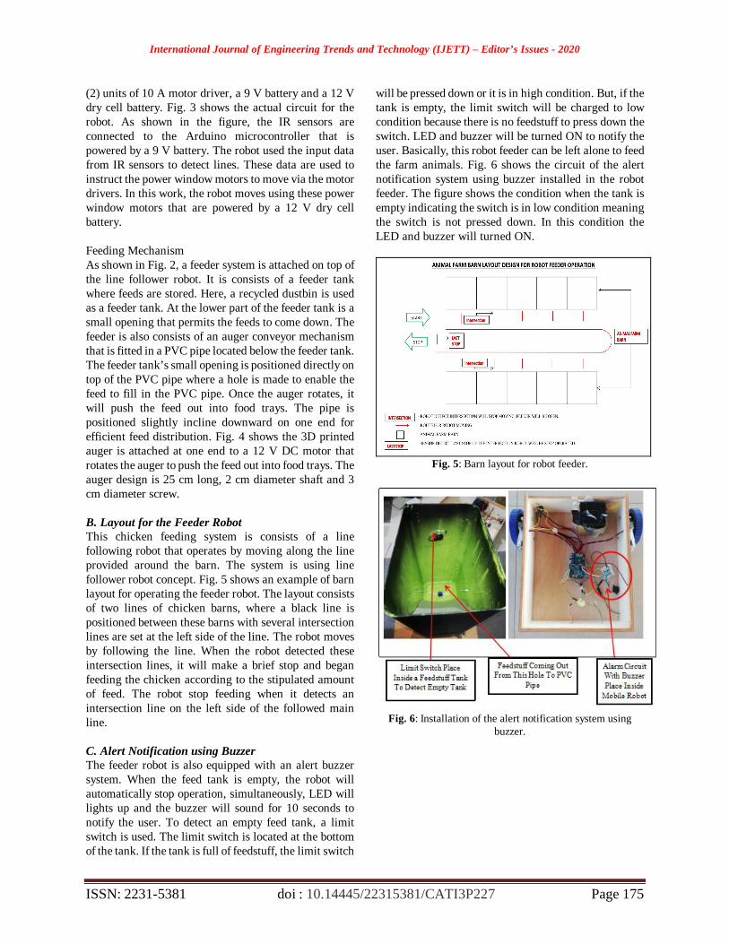
Feeding Mechanism As shown in Fig. 2, a feeder system is attached on top of the line follower robot. It is consists of a feeder tank where feeds are stored. Here, a recycled dustbin is used as a feeder tank. At the lower part of the feeder tank is a small opening that permits the feeds to come down. The feeder is also consists of an auger conveyor mechanism that is fitted in a PVC pipe located below the feeder tank. The feeder tank’s small opening is positioned directly on top of the PVC pipe where a hole is made to enable the feed to fill in the PVC pipe. Once the auger rotates, it will push the feed out into food trays. The pipe is positioned slightly incline downward on one end for efficient feed distribution. Fig. 4 shows the 3D printed auger is attached at one end to a 12 V DC motor that rotates the auger to push the feed out into food trays. The auger design is 25 cm long, 2 cm diameter shaft and 3 cm diameter screw. B. Layout for the Feeder Robot This chicken feeding system is consists of a line following robot that operates by moving along the line provided around the barn. The system is using line follower robot concept. Fig. 5 shows an example of barn layout for operating the feeder robot. The layout consists of two lines of chicken barns, where a black line is positioned between these barns with several intersection lines are set at the left side of the line. The robot moves by following the line. When the robot detected these intersection lines, it will make a brief stop and began feeding the chicken according to the stipulated amount of feed. The robot stop feeding when it detects an intersection line on the left side of the followed main line. C. Alert Notification using Buzzer The feeder robot is also equipped with an alert buzzer system. When the feed tank is empty, the robot will automatically stop operation, simultaneously, LED will lights up and the buzzer will sound for 10 seconds to notify the user. To detect an empty feed tank, a limit switch is used. The limit switch is located at the bottom of the tank. If the tank is full of feedstuff, the limit switch
will be pressed down or it is in high condition. But, if the tank is empty, the limit switch will be charged to low condition because there is no feedstuff to press down the switch. LED and buzzer will be turned ON to notify the user. Basically, this robot feeder can be left alone to feed the farm animals. Fig. 6 shows the circuit of the alert notification system using buzzer installed in the robot feeder. The figure shows the condition when the tank is empty indicating the switch is in low condition meaning the switch is not pressed down. In this condition the LED and buzzer will turned ON.
Fig. 5: Barn layout for robot feeder.
Fig. 6: Installation of the alert notification system using
buzzer.

International Journal of Engineering Trends and Technology (IJETT) – Editor’s Issues - 2020
ISSN: 2231-5381 doi : 10.14445/22315381/CATI3P227 Page 176
Fig. 7: Flowchart for poultry feeding process using the robot
feeder z
Fig. 8:
D. Poultry Feeding Process Fig. 7 shows the flowchart for poultry feeding process using the proposed robot feeder. On the upper right of the figure is an illustration of the IR sensors positions to assist in explaining the method on how the robot reacts when the sensors detect black line and intersection lines. The illustration on the upper right shows A, B and C labels that represent IR module sensors attached on the robot feeder. Here, IR sensors A and B are to sense white surface. When the sensors sense white surface, Arduino
receives 1 as input and black surface provides 0 input. On the other hand, sensor C detects the intersection line (white line) for the robot to stop moving for 10 seconds before starts moving forward again. The robot stops feeding when all the sensors sense black line. The poultry feeding process starts by switching ON the feeder robot. The robot starts to sense black line at the center using sensors A and B. It will move forward when white surface is detected. If sensor A senses a black line, the robot will turn to the left side. However, if sensor B senses a black line, the feeder robot will turn to the right side until both sensors A and B sense white surface where the robot starts moving forward again. The robot stops once all sensors A, B and C sense black line or stop line as shown in Fig. 7. After sensing black line, the robot checks the condition of feedstuff in the feed tank. If the tank is empty, it will stop feeding operation until the tank is filled up. Buzzer will turned ON for 10 seconds, while the LED will lights up to inform human operator of the condition. If the tank is filled up, the feeding mechanism will be turned ON and resume operation after certain amount of time. The robot moves forward by following the line that are detected using sensors A and B. Simultaneously, sensor C detects any intersection line. When sensor C detects an intersection line, the robot stops moving forward and the feeding mechanism starts pushing the feedstuff for certain amount of time that can be set by the user. If all the sensors detects black line, it will stop operating
III. EXPERIMENTAL RESULTS A. Poultry Feeder Robot In this subsection, the final design of the poultry feeder robot is described. Fig. 8 shows the different view of the poultry feeder robot. The developed robot is consists of two (2) power window motor, a 10-amp motor driver shield, two (2) caster wheel, an Arduino UNO microcontroller, three (3) IR sensors, and a 12 V DC motor that is connected to an auger fitted inside a PVC pipe. The feeder mechanism that consists of a feeder tank is attached on the upper side of the line follower robot.
Fig. 9 shows the electronic components inside the line follower robot. The top cover of the line follower robot can be slide open for easy access to the circuit and electronic components inside the robot for maintenance and troubleshoot purposes. The robot is powered by a 12 V battery. As shown in Fig. 9, the battery is located at the backend of the robot to stabilize the balance of the robot movement. A rocket switch is used to switch ON and OFF the robot, where an indicator light is also used to indicate the power is switched ON or OFF. Fig. 10 shows the final design of the poultry feeder robot.
Poultry feeder robot
IR sensors
Stop line
Intersection lines
Black line

International Journal of Engineering Trends and Technology (IJETT) – Editor’s Issues - 2020
ISSN: 2231-5381 doi : 10.14445/22315381/CATI3P227 Page 177
B. Experiment on the Line Follower Robot The developed poultry feeder system is consists of a line follower robot, feeding mechanism and barn layout. Fig. 11(a) shows the developed poultry feeder robot. Fig. 11(b) shows the designed line layout for barn. The layout is for experimental purpose, therefore only a straight line is considered. As shown in Fig. 11(b), the layout consists of two (2) straight black line, one with white intersection lines. At the end of both lines is a horizontal black line where the robot will stop moving.
In this experiment, the robot feeder had been tested to follow the line and stop at every intersection to push out feedstuff. During the test, the sensitivity of IR sensor can be adjusted using the potentiometer to test the efficiency of the IR sensors to detect the lines. Fig. 12 shows the condition during the experiment.
Based on the observation of Fig. 12 the poultry feeder robot had successfully followed the predetermined lines. Fig. 12(a) shows that at time = 0s, the robot will start moving from starting position. Fig. 12(b) shows after 5s, the robot stopped at the first intersection to push out feedstuff. Fig. 12(c) shows the robot stopped at second intersection and lastly, Fig. 12(d) shows the robot stopped at the stop line after 15s.
C. Experiment on the Feeder System Based on Fig. 4 in the previous section, the feeder mechanism is consists of a 3D printed auger that is attached at one end to a 12 V DC motor. The motor rotates the auger to push the feed out into food trays. The 12 V DC motor is connected to a motor driver module and then connected to Arduino Uno to test the speed and time needed to push out the feedstuff.
As described previously, the poultry feeder system uses an IR sensor to detect white intersection lines to instruct the robot to push out the feedstuff. Once the IR senses the intersection, the DC motor rotates about ten seconds to push the feedstuff. Fig. 13(a) shows the location of the IR sensor to detect intersections on the left side of the robot. Fig. 13(b) shows the completed feeder system that consists of a feeder tank and PVC pipe. Several experiments have been conducted to show the effectiveness of the developed auger mechanism to push feedstuff out. Furthermore, the experiments were also to verify the time taken by the motor to rotate the auger for feedstuff output. Based on the experiments, the feeder system has been successfully push out feedstuff according to the predetermined intersection lines.
(a) Front view (b) Back view (c) Side view (d) top view
Fig. 8: Various views of the poultry feeder robot.

International Journal of Engineering Trends and Technology (IJETT) – Editor’s Issues - 2020
ISSN: 2231-5381 doi : 10.14445/22315381/CATI3P227 Page 178
Fig. 9: Electronic circuitry Fig. 10: Poultry feeder robot
(a) Poultry feeder robot (b) Barn line layout design
Fig. 11: Poultry feeder robot. (a) time = 0s (b) time = 5s (c) time = 10s (d) time = 15s
Fig. 12: Time histories showing the movement of robot
feeder.
(a) (b)
Fig. 13: (a) IR sensor for intersection line detection and, (b) the end product of the feeder system.
Power window motors
Wires to IR sensors Alarm circuit
with buzzer
12 V battery
ON/OFF switch
Arduino with motor driver

International Journal of Engineering Trends and Technology (IJETT) – Editor’s Issues - 2020
ISSN: 2231-5381 doi : 10.14445/22315381/CATI3P227 Page 179
IV. CONCLUSION
As a conclusion, this work described the design and development of a robotic poultry feeder system consists of a line follower robot, automated feeder mechanism and line layout for barn. In this work, the performance of the proposed system has been experimented through using actual experiments. The propose system take into consideration a simplistic design and system that makes it easy for users to interact with low development cost.
For future improvements, the robot will be improved by increasing the number of sensors and better sensors such as photoelectric sensor will be utilized to improve line detection. Solar power will also be used in future design so that it can be operated for longer periods of time. In addition, this robot feeder can be developed further by adding more application such as Internet of Thing (IoT) and Global System for Mobile Communications (GSM) to notify the user the condition of feeding process.
ACKNOWLEDGEMENT The authors would like to thank the Research Management Center (RMC), UTHM and Ministry of Higher Education for sponsoring the research under Tier 1 Research Grant (H161).
REFERENCES [1] N. S. Samsuddin et al, “Sustainability of Chicken Meat
Production in Achieving Food Security in Malaysia,” Advances in Environmental Biology, 9 (23): 1-6, 2015.
[2] V. Veleva, M. Hart, C. Greiner, C. Crumbley, “Indicators of sustainable Production,” J. Clean.Prod.,9:447e452, 2001
[3] M. S. Nazmi et al., “Broiler Industry in Malaysia,” FFTC Agricultural Policy Articles (FFTC-AP): Production Policy. Available: http://ap.fftc.agnet.org/ap_db.php?id=532&print=1
[4] TNAU Agritech Portal. System of Poultry Rearing. Available: http://agritech.tnau.ac.in/animal_husbandry/ani_chik_poultry%20rearing.html
[5] O. E. Oke, A. O. Ladokun, O. M. Onagbesan, “Reproductive performance of layer chickens reared on deep litter system with or without access to grass or legume pasture,” J Anim Physiol Anim Nutr, 100: 229-235, 2016.
[6] W. Run-zhi, “Effects of Deep-litter System on Growth Performance of Quality Chickens and on Coop Environment,” Journal of Anhui Agricultural Sciences, 2014-07.
[7] F. Mbuza et al. “Characterization of broiler poultry production system in Rwanda,” Trop Anim Health Prod (2017) 49: 71.
[8] M.. N Al-Ajeeli et al., “Evaluation of the performance of Hy-Line Brown laying hens fed soybean or soybean-free diets using cage or free-range rearing systems,” Poultry Science, Vol. 97, Issue 3, pp. 812–819, 2018.
[9] Y. Aral et al., “Economic comparison of unenriched and alternative cage systems used in laying hen husbandry - recent experience under Turkish commercial conditions,” World's Poultry Science Journal, 73(1): 69-76, 2017