development of a novel aerial platform which …€¦ · keywords: tethered airship, design and...
TRANSCRIPT

DEVELOPMENT OF A NOVEL AERIAL PLATFORM WHICHMERGES THE CONCEPT OF AIRSHIPS AND TETHERED
AEROSTATS
Jônatas S. Santos∗, Bruno A. de Azevedo∗, Luiz C. S. Góes∗, Rajkumar S. Pant∗∗∗Instituto Tecnológico de Aeronáutica (ITA), São José dos Campos, São Paulo, 12228-900, Brasil,
∗∗Indian Institute of Technology Bombay (IIT), Mumbai, Maharashtra, 400076, India
Keywords: Tethered airship, design and fabrication, unmanned airship, LTA platform, tethered aerostat.
Abstract
This paper proposes a novel LTA platform, thetethered airship that is a merge of airship andtethered aerostat functionalities, combining thenavigation abilities of airships and the hover-ing performance of tethered aerostats that is de-signed to remain stationary in high wind condi-tions, to transfer data with high speed data linkto the ground base through an electric tether andto fly unlimited time periods. This paper presentsthe sizing based in a scaled model of the YEZ-2A airship, the designing and fabrication of eachcomponent, and the integration that originates thenovel tethered airship prototype in which it is val-idated through flight experiments.
1 Introduction
This paper aims to feel part of the gap betweenthe airship and the tethered aerostat vehicles.This investigation covers the tethered airshipmodeling, designing, manufacturing and assem-bling process, validating the prototype throughflight experiments. The final goal of this researchis to develop autonomous flight capabilities ofan airship attached to the ground by a thin ca-ble. The concept is to have an airship that canbe eventually connected to the ground through atether, or in an opposite way, a tethered aerostatequipped with a propulsion system that can even-tually perform free flight.
A lot of work has already been done in vari-
ous projects related to unmanned airships, suchas AURORA in Brazil in late 90s [1] [3] [10][1] [2], Autonomous Airship of LAAS/CNRS [6][7] [5] LOTTE airship in Germany [14], KARIin Korea [8] [9], DIVA in Portugal [11] and Au-tonomous Outdoor Airship Project in IIT Bom-bay [12]. The common drawback is that all theseairships were sensitive to the atmosphere condi-tions, especially to wind gusts[13].
The main benefits of the tethered airship arethe expansion of flight envelope of airships, en-abling to hover in a high wind speed condi-tion (station keeping), the mobility and agilityto tethered aerostat operations when it is mov-ing between hangars or to a different mooringsystem location (autonomy), perform flight ina constrained area limited by the length of thetether (safety), it allows mid-air charging andhigh speed data link via electric cable (commu-nication solutions and unlimited endurance).
In the sequence of this paper, the tethered air-ship concept is introduced and the sizing processfor obtaining a model is described in section 2.The design and fabrication of the main compo-nents of the vehicle are detailed in section 3. Pre-liminary flight test results are presented in section4, and conclusions are made in section 5.
2 Tethered Airship Concept and model
A tethered airship is a flight vehicle that has staticlift, can perform navigation, and can connect anddisconnect to a surface using a single tether with
1

JÔNATAS S. SANTOS, BRUNO A. DE AZEVEDO, LUIZ C. S. GÓES, RAJKUMAR S. PANT
an anchoring device. More specifically, the staticlift comes from the Archimedes principle, wherethe magnitude of the buoyant force is equivalentto the weight of the fluid displaced by the body;controllable flight means the ability of track a de-sirable trajectory using actuators in a tethered anduntethered condition; and the surface is any ter-rain in solid or liquid state.
There are many combination of shapes andcomponents that can generate a tether airship ve-hicle. In this paper, the tethered airship is charac-terized by five main components listed below andthey displayed in Fig. 1.
1. Envelope
2. Gondola
3. Fins
4. Tail engine support
5. Tether system
The envelope is designed to retain the liftinggas and to support external loads. The gondolais a rigid support installed on the belly of the air-ship. It is used to carry the propulsion system,batteries, avionics and the payload. Fins are usedfor stabilization and maneuverability of the air-ship dynamic model by changing magnitudes anddirections of aerodynamic vectors. The tail en-gine support is used to care two engines and pro-pellers and it is designed to support load of thethrust force in order to steer the airship in lateraldirection. Lastly, the tether system is composedby a series of ropes joined in a confluence pointwith a single tether that anchors the airship to theground.
The tethered airship with these main compo-nents is able to perform a controllable free flightand to be a station keeping while using the tethersystem.
In order to design a tethered airship, it waschosen a scaled model of the YEZ-2A airship be-cause its dynamic behavior was investigated byGomes [4] and its aerodynamics was obtained bywind tunnel data. The original profile and airshipsizing is displayed in Fig. 2.
Fig. 1 Tethered airship concept.
Fig. 2 YEZ-2A Airship.
The three-dimensional model presented inFig. 3 was built in CATIA using a scalingfactor designed in a multi-criteria optimizationbased in operational requirements, as of mini-mum payload weight of 15 kgf, maximum ex-ternal dimensions in view of transportation pur-poses and hangar sizing, handling procedures andwinch maximum operational loads at 100 metersof height.
Fig. 3 Airship scaled CAD Model.
The result was a scaled airship with the gen-eral parameters presented in Table 1. The dimen-
2
DEVELOPMENT OF A NOVEL AERIAL PLATFORM WHICH MERGES THE CONCEPT OFAIRSHIPS AND TETHERED AEROSTATS
sional values were obtained by the scaled CADmodel, and forces were calculated consideringInternational Standard Atmosphere (ISA) at sealevel. For the avionics, the maximum weight ofall electronic systems including batteries is 10kgf. The Payload consists in the sensor e.g. cam-era, radio, sonar, and in the electronic system be-longing to the sensor operational system. TheNet Lift is the upward force that remains, ant itis balanced by the tether weight, estimated to be4 kgf each 100 meters length, and tether tension.
Table 1 Tethered Airship parameters.Parameter Value Unit
Length 12.3 mMaximum Diameter 3 mVolume 60 m3
Surface Area 86 m2
Avionics 10 kgfPayload 20 kgfNet Lift 5 kgf
Once the dimensions and weights are defined,the process of design and fabrication of eachcomponent starts.
3 Design and Fabrication of Components
This section presents the design and fabricationof each main component of a tether airship, con-sidering the established dimensions. Those com-ponents are envelope, gondola, fins, tail enginesupport and tether system.
At the end of this chapter, the prototype inte-gration is presented and the comparison betweenactual and 3D model are made.
3.1 Envelope
The envelope is built with two layers. The inter-nal one has the function of retaining the liftinggas, and the external one is designed to supporthigh loads due to tether tension and aerodynamicforces. The envelop is divided in 10 equal parts,called petals, which are welded using a sealingmachine.
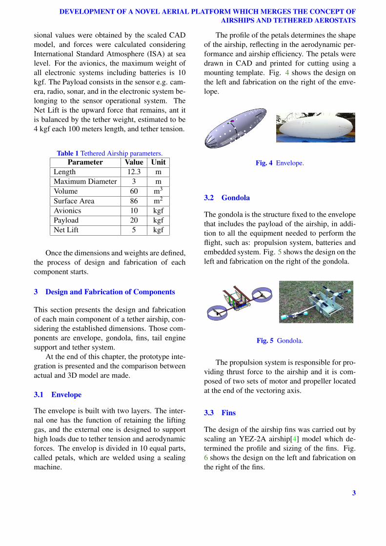
The profile of the petals determines the shapeof the airship, reflecting in the aerodynamic per-formance and airship efficiency. The petals weredrawn in CAD and printed for cutting using amounting template. Fig. 4 shows the design onthe left and fabrication on the right of the enve-lope.
Fig. 4 Envelope.
3.2 Gondola
The gondola is the structure fixed to the envelopethat includes the payload of the airship, in addi-tion to all the equipment needed to perform theflight, such as: propulsion system, batteries andembedded system. Fig. 5 shows the design on theleft and fabrication on the right of the gondola.
Fig. 5 Gondola.
The propulsion system is responsible for pro-viding thrust force to the airship and it is com-posed of two sets of motor and propeller locatedat the end of the vectoring axis.
3.3 Fins
The design of the airship fins was carried out byscaling an YEZ-2A airship[4] model which de-termined the profile and sizing of the fins. Fig.6 shows the design on the left and fabrication onthe right of the fins.
3

JÔNATAS S. SANTOS, BRUNO A. DE AZEVEDO, LUIZ C. S. GÓES, RAJKUMAR S. PANT
Fig. 6 Fins.
3.4 Tail Engine Support
The tail rotor parts were manufactured by the wa-ter jet cutting process. The main frame is made ofaluminum, reinforced with fiberglass tubes. Thefixing is through balsa wood to support the enve-lope, Velcro and cables for its stabilization.
Fig. 7 Tail engine support.
In this structure, 2 brushless motors are in-stalled in opposite directions to promote lateralforce on the tail of the dirigible in both direc-tions. Each engine will have independent oper-ation, providing a maximum lateral thrust of 3kgf.
3.5 Tether system and prototype
The tether system is composed by eight linesmade by Kevlar. Their dimensions are obtainedby the distance from attachment point at the en-velope to the confluence point, where all the ca-bles are joined to a single tether that anchors theairship to the ground.
The conclusion of the mechanical design wasachieved with the integration of all componentsand with the preparation of the airship anchoredto flight by inflating with helium gas. The com-parison between the model and the prototype is
Fig. 8 Tether system attached to the airship.
shown in the Fig. 9.
Fig. 9 Comparison between design and prototype.
4 Flight experiments
The aim of the first flight experiment was to ver-ify the airship dynamic behavior. The envelopewas filled with helium gas and all componentswere attached. The tethered airship prototype isdisplayed in Fig. 10 where the envelope, gon-dola, fins and the tether system can be observed.
The altitude of the experiment was 650 me-ters, a ballast of 15 kgf was attached to the gon-dola in order to simulate the payload weight. Bal-last in the nose less than 1 kgf was added for trim-ming purposes. The weight of Avionics was 9 kgf
4

DEVELOPMENT OF A NOVEL AERIAL PLATFORM WHICH MERGES THE CONCEPT OFAIRSHIPS AND TETHERED AEROSTATS
and the Net Lift was 12.5 kgf. Taking into ac-count the weight of the tether and the variation ofaltitude, it was verified the possibility to operateat 100 meters of height from the ground station.
Fig. 10 Tethered airship prototype.
Furthermore, the static equilibrium wasachieved in this flight experiment and a stablebehavior was observed in winds lower than 3m/s. Oscillations in yaw direction was observedin winds between 3 and 6 m/s and improvementson the design of the tethered airship can be madein order to reduce the oscillatory behavior. Thiswill be a further step that will optimize the teth-ered airship to be designed for working in a largerange of windspeed, allowing to extend its auton-omy, flying for extended periods due to low en-ergy consumption for fighting against wind dis-turbances and for adding the capability of refuel-ing or recharging batteries while tethered.
The preliminary design and fabrication werevalidated in this flight experiment and the explo-ration of the capabilities of this platform was ini-tiated.
5 Conclusions
The development of a tethered airship was pre-sented. The concept to have a platform speciallydesigned and adapted for both performing navi-gation and being a station keeping while tetheredin the ground was introduced. As ships need ananchor for holding a specific position, the sameconcept was proposed for an unmanned airship.
This paper also detailed the methodologyused for conceiving a tethered airship, startingfrom sizing, design to manufacturing and integra-tion. A preliminary flight test results were alsopresented. The concept of operation, consideringtrimming, assembling and flying a tethered air-ship was validated through flight experiments.
Now that the platform is established, im-provements are suggested as future works: theadaptation of system identification methodolo-gies for this platform aiming to have a high-fidelity model; improvements of the dynamicsystem stability by developing an active controlor designing an optimal size of tail fins for guar-antee passive stability in a large range of windgust; developing an autonomous navigation sys-tem that considers the constrains imposed by thetether; expand the autonomy of airships by us-ing a tether to perform refueling operations, toaid takeoff and landing in windy condition and totransform the airship in a steady station keepingfor persistent in-flight operations.
References
[1] S.S. Bueno, J.R. Azinheira, J.G. Ramos, E. C.de Paiva, P. Rives, A. Elfes, J.R.H. Carvalho,and G. F. Silveira. Project aurora-towards anautonomous robotic airship. In Workshop onAerial Robotics, IEEE/RSJ International Con-ference on Intelligent Robots and Systems -IROS, 2002.
[2] Ely Carneiro de Paiva, Jose Raul Azinheira,Josue G. Ramos, Alexandra Moutinho, andSamuel Siqueira Bueno. Project aurora infras-tructure and flight control experiments for arobotic airship. Journal of Field Robotics, 23(3-4), 2006.
[3] Alberto Elfes, Samuel Bueno, Josue Ramos,Ely Carneiro de Paiva, Marcel Bergerman, JoséR. H. Carvalho, Silvio M. Maeta, Luiz Gus-tavo Bizarro Mirisola, Bruno G. Faria, andJosé Raul Azinheira. Modelling, control andperception for an autonomous robotic airship. InSensor Based Intelligent Robots, InternationalWorkshop, Dagstuhl Castle, Germany, October15-20, 2000 Selected Revised Papers, 2000.
[4] S. B. V. Gomes. An Investigation of the Flight
5

JÔNATAS S. SANTOS, BRUNO A. DE AZEVEDO, LUIZ C. S. GÓES, RAJKUMAR S. PANT
Dynamics of Airships with Application to theYEZ-2A. PhD thesis, Cranfield Institute ofTechnology, College of Aeronautics, Cranfield,1990.
[5] E. Hygounenc, I. K. Jung, P. Soueres, andS. Lacroix. The autonomous blimp projectof laas-cnrs: Achievements in flight controland terrain mapping. International Journal ofRobotic Research, 23(4-5):473–511, 2004.
[6] S Lacroix. Towards autonomous airships: re-search and developments at laas/cnrs. In Pro-ceedings of 3rd International Airship Conven-tion and Exhibition, Friedrichshafen, Germany,July 2000.
[7] S Lacroix, I K Jung, P Soueres, E Hygounenc,and J P Berry. The autonomous blimp projectof laas cnrs current status and research chal-lenges. In B. Siciliano and P. Dario, editors,Experimental Robotics VIII, Ischia (Italy), Lec-ture Notes in Control and Information Sciences,pages 422–443. Springer Tracts in AdvancedRobotics, October 2003.
[8] G. Y. Lee, D. M. Kim, and C. H. Yeom. De-velopment of korean high altitude platform sys-tems. International Journal of Wireless Infor-mation Networks, 13(1):31–42, January 2006.
[9] S. J. Lee, S. P. Kim, T. S. Kim, H. K. Kim, andH. C. Lee. Development of autonomous flightcontrol system for 50 m unmanned airship. InProceedings of IEEE ISSNIP-2004, pages 457–462, 2004.
[10] A Moutinho and Jose Raul Azinheira. Stabil-ity and robustness analysis of the aurora air-ship control system using dynamic inversion.In Proceedings of the 2005 IEEE InternationalConference on Robotics and Automation, ICRA,pages 2265–2270, 2005.
[11] A. B. Moutinho. Modeling and Nonlinear Con-trol for Airship Autonomous Flight. phdthesis,Institute of Mechanical Engineering (IDMEC)in Instituto Superior Tecnico, Technical Univer-sity of Lisbon, 2007.
[12] J. S. Santos, L. C. S. Goes, and R. S. Pant. De-sign and flight testing of an autonomous airship.In 22nd AIAA Lighter-Than-Air Systems Tech-nology Conference, USA, 2015.
[13] J S Santos, S Stevanovic, K Kondak,F Holzapfel, L C S Goes, and R S Pant.
Stability augmentation system for a teth-ered airship. In Proceedings from the 16thAIAA Lighter-Than-Air Systems TechnologyConference, AIAA, Washington, DC, 2016.
[14] D. A. Wimmer, M. Bildstein, K. H. Well,M. Schlenker, P. Kungl, and B. H. Kroplin.Research airship lotte development and opera-tion controllers for autonomous flight phases.In Workshop on Aerial Robotics, IEEE Inter-national Conference on Intelligent Robots andSystems, Lausanne, Switzerland, pages 55–68,2002.
Acknowledgement
This research was sponsored by the Con-selho Nacional de Desenvolvimento Científicoe Tecnológico - CNPq and Coordenação deAperfeiçoamento de Pessoal - CAPES throughScience Without Borders under grants no
141680/2014-8 and PVE process no 045/2012,and Fundação de Amparo à Pesquisa do Estadode São Paulo - FAPESP, under PIPE processno2015/00704-3 and no15/50625-2, which aresupporting the ongoing tethered airship project.
Contact Author Email Address
Authors’ email addresses for questions concern-ing the content of this paper are presented.
mailto: [email protected]: [email protected]: [email protected]: [email protected]
Copyright Statement
The authors confirm that they, and/or their companyor organization, hold copyright on all of the origi-nal material included in this paper. The authors alsoconfirm that they have obtained permission, from thecopyright holder of any third party material includedin this paper, to publish it as part of their paper. Theauthors confirm that they give permission, or have ob-tained permission from the copyright holder of thispaper, for the publication and distribution of this pa-per as part of the ICAS proceedings or as individualoff-prints from the proceedings.
6