development of a multi-modal, flexible tactile sensing ... · development of a multi-modal,...
TRANSCRIPT

DEVELOPMENT OF A MULTI-MODAL, FLEXIBLE TACTILE SENSING SKIN USING POLYMER MICROMACHINING
Jonathan Engel, Jack Chen, and Chang Liu
Micro and Nanotechnology Laboratory, University of Illinois at Urbana-Champaign
ABSTRACT Inspired by the superior functionality of biological skin,
we report a first multi-modal, flexible, and robust tactile sensing skin based on polymer substrates. The demonstrated device successfully incorporates multiple sensor modalities into a compact “node” for evaluating contact forces and film curvature, as well as the relative hardness, thermal conductivity, and temperature of the contacted object. Sensing is accomplished via thin film metal gold heaters, nickel RTDs (Resistance Temperature Device), and NiCr (nichrome) strain gauges. Built on a micromachined polyimide (DuPont Kapton HN200) film, the sensors provide qualitative measurements of contact object properties. Experimental characterization of the sensors’ performance is presented.
INTRODUCTION
In order for robotics to replace or serve as extensions of humans in dangerous, delicate, or remote applications they must have sensory input similar to or superior to the human senses. One of the most important senses for performing varied complex and precise tasks autonomously or remotely is the sense of touch. Tactile feedback from the human skin provides a multitude of information, including force, temperature, hardness, texture, and thermal conductivity [1]. To date, robots do not have the sensing capability to provide them with an equivalent sense of “touch”.
A large body of work has been performed to create artificial sensors that provide force imaging and measurement. These consist of silicon based sensors that use piezoresistive or capacitive sensing, and polymer-based approaches that use piezoelectric polymer films for sensing [2,3,4,5]. Work has also been performed towards matching the multi-modal capabilities of the human skin, with devices reported that measure contact force and hardness as well as contact force and object thermal properties [6,7].
Devices that incorporate brittle sensing elements such as silicon-based diaphragms or piezoresistors, even embedded in protective polymers, cannot be used as the interface “skin” between a robotic manipulator and the manipulated object. Devices made with pressure sensitive rubbers that can withstand contact have been presented, but require serial manual assembly, are based on rigid substrates and provide limited independent sensing modes [7]. In an effort to overcome these limitations, we present a tough, monolithic polymer-based sensing skin that incorporates a number of metal film sensors.
MULTI-MODAL SENSING SKIN
The reported device is fabricated on DuPont Kapton HN200 2-mil-thick polyimide film. The use of a polymer substrate allows flexibility, robustness, and low material
cost. Our device is comprised of four distinct sensors, a reference nickel RTD for temperature measurement and compensation, a gold heater and nickel RTD pair for thermal conductivity measurement, a membrane NiCr strain-gauge based contact force and hardness sensor, and a reference contact hardness sensor (Fig 1a). In addition, the contour of the skin is sensed in an integrated fashion using NiCr strain gauges dispersed between sensory nodes (Fig 1b). When the skin is mounted on a curved or compliant surface (e.g., a robotic finger tip), the spatial relation of sensor nodes is mapped to coordinate manipulation in 3D space. To the best of our knowledge, the development, integration, and characterization of thermal conductivity, hardness, and curvature sensors using polymer micromachining has not been previously achieved. Each sensing aspect is now discussed in detail.
Figure 1) a) A sensory node incorporates 4 distinct sensors 1: reference temperature sensor, 2: thermal conductivity sensor, 3 and 4: contact force and hardness sensors. b) Sensor nodes are arranged in an array to form skin, with skin mapping sensors between nodes.
A. Temperature Sensing
Incorporated in our sensing skin is a nickel RTD (Fig 1a) that is used to measure the temperature of the operating environment as well as contact objects. This information is important for temperature compensation of the measurements of the other sensors as well as providing contact object information. Since all the sensors incorporated on the demonstrated sensing skin are based on thin film metal resistors, all of them will function as RTD’s to one extent or another based on the TCR (thermal coefficient of resistance) of the base material. This value is low for NiCr, making it a good choice for rejecting thermal disturbances, but is high for nickel and gold. Gold is not used for the RTD due to its low resistivity. By using nickel, we can get a high TCR with the added benefit of increased resistivity to decrease the effect of parasitic resistances.
B. Hardness Sensing
Existing micromachined hardness sensors require the applied force be known, use a known calibrated integral actuator force, or use changing resonant frequency under ultrasonic vibration [6,7]. The required assumptions, complexity, and size limitations of such approaches do not lend themselves to a distributed multi-modal skin. We have
3B2.1
TRANSDUCERS ‘03The 12th International Conference on Solid State Sensors, Actuators and Microsystems, Boston, June 8-12, 2003
0-7803-7731-1/03/$17.00 ©2003 IEEE 1027

developed a passive hardness sensor that does not rely on actuation or knowledge of contact force.
Figure 2) a) Cross section of hardness sensor, with membrane and bulk hardness sensors, b) in contact with an object, the sensors deform, with apparent pressures proportional to the contact object hardness.
Figure 3) a) Micrograph of membrane hardness sensor with NiCr strain gauge, and b) of reference bulk sensor.
The structure of the demonstrated hardness sensor
within the sensor “node” is shown in Figure 1a and in cross section in Figure 2a. The device consists of a measurement sensor on a polymer diaphragm and reference sensor on the bulk polymer substrate. Both sensors include a contact mesa as shown in Figure 2a with strain gauges situated on the periphery of these mesas (Fig. 3). The square measurement diaphragm has a relatively low stiffness and for a given maximum central displacement requires a uniform pressure according to clamped-clamped plate theory as shown in Eq. 1 [8].
4
3max
plate(0.0138)b
tEq
z= (1)
Where zmax is the peak vertical deflection in the center of the diaphragm, qplate is the pressure applied to the plate, b is the length of the square sides, E is the material modulus, and t is the plate thickness.
The reference sensor does not use a diaphragm; rather the contact mesa and strain gauges are positioned over full thickness bulk polymer (Fig. 2a, and 3b). The stiffness of the bulk reference sensor is thus much higher than the measurement diaphragm. The sensor requires a uniform pressure for a given deflection according to Eq. 2 [9].
) -(1 a (2.24)
E2
max
νz
qbulk = (2)
Where ν is the bulk material Poisson’s ratio, a is the contact mesa width, and qbulk is the pressure applied to the bulk
sensor contact mesa. This model assumes that the reference sensor behaves like a semi-infinite block under a uniform pressure over the area of the contact mesa. With a film thickness of 50µm and deflections on the order of 0.1-1.0µm this assumption may not be valid and further modeling required.
When the sensor skin is in contact with an object, changes in resistance are observed at both the measurement and reference sensor strain gauges (Fig 2b). The measured resistance changes are converted to a peak deflection (zmax) with calibrated resistance versus displacement data and used to find the apparent pressures qplate and qbulk with Eq 1 and 2. Under device operation it is found that the contact object hardness is proportional to the ratio of apparent pressures.
Measurement of contact forces can also be performed using the same polymer diaphragm and bulk sensors. Based on the known geometry of the devices, the pressures can be equated to normal force. The differential stiffness of the two sensors allows two different ranges of contact forces to be measured.
C. Thermal Conductivity Sensing
The thermal conductivity sensor operates by observing the changing resistance of the nickel RTD in response to an input to the gold heater. The thermal conductivity of a contacting object is a useful measure for object discrimination, and in concert with other sensing modes can expand the capabilities of the overall skin by helping to distinguish between equally “hard” objects for example.
To accomplish this measurement, the demonstrated sensor consists of a gold heater situated near a nickel RTD (Fig 1a). When not in contact with an object, the only route for the heat input of the heater to reach the RTD is through the polyimide substrate and the surrounding air. When an object comes in contact with the sensor, the low efficiency heat path through the air is replaced by solid conduction, changing the character of the signal measured at the nickel RTD. With a square wave voltage input to the heater, the change in temperature of the RTD can be modeled as a simple first order system according to Eq 3.
τ/1)( tRTD etT −−=∆ (3)
Where is the time constant of the first order system, giving a measure of how quickly the system responds to an input. The time constant of the RTD temperature is found to be a function of contact object thermal conductivity. This method is relatively computationally intensive but was found to correlate well to contact object thermal conductivity.
D. Film Curvature Sensing
Integrated NiCr strain gauges dispersed between sensor nodes measure the x and y-direction curvature of the flexible skin (Fig 1b). The gauges are positioned over trenches etched in the back of the polyimide to allow the film to preferentially bend in these regions. Processing of these measurements into bending angles using calibrated data allows a three-dimensional mapping of skin curvature state. This modality has no direct analog in the biological realm
3B2.1
TRANSDUCERS ‘03The 12th International Conference on Solid State Sensors, Actuators and Microsystems, Boston, June 8-12, 2003
0-7803-7731-1/03/$17.00 ©2003 IEEE 1028
but is akin to the “body awareness” that allows us to locate our limbs without visual confirmation.
SKIN FABRICATION
First, a 50mm square is cut from a sheet of DuPont Kapton HN200 polyimide film. During the fabrication of the Kapton film at DuPont, one surface of the film is in contact with rollers and the other untouched. In practice, measurements with an optical vertical scanning interferometer (VEECO LM1000) showed very small roughness differences between the free and roller faces (197nm and 243nm Rq respectively).
Figure 4) Device fabrication: a) aluminum etch mask deposition, b) RIE etching of polyimide, c) thermal contact mesa patterning, d) NiCr strain gauge, Ni RTD, and Au wiring deposition, and e) tactile contact mesa patterning.
Once the film is baked out, an aluminum etch mask is
deposited and patterned via lift off on the “rough” roller side of the film (Figure 4a). The 50µm-thick film is etched 40µm down in an RIE oxygen plasma at 350W under 300mT O2 (Figure 4b) to define the flex channels and sensor diaphragms. This plasma-etching step is performed first to avoid erosion of backside metal layers that was observed when oxygen plasma etching was performed as the final processing step.
Next, a 2µm layer of photo-definable polyimide (HD Microsystems HD4000) is spun on the smoother top skin surface and patterned to define contact mesas for the thermal conductivity and reference RTD sensors (Figure 4c). The polyimide layer is cured under 1 Torr of nitrogen at 350˚C for 2 hours.
Nickel RTDs (500Å Ni on 100Å Cr) are then deposited and patterned on the contact mesas. Then, 750Å of NiCr is deposited and lifted off to define the strain gauges for the force, curvature, and hardness sensors. No adhesion layer is used. The last metal layer consists of 1500Å of Au on 100Å Cr that is thermally evaporated and lifted off (Fig 4d). Before each metal deposition step, the skin is placed in an oxygen planar plasma for 3 minutes at 300W to remove photo resist residue from image reversal and to improve metal adhesion to the polymer film. In order to achieve the relatively high resolution required for the minimum NiCr (10µm) and Ni (15µm) feature widths on a flexible polymer substrate, we temporarily attach the Kapton film to a Pyrex substrate via surface tension by wetting the substrate with a drop of de-ionized water.
The final step is to spin on, pattern, and cure the 8µm HD4000 contact bumps for the force and hardness sensors (Fig 4e). A photo of the completed sensor skin is seen in
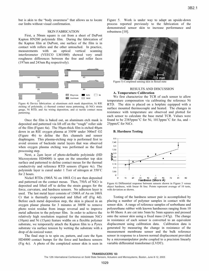
Figure 5. Work is under way to adapt an upside-down process reported previously to the fabrication of the demonstrated sensor skin to increase performance and robustness [10].
Figure 5) Completed sensing skin in flexed state
RESULTS AND DISCUSSION
A. Temperature Calibration
We first characterize the TCR of each sensor to allow temperature compensation via calibrating the reference Ni RTD. The skin is placed on a hotplate equipped with a surface mounted thermocouple and heated. The changes in resistance with temperature are observed and plotted for each sensor to calculate the base metal TCR. Values were found to be 2385ppm/˚C for Ni, 1013ppm/˚C for Au, and –25ppm/C for NiCr.
B. Hardness Testing
Figure 6) Differential response between sensors shown in Figure 3 versus object hardness, with linear fit line. Points represent average of 10 tests, with deviation as shown.
Testing of the hardness sensor pair is accomplished by
placing a number of polymer samples in contact with the sensor skin. A range of reference samples of sorbothane and polyurethane rubber with known hardnesses ranging from 10 to 80 Shore A are cut into 5mm by 5mm squares and pressed onto the sensor skin using a fixed mass (147g). The change in resistance of each sensor is converted to an equivalent displacement using calibration data. Calibration data is generated by measuring the change in resistance of the measurement membrane sensor and the bulk reference sensor in response to a known normal displacement provided by a micromanipulator probe coupled to a precision linearly variable differential transformer (LVDT).
3B2.1
TRANSDUCERS ‘03The 12th International Conference on Solid State Sensors, Actuators and Microsystems, Boston, June 8-12, 2003
0-7803-7731-1/03/$17.00 ©2003 IEEE 1029

The proportionality between pressure ratio and object hardness is shown in Figure 6. A large amount of scatter was observed in the hardness data as can be seen in the figure. This is attributable to the surface roughness of the rubber samples. Non-ideal contact arrangements where asperities contact the bumps in a skewed way such that the change in resistance is opposite to that expected are observed. Nevertheless, a clear overall trend is observed when a large number of data points are averaged as in Fig 6, showing an increase in pressure ratio with object hardness.
C. Thermal Conductivity Testing
Characterization of the performance of the thermal conductivity sensor is performed at room temperature (~22˚C) by inputting a 0-2VDC square wave at 0.3 Hz to the gold heater and measuring the resulting change in resistance of the nearby Ni RTD. The resistance of the RTD is sampled at 10 Hz using an Agilent 34401A multi-meter and GPIB interface.
The sensor should behave as a first order system with a time constant related to the object thermal conductivity. Figure 7 shows the result of testing, where contact objects of various thermal conductivities (nylon 6, soda-lime glass, single crystal silicon, 300-series stainless steel, aluminum, and ambient air) were placed in contact with the sensor skin and the time constant of the resulting RTD signal was obtained through curve fitting. It is observed that the time constant decreases and the step response of the RTD temperature is faster with increasing thermal conductivity. Scatter is observed and expected due to changes in contact configuration from test to test due to surface roughness.
The relationship between object thermal conductivity and time constant is found to be approximately logarithmic based on a curve fit of Figure 7. As a result attempts to formulate a simple electrical analogue model were not successful. We also hypothesized that the steady state temperature reached by the RTD would correlate to object properties but testing showed that the relationship was not monotonic with thermal conductivity, diffusivity, or other characteristic value.
Figure 7) Step power input to gold heater generates signal at nickel RTD with time constant that varies with contact object thermal conductivity. More conductive objects result in faster response and smaller time constant.
D. Skin Curvature Testing
Skin curvature calibration is accomplished by flexing the skin under known displacement using a micro-
manipulator and LVDT. Measurements are taken while bending and relaxing to assess viscoelastic hysteresis and plastic deformation. The resulting sensor response versus skin flex for a number of tests is seen in Figure 8.
Figure 8) Response of skin-mapping sensor to skin curvature.
CONCLUSIONS
The demonstrated sensor skin incorporates a standard sensory “node” that is composed of temperature, hardness, force, thermal conductivity, and curvature sensors. The nodes are repeated over the skin to facilitate multi-point object identification and handling. Fabricated on a low-cost flexible Kapton substrate, the devices offer robust performance. Work is under way to utilize an inverted fabrication technique to enhance device robustness and performance and to allow distributed data handling.
ACKNOWLEDGEMENTS This material is based upon work supported by the National Science Foundation under Grant No. NSF IIS 00-80639.
REFERENCES [1] M.H. Lee, H.R. Nicholls, “Tactile sensing for mechatronics – a state of the art survey,” Mechatronics, Vol. 9, pp 1-33, 1999. [2] B.J. Kane, M.R. Cutkosky, and T.A. Kovacs “A traction stress sensor array for use in high-resolution robotic tactile imaging” Journal of MEMS, Vol. 9, pp. 425-434, 2000. [3] B.L. Gray and R.S. Fearing, “A surface micromachined microtactile sensor array” Proc 1996 IEEE Int’l Conf. On Robotics and Automation, pp. 1-6. [4] E.S. Kolesar and C.S. Dyson, “Object imaging with a piezoelectric robotic tactile sensor,” Journal of MEMS, Vol. 4, pp. 87-96, 1995. [5] F. Jiang, Y-C. Tai, K. Walsh, T. Tsao, G-B. Lee, C-M. Ho, “A flexible MEMS technology and its first application to shear stress sensor skin,” Proc 1997 IEEE Int’l Conf. On MEMS, pp. 465-470. [6] T. Shimizu, M. Shikida, K. Sato, and K. Itoigawa, “A new type of tactile sensor detecting contact force and hardness of an object,” Proc 2002 IEEE Int’l Conf. On MEMS, pp 344-347. [7] K. Shida and J.I. Yuji, “Discrimination of Material Property by Pressure-Conductive Rubber Sheet Sensor with Multi-sensing Function,” Proc 1996 IEEE Int’l Symp. on Industrial Electronics, Vol. 1, pp. 54–59. [8] S. Timoshenko and S. Woinowsky-Kreiger, Theory of Plates and Shells 2nd ed. McGraw-Hill, New York, 1959. [9] S. Timoshenko and J. Goodier, Theory of Elasticity 3rd ed. McGraw-Hill, New York, 1970. [10] J. Engel, J. Chen, and C. Liu, "Development of polyimide flexible tactile sensor skin," Journal of Micromechanics and Microengineering, Vol. 13, No. 9, pp. 359-366, 2003.
3B2.1
TRANSDUCERS ‘03The 12th International Conference on Solid State Sensors, Actuators and Microsystems, Boston, June 8-12, 2003
0-7803-7731-1/03/$17.00 ©2003 IEEE 1030