development of a motorised thresher for paddy rice processing
TRANSCRIPT
International Journal of Scientific & Engineering Research Volume 11, Issue 2, February-2020 821 ISSN 2229-5518
IJSER © 2020
http://www.ijser.org
Development of a Motorised Thresher for Paddy Rice Processing *Muyiwa A. OKUSANYA1 and Adewumi A. OLADIGBOLU1
*Corresponding Author: [email protected] +2348037441901
1Department of Agricultural and Bioenvironmental Engineering, Federal Polytechnic Ilaro, Ogun State, Nigeria
ABSTRACT
In the recent time, Nigerian government has placed ban on rice importation to ensure food security and reduce
the huge burden of foreign rice importation into the country. This is in support of her policy on diversification of
the economy from oil to solid minerals and agriculture. There is therefore the need to increase effort on local
rice production so as to bring down the price of rice sold at escalated cost. To help make equipment needed
available to rice processors, this research endeavor is undertaken by designing and fabricating a motorized rice
thresher for small and medium scale holder of rice farm to improve on the activities of rice processing in the
industry. Threshing is the first and the most important post-harvest operation of rice crop processing. It involves
the detachment of hulled grains from the harvested straw. Materials are fed into the threshing chamber made of
peg teeth cylindrical drum through an axial-flow feed in mechanism to separate hulled rice from its stalk
through impact force. The machine uses cyclone vacuum principle for cleaning operation. To this effect, the
machine designed and constructed has design capacity of 350kg/hr. and efficiencies of threshed rice at single
and double passes to be 85% and 97% respectively. Moreover, it is expected that the global need for food will
increase substantially in the coming decades. Rice industry will in no doubt play a crucial role in delivering
high-quality diets and products to the market.
Keywords: rice threshing, mechanical process, design capacity, double pass, impact force.
1.0 INTRODUCTION
1.1 Background Information of the Study
Cereals are the first cultivated grasses belonging to the panacea family. The popular cereal crop of the world
includes wheat, oats, parley, rice, maize and millet. Threshing is the first and most important post-harvest
operation of cereals crop processing. It involves the detachment of hulled grains from the harvested straw and
panicles.
Rice (Oryza sativa, L) is one of the most important cereal crops consumed in both rural and urban areas of
developing economies like Nigeria. It is the most widely consumed cereal after maize and sorghum in many
parts of the country. Rice threshing may be defined as the separation of the grains from straw. The traditional
method involves beating of the grains from the stalk by hitting with stick or hitting the grain stalk or harvested
straws on the floor. This method often results in some losses as some of the grains are broken in the process. It
should therefore be discouraged as it is drudgery laden, time consuming and encourages wastage.
Overtime, improvement has come over the crude method of rice processing to reduce grains loss and damage
caused by traditional method. Mechanically powered threshers have been introduced to overcome these
difficulties, but it has not gained wide adoption due to high cost of buying and failure of the thresher to meet the
expectation of the processors in terms of design capacity (tonnage of work it can do in an hour) and efficiency
under continuous use in the field.
Report by Food and Agricultural Organization (FAO) reveals that harvesting and threshing are still frequently
done by hand in developing countries. It was also gathered that mechanization of rice processing has begun to
develop during recent years, especially where the crop is produced not for self-consumption but rather for
commercial purpose. Nevertheless, such mechanization has not developed everywhere to the same extent but
according to the type of crop concerned, because labour requirements remain high for handling the produce
before threshing (FAO, http://www.fao.org/3/T1838E/T1838E0p.htm).
Pedal powered paddy rice thresher was designed and fabricated by Mutai et al (2018) with winnowing
equipment for rice threshing. The report reveals that the machine substantially reduces human drudgery in
threshing at an affordable cost. The limitation with the work is that it requires human labour before it can be put
IJSER

International Journal of Scientific & Engineering Research Volume 11, Issue 2, February-2020 822 ISSN 2229-5518
IJSER © 2020
http://www.ijser.org
to use as it is manually operated. Also, the through put of 90 kg per hour reported will not make it gain wide
adoption for commercialization as design capacity is limited.
According to Udemezue (2018), Nigeria is currently the largest rice producing country in Africa. This is as a
result of conscientious efforts of the current administration to place more emphasis on agrarian production.
Despite various policy measures, domestic rice production has not yet increased enough to meet the increasing
demand. Even during the rice import ban period; Nigeria still imports several hundred thousand tons of rice per
year through illegal trade.
Nevertheless, demand for rice is expected to continue to increase in the coming years as demand increases for
the teeming population. Study conducted by the Food and Agricultural Policy Research Institute reveals that the
world’s demand for milled rice can be expected to rise to 496 million tons in 2020, from 439 million tons in
2010. By the year 2035, this requirement will likely further rise up to an estimated value of 555 million tons
(Udemezue, 2018). From the forgoing, there is need for stake holders at all levels of rice processing to be
actively involved to bridge the gap between the increasing demands and production capacity.
To help make thresher available to majority of small scale rice processors in order to increase their production
capacity, this research endeavour is undertaken by designing and fabricating a motorized rice thresher for small
and medium scale holder of rice farm to improve on the activities of rice processing in the industry.
1.2 Problem Statement
Rice, a staple food in most Nigerian homes has always enjoyed increasing demand across the country. Due to
this, there is high demand for the product and less productivity. In the recent time, government of the day has
placed ban on illegal rice importation into the country. This in turn has restricted rice circulation all over the
country. For this reason, there is need to increase local rice production in Nigeria to meet the needs of the
teeming Nigerian populace.
More also, traditional method of rice threshing is primitive and drudgery laden. In the process, there is always
wastage of money and time as breakage results and output in terms of capacity is low. In tackling these
problems, mechanical process is recommended for rice processing so as to meet the increasing demand of the
teeming population.
1.3 Significance/Justification of the Study
There is need to handle the post –harvest management effectively by using mechanical process to reduce the
difficulty in removing kernel from straw and stalks head.
1.4 Objective of the Study
The objectives of the study are:
i. to design and fabricate motorized rice thresher;
ii. to test the working performance of the fabricated machine using parameters like design capacity, efficiency
etc.
2.0 MATERIALS AND METHOD
2.1 Design Philosophy
There are mainly four kinds of grain threshing principles. The principles are impact, rubbing, pre-cut combing
and grading. Teeth such as spike teeth and bow teeth fixed to the drum by welding are the key threshing
components of impact threshing. The thresher developed in this endeavor has peg-teeth welded to cylindrical
drum and concave screen arrangement that generate impact force to thresh the material under process.
Separation of rice grains from the panicle and straw occurs as a result of rubbing, impact and stripping action of
the drum in the threshing chamber.
2.2 Design Consideration
Some relevant factors were considered in the design and fabrication of the rice thresher. Such factors are cost of
maintenance, power requirement and ease of replacement of various components and labour requirement. The
machine should be easy to maintain. Stainless steel plate of 2mm thickness was considered for the construction
of parts to avoid machine failure while in operation. The spiral drum impacts strong force on the threshing
chamber to achieve threshing of materials fed into it. If the plates for the construction work is not strong enough,
shearing of parts might result with extent of use. Also, all parts that will have contact with the materials to be
processed while the machine is in operation were made of stainless steel to avoid contamination.
IJSER
International Journal of Scientific & Engineering Research Volume 11, Issue 2, February-2020 823 ISSN 2229-5518
IJSER © 2020
http://www.ijser.org
2.3 Material Selection
Table 1: Various component parts and materials used for construction
Machine
component
Criteria for material
selection
Material
selected
Dimension Remark
Feeding Tray It has to be strong and
able to acquire more
materials
Stainless steel
of 2mm
thickness
380mm x 600mm x
100mm
It does not twist and has
ability to occupy more
materials (Constructed)
Top Drum It must have ability to
withstand spiral vibration
and impact force
reactions
Stainless steel
of 2mm
thickness.
400mm x 600mm x
200mm
Durable (fabricated)
Shaft Must be strong enough to
bear all tongue impacts
while in operation.
Stainless Steel
Rod
770mm long and ф
40mm
It was machined
Threshing
drum
It must have ability to
withstand spiral vibration
and impact force
reactions
Stainless Steel
plate of 2mm
thickness is
folded into
drum.
580mm long and ф
200mm
Peg
tooth/Spike
Must be rigid and have
strong impact force on
materials to be threshed.
Stainless steel
rods folded into
peg like shape
called peg tooth
and it is 6mm in
thickness.
60mm clearance x
40mm height
It has strong and blunt
edges for threshing
(machined)
Screen/Conca
ve Mesh
Ability for ease of
passage of materials
under process
Stainless steel
of 3mm
thickness
Ф 400mm Available (bought
readymade)
Belt Must be strong and not
flexible
Leather A64 Stable (bought
readymade)
Pulley Ability to have a good
wear property
Cast iron block Ф300mm Bought readymade
Bearing Must be durable and
strong and have ability to
withstand load of the
shaft for balancing.
Mild steel Ф 40mm Bought readymade
Suction
Blower
Must have ability to
throw straw traces
moving with grain by
application of suction
force.
Stainless steel
material of 2mm
thickness
Ф 200mm inner
diameter, Ф300mm
outer diameter and
300mm chute length
Fabricated
Straw Outlet Must be able to
withstand dead load
imposed by the straw
wastes coming out
Stainless steel
material of 2mm
thickness
600mm x 400mm x
100mm
Constructed
Impurities
Spout
Must be able to
withstand suction force
impacted to throw out
impurity.
Stainless steel
material of 2mm
thickness
300mm x 300mm x
150mm
Constructed
Grain Spout Must be able to allow
materials free flow.
Stainless steel
material of 2mm
thickness
200mm x 240mm x
100mm
Constructed
Frame Must be able to support
the weight of the entire
assembly
Angle iron of
6mm thickness
500mm x 640mm x
900mm
Constructed
IJSER
International Journal of Scientific & Engineering Research Volume 11, Issue 2, February-2020 824 ISSN 2229-5518
IJSER © 2020
http://www.ijser.org
Bolts and nuts Must be hard and durable Alloy steel They are of various
sizes
Bought readymade
Prime mover Must be a medium or
high speed
Electric motor 5hp single phase Bought readymade
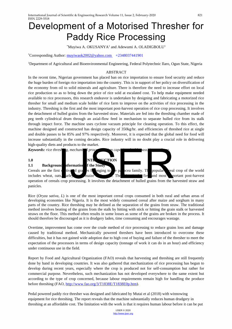
2.4 Machine Description
The thresher consists mainly of threshing drum, shaft, concave screen, threshing peg-tooth like beater, grain
chute, feed tray, belt and pulley, bearing, baffle plate, straw chute (or straw outlet), straw thrower and electric
motor/oil engine. The threshing drum carried the peg-teeth and straw throwers by welds and it was fixed to the
shaft by a flange.
The drum was enclosed in a top cover and a bottom concave screen and finally suspended on two sealed ball
bearings bolted onto the rigid frame of the thresher (see figure 6 for details). The top cover which had baffle
plates, feed tray, straw outlet was attached to the rigid structural frame of the thresher with bolts and nuts. The
concave screen was firmly attached to the rigid structural frame by welds. An electric motor and belt drive were
used to connect the shaft carrying the threshing drum to the drive shaft through pulleys. The electric motor
provided the primary motion that transmits torque through the pulleys.
The suction blower is located just under the hopper and opposite the slope of the tray. It is a centrifugal fan and
is comprised of four straight impellers attached to the shaft, all in an involute casing. A pulley is attached to the
shaft at one of the ends.
Figure 4 below is the pictorial view of the rice thresher. Member frame is made from stainless steel of 2mm
thickness while the support is made from angle iron of 40 x 40 x 5mm dimension. Stainless steel was considered
for construction of parts since the machine is to be used to process edible crop. Some of the major components
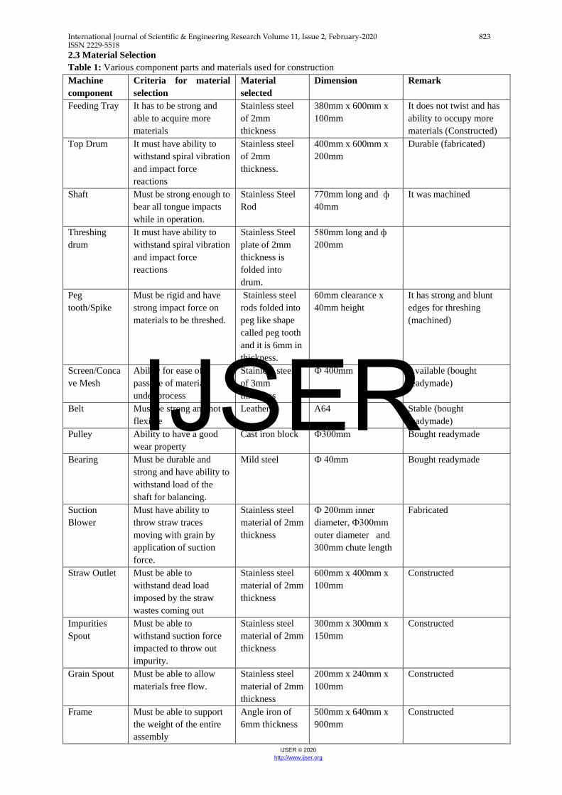
are as shown in figures 2, 3, 4, 5, 6 and 7 below. Figure 5 shows the threshing drum, transmission shaft and the
drive that transmits power from the prime mover. The shaft diameter was estimated as 23mm (see design
calculations below for details).
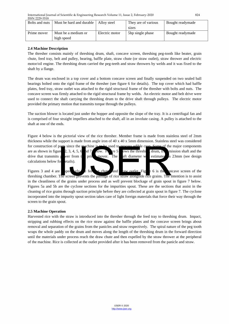
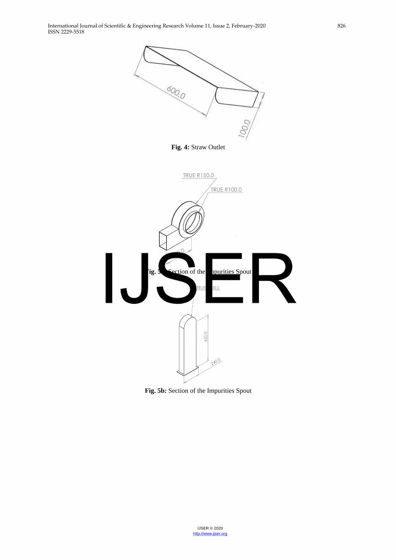
Figures 3 and 4 are respectively the feeding chutes and straw outlet. Figure 6 is the concave screen of the
threshing chamber. The screen prevents the passage of rice straw alongside rice grains. The intention is to assist
in the cleanliness of the grains under process and as well prevent blockage of grain spout in figure 7 below.
Figures 5a and 5b are the cyclone sections for the impurities spout. These are the sections that assist in the
cleaning of rice grains through suction principle before they are collected at grain spout in figure 7. The cyclone
incorporated into the impurity spout section takes care of light foreign materials that force their way through the
screen to the grain spout.
2.5 Machine Operation
Harvested rice with the straw is introduced into the thresher through the feed tray to threshing drum. Impact,
stripping and rubbing effects on the rice straw against the baffle plates and the concave screen brings about
removal and separation of the grains from the panicles and straw respectively. The spiral nature of the peg tooth
wraps the whole paddy on the drum and moves along the length of the threshing drum in the forward direction
until the materials under process reach the draw chute and then expelled by the straw thrower at the peripheral
of the machine. Rice is collected at the outlet provided after it has been removed from the panicle and straw.
IJSER
International Journal of Scientific & Engineering Research Volume 11, Issue 2, February-2020 825 ISSN 2229-5518
IJSER © 2020
http://www.ijser.org
Fig. 1: Pictorial View of the Rice Thresher
Fig. 2: Threshing Drum
Fig. 3: Feeding chute
IJSER
International Journal of Scientific & Engineering Research Volume 11, Issue 2, February-2020 826 ISSN 2229-5518
IJSER © 2020
http://www.ijser.org
Fig. 4: Straw Outlet
Fig. 5a: Section of the Impurities Spout
Fig. 5b: Section of the Impurities Spout
IJSER

International Journal of Scientific & Engineering Research Volume 11, Issue 2, February-2020 827 ISSN 2229-5518
IJSER © 2020
http://www.ijser.org
Fig. 6: Concave Screen of the Threshing Chamber
Fig. 7 Clean Grain Spout
2.6 Procedure for Rice Threshing
Harvested crop is loaded onto the tray and fed into the opening between the cylinder and the concave screen at
one end of the machine. The pegs on the threshing cylinder hit the material separating the grain from the straw,
and at the same time accelerating them around the cylinder.
Majority of the grain is threshed during initial impact but further threshing is performed as the material moves
axially until the straw is discharged at the opposite end. Threshed grain, including impurities such as leaves and
short pieces of straw, pass through the openings in the concave screen and in some cases fall on an oscillating
screen (separated from the entire assembly) where large impurities are separated.
2.7 Materials for Evaluation
Materials used for the machine evaluation are un-threshed rice, sensitive measuring scale, stop watch and
recording materials. The only variable considered during the evaluation exercise was time it took to thresh the
rice.
2.8 Statistical Methods for Data Analysis
Results from the evaluation work were presented in tables and charts. Parameters considered during evaluation
work are threshing efficiencies based on number of pass, throughput capacity or tonnage of work it can do in an
hour, etc.
2.9 Design Calculations
2.9.1 Input power measurement
IJSER

International Journal of Scientific & Engineering Research Volume 11, Issue 2, February-2020 828 ISSN 2229-5518
IJSER © 2020
http://www.ijser.org
The input power measurement can be determined from the name plate information of the prime mover used to
power the machine. It can also be determined from the drive for the transmission shaft of the machine. In this
endeavor, the input power for the thresher was calculated from the belt drive used for power transmission.
𝑷 = {𝑻𝟏 − 𝑻𝟐}𝒙 𝒗 (𝑾𝒂𝒕𝒕𝒔) …………………….……………………….(1) (Hall etal, 1973)
T1 = belt tension in tight side (N)
T2 = belt tension in loose side (N)
V = belt speed, m/s
V = wr, where w = angular speed and r = radius of shaft or pulley under consideration.
In finding the required power, equations 2, 3and 4 below are needed.
{𝑻𝟏 − 𝒎𝒗𝟐}/{𝑻𝟐 − 𝒎𝒗𝟐} = 𝒆^{𝒇𝜶/ 𝐬𝐢𝐧𝟏
𝟐Ɵ } ………………………....(2) (Hall etal, 1973)
𝝆 = density of belt = 970 kg/m3 for leather belt
𝜃 = 1800 or 𝜋 for flat belt, b = width of belt, t = thickness of belt
m = mass in kilogram
Load Carrying Capacity
Load carry capacity is calculated for pulley with lower 𝒆^{𝒇𝜶
𝐬𝐢𝐧𝟏
𝟐Ɵ
} value
For the rice thresher, the following parameters were taken from the design:
C = 560mm, ∅1 = 170mm, ∅2 = 25.1mm, b = 10.6mm, t = 5.4mm
C = shaft center distance, ∅1 = 𝑡𝑟𝑎𝑛𝑠𝑚𝑖𝑠𝑠𝑖𝑜𝑛 𝑠ℎ𝑎𝑓𝑡 𝑝𝑢𝑙𝑙𝑒𝑦, ∅2 = 𝑀𝑜𝑡𝑜𝑟 𝑠ℎ𝑎𝑓𝑡 𝑝𝑢𝑙𝑙𝑦
𝒎 = 𝝆𝒃𝒕 …………………………………………………………………………..(3) (Hall etal, 1973)
𝑚 = 970 𝑥 10.6 𝑥 5.4/{1000 𝑥 100}
m = 0.056 kg/m
𝑵𝟏𝑫𝟏 = 𝑵𝟐𝑫𝟐 ………………………………………………………………………..………..…(4)
Where N1 = prime mover speed, D1 = Diameter of pulley on prime mover shaft.
N2 = Transmission shaft speed, D2 = Diameter of pulley on transmission shaft.
N1 = 1450rpm (from name plate of prime mover), N2 = ? D1 = 25.1mm, D2 = 170mm
From equation 4, Transmission shaft speed, N2 = 214.1rpm
𝑣 =𝜋𝐷𝑁
60=
{𝜋 𝑥 170 𝑥 214.1}
{60 𝑥 1000}
= 1.91 m/s
𝑻𝟏 = 𝒃𝒕𝒔 …………………………………………………………………………(5) (Hall etal, 1973)
Where s = maximum allowable stress = 2Mpa for flat belt
From equation 5,
𝑻𝟏 = 𝒃𝒕𝒔 = 𝟏𝟎.𝟔
𝟏𝟎𝟎𝟎𝒙 𝟓.
𝟒
𝟏𝟎𝟎𝟎𝒙 𝟐 𝒙 𝟏𝟎𝟔
= 114.48N
Angle of Rap (𝜶)
If f is assumed to be 0.3, where f = coefficient of friction between belt and pulley
𝛼1 = 180 − 2𝛽,
𝛼2 = 180 + 2𝛽 , c where 𝛽 = 𝐬𝐢𝐧 ̂ {−𝟏{𝑹−𝒓}
𝑪}
Where 𝛼1 and 𝛼2 are angle of rap for tight and slack side of belt dive.
𝜶𝟏 = 𝟏𝟖𝟎 − 𝟐𝐬𝐢𝐧 ̂ {−𝟏{𝑹−𝒓}
𝑪} …………………………………………………………..……..(6)
𝜶𝟐 = 𝟏𝟖𝟎 + 𝟐𝐬𝐢𝐧 ̂ {−𝟏{𝑹−𝒓}
𝑪} ………………………………………………………..……..... (7)
𝜶𝟏 = 𝟏𝟖𝟎 − 𝟐𝐬𝐢𝐧 ̂ {−𝟏{
𝟏𝟕𝟎
𝟐−𝟐𝟓.
𝟏
𝟐}
𝟓𝟔𝟎}
= 180 – 2 x 7.34
𝜶𝟏 = 165.130
From the formula in equation 7, 𝜶𝟐 = 𝟏𝟗𝟒. 𝟖𝟔0
From equation 2, 𝒆^{𝒇𝜶
𝐬𝐢𝐧𝟏
𝟐Ɵ
} = 2.375 for 165.130
Also 𝒆^{𝒇𝜶
𝐬𝐢𝐧𝟏
𝟐Ɵ
} = 2.34 for 194.860
Hence, bigger pulley governs.
From equation 2 again,
{𝑻𝟏 − 𝒎𝒗𝟐}/{𝑻𝟐 − 𝒎𝒗𝟐} = 𝒆^{𝒇𝜶/ 𝐬𝐢𝐧𝟏
𝟐Ɵ }
IJSER
International Journal of Scientific & Engineering Research Volume 11, Issue 2, February-2020 829 ISSN 2229-5518
IJSER © 2020
http://www.ijser.org
700mm
Therefore,
{𝟏𝟏𝟒.𝟒𝟖−𝟎.𝟎𝟓𝟔 𝒙 𝟏.𝟗𝟏𝟐}
{𝑻𝟐− 𝟎.𝟎𝟓𝟔 𝒙 𝟏.𝟗𝟏𝟐}= 𝟐. 𝟑𝟒 , making T2 the subject,
T2 = 49.04 N
Power requirement
From equation 1, power requirement is as calculated below:
𝑷 = {𝑻𝟏 − 𝑻𝟐}𝒙 𝒗
𝑣 =𝜋𝐷𝑁
60 = 1.91 m/s
𝑃 = {114.48 − 49.04}𝑥 1.91
= 124.99 W
≈ 125W
2.9.2 Torque Requirement
𝑻𝒐𝒓𝒒𝒖𝒆 = (𝑻𝟏 − 𝑻𝟐)𝑹 ……………………………………………………………….(8) (Hall etal, 1973)
R = Radius of bigger pulley
𝑇𝑜𝑟𝑞𝑢𝑒 = (114.48 − 49.04) 𝑥85
1000
= 5.56 Nm
2.9.3 Shear force and bending moment calculation
W1 = weight of main shaft carrying threshing drum = 120N
W2 = weight of materials to be processed at right half side of the threshing chamber = 32N
W3 = weight of materials to be processed at left half side of the threshing chamber = 32N
W4 = weight of pulley = 20N
R1 = reaction from bearing at left side
R2 = reaction from bearing at right side
S.F. = shear force
B.D. = bending moment
Shear force calculation
SF: 𝑹𝟏 + 𝑹𝟐 = 𝒘𝟏 + 𝒘𝟐 + 𝒘𝟑 + 𝒘𝟒 (upward force = downward force) ………….…..…. (9)
𝑅1 + 𝑅2 = 20 + 32 + 120 + 32
= 204N
B.M.: Taking moment about R1
𝚺𝑩𝑴 = 𝟎 ………………………………………………………………………….…………… (10)
Σ𝐵𝑀 = −𝑤4 𝑥 0.1 + 𝑤2 𝑥 0.175 + 𝑤1 𝑥 0.35 + 𝑤3 𝑥 0.525 − 𝑅2 𝑥 0.7 = 0
From there, R2 = 89.14N
Note that R1 + R2 = 204N
Then R1 = 204 – 89.14 = 114.86N
Bending moment calculation
1. At point A: BM = -20 x 0.8 = -16Nm
2. At point B: BM = -16 + R1 x 0.7 = 64.5Nm
3. At point C: BM = -16 + 80.5 – w2 x 0.525 = 47.7Nm
4. At point D: BM = -16 + 80.5 – 16.8 – w1 x 0.35 = 5.7Nm
5. At point E: BM = 5.7 – w3 x 0.175 = 0.1 ≈0.0Nm
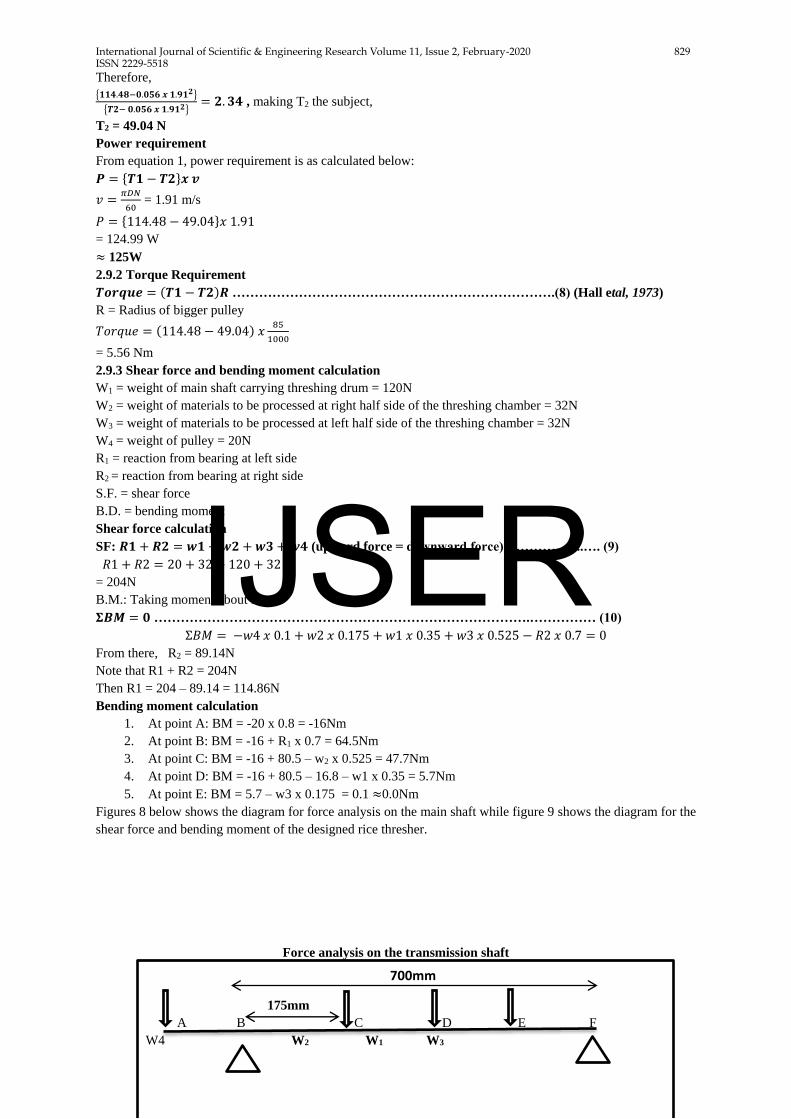
Figures 8 below shows the diagram for force analysis on the main shaft while figure 9 shows the diagram for the
shear force and bending moment of the designed rice thresher.
Force analysis on the transmission shaft
175mm
A B C D E F
W4 W2 W1 W3
IJSER

International Journal of Scientific & Engineering Research Volume 11, Issue 2, February-2020 830 ISSN 2229-5518
IJSER © 2020
http://www.ijser.org
100mm 175mm
R1 R2
350mm
Fig 8: Diagram on force analysis on the transmission shaft
Fig 9: Diagram of Shear Force and Bending Moment
2.9.4 Transmission shaft design
Shaft design consists primarily of the determination of the correct shaft diameter to ensure satisfactory strength
and rigidity when the shaft is transmitting power under various operating and loading conditions. Shafts are
usually in cross-section, and may be either hollow or solid. The shaft considered for design in this technical
report is solid shaft.
The ASME code equation for solid shaft diameter is as given in equation in equation 10 below.
𝒅𝟑 =𝟏𝟔
𝝅𝑺𝒔√{(𝒌𝒃𝑴𝒃)𝟐 + (𝑲𝒕𝑴𝒕)𝟐} ……………………………………… (10) (Hall etal, 1973)
Mb = bending moment
Mt = Torsional Moment
Kb = combined torque and fatigue factor applied to bending moment
Kt = combined torque and fatigue factor applied to torsional moment
From ASME code, Ss = 40MN/m2 for shaft with key
Also, Kb = 1.5, Kt = 1.0
From the bending moment calculation above, Mb = 64.5Nm
Also,
𝑴𝒕 = {𝑻𝟏 − 𝑻𝟐} 𝒙 𝑹 (𝑵𝒎) …………………………………………………...(11)
95N
63N
SF
- 20N - 57N
64.5Nm - 89N
47.7Nm
5.7Nm
BM 0Nm
-16Nm
IJSER
International Journal of Scientific & Engineering Research Volume 11, Issue 2, February-2020 831 ISSN 2229-5518
IJSER © 2020
http://www.ijser.org
𝑀𝑡 = (114.48 − 49.04)𝑥 0.17 = 11.13𝑁𝑚
𝑑3 =16
𝜋 𝑥 40 𝑥 10^6√{(1.5𝑥 64.5)2 + (1 𝑥 11.13)2}
d = 2.32 x 10⁻² m
d = 23.2mm
2.9.5 Shaft design for torsional rigidity
Rigidity is based on the permissible angle of twist. The amount of twist permissible depends on the particular
application, and varies about 0.30 / m for machine tool shafts to about 30 / m
for line shafting.
According to SAME on solid circular shaft,
𝜽 = 𝟓𝟖𝟒𝑴𝒕𝑳/𝑮𝒅𝟒 ……………………………………………………………… (12)
𝜽 = angle of twist (degree)
L = length of shaft (m) = 800mm - designed
Mt =torsional moment (Nm) = 11.13 Nm - calculated
G = torsional modulus of elasticity (Nm2) = 80 x 109 Nm2 - standard
d = shaft diameter = 23.2mm - calculated
𝜽 = 𝟓𝟖𝟒 𝒙 𝟏𝟏. 𝟏𝟑 𝒙 𝟎.𝟖
{𝟖𝟎 𝒙 𝟏𝟎𝟗𝒙 𝟐𝟑.𝟐𝟒 𝒙 𝟏𝟎−𝟏𝟐}
𝜽 = 0.2280
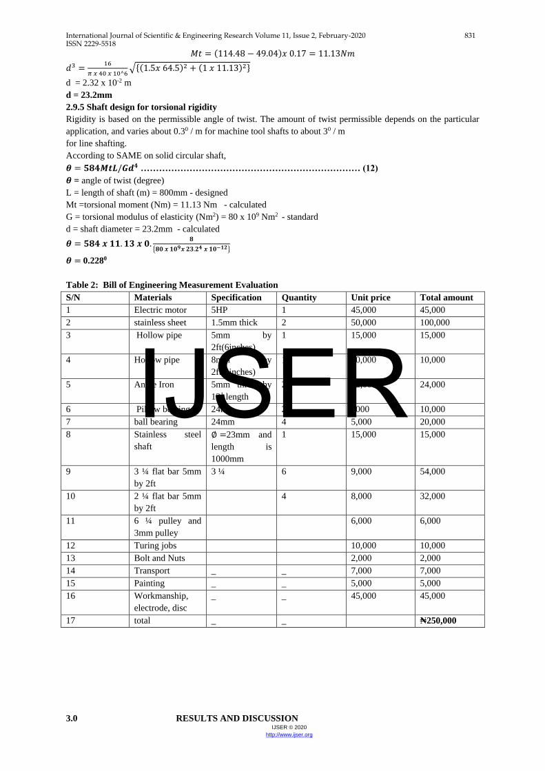
Table 2: Bill of Engineering Measurement Evaluation
S/N Materials Specification Quantity Unit price Total amount
1 Electric motor 5HP 1 45,000 45,000
2 stainless sheet 1.5mm thick 2 50,000 100,000
3 Hollow pipe 5mm by
2ft(6inches)
1 15,000 15,000
4 Hollow pipe 8mm by
2ft(4inches)
1 10,000 10,000
5 Angle Iron 5mm thick by
121 length
2 12,000 24,000
6 Pillow bearing 24mm 2 5000 10,000
7 ball bearing 24mm 4 5,000 20,000
8 Stainless steel
shaft
∅ =23mm and
length is
1000mm
1 15,000 15,000
9 3 ¼ flat bar 5mm
by 2ft
3 ¼ 6 9,000 54,000
10 2 ¼ flat bar 5mm
by 2ft
4 8,000 32,000
11 6 ¼ pulley and
3mm pulley
6,000 6,000
12 Turing jobs 10,000 10,000
13 Bolt and Nuts 2,000 2,000
14 Transport _ _ 7,000 7,000
15 Painting _ _ 5,000 5,000
16 Workmanship,
electrode, disc
_ _ 45,000 45,000
17 total _ _ ₦250,000
3.0 RESULTS AND DISCUSSION
IJSER
International Journal of Scientific & Engineering Research Volume 11, Issue 2, February-2020 832 ISSN 2229-5518
IJSER © 2020
http://www.ijser.org
3.1 Results
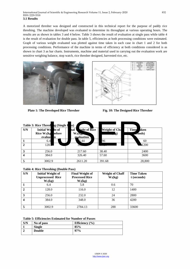
A motorized thresher was designed and constructed in this technical report for the purpose of paddy rice
threshing. The machine developed was evaluated to determine its throughput at various operating hours. The
results are as shown in tables 3 and 4 below. Table 3 shows the result of evaluation at single pass while table 4
is the result of evaluation for double pass. In table 5, efficiencies at both processing conditions were estimated.
Graph of various weight evaluated was plotted against time taken in each case in chart 1 and 2 for both
processing conditions. Performance of the machine in terms of efficiency at both conditions considered is as
shown in chart 3 as bar charts. Instruments, machine and material used in carrying out the evaluation work are
sensitive weighing balance, stop watch, rice thresher designed, harvested rice, etc.
Plate 1: The Developed Rice Thresher Fig. 10: The Designed Rice Thresher
Table 3: Rice Threshing (Single Pass)
S/N Initial Weight of
Rice W1(kg) before
evaluation
Final Weight of Rice
W2(kg) after
evaluation
Weight of Chaff
W3(kg)
Time Taken
t (seconds)
1 6.4 5.44 0.96 60
2 128.0 108.80 19.20 1200
3 256.0 217.60 38.40 2400
4 384.0 326.40 57.60 3600
5 3002.9 2611.20 391.68 28,800
Table 4: Rice Threshing (Double Pass)
S/N Initial Weight of
Unprocessed Rice
W1(kg)
Final Weight of
Processed Rice
W2(kg)
Weight of Chaff
W3(kg)
Time Taken
t (seconds)
1 6.4 5.8 0.6 70
2 128.0 116.0 12 1400
3 256.0 232.0 24 2800
4 384.0 348.0 36 4200
5 3002.9 2784.13 288 33600
Table 5: Efficiencies Estimated for Number of Passes
S/N No of pass Efficiency (%)
1 Single 85%
2 Double 97%
IJSER
International Journal of Scientific & Engineering Research Volume 11, Issue 2, February-2020 833 ISSN 2229-5518
IJSER © 2020
http://www.ijser.org
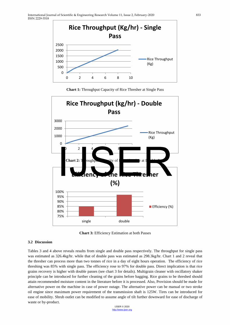
Chart 1: Throughput Capacity of Rice Thresher at Single Pass
Chart 2: Throughput Capacity of Rice Thresher at Double Pass
Chart 3: Efficiency Estimation at both Passes
3.2 Discussion
Tables 3 and 4 above reveals results from single and double pass respectively. The throughput for single pass
was estimated as 326.4kg/hr. while that of double pass was estimated as 298.3kg/hr. Chart 1 and 2 reveal that
the thresher can process more than two tonnes of rice in a day of eight hours operation. The efficiency of rice
threshing was 85% with single pass. The efficiency rose to 97% for double pass. Direct implication is that rice
grains recovery is higher with double passes (see chart 3 for details). Multigrain cleaner with oscillatory shaker
principle can be introduced for further cleaning of the grains before bagging. Rice grains to be threshed should
attain recommended moisture content in the literature before it is processed. Also, Provision should be made for
alternative power on the machine in case of power outage. The alternative power can be manual or two stroke
oil engine since maximum power requirement of the transmission shaft is 125W. Tires can be introduced for
ease of mobility. Shrub outlet can be modified to assume angle of tilt further downward for ease of discharge of
waste or by-product.
0
500
1000
1500
2000
2500
0 2 4 6 8 10
Rice Throughput (Kg/hr) - Single Pass
Rice Throughput(Kg)
0
1000
2000
3000
0 2 4 6 8 10
Rice Throughput (kg/hr) - Double Pass
Rice Throughput(Kg)
75%
80%
85%
90%
95%
100%
single double
Efficiency of the Rice Thresher (%)
Efficiency (%)
IJSER
International Journal of Scientific & Engineering Research Volume 11, Issue 2, February-2020 834 ISSN 2229-5518
IJSER © 2020
http://www.ijser.org
4.0 CONCLUSIONS AND RECOMMENDATIONS
4.1 Conclusions
A motorized thresher was designed and constructed in this technical report for the purpose of rice threshing.
Evaluation work was carried out on the machine to determine its performance in terms of throughput capacity
and efficiency at certain processing conditions.
In carrying out the evaluation work, harvested rice with the straw was introduced into the thresher through the
feed tray to the threshing drum. Impact, stripping and rubbing effects on the rice straw against the threshing
drum brings about removal and separation of the grains from the straw. The spiral nature of the spikes and the
peg tooth wraps the whole paddy on the drum and moves along the length of the threshing drum in the forward
direction until the unwanted straws and shrubs reach the draw chute and then expelled by the straw thrower at
the peripheral of the machine. Rice is collected at the sprout provided after it has been separated from the straw
and debris through suction cyclone positioned around the grain sprout.
Based on results from the evaluation work, the following conclusions were made on the rice thresher:
i. The machine throughputs for both single and double passes are respectively 326.4kg/hr. and 298.3
kg/hr.
ii. The efficiency of the machine with single pass is 85% - certain quantities of rice grains are lost
alongside bye product (chaff) in the process.
iii. With double pass, machine efficiency rose to 97%.
iv. The capacity of the machine in a day of 8 hours operation for both processing conditions is above
2 tonnes.
v. Rice grain recovery is higher with double pass.
vi. Power requirement of the transmission shaft is 125W
vii. Transmission shaft diameter is 23mm
4.2 Recommendations
The following recommendations therefore made for process optimization:
i. Multigrain cleaner with oscillatory shaker principle is recommended for further cleaning of the
grain.
ii. Rice grains to be threshed should attain recommended moisture content in the literature before it is
processed.
iii. Provision should be made for alternative power on the machine in case of power outage. The
alternative power can be manual or two stroke oil engine since maximum power requirement of
the transmission shaft is 125W.
iv. Tires should be introduced for ease of mobility.
v. Shrub outlet should be modified to assume angle of tilt further downward.
REFERENCES
FAO, http://www.fao.org/3/T1838E/T1838E0p.htm Accessed October 2019.
Hall A.S., A.R. Holowenko and Laughlin H.G. (2017). Theory and Problems of Machine Design, Schaum’s
Outline Series. Tata McGraw-Hill Publishing Company Limited, New Delhi New York, 1973.
Mutai E. B. K., Ochieng M. and Swaleh M. (2018). Design and Fabrication of Pedal Powered Paddy Rice
Thresher. International Journal of Innovative Research in Engineering & Management (IJIREM). ISSN: 2350-
0557, Volume-5, Issue-6, November-2018.
Udemezue J.C. and Osegbue E.G. (2018). Analysis of Rice Production and Consumption Trends in Nigeria.
Annals of Reviews and Research, Volume 1 Issue 5, Pgs. 1-4.
IJSER

International Journal of Scientific & Engineering Research Volume 11, Issue 2, February-2020 835 ISSN 2229-5518
IJSER © 2020
http://www.ijser.org
APPENDIX I
Exploded view of the rice thresher
IJSER

International Journal of Scientific & Engineering Research Volume 11, Issue 2, February-2020 836 ISSN 2229-5518
IJSER © 2020
http://www.ijser.org
APPENDIX II
Machine Evaluation Exercise
IJSER