development of a low-cost xuan song parallel kinematic ... · department of mechanical and...
TRANSCRIPT
Xuan SongDaniel J. Epstein Department of Industrial
and Systems Engineering,
University of Southern California,
Los Angeles, CA 90089
Yayue PanDepartment of Mechanical
and Industrial Engineering,
University of Illinois at Chicago,
Chicago, IL 60607
Yong Chen1
Daniel J. Epstein Department of Industrial
and Systems Engineering,
University of Southern California,
Los Angeles, CA 90089
e-mail: [email protected]
Development of a Low-CostParallel Kinematic Machinefor Multidirectional AdditiveManufacturingMost additive manufacturing (AM) processes are layer-based with three linear motionsin the X, Y, and Z axes. However, there are drawbacks associated with such limitedmotions, e.g., nonconformal material properties, stair-stepping effect, and limitations onbuilding-around-inserts. Such drawbacks will limit AM to be used in more general appli-cations. To enable 6-axis motions between a tool and a work piece, we investigated aStewart mechanism and the feasibility of developing a low-cost 3D printer for the multi-directional fused deposition modeling (FDM) process. The technical challenges in devel-oping such an AM system are discussed including the hardware design, motion planningand modeling, platform constraint checking, tool motion simulation, and platform cali-bration. Several test cases are performed to illustrate the capability of the developed mul-tidirectional AM system. A discussion of future development on multidirectional AMsystems is also given. [DOI: 10.1115/1.4028897]
Keywords: additive manufacturing, multidirection, parallel kinematic machine, fuseddeposition modeling, building-around-inserts
1 Introduction
AM processes can directly fabricate three-dimensional (3D)computer-aided design (CAD) models by controlling the selectiveaccumulation of materials. Most AM processes are layer-based,that is, a given 3D model is first sliced into a set of two-dimensional (2D) layers; accordingly, a physical part is fabricatedby stacking the sliced 2D layers together to approximate the givenCAD model. An example of a tilted rod (AB) using the layer-based AM processes is shown in Fig. 1. For such AM processes,only the linear motions in the X, Y, and Z axes are required.
The layer-based fabrication approach has many benefits. Forexample, (1) tool path planning and hardware design are simpli-fied; and (2) complex shapes that are impossible to be madebefore can be fabricated. However, there are also drawbacks asso-ciated with the layer-based fabrication approach. For example, (1)the surface finish is poor due to the stair-stepping effect (refer torod AB in Fig. 1); (2) the material property of a geometric featurewill depend on the building direction used in the fabrication pro-cess. Consequently, the material property of a tilted rod in differ-ent tilting angles will be different. In addition, (3) it would bedifficult to build parts around inserts (e.g., embedding electric oroptical components) due to the limited tool motions that areallowed in the system.
To address the problems of the layer-based AM processes, vari-ous methods have been proposed. For example, controlled curedepth [1,2], postprocessing [3,4] and meniscus methods [5,6] havebeen developed for improving surface finish; and techniques suchas model shape modification [7] and hybrid process development[8] have been employed to enhance the fabrication capability ofbuilding-around-inserts. However, most approaches can onlyimprove one or a few drawbacks in a limited fashion mainly dueto the use of a single build direction (Z axis) and a uniform layer
thickness in the building process. In comparison, multidirectionalAM processes, in which materials are added along multiple direc-tions using nonuniform layer thickness, can address many limita-tions of the layer-based AM processes. We believe both layer-based and nonlayer-based material deposition approaches will beemployed in future AM processes.
To achieve multi-axis motions between accumulative tools anda workpiece, multidirectional AM processes can be classified into(1) platform based and (2) accumulative tool based approaches.
(1) Platform based approaches. Multidirectional fabricationcan be achieved by rotating the platform in order to orien-tate the workpiece related to the accumulative tool. Forexample, a customized compliant parallel kinematicmachine is presented in Ref. [9] for the multidirection lay-ered deposition process. The machine is comprised of twoparts: an X-Y overhang head unit, and a workpiece orienta-tion unit to rotate the built part to have a building directionthat is aligned to the head unit. Consequently, the deposi-tion head can add materials from different orientations. Thelaser direct casting process [10] uses a similar approach byrotating built parts to achieve multidirectional fabrication.A multidirectional UV lithography process at micro- andnanoscales is discussed in Ref. [11], in which two stepmotors are used to control the tilting and rotational anglesof the substrate. In the design of a laser direct metal deposi-tion (DMD) system [12] for repairing deep and internalcracks in metallic components, the laser beam is kept sta-tionary while the workpiece is moved and rotated.
(2) Accumulative tool based approaches. In multidirectionalAM processes, the accumulative tools, instead of the plat-form, can be oriented with multiple degrees of freedom. Amultidirectional DMD system using a high-power laser ispresented in Refs. [13–16]. The laser beam is focused ontoa workpiece and produces a melting pool. Medal powdersare injected into the melting pool by feeding with inert gasstream. In the system, the laser head is controlled by a 5-axis motion mechanism that allows deposition of givenshapes. As shown in Ref. [16], the slicing direction can be
1Corresponding author.Contributed by the Manufacturing Engineering Division of ASME for publication
in the JOURNAL OF MANUFACTURING SCIENCE AND ENGINEERING. Manuscript receivedApril 15, 2014; final manuscript received October 14, 2014; published onlineDecember 12, 2014. Assoc. Editor: David L. Bourell.
Journal of Manufacturing Science and Engineering APRIL 2015, Vol. 137 / 021005-1Copyright VC 2015 by ASME
Downloaded From: http://manufacturingscience.asmedigitalcollection.asme.org/ on 02/24/2015 Terms of Use: http://asme.org/terms

arbitrary, and a number of layers with nonuniform thicknessescan be generated. Accordingly, the tool path planning soft-ware can convert CAD models into nozzle motions for multi-axis deposition. The directed light fabrication process [17] isanother kind of DMD process that fuses inert-gas-deliveredmetal powders into the focal zone of a high powered laserbeam. By using the multi-axis numerical control sequencetool paths, materials can also be deposited in varying orienta-tions. For the fabrication of polymer-based objects, a com-puter numerically controlled accumulation process wasdeveloped [18], in which a fiber optical cable connected witha UV-LED (Light Emitting Diode) is controlled by a 5-axismotion system to enable the X, Y, and Z axes translations andthe A and B axes rotations. Therefore, the accumulative toolcan cure liquid resin in various directions.
Compared with the tool based approaches, the platform basedprocesses have simpler structures. However, rotating an accumu-lative tool instead of the platform is more flexible in achievingdesired relative motions. In the past few years, various low-cost3D printers (e.g., MakerBot, Solidoodle, Cube, Robox, etc.) usingthe X, Y, and Z linear motions have been developed with a pricearound $500–$2000. Some nontraditional designs to achieve thelinear motions have also been developed (e.g., RepRap Mini Kos-sel based on a delta design, refer to Fig. 2). However, at themoment, it is not clear whether a low-cost multidirectional 3Dprinter is feasible; and if so, what should be its design?
To enable 6-axis motions between a tool and a work piece, aStewart mechanism is investigated in this paper for developing alow-cost multidirectional 3D printing system. An FDM heatingextruder is considered as the accumulative tool in our study. Com-pared with the traditional translation and rotation based approach,the Stewart mechanism enables the AM system to be less bulky.
The rest of the paper is organized as follows. Section 2 introducesthe hardware design based on the Stewart mechanism. The cost ofthe prototype system is also discussed. In Sec. 3, a kinematic mod-eling and simulation software system is presented. A laser-camerasystem is also discussed to reduce the deposition gap errors. Sec-tion 4 describes a calibration method to achieve improved accu-racy of the parallel kinematic machine. Section 5 presents the dataprocessing pipeline of the multidirectional AM system based onthe machine. Section 6 demonstrates the fabrication process of theprototype multidirectional FDM system with a discussion of theexperimental results. Finally, conclusions are drawn in Sec. 7.
2 Hardware Design
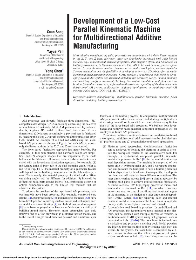
There exist many different ways of achieving multi-axis motionof the extruder. Figure 3 shows two 6-axis robotic arms of bothindustrial and desktop levels. The industrial robotic arm isextremely expensive for our application, although it is relativelyaccurate and rigid. The desktop level robotic arm is quite afford-able, but its low rigidity and accuracy cannot meet the require-ment of AM. An alternative way is to integrate multiple rotationswith the XYZ translations. However, as demonstrated in our previ-ous work [18], the machine is bulky and the process is relativelyslow. The recent development of 3D printers based on the Deltadesign (e.g., Orion Delta from SeeMeCNC and Mini Kossel fromRepRap) demonstrate that the Delta design can achieve muchfaster linear motions than the traditional design based on the X, Y,and Z linear stages. It motivates us to investigate similar designsfor multidirectional AM processes.
To enable the 6DoF motion of a tool with respect to a fixedframe, six length-changeable struts are used to connect a movingplatform on which an accumulative tool is mounted. For eachstrut, one of its ends is connected to the moving platform by a3DoF joint, and another end is connected to a fixed base frame bya 2DoF joint (refer to Fig. 3(a)). This 6-axis parallel kinematicmachine is also called Gough–Stewart mechanism. The mecha-nism has been used in precision positioning system (e.g., Hexapod6-axis parallel positioning systems from Physik Instrumente).However, the commercial systems are expensive (>$20 K) withrelatively small travel ranges (<50 mm). They are not suitable fordeveloping a low-cost multidirectional 3D printing system.
Motivated by the recent progress on developing low-cost 3Dprinters using the Delta design, we investigate the feasibility ofusing low-cost components in developing a 6-axis parallel posi-tioning system with sufficient accuracy for AM processes. It isshown, with the aid of an integrated position sensor and relatedtool path planning software systems (refer to Sec. 3), a
Fig. 1 A schematic illustration of layer-based and multidirectional AM processes
Fig. 2 Some low-cost 3D printers on market for the layer-based material deposition
021005-2 / Vol. 137, APRIL 2015 Transactions of the ASME
Downloaded From: http://manufacturingscience.asmedigitalcollection.asme.org/ on 02/24/2015 Terms of Use: http://asme.org/terms
multidirectional 3D printer with a price around $2500 is feasible.The hardware components of our parallel kinematic machine areintroduced as follows.
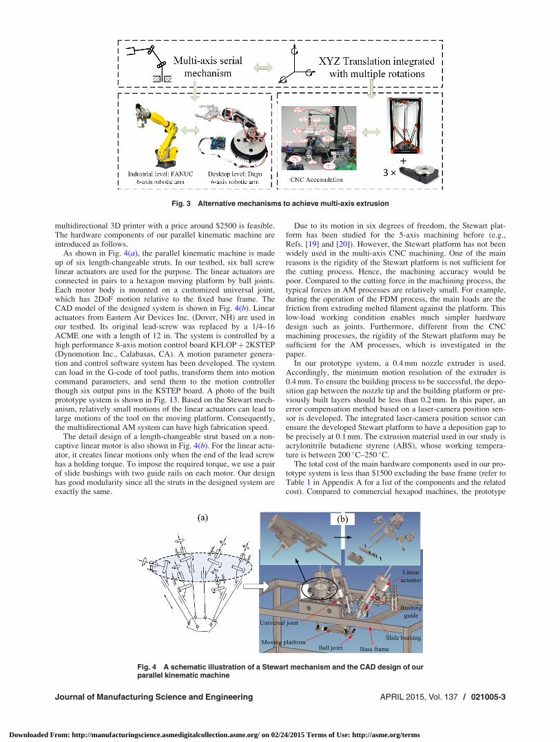
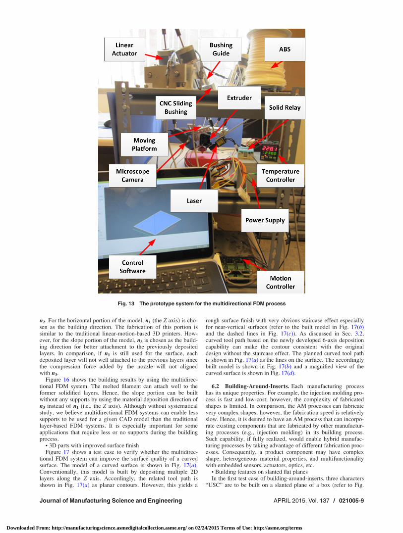
As shown in Fig. 4(a), the parallel kinematic machine is madeup of six length-changeable struts. In our testbed, six ball screwlinear actuators are used for the purpose. The linear actuators areconnected in pairs to a hexagon moving platform by ball joints.Each motor body is mounted on a customized universal joint,which has 2DoF motion relative to the fixed base frame. TheCAD model of the designed system is shown in Fig. 4(b). Linearactuators from Eastern Air Devices Inc. (Dover, NH) are used inour testbed. Its original lead-screw was replaced by a 1/4–16ACME one with a length of 12 in. The system is controlled by ahigh performance 8-axis motion control board KFLOPþ 2KSTEP(Dynomotion Inc., Calabasas, CA). A motion parameter genera-tion and control software system has been developed. The systemcan load in the G-code of tool paths, transform them into motioncommand parameters, and send them to the motion controllerthough six output pins in the KSTEP board. A photo of the builtprototype system is shown in Fig. 13. Based on the Stewart mech-anism, relatively small motions of the linear actuators can lead tolarge motions of the tool on the moving platform. Consequently,the multidirectional AM system can have high fabrication speed.
The detail design of a length-changeable strut based on a non-captive linear motor is also shown in Fig. 4(b). For the linear actu-ator, it creates linear motions only when the end of the lead screwhas a holding torque. To impose the required torque, we use a pairof slide bushings with two guide rails on each motor. Our designhas good modularity since all the struts in the designed system areexactly the same.
Due to its motion in six degrees of freedom, the Stewart plat-form has been studied for the 5-axis machining before (e.g.,Refs. [19] and [20]). However, the Stewart platform has not beenwidely used in the multi-axis CNC machining. One of the mainreasons is the rigidity of the Stewart platform is not sufficient forthe cutting process. Hence, the machining accuracy would bepoor. Compared to the cutting force in the machining process, thetypical forces in AM processes are relatively small. For example,during the operation of the FDM process, the main loads are thefriction from extruding melted filament against the platform. Thislow-load working condition enables much simpler hardwaredesign such as joints. Furthermore, different from the CNCmachining processes, the rigidity of the Stewart platform may besufficient for the AM processes, which is investigated in thepaper.
In our prototype system, a 0.4 mm nozzle extruder is used.Accordingly, the minimum motion resolution of the extruder is0.4 mm. To ensure the building process to be successful, the depo-sition gap between the nozzle tip and the building platform or pre-viously built layers should be less than 0.2 mm. In this paper, anerror compensation method based on a laser-camera position sen-sor is developed. The integrated laser-camera position sensor canensure the developed Stewart platform to have a deposition gap tobe precisely at 0.1 mm. The extrusion material used in our study isacrylonitrile butadiene styrene (ABS), whose working tempera-ture is between 200 �C–250 �C.
The total cost of the main hardware components used in our pro-totype system is less than $1500 excluding the base frame (refer toTable 1 in Appendix A for a list of the components and the relatedcost). Compared to commercial hexapod machines, the prototype
Fig. 3 Alternative mechanisms to achieve multi-axis extrusion
Fig. 4 A schematic illustration of a Stewart mechanism and the CAD design of ourparallel kinematic machine
Journal of Manufacturing Science and Engineering APRIL 2015, Vol. 137 / 021005-3
Downloaded From: http://manufacturingscience.asmedigitalcollection.asme.org/ on 02/24/2015 Terms of Use: http://asme.org/terms

system has a much lower cost, which is critical for developing low-cost multidirectional 3D printers in the future. The Stewart-mecha-nism-based system is general. It allows accumulative tools withany 6-axis motions using various material deposition principles. Inthe paper, the FDM process is demonstrated using the developedprototype system. Other AM processes can also be used by mount-ing different accumulative tools on the platform. In addition, thesystem has low inertia with small energy consumption, since all themotions are conducted by moving accumulative tools, which aregenerally lighter than the workpiece.
3 Motion Planning and Software System Design
The desired tool motion in the 6-axis parallel kinematicmachine needs to be converted into the linear motions of the six
length-changeable struts. Accordingly, the motion controller canbe used to control the linear actuators to move required displace-ments and rotations.
3.1 System Coordinate Transformation. In the motionplanning, quaternion q is used in describing the pose of the mov-ing platform. That is, for a rotation angle h around a unit vectorðvx; vy; vzÞT, its quaternion q is described as
q ¼ ðq1; q2; q3; q4ÞT
¼ cosh2
� �; vx sin
h2
� �; vy sin
h2
� �; vz sin
h2
� �� �T
(1)
Accordingly, the rotation matrix can be obtained using quaternionelements
RðqÞ ¼q2
1 þ q22 � q2
3 � q24 2q2q3 � 2q1q4 2q2q4 þ 2q1q3
2q2q3 þ 2q1q4 q21 � q2
2 þ q23 � q2
4 2q3q4 � 2q1q2
2q2q4 � 2q1q3 2q3q4 þ 2q1q2 q21 � q2
2 � q23 þ q2
4
0B@
1CA (2)
To establish the transformation model from the given quater-nion to the absolute displacement of the six axes, two coordinatesystems are shown in Fig. 5(a). One coordinate system is attachedto the fixed base frame (B) and another one is fixed on the movingframe (P). Initially, the moving frame has the same coordinateaxes as those of the base frame (refer to OP and OB in Fig. 5(a)).During the fabrication process, the coordinate system of the mov-ing frame is aligned with the accumulation tool and will be differ-ent from the original one.
Suppose any platform pose is given as ðxoP; yoP
; zoP;qÞ. Its first
part, ðxoP; yoP
; zoPÞ is the origin position of the moving frame. The
second part, q, is the quaternion of the moving frame after therotation from its initial position. Both of them are defined in termsof the coordinate system of the base frame. Accordingly, we know
PiBi
��!B
¼ OBBi
���!B
�OBOP
���!B
� R �OPPi
���!P
(3)
where PiBi
��!B
is the vector PiBi
��!defined in the coordinate system of
the base frame B; OBBi
���!B
is the position of the universal joint Bi in
terms of the coordinate system of the base frame; OBOP
���!B
is the
position of the tool tip; OBOP
���!B
¼ðxoP; yoP
; zoPÞ; OPPi���!P
is the posi-tion of the ball joint in the moving frame; R is the rotation matrixthat is calculated by Eq. (2); and i¼ 0, 1,., 5. Consequently, thedisplacement Dli of the ith strut is
Dli ¼ PiBi
��!B��� ���� li0
where li0 is the initial joint offset.In our hardware design, the base joints are not exactly located
on the legs (refer to Fig. 5(b)). Consequently, the deviation of thelead screw from the base joint needs to be considered when com-puting the displacement. That is
Dli ¼
ffiffiffiffiffiffiffiffiffiffiffiffiffiffiffiffiffiffiffiffiffiffiffiffiffiffiffiffiffiffiffiPiBi
��!B����
����2
�dev2
s� li0 (4)
3.2 Tool Path Planning. As mentioned in Sec. 1, multidirec-tional AM could improve surface finish, optimize the directionof material deposition, and overcome the limitations in
building-around-inserts. In order to achieve these benefits, propertool paths need to be planned. The 6-axis tool motions enabled inour prototype system provide tremendously large design freedomin planning the tool paths for desired performances. For example,in order to achieve improved surface finish of a curved surface asshown in Fig. 6(a), a possible tool path is to first offset the surfaceinside by a distance n•d (d is the layer thickness and n is an offsetlayer number). A 3D offsetting algorithm can be used in comput-ing the offset CAD model [21]. The computed offset CAD modelcan then be sliced into layers based on a given building direction.The sliced layers can be fabricated using the layer-based process,during which the tool orientation is kept vertical. Finally, the dep-osition tool moves along the curved surface with the tool orienta-tion aligned with the surface normal during the building process.As shown in our experimental tests (refer to Sec. 6.1), the accord-ingly fabricated objects can achieve much better surface finish.
To build offset contours on an object surface or to build fea-tures around an inserted object, a tool path needs to be generated,e.g., starting at the point S and ending at point E (refer toFig. 6(b)). Along the tool path, the tool keeps the same orientationas the current surface normal and moves along the tangent direc-tion. Given any object, the nozzle tip will initially move to thestart point S, and then extrudes materials along the planned toolpath. Assume the tool pose at point S is (xs, ys, zs, qs). Except atthe starting point S, any other point along the path is given as itsrelative movement (Dxi, Dyi, Dzi, Dqi) with respect to its previouspoint. Therefore, the tool pose at an intermediate point I is
xs þXI
i¼Sþ1
Dxi; ys þXI
i¼Sþ1
Dyi; zs þXI
i¼Sþ1
Dzi;YSþ1
i¼I
Dqi � qs
!(5)
Then we can obtain control command for each strut using Eqs.(2)–(5). In Fig. 6, the solid circle denotes a sample position alongthe tool path, “T” represents the orientation of the tool, and thearrow is the moving direction of the tool.
3.3 Real-Time Feedback Control for Initial DepositionGap. As discussed in Sec. 3.2, the accumulation tool starts atpoint S and then moves along the tool path to the end point E. Thedeposition gap at S is critical (<0.2 mm); otherwise, the extrudedmaterials will not be able to stick to the base surface. When it hap-pens, the build will fail afterwards. Due to the low-cost
021005-4 / Vol. 137, APRIL 2015 Transactions of the ASME
Downloaded From: http://manufacturingscience.asmedigitalcollection.asme.org/ on 02/24/2015 Terms of Use: http://asme.org/terms

components used in the prototype system and the building errorsincluding the backlash in the joints, it was found that such a tighttolerance is difficult to achieve. That is, either the real gapbetween the nozzle tip and the base surface is larger than 0.2 mm,or the tip collides with the object. To address the problem, a low-cost online sensor using a laser and a camera is integrated in theprototype system. Accordingly, a control strategy for identifyingthe desired initial deposition gap is described as follows.
To avoid the undesired collision of the nozzle and the object atthe starting point, the tool tip is first moved to a point S0. Asshown in Fig. 7(a), S0 is obtained by moving the desired startingpoint S outwards along the surface normal for a certain distance.Therefore, the final tool path use in our system is segment S0Splus segment SE. Moving from S0 toward the object, the tool willstop at point S, where the deposition gap distance is within the ac-ceptance range. Then control commands for the six struts aredynamically generated and executed to move the tool along pathSE to deposit materials. Since the translations and rotations fromS0 to S are known, and all the points along the tool path are givenas relative displacements with respect to their previous points, this
initial adjustment will not influence the following motion. In addi-tion, the initial adjustment overcomes hardware errors such as thebacklash in the joints. Hence, the desired gap between the tool tipand the base surface along path SE can be ensured.
In order to identify the desired deposition gap along S0S, alaser-camera system around the tool nozzle is integrated as shownin Fig. 7(b). A red laser (Laserglow Technologies, Toronto, Can-ada) is focused toward the nozzle tip, and its laser dot is capturedby a microscope camera (Aven Inc., Ann Arbor) in real time.Since the position of the nozzle tip is fixed with respect to thecamera, only the laser dot moves in the captured image when thetool moves from S0 to S. In Fig. 7(b), the laser dot l1 is the onewhen the object surface is at the minimum allowed distance to thenozzle, and l2 is when the object surface is at the maximumallowed distance to the nozzle.
As shown in Fig. 8, the correlation between the acceptancerange of the laser dot positions in the captured images and the ac-ceptance range of the gap distance can be established. For a givencurvature of an object surface, the positions of l1 and l2 areknown. Accordingly, their pixel positions in the captured imagescan be identified, which correspond to the minimum and maxi-mum allowed gap distances, respectively. A fast image recogni-tion algorithm and an automated error compensation method canthus be developed based on the pixel positions of the laser dot inthe captured images. The tool tip will then move from S0 toward Suntil the desired deposition gap is achieved.
3.4 Workspace Evaluation. For a 6-axis motion systembased on the Stewart mechanism, not every position in the build-ing space can be accessed. The workspace is constrained by twodesign variables: strut length and joint angle. Each strut must bewithin the range bounded by the maximum and minimum rod
Fig. 5 An illustration of the coordinate systems and the mainparameters of the prototyping system
Fig. 6 Tool path planning for curve surface and build-around-inserts
Fig. 7 An illustration of initial deposition gap control. (a)Adjusted starting point for tool path and (b) a laser-camera sys-tem to achieve initial deposition gap.
Journal of Manufacturing Science and Engineering APRIL 2015, Vol. 137 / 021005-5
Downloaded From: http://manufacturingscience.asmedigitalcollection.asme.org/ on 02/24/2015 Terms of Use: http://asme.org/terms

lengths. In our testbed, the working range of each strut is (170,240) (mm). Both the base joint and platform joint have limitedrotation angles as well. They significantly influence the effectiveworking volume at a specific orientation of the tool. The con-straint ranges of the base and platform joints in our machine are(�30 deg, 45 deg) and (60 deg, 120 deg), respectively. Accord-ingly, a library of the effective workspaces for different tool orien-tations can be generated. Figure 9 shows the workspace of oursetup at two different tool orientations.
3.5 Movement Simulation and Control. A simulation soft-ware system is developed for computing the tool path based onEqs. (1)–(5). Figure 10(a) shows the graphical user interface(GUI) of the developed simulation software system using Micro-soft Visual Cþþ. A G-code file with defined quaternion at eachpoint can be opened in the viewing area. The position of each jointcan be set in the left panel. The parameters are set based on themachine calibration, which will be discussed in Sec. 4. Before thesimulation, an axis motion command file is generated from theG-code file to define the displacement of each strut based on Eqs.(3) and (4). The simulation starts only after the axis motion com-mand file passes the constraint check. After that, the originalG-code file with quaternion will be sent to the motion control soft-ware system.
Figure 10(b) shows the GUI of the developed motion controlsoftware system. The system is also developed using MicrosoftVisual Cþþ. Based on the axis motion commands generated by
the simulation system, the six linear motors will be controlledwith the defined moving positions and speeds.
4 Platform Calibration
A set of 42 parameters including OBBi
���!B
, OPPi
���!P
, and li0
(i¼ 1–6) need to be set in the coordinate transformation modelsas described in Eqs. (3) and (4). The calibration of these parame-ter values is necessary for more accurate control of the 6-axismotion. The calibration approach that is used in our system is toiteratively update the system parameters by an error model suchthat a defined cost function can be minimized based on the givenorientation and translation of the moving platform. A cost func-tion for the 6-axis platform calibration is defined in Ref. [22]. Ituses strut length measurement residual at all measured poses asthe objective function. And the calibration problem can be for-mulated as a nonlinear optimization problem, which is given asfollows:
Minimize : C¼Xn
j¼1
X6
i¼1
sij
sij ¼ ðli0 þDlijÞ2 þ dev2� ðOBBi
���!B
�OBOP
���!B
�R �OPPi
���!P
ÞT
ðOBBi
���!B
�OBOP
���!B
�R �OPPi
���!P
Þ i¼ 1;2; :::;6; j¼ 1;2; :::;n (6)
Fig. 8 Different gap distances versus pixel positions of thelaser dot in the captured images
Fig. 9 Workspaces at different tool orientations: (a) workspacewhen rotation angle is 0 deg and (b) workspace when rotating10 deg around the X axis
021005-6 / Vol. 137, APRIL 2015 Transactions of the ASME
Downloaded From: http://manufacturingscience.asmedigitalcollection.asme.org/ on 02/24/2015 Terms of Use: http://asme.org/terms

where n is the number of calibrated poses, and Dlij is the inputmoving displacement of the ith linear actuator at the jth calibratedpose of the platform.
From the kinematic equations (3) and (4), an error model canbe generated in the form
sij ¼ J � Dq (7)
where J is the Jacobian matrix, Dq ¼ ½dOBOP
���!B
dOPPi
���!P
dli�T.With the cost function and the error model, the nonlinear opti-
mization function can be solved by the Gauss–Newton Algorithm.No less than seven platform poses need to be collected in order
to calibrate the machine using Eq. (6). In our experiments, a com-puter vision based method (refer to Fig. 11) is used in measuringthe tool tip position and orientation. Two cameras are positionedorthogonal to each other. Three targets were placed on the moving
platform. Target 1 is located at the tool tip. Targets 2 and 3 weresymmetric about the X axis of the moving frame. Each camera iscalibrated such that the 3D point positions of the targets can becomputed based on the captured 2D images of both cameras. Thismeasurement approach was also used in Ref. [23]. Accordingly,the rotation matrix of the moving frame can be derived by theSVD (Singular Value Decomposition) method based on the posi-tions of the three targets. More details on the camera calibrationand 3D coordinate computation are given in Appendix B.
5 Multidirectional AM Process Overview
Based on the developed parallel kinematic machine, the majorsteps of a multidirectional AM system include: (1) tool path gen-eration, (2) system coordinate transformation, (3) platform
Fig. 10 Software systems developed for the parallel kinematic machine. (a)The simulation software system and (b) the motion control software system.
Journal of Manufacturing Science and Engineering APRIL 2015, Vol. 137 / 021005-7
Downloaded From: http://manufacturingscience.asmedigitalcollection.asme.org/ on 02/24/2015 Terms of Use: http://asme.org/terms

constraint checking, (4) movement simulation, and (5) part fabri-cation. In the tool path generation, an input CAD model is slicedin desired building orientation. The slicing direction can be deter-mined based on surface normal or feature skeleton. A sliced layercontour can be sampled into a set of discrete points. Each sam-pling point can be used to compute the positions of the six linearactuators. At each point, the tool position and orientation aregiven. As discussed in Sec. 3, the 3D coordinate of the accumula-tive tool along with its accumulation orientation is converted intoa transformation model to compute the related distances L0–L5 forthe six struts of the machine. The displacement vector can then besent to the motion controller to achieve the desired platform pose.
Note that not all the vectors computed based on the transforma-tion process can be achieved by the prototype system. Severalconstraints exist including the limitation of actuators’ stroke (i.e.,(Lmin, Lmax)), the limitation of the range of the passive joint, andthe minimum distance between each actuator’s lead screw. Hence,the computed results need to be checked using the known con-straints. The tool path can be simulated in our software system toverify whether the six-dimensional motion vectors satisfy all theconstraint equations. Finally, the verified six dimension coordi-nate vectors (L0, L1, L2, L3, L4, L5) can be sent to the controlsystem to start the building process.
Figure 12 shows the data processing pipeline of the developedmultidirectional AM system. A CNC control software system(e.g., Mach 3) may be used in converting a given CAD model intonumeric control G-codes. However, the generated G-codes haveonly the coordinate positions along which the tool tip will travel.The tool can be positioned at various orientations for a given posi-tion in the G-code. As mentioned before, one good candidate is toalign the tool orientation with the related surface normal of theobject. Algorithms for computing appropriate tool orientationsbased on multidirectional material deposition requirements needto be studied for 6-axis AM systems in the future.
6 Experimental Tests
The developed parallel kinematic machine can be used withvarious multidirectional AM processes such as the FDM processand the CNC accumulation process [18]. A photo of the developedprototype with a filament extruder of the FDM process is shownin Fig. 13. In this section, some of the performed test cases arepresented to demonstrate the capability of multidirectional FDMprocesses. A discussion of the challenges and future developmentson multi-axis AM systems is also presented. A youtube video ofthe developed prototype system and some related experimentaltests can be found at the link of Ref. [24].
6.1 Tests of Various Geometries. Different types of geome-tries are built using the developed 6-axis 3D printer to demon-strate its capability and verify some potential applications such asimproving surface finishing.
• 3D curvesThe multi-axis FDM system enables the tool to move freely in
the space. Hence, similar to 3Doodler (a handheld 3D-printingpen at kickstarter), it can be used as a 3D printing pen to accu-rately draw in the air. Figure 14 shows a test case of a spiral curve.Note the extruding orientation is constantly changed for the givencurve. The built 3D curve is also shown in Fig. 14. The shape isnot a perfect spiral because the filament is still soft after beingextruded out and slightly falls down until it gets hardened in theair.
• 3D surfacesFigure 15(a) shows the CAD model of a designed test case on
3D surfaces to be fabricated by the multidirectional 3D printer.The planned tool paths are shown in Fig. 15(b). Note that the sur-face normal of the shape changes from the vertical direction n1 to
Fig. 11 An illustration of the platform pose measurementusing two cameras
Fig. 12 Data processing pipeline of the multidirectional AM system using the par-allel kinematic machine
021005-8 / Vol. 137, APRIL 2015 Transactions of the ASME
Downloaded From: http://manufacturingscience.asmedigitalcollection.asme.org/ on 02/24/2015 Terms of Use: http://asme.org/terms
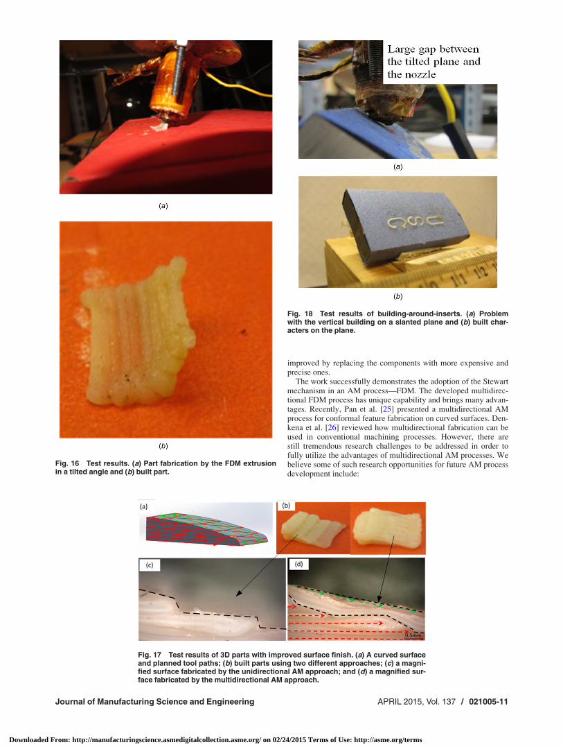
n2. For the horizontal portion of the model, n1 (the Z axis) is cho-sen as the building direction. The fabrication of this portion issimilar to the traditional linear-motion-based 3D printers. How-ever, for the slope portion of the model, n3 is chosen as the build-ing direction for better attachment to the previously depositedlayers. In comparison, if n1 is still used for the surface, eachdeposited layer will not well attached to the previous layers sincethe compression force added by the nozzle will not alignedwith n3.
Figure 16 shows the building results by using the multidirec-tional FDM system. The melted filament can attach well to theformer solidified layers. Hence, the slope portion can be builtwithout any supports by using the material deposition direction ofn3 instead of n1 (i.e., the Z axis). Although without systematicalstudy, we believe multidirectional FDM systems can enable lesssupports to be used for a given CAD model than the traditionallayer-based FDM systems. It is especially important for someapplications that require less or no supports during the buildingprocess.
• 3D parts with improved surface finishFigure 17 shows a test case to verify whether the multidirec-
tional FDM system can improve the surface quality of a curvedsurface. The model of a curved surface is shown in Fig. 17(a).Conventionally, this model is built by depositing multiple 2Dlayers along the Z axis. Accordingly, the related tool path isshown in Fig. 17(a) as planar contours. However, this yields a
rough surface finish with very obvious staircase effect especiallyfor near-vertical surfaces (refer to the built model in Fig. 17(b)and the dashed lines in Fig. 17(c)). As discussed in Sec. 3.2,curved tool path based on the newly developed 6-axis depositioncapability can make the contour consistent with the originaldesign without the staircase effect. The planned curved tool pathis shown in Fig. 17(a) as the lines on the surface. The accordinglybuilt model is shown in Fig. 17(b) and a magnified view of thecurved surface is shown in Fig. 17(d).
6.2 Building-Around-Inserts. Each manufacturing processhas its unique properties. For example, the injection molding pro-cess is fast and low-cost; however, the complexity of fabricatedshapes is limited. In comparison, the AM processes can fabricatevery complex shapes; however, the fabrication speed is relativelyslow. Hence, it is desired to have an AM process that can incorpo-rate existing components that are fabricated by other manufactur-ing processes (e.g., injection molding) in its building process.Such capability, if fully realized, would enable hybrid manufac-turing processes by taking advantage of different fabrication proc-esses. Consequently, a product component may have complexshape, heterogeneous material properties, and multifunctionalitywith embedded sensors, actuators, optics, etc.
• Building features on slanted flat planesIn the first test case of building-around-inserts, three characters
“USC” are to be built on a slanted plane of a box (refer to Fig.
Fig. 13 The prototype system for the multidirectional FDM process
Journal of Manufacturing Science and Engineering APRIL 2015, Vol. 137 / 021005-9
Downloaded From: http://manufacturingscience.asmedigitalcollection.asme.org/ on 02/24/2015 Terms of Use: http://asme.org/terms

18(a)). In the linear-motion-based FDM machines, a nozzle canonly extrude filaments vertically. Hence, it would be difficult tobuild features on such a surface since a large gap will existbetween the slanted plane and the vertical nozzle in order to avoidthe collision between them. In comparison, a desired gap distancecan be achieved by rotating the nozzle to be perpendicular to theplane. Accordingly, the characters can be fabricated on the slantedplane, which are shown in Fig. 18(b).
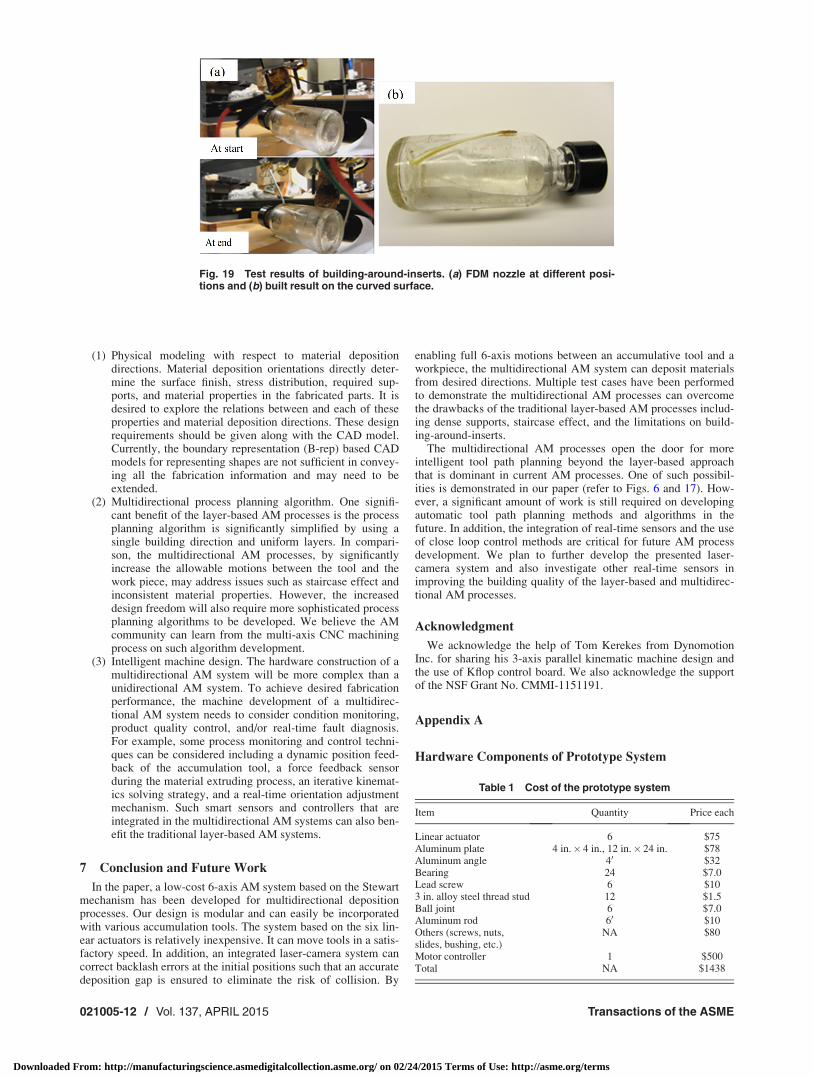
• Building features on freeform surfacesIn another test case of building-around-inserts, a curved line
needs to be deposited on the surface of a bottle that is made byanother manufacturing process. This demonstrates the capabilityof multi-axis AM process on building arbitrary shapes on an exist-ing object. As shown in Fig. 19, the bottle body is a cylinder witha diameter of �31 mm. In order to build a curved line along itssurface, the nozzle direction needs to be constantly changed inorder to keep the tool with a building direction that is coaxial withthe surface normal. The nozzle orientations at the start and endpositions are shown Fig. 19(a). The angles of the nozzle willchange from �20 deg to þ20 deg during the building process. Fig-ure 19(b) shows the fabricated result. By this method, we couldfreely add new features to an existing object or repair any portionthat has been broken. In our previous work [23], a 3D scanner wasintegrated in a CNC accumulation system such that an insertedobject can be scanned and the related tool path can be automati-cally generated based on the 3D scanning results.
6.3 Discussion. The purpose of the work is to investigate theconstruction of a low-cost multidirectional AM system and todemonstrate the unique benefits and challenges of multidirectionalAM systems. The Stewart mechanism and the process planningfor the parallel kinematic based AM machine are presented. To
demonstrate the feasibility, a simple design of an extrusion nozzleis used with ABS filament as the raw material. The achieveddesign serves as a rapid prototyping example of a successful low-cost and fully operational multidirectional AM system for futureresearchers and developers. The specifications of our multidirec-tional AM machine are given as follows.
(1) Working volume. The working volume of our system isdesigned as 100 mm� 100 mm� 100 mm. The workingvolume based on the Stewart mechanism depends on thetravel range of the lead screws and slide bushings, as wellas the angle range of the ball joints.
(2) Rotation angle of the platform. The rotation angle of themoving frame in our prototype system is 630 deg. Like theworking volume, the rotation range mainly depends on theselected ball joints, and the ravel ranges of lead screws andslide bushings.
(3) Accuracy. The accuracy of the prototype systemis< 0.5 mm. The larger the tool angle is, the lower the ac-curacy will be. It is mainly due to the errors in the universaland ball joints. However, using the laser-camera feedbackcontrol method (refer to Sec. 3.3), the deposition gap canachieve a much smaller value (0.1 mm–0.2 mm).
The constructed prototype system was intentionally built out oflow-cost components in order to verify the feasibility of multidir-ectional 3D printers in desired price range. There are variousimprovements the can be incorporated in the system, e.g., a betterextrusion nozzle and a more compact frame design. In addition,the speed, precision, and orientation capacity of system can all be
Fig. 14 A 3D spiral curve drawn by the multi-axis FDM systemFig. 15 A model with a slanted surface to be built. (a) Differentsurface normals and related building directions and (b) plannedtool path for the 3D surfaces.
021005-10 / Vol. 137, APRIL 2015 Transactions of the ASME
Downloaded From: http://manufacturingscience.asmedigitalcollection.asme.org/ on 02/24/2015 Terms of Use: http://asme.org/terms
improved by replacing the components with more expensive andprecise ones.
The work successfully demonstrates the adoption of the Stewartmechanism in an AM process—FDM. The developed multidirec-tional FDM process has unique capability and brings many advan-tages. Recently, Pan et al. [25] presented a multidirectional AMprocess for conformal feature fabrication on curved surfaces. Den-kena et al. [26] reviewed how multidirectional fabrication can beused in conventional machining processes. However, there arestill tremendous research challenges to be addressed in order tofully utilize the advantages of multidirectional AM processes. Webelieve some of such research opportunities for future AM processdevelopment include:
Fig. 16 Test results. (a) Part fabrication by the FDM extrusionin a tilted angle and (b) built part.
Fig. 17 Test results of 3D parts with improved surface finish. (a) A curved surfaceand planned tool paths; (b) built parts using two different approaches; (c) a magni-fied surface fabricated by the unidirectional AM approach; and (d) a magnified sur-face fabricated by the multidirectional AM approach.
Fig. 18 Test results of building-around-inserts. (a) Problemwith the vertical building on a slanted plane and (b) built char-acters on the plane.
Journal of Manufacturing Science and Engineering APRIL 2015, Vol. 137 / 021005-11
Downloaded From: http://manufacturingscience.asmedigitalcollection.asme.org/ on 02/24/2015 Terms of Use: http://asme.org/terms
(1) Physical modeling with respect to material depositiondirections. Material deposition orientations directly deter-mine the surface finish, stress distribution, required sup-ports, and material properties in the fabricated parts. It isdesired to explore the relations between and each of theseproperties and material deposition directions. These designrequirements should be given along with the CAD model.Currently, the boundary representation (B-rep) based CADmodels for representing shapes are not sufficient in convey-ing all the fabrication information and may need to beextended.
(2) Multidirectional process planning algorithm. One signifi-cant benefit of the layer-based AM processes is the processplanning algorithm is significantly simplified by using asingle building direction and uniform layers. In compari-son, the multidirectional AM processes, by significantlyincrease the allowable motions between the tool and thework piece, may address issues such as staircase effect andinconsistent material properties. However, the increaseddesign freedom will also require more sophisticated processplanning algorithms to be developed. We believe the AMcommunity can learn from the multi-axis CNC machiningprocess on such algorithm development.
(3) Intelligent machine design. The hardware construction of amultidirectional AM system will be more complex than aunidirectional AM system. To achieve desired fabricationperformance, the machine development of a multidirec-tional AM system needs to consider condition monitoring,product quality control, and/or real-time fault diagnosis.For example, some process monitoring and control techni-ques can be considered including a dynamic position feed-back of the accumulation tool, a force feedback sensorduring the material extruding process, an iterative kinemat-ics solving strategy, and a real-time orientation adjustmentmechanism. Such smart sensors and controllers that areintegrated in the multidirectional AM systems can also ben-efit the traditional layer-based AM systems.
7 Conclusion and Future Work
In the paper, a low-cost 6-axis AM system based on the Stewartmechanism has been developed for multidirectional depositionprocesses. Our design is modular and can easily be incorporatedwith various accumulation tools. The system based on the six lin-ear actuators is relatively inexpensive. It can move tools in a satis-factory speed. In addition, an integrated laser-camera system cancorrect backlash errors at the initial positions such that an accuratedeposition gap is ensured to eliminate the risk of collision. By
enabling full 6-axis motions between an accumulative tool and aworkpiece, the multidirectional AM system can deposit materialsfrom desired directions. Multiple test cases have been performedto demonstrate the multidirectional AM processes can overcomethe drawbacks of the traditional layer-based AM processes includ-ing dense supports, staircase effect, and the limitations on build-ing-around-inserts.
The multidirectional AM processes open the door for moreintelligent tool path planning beyond the layer-based approachthat is dominant in current AM processes. One of such possibil-ities is demonstrated in our paper (refer to Figs. 6 and 17). How-ever, a significant amount of work is still required on developingautomatic tool path planning methods and algorithms in thefuture. In addition, the integration of real-time sensors and the useof close loop control methods are critical for future AM processdevelopment. We plan to further develop the presented laser-camera system and also investigate other real-time sensors inimproving the building quality of the layer-based and multidirec-tional AM processes.
Acknowledgment
We acknowledge the help of Tom Kerekes from DynomotionInc. for sharing his 3-axis parallel kinematic machine design andthe use of Kflop control board. We also acknowledge the supportof the NSF Grant No. CMMI-1151191.
Appendix A
Hardware Components of Prototype System
Fig. 19 Test results of building-around-inserts. (a) FDM nozzle at different posi-tions and (b) built result on the curved surface.
Table 1 Cost of the prototype system
Item Quantity Price each
Linear actuator 6 $75Aluminum plate 4 in.� 4 in., 12 in.� 24 in. $78Aluminum angle 40 $32Bearing 24 $7.0Lead screw 6 $103 in. alloy steel thread stud 12 $1.5Ball joint 6 $7.0Aluminum rod 60 $10Others (screws, nuts,slides, bushing, etc.)
NA $80
Motor controller 1 $500Total NA $1438
021005-12 / Vol. 137, APRIL 2015 Transactions of the ASME
Downloaded From: http://manufacturingscience.asmedigitalcollection.asme.org/ on 02/24/2015 Terms of Use: http://asme.org/terms

Appendix B
Measurement of Platform Poses
Since 42 system parameters are unknown in the axis displace-ment generation model, the measurement of seven or more posesare required since each pose has six variables. In our experiments,twelve poses are randomly chosen, twice the minimum pose num-ber, to ensure the accuracy of the calibrated parameter values.
B.1 Camera Calibration. The two cameras are first cali-brated in order to identify the relation between a pixel on a 2Dimage and its corresponding 3D position. Considering the nonli-nearity of a camera, the working volume is equally divided into11 layers along the X and Y axes for camera 1 and 2, respectively.The distance between two neighboring layers is 5 mm. A printedchessboard is placed at each layer; an image will be taken to ana-lyze all the corner points of the chessboard. Since the coordinatesof each corner point on the chessboard are known, a database ofthe relations between an image pixel and its base frame coordinateat each layer can be established. For example, suppose the ith cor-ner point on the chessboard at layer j in camera 1’s calibrationvolume has world coordinate (x1
ij; y1ij; z
1ij). After its pixel
(ximage; yimage) in the image is identified, a database for camera 1can be obtained in the form of (x1
ij; y1ij; z
1ij, ximage; yimage). Inversely,
if pixel position of a point on the image is given as (ximage; yimage),its corresponding 3D position at layer j can be calculated throughthe bilinear interpolation of the four corners of the checker box inwhich the pixel falls.
B.2 3D Point Coordinate Computation. For a certain plat-form pose, the three targets on the moving platform can be cap-tured by the two cameras (refer to Fig. 20). Accordingly, twogroups of pixel positions (x1
image; y1image) and (x2
image; y2image) from
cameras 1 and 2 can be recorded for any target. Since the depth ofthe target in the camera’s view volume is unknown, we can calcu-late its 3D position at each layer first. For example, the worldcoordinates P1,0 can be retrieved from the database related to pixel(x1
image; y1image) at layer 0. Similarly all these 3D coordinates identi-
fied at each layer will form a distorted camera view line (refer toFig. 20). For the same target, the two camera lines may notexactly intersect due to the camera calibration errors. Instead, the
3D coordinate of the target can be computed as the point with theminimum distances to both camera lines. For example, the closestdistance between the two camera lines as shown in Fig. 20 isbetween segment P1,1P1,2 and segment P2,5P2,6.
References[1] Sager, B., 2006, “Stereolithography Characterization for Surface Finish
Improvement: Inverse Design Methods for Process Planning,” Ph.D. thesis,Georgia Institute of Technology, Atlanta, GA.
[2] Sager, B., and Rosen, D. W., 2008, “Use of Parameter Estimation for Stereoli-thography Surface Finish Improvement,” Rapid Prototyping J., 14(4), pp.213–220.
[3] Pandey, P. M., Reddy, N. V., and Dhande, S. G., 2003, “Improvement of Sur-face Finish by Staircase Machining in Fused Deposition Modeling,” J. Mater.Process. Technol., 132(1), pp. 323–331.
[4] Mason, A., 2006, “Multi-Axis Hybrid Rapid Prototyping Using Fusion Deposi-tion Modeling,” Master thesis, Ryerson University, Toronto, Ontario, Canada.
[5] Narahara, H., and Saito, K., 1995, “Study on the Improvement of SurfaceRoughness of Complex Model Created by Three Dimensional Photofabrica-tion—Proposal of Lift Up Irradiation Method,” J. Jpn. Soc. Precis. Eng., 61(2),pp. 233–237.
[6] Pan, Y., Zhao, X., Zhou, C., and Chen, Y., 2012, “Smooth Surface Fabricationin the Mask Projection Based Stereolithography,” SME J. Manuf. Processes,14(4), pp. 460–470.
[7] Kataria, A., and Rosen, D. W., 2001, “Building Around Inserts: Methods forFabricating Complex Devices in Stereolithography,” Rapid Prototyping J., 7(5),pp. 253–262.
[8] Ruan, J., Eiamsa-ard, K., and Liou, F. W., 2005, “Automatic Process Planningand Toolpath Generation of a Multiaxis Hybrid Manufacturing System,”J. Manuf. Processes, 7(1), pp. 57–68.
[9] Singh, P., Moon, Y., Dutta, D., and Kota, S., 2003, “Design of a CustomizedMulti-directional Layered Deposition System Based on Part Geometry,”Annual Solid Freeform Fabrication Symposium, Austin, TX, Aug. 4–6.
[10] McLean, M. A., Shannon, G. J., and Steen, W. M., 1997, “Laser GeneratingMetallic Components,” International Symposium on Gas Flow and ChemicalLasers and High-Powder Laser Conference, Edinburgh, UK, Apr. 4.
[11] Kim, J., 2011, “Advanced Multi-Directional UV Lithography for Three Dimen-sional (3D) Micro/Nano Structures,” Ph.D. thesis, State University of NewYork at Buffalo, Buffalo, NY.
[12] Pinkerton, A. J., Wang, W., and Li, L., 2008, “Component Repair Using LaserDirect Metal Deposition,” J. Eng. Manuf., 222(7), pp. 827–836.
[13] Dutta, B., Palaniswamy, S., Choi, J., Song, L. J., and Mazumder, J., 2011,“Additive Manufacturing by Direct Metal Deposition,” Adv. Mater. Processes,169(5), pp. 33–36.
[14] Choi, J., and Chang, Y., 2006, “Analysis of Laser Control Effects for DirectMetal Deposition Process,” J. Mech. Sci. Technol., 20(10), pp. 1680–1690.
[15] Dutta, B., Singh, V., Natu, H., and Choi, J., 2009, “Direct Metal Deposition:Six-axis Direct Metal Deposition Technology Enables Creation/Coating of NewParts or Remanufacturing of Damaged Parts With Near Net-shape,” Adv.Mater. Processes, 167(3), pp. 29–31.
[16] Ruan, J., Tang, L., Liou, F. W., and Landers, R. G., 2010, “Direct Three-Dimensional Layer Metal Deposition,” ASME J. Manuf. Sci. Eng., 132(6), p.064502.
[17] Milewski, J. O., Lewis, G. K., Thoma, D. J., Keel, G. I., Nemec, R. B., and Reinert,R. A., 1988, “Directed Light Fabrication of A Solid Metal Hemisphere Using5-Axis Powder Deposition,” J. Mater. Process. Technol., 75(1–3), pp. 165–172.
[18] Chen, Y., Zhou, C., and Lao, J., 2011, “A Layerless Additive Manufacturing Pro-cess Based on CNC Accumulation,” Rapid Prototyping J., 17(3), pp. 218–227.
[19] Saputra, V. B., Ng, C. C., Ong, S. K., and Nee, A. Y. C., 2009, “Developmentand Trajectory Planning of a Hybrid Serial-Parallel Manipulator,” Asian Int. J.Sci. Technol. Proj. Manuf. Eng., 2(1), pp. 99–115.
[20] Ng, C. C., Ong, S. K., and Nee, A. Y. C., 2006, “Design and Development of 3-DOF Modular Micro Parallel Kinematic Manipulator,” Int. J. Adv. Manuf.Technol., 31(1–2), pp. 188–200.
[21] Chen, Y., and Wang, C. C. L., 2011, “Uniform Offsetting of Polygonal ModelBased on Layered Depth-Normal Images,” Comput.-Aided Des., 43(1),pp. 31–46.
[22] Zhuang, H., Yan, J., and Masory, O., 1998, “Calibration of Stewart Platformsand Other Parallel Manipulators by Minimizing Inverse Kinematic Residuals,”J. Rob. Syst., 15(7), pp. 395–405.
[23] Zhao, X., Pan, Y., Zhou, C., Chen, Y., and Wang, C. C. L., 2013, “An Inte-grated CNC Accumulation System for Automatic Building-around-inserts,”SME J. Manuf. Processes, 15(4), pp. 432–443.
[24] Song, X., Pan, Y., and Chen, Y., Last Accessed Sept. 22, 2013, http://www.you-tube.com/watch?v¼qGyiXFGvkqE
[25] Pan, Y., Zhou, C., Chen, Y., and Partanen, J., 2014, “Multitool and Multi-Axis Computer Numerically Controlled Accumulation for Fabricating Con-formal Features on Curved Surfaces,” ASME J. Manuf. Sci. Eng., 136(3),p. 031007.
[26] Denkena, B., Turger, A., Behrens, L., and Krawczyk, T., 2012, “Five-Axis-Grinding With Toric Tools: A Status Review,” ASME J. Manuf. Sci. Eng.,134(5), p. 054001.
Fig. 20 Point retrieval by calculating the closing point betweentwo camera lines
Journal of Manufacturing Science and Engineering APRIL 2015, Vol. 137 / 021005-13
Downloaded From: http://manufacturingscience.asmedigitalcollection.asme.org/ on 02/24/2015 Terms of Use: http://asme.org/terms