development of a fixed horizontal screen to prevent ...€¦ · with and without the traveling...
TRANSCRIPT

r HYDRAULICS BRANCH OFFICIAL FILE COPY
PAP-429 WHEN BORROWED RETURN PROMPTLY
DEVELOPMENT OF A FIXED HORIZONTAL SCREEN
TO PREVENT TRANSBASIN FISH TRANSFER
BY
PERRY L. JOHNSON
PAP-429

• t··
DEVELOPlUENT OF A FIXED HORIZONTAL SCREEN TO PREVENT TRANSBASIN FISH TRANSFER
Perry L. Johnson Hydraulic Engineer
U.S. Dep;;irtment of the Interior Bureau of Reclamati"on Engineering and Research Center
Denver, Colorado 80225
Stephen J. Grabowski Research Fishery Biologist
U.S. Department of the Interior Bureau of Reclamation
Engineering and Research Center Denver. Colorado 80225
ABSTRACT
An irrigation project is being ccnstructed which will result in the transport of water from the Missouri River drainage into the Hudson Bay drainage. To prevent interbasin transport of undesirable fish, a fine-mesh, fixed, horizontal screen is being developed. Laboratory tests are being conducted to evaluate the filtration efficiency of the design using live . or preserved fish eggs and larvae; to evaluate hydraulic features of the design, including development of sizing guidelines and optimization of self cleaning features; and to assist in design and development of hardware features, spray cleaning, seal designs. and screen inspection and repair techniques. In addition, operation and maintenance related problems are being evaluated at a field site where fouling and cleaning, corrosion and materials, and accessory equipment . are being evaluated. Accessory equipment being tested include traveling screens, vibrating screens, automation devices, and debris handling systems. Maintenance needs, screen wear, and debris type and quantities also are being evaluated. This paper gives a brief overview of some of these activities which will result in a final design.
INTRODUCTION
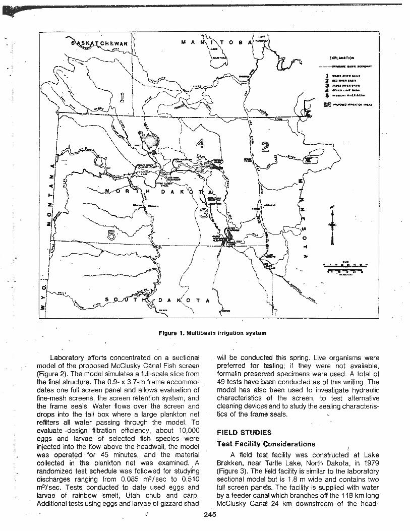
The Garrison Diversion Unit of the Missouri River Basin Project of the Bureau of Reclamation is a multibasin irrigation system (Figure 1). Potentially, about 100,000 hectares (250,000 acres) in east-
244
central North Dak ota will be served. Up to 55 m3/ sec (1950 ft3/sec) of water will be withdrawn from the Missouri River and delivered to the farmlands through a series of pumping plants. r8servoirs, and canals. A portion of irrigation return flo-Ns from the project will eventuaily enter the Hudson Bay drainage.
Canadian officials expressed concern .that several undesirable fish species may enter Canadian waters through Garrison Diversion Unit project features and have an adverse impact on sport and commercial fisheries in Manitoba. To address the international concern 2bout introduction of undesirable fish and the problem of preventing or minimizing fish passage, Bureau of Reclamation personnel considered several types of fish barriers . From among the various options available, USBR engineers and scientists selected a fixed fine-mesh screen with a 5° downward slope for iniensive laboratory study. Protection or survival of fish were not considerations and were not studied. Fouling, cleaning, corrosion and other operation and maintenance problems are being evaluated at a field test facility in North Dakota .
MATERIAL AND METHODS
LABORATORY STUDIES
All laboratory studies were conducted in the Engineering Laboratories of the Bureau of Reclamation's Engineering and Research Center in Denver, Colorado.
;
\' \ ', /\,
EXPLANATION
---OltM•A« IA•N 90UffOIUt1'
1 .,.., "'"'" .. ,11, a •oatrv11ta .. ,.
3 ,,,.., IIIVU IAlllf
4 lhtU LM'( .....
a ass~.UU lltvt.• &lllN
1 ,./ ' I -....._\
\ ~ l \
-"'
... t >
. ; I I ;I !ll ~
•• I M M .
Figure 1. Multibasin irrigation system
Laboratory efforts concentrated on a sectional model of the proposed McClusky Canal Fish screen (Figure 2). The model simulates a full-scale slice from the final structure. The 0.9- x 3.7-m frame accommodates one full screen panel and allows evaluation of fine-mesh screens, the screen retention system, and the frame seals. Water flows over the screen and drops into the tail box where a large plankton net refilters all water passing through the model . To evaluate design filtration efficiency, about 10,000 eggs and larvae of selected fi sh species were injected into the flow above the headwall , the model was operated for 45 minutes, and the material collected in the plankton net was examined. A randomized test schedule was followed for studying discharges ranging from 0.085 m3/ sec to 0.510 m3/sec. Tests conducted to date used eggs and larvae of rainbow smelt , Utah chub and carp . Additional tests using eggs and larvae of gizzard shad
245
will be conducted this spring. Live organisms were preferred for testing ; if they were not available, formalin preserved specimens were used. A total of 49 tests have been conducted as of this writing . The model has also been used to investigate hydraulic characteristics of the screen , to test alternative cleaning devices and to study the sealing characteristics of the frame seals.
FIELD STUDIES
Test Facility Considerations
A field test facility was constructed at Lake Brekken , near Ti\Jrtle Lake, North Dakota, in 1979 (Figure 3). The field facil ity is similar to the laboratory sectional model but is 1.8 m wide and contains two full screen pane'.ls. The facil ity is supplied with water by a feeder canal which branches off the 118 km long · McClusky Cana.I 24 km downstream of the head-

I l l
il' t "N .....
., 'J ._ .. 1
Figure 2. Laboratory sectional model
works. The McClusky Canal is the principal supply works for the Garrison Diversion Unit. The field test facility is primarily being used to study ooeration and maintenance-related problems , principally foul ing and spray cleaning systems , corrosion and materials selection, and accessory equipment evaluation . Accessory equipment being tested includes traveling screens , vibrating screens, automation C::evices, and debris handling systems. Maintenance needs , screen wear, and debris types and quantities are also being evaluated.
The spray cleaning device tracks upstream and downstream below the screen panels (Figure 4) . The spray cleaning device contains a manifold with a series of nozzles that create flat fan-shaped jets positioned to spray up through the bottom sides ·Of the screen panels. Fouling material is disrupted by the spray and swept downstream by the flow over the screens (Figure 5) . The spray cleaning system effectively cleaned the screens while the screens
246
were in operation. Field use allowed testing under more representa tive debris and fouling conditions than encountered in the laboratory.
Corrosion and materials selection were also stu·died. Two 70-mesh screen materials were tested in conjunction wi th the stainless steel frames . Stainless frames were selected to minimize corrosion and maintenance requirements. Phosphor bronze 70-mesh screen with a 90 percent copper content was tested to evaluate its algicide property and antifouling potentia l. Since the phosphor bronze has poor galvanic characteristics with respect to stainless, tests were c onducted both with and without cathodic protection to evaluate this problem. Monel screen (70 perce.nt nickel and 25 percent copper) was also tested in conjunction with the stainless frames.
Wear on the 70-mesh screens is being evaluated using photographs taken before and after operation (Figure 6) . Ten sp:ecific locatlons have been selected on each screen ,panel. Photographs are taken at these locations immediately after screen installation and after interva ls of operation. Dimensions of openings are measured from the photographs in a randomized process and analyzed statistically to obtain the size distribution. The size distributions will be compared to tlhe egg and larvae size distributions as measured in the laboratory to evaluate the probability of egg and larvae passage. The opening size distribution data for new and used screen will also be compared to evaluate we~r due to abrasion or corrosion.
A vertical traveling water screen mounted with 70-mesh screen was installed in the feeder canal immediately upstr,eam of the field model to evaluate the traveling screen's potential as a prefilter. The horizontal screen operation was then evaluated both with and without the traveling screen in operation.
Debris handiing and removal were also evaluated. In general , most of the debris was pumped to a lagoon by the use of sewage chopper pumps. A vibrating screen (Figure 7) mounted with 80-mesh screen just upstream of the traveling screen is used to reduce water cootent of the debris. Coarse debris collected on the trashracks has been handled manually to date. Automatic trashrack rakes would be used in the final structure.
Testing at the field test fadlity began on October 1, 1979. On October 9, 1979, 24-hour continuous operation began and continued until October 19, 1979. In 1980, the facility was operated continuously from June 19 until December 1.
Biological and Water Quality Considerations
A monitoring program was established for the field test facility. This program included water quality

~zr==-=w,== .
SCHE~!ATIC
TRAVELING SCREEN
__-,---j '""''fl~ INC ,c Il l { " ,
I '·· ·A '""""! I J • c•~ , ,. I
-- -.,j ~ __: n: .. -; .. ~ ~.~- t-,- •-: ~ ~;::_~-.;~- --- . .,_ .. . ! I • - ~ .. ·~- ·-
~r-r-,.-~ ~n/ . ~ -~ ' .
HORIZONTAL SCREENS TRASHRACK AND TRAVEL ING SCREEN BUILDING
Figure 3. Field model test facility
V -~
Figure 5. Spray cleaner operating (with screens in place)
I
Figure 4. Spray cleaner hardware (with screens removed)
analysis, analysis of biological material as 'related to screen loading and deterioration, and other environmental monitoring. Water quality analyses included complete chemistry (major cations, major anions, pH, EC, TDS), trace elements (Cu, Zn, Mn, Fe, Pb) , ·and nutrients (N03-N, N02-N, NH3-N, TN , ortho-P, TP) . Water samples for analysis were collected at three
247

NEW SCRE"EN
SCREEN AFTER 3 MONTHS OF USE
Figure 6. Magnified photos of 70 mesh phosphor bronze screen
Figure 7. Field facility vibrating screen
•• 248
sites at noon and midnight on Mondays and Thursdays during IE!le operation of the field test facility, preserved with acid, frozen, or refrigerated, and analyzed accorditlfg to established EPA water sampling and preservation protocol (Methods for Chemical Analysis o~ Water and Waste Water, U.S. Environmental Pratection Agency, March 1979).
Twice each day phytoplankton and zooplankton samples were co llected upstream of the traveling water screen, between the traveling water screen and the horizontal screens, and below the horizontal screens for laboratory identification and counting. Samples were preserved in 10 percent formalin. Fish and macroinvertebrates were sampled at random times from the horizontal screens and from the debris sumps and pres-erved in 10 percent formalin for laboratory identiffication. Samples for determination of dry weight bionmass were collected at the three previously descmibed sites to assess prefiltration potential of the tirraveling water screen .
PRESENT DESW.GN
Figures 8 a:nd 9 show the present horizontal screen panel amld seal design and the supporting structure. Also shown is the backup lower screen. Testing and desiign improvement continue and further 'minor modificatiions of this design are expected. Major design effrorts continue on the final facility.
The staintess steel_ framework provides corrosion-free seating surfaces which help to assure a positive seal.. Stainless flattened expanded metal welded to the screen framework supports the fine-mesh screen and strengthens the frames . The frames have been designed to withstand complete screen plugging without failure .
The pneumatic or inf!atable seals have proven to be an excellent 1feature since they seat over a wide area, are not sensitive to minor irregularities in the seating surface m to debris on the seating surface, and are not sensitive to warpage in the welded framework. Quick disconnect coupl ings allow rapid installation and removal. Adequate sealing can be obtained with an air pressure of 83 kPa ( 12 lb / in) . However, an arbitrary operating pressure of 152 kPa (22 lb/in2) has 1been established. An alarm system signals pressure loss in individual seals and excessive airflow in the main air supply line. ·
Laboratory Re sults
All tests oo the sectional model conducted to date have demo nstrated that the 70-mesh screen and design concept .~s an effective filter which prevents the passage of eggs and larvae of fish species of concern. ln 191'.9, in 12 test runs using 120,000 eggs and 120,000 farvae of rainbow smelt, no eggs or larvae passed §he seals or 70-mesh screen. In 1980, in 24 test runs l!l'Sing 50 ,000 eggs and 170,000 larvae

• I 1 i i I
l j
1
i
I i
support screen
·. ·: . .J. :/ _".: .· .. .: . .. ::· ..
·.•.
Figure 8. Present screen, frame, and seal c:~·sign
Figure 9. Present screen and seal design
of ra inbow smelt, no eggs or larvae passed the screen or seal. Also in 1980, with 40 ,000 eggs ai:,d 30,000 larvae of Utah chub, 50 ,000 eggs of carp , and 30,000 eggs of gizzard shad, no eggs or larvae passed the screen or seal. Additional testing is planned in 1981 .
249
I \
With clean laboratory water the screen was found to have a maximum discharge capacity of 0.465 m3 / sec per meter width or 0.425 m3 / sec per screen frame. laboratory sectional model studies have also shown !that effective screen cleaning could be obtained with ;a traveling spray cleaning system.
This spray cleaning device was effective either spraying down from above or up from below onto the operating screen.
Field Results
In general , the horizontal screen design with pneumatic seals , an automated spray cleaning system, and a pumped debris handling system has operated efficiently at the field test facility. The pneumatic seals were very effective and have withstood pressure from 6 feet of pooled water. The spray cleaning system operated by a continuous drive cablepulley system has also proved effective in dislodging impinged debris using an operating water pressure ot 207 kPa (30 lb/ in2) . The spray cleaning system will be automated for future operation.
The spray cleaning system removed . impinged debris equally from both the Monel and· ph.osphor-· bronze screen. The expected algicidal trait of phosphor-bronze screen was, therefore , unimportant. In addition. a high degree of pitting and deterioration occurred on the phosphor-bronze screen while very little occurred on the Monel screen . These factors , as well as reduced discharge capacity of the phosphorbronze screen, lead to the selection of Monel screen for additional field testing and for use in the final structure.
Debris loading was the major factor that controlled the maximum discharge capacity of the screens. As the debris load in the canal water became heavier, the screens fouled more rapidly. Increased fouling reduced the discharge capacity by reducing the effective filtration area ofthe screen. The criterion for screen cleaning was water flowing over the downstream end of the screens and into the debris trough. Consequently , as the debris load and fouling increased, the interval between spray cleanings was reduced. When debris loading got so heavy that the cleaning device could not keep the screens clean, the discharges were reduced. Under high fouling conditions, such as in midsummer with the Aphanizomenon load, discharges were substantially reduced. Continuous discharges of up to 0.279 m3/ sec per meter width of screen were obtained in spring and fall while midsummer discharges dropped as low as 0.062 m3 /sec per meter width of screen. Both of these discharges are considerably below those observed in the laboratory.
To date, for the types of debris encountered (copepods, cladocerans, rotifers , Aphanizomenon and Anacystis) it appears that the vertical traveling water screen is not an effective prenlter . The traveling water screen does not appreciably improve horizontal screen discharge capacity.
The pumped, closed conduit, debris handling system has proved effective . The commercially
available vibrating screen has also been used successfully to dewater this debris.
Water quality analyses for complete chemistry, trace elements, and nutrients are not yet completed. Generally, the canal water had a pH around 8.4 and conductivity around 1, 100 to 1,200. Dry weight biomass analyses are currently being conducted. Preliminary analysis indicates that the traveling water screen with 70-mesh screen does not prefilter canal water effectively. Evaluation of water quality effects on component corrosion and traveling water screen prefiltration efficiency is planned for 1981.
Present Direction
The photographic work to define the size distribution of openings in new and used screen and the size distribution of fish eggs and fish larvae will continue. Additional photographs will be taken as necessary and analyzed. Work has started on
· statistical analysis of data collected to date. No conclusions have been reached.
250
Tests are being conducted to evaluate the durability of various repair materials on 70-mesh Monel screen. lead-tin . solder, silver solder , and epoxy patches on Monel screen are being exposed to highvelocity sprays. With 200 hours of exposure, no patch failures have been noted .
The final structure is being designed to filter a discharge cf 28.3 m3/ sec. Additional structure can be added to increase the . discharge capacity to 55 m3/sec, the maximum final design discharge . This staged development recognizes that demand for irrigation wate1.· increases gradually and that a structure that can adequately filter 50 percent of the ultimate discharge should meet all needs for 10 to 20,. years.
Along with ihe final design a recommended operating crite11a will be developed. This is a critical aspect of the entire concept. Improper operation or improper mainte:rnance could lead to filtration failure . The structure is being designed to minimize the possibility of failure if it is operated improperly. Design improvements ars intended to reduce maintenance needs. Efforts are also being made to identify potential failure points in maintenance routines . Maintenance personnel will require extensive training to assure maintenance quality control.
ACKNOWLEDGMENTS
This study is a group effort and could not have been done without the conscientious work of a large number of individuals. James Sartoris, John Knoll , E. A. Seaman, James Delapp, Phillip Nelson, John Starbuck , Davidl Edwards, William Johnson, Danny King , Steven Hiebert, Eric Soderquist, Richard Lunde,

- ---·-----·- --- - ·- - --- ----Tim Felchle, Richard Dulin , and many others from the Bureau of Reclamation have done effective work on this study. Lee Mills and Thomas Jackson of the U.S. Fish and Wildlife Service are thanked for their comments and assistance in obtaining fish for laboratory testing. The comments of Milo Bell , Dale Henegar, Robert Pollock, David Tomljanovich, and Richard Weaver, who have functioned as Task Force consultants have been exceptionally helpful. Finally, a special thanks should be given to James Verzuh who has headed .the Task Force and who has generally
251
guided this work.. IH!s commitment to a high quality professional job an.ul sincerity in dea ling with people has helped to makE tilh is study a rewarding experience for all those involvoo.
REFERENCES CITED U.S. Environrrnental Protection Agency, 1979,
Methods for Chemical Analysis of Water and Waste Water, EPA-600/4-19-020.

ADVANCED INTAKE TECHNOLOGY FOR POWER PLANT COOLING WATER SYSTEMS
Proceedings of the Workshop of Advanced Intake Technology held at the Sheraton-Harbor Island Hotel
San Diego, California
April 22-24, 1981
Edited by
Philip B. Dorn and
Joseph T. Johnson
Co-sponsors:
Argonne National Laboratory Electric Power Research Institute
Southern California Edison Company United States Fish and Wildlife Service
United States Nuclear Regulatory Commission
AVAILAB°LE THROUGH NTIS