development of a finite element model of a 1998 audi a8
TRANSCRIPT

DEVELOPMENT OF A FINITE ELEMENT MODEL OF A 1998 AUDI A8 FOR CRASH ANALYSIS
Gustavo A. Aramayo, Alex Bobrek
Computer Science and Mathematics Division Oak Ridge National Laboratory
September 2001
Acknowledgment
Research was sponsored by the U.S. Department of Energy, Assistant Secretary for Energy Efficiency and Renewable Energy, Office of Transportation Technologies, Lightweight Materials Program, under contract DE-AC05-00OR22725 with UT-Battelle, LLC.
A finite element (FE) model of a 1998 Audi Model A8 has been developed for the crash analysis associated with the NHTSA NCAP program. The AUDI model A8 is an all aluminum four-door passenger vehicle; it is classified as a ‘large sedan’ car. The model developed is to be used to analyze frontal impact against a rigid barrier as specified in standard procedures associated with the assessment of passenger vehicles crashworthiness. The model development was based in the generation of a finite element mesh that is based in the actual measurement or mapping of most of the car components. This experimental mapping is the result of determination of the surface contours on a fully disassembled vehicle using a Faro Arm (a coordinate measurement device). The material properties are obtained via uniaxial testing of metal coupons of selected components of the vehicle. Load-deflection tests were also performed on critical components in the engine, suspension, transmission and forward bumper support regions. The generation of the model was performed using standard of-the-shell software (TrueGrid™), the numerical analysis that simulates the 35 mph frontal impact was performed using the LS960 version of LS_DYNA™, post processing was done using the program LSPOST™. Computation was performed in the IBM PS2.5 massive parallel computer at ORNL. MODEL GENERATION The finite element model has been generated using a projection method to mold a block mesh onto a desired shape. In this technique, TrueGrid constrains mesh faces to lie on IGES surfaces that are experimentally obtained and imported directly into the program.
The model IGES surfaces are obtained from the measurement of the actual geometry of fully disassembled visible car components. The vehicle was disassembled so that, ideally, it is physically possible to access each component for correct measurement. For actual implementation into TrueGrid, the IGES data is converted into the Viewpoint data format. This data is composed of two files; one identifies nodal connectivity in the form of polygonal surfaces with nodal coordinates defined in the other file. TrueGrid uses these surfaces as the projection targets that define each of the parts of the vehicle. There are a number of advantages to using the projection method. Most importantly, the geometry and the mesh topology are independent. Also it is possible for surfaces to have relatively small gaps or even small overlap without detrimental consequences to the model. When surfaces that have gaps or overlap between each other like the input data used in this model are combined, a node that is projected to its combined surface is simply moved to its closest point which lies on one of the component surfaces and the gap/overlap is simply disregarded. When adjacent faces are projected onto surfaces, which do not meet one another, then these surfaces are tangentially extended and the mismatching edges are moved to the projected surface intersection. There are nodal generating relaxation techniques that interpolate internal nodes, relative to the surface edge, that assure that the generated mesh does not contain degenerated elements. These features save considerable amount of geometry cleanup time that is normally associated with IGES surfaces of poor quality. From an initial batch of near 300 IGES surfaces that were initially measured, the first step was to eliminate obvious errors like large gaps, large surface overlaps, simplify the size of the measured surface by splitting large surfaces into smaller components that are more amenable to simple projections. The actual number of IGES surfaces actually used in the model generation was then reduced to 254 that accounted for both sides of the car and it used the symmetrical properties existent to simplify the number of surfaces that was translated into a Viewpoint format. The finite element model generated consists mainly of shell elements and the techniques described above are applicable to this class of elements. The beam components in the model are interactively generated by specifying the nodes that are connected by the element and a third node that specifies the orientation of the beam cross section. Solid elements in the model are associated mainly with components that can be synthesized by geometric primitive shapes like solid rods and solid hexahedra. Traditionally, in a finite element model based in a well defined input surface data, contact between the internal components can be defined by a unique ‘single surface’ class contact of the analysis program. For this class of contact to be used is necessary that the adjacent surfaces in the vehicle be mapped so that there is actual physical separation associated with the component thickness and any existing gap. When this requirement is not satisfied, the analysis program will move interfaces nodes so that initial penetrations are eliminated. Initial penetrations are undesirable since they introduce initial forces in the model that tend to distort the geometry and final response. Thus, to eliminate this source of error, the model generated herein uses a combination of ‘single surface’ type contact
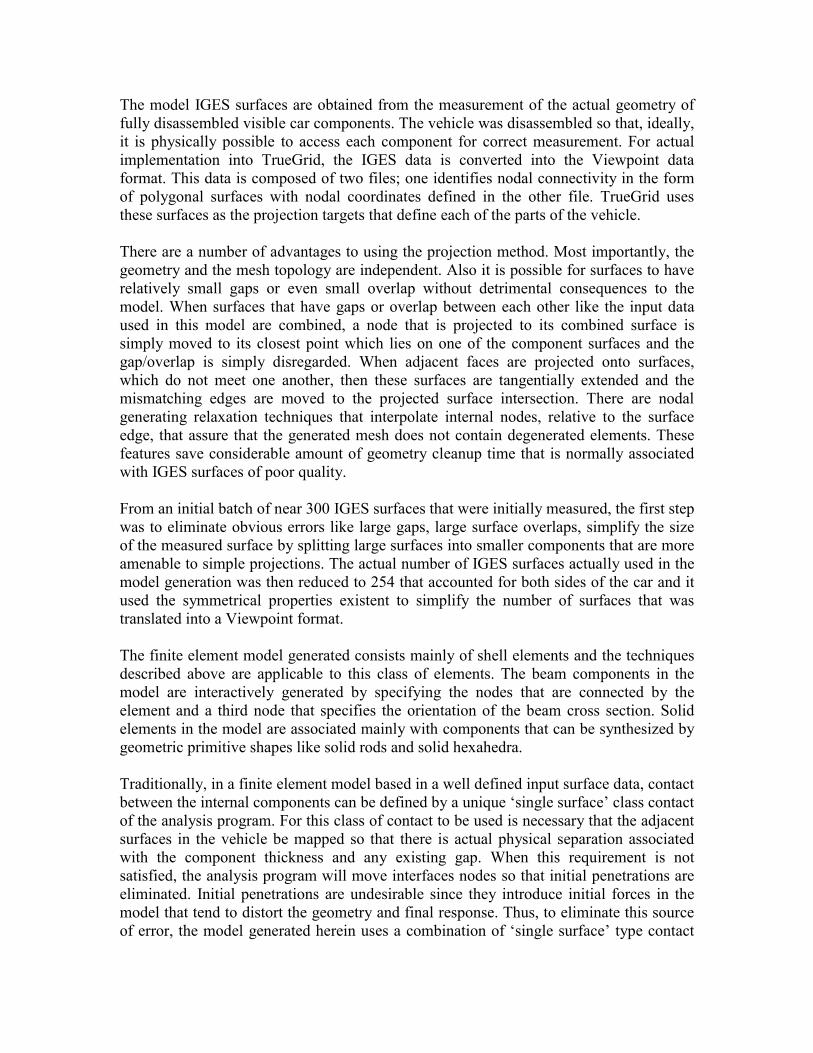
and several ‘node-to surface’ class contact algorithm. In this scheme of the contact careful attention is considered so that components are not included in two or more contact entities. The use of several contact classes that address specific regions in the model alleviates the requirement that actual thickness separation be considered in the part contact modeling. The level of complexity of the generated model can be illustrated in detail by observing the development of some of the vehicle components that form the space frame of the car cabin. In the components of this frame experimental measurement was made only in the external visible surfaces and measurements were taken at either the external OR internal surface locations, the interior components of some of the frame members were developed manually based on section cut-offs at several locations of a given frame component. Figure 1 illustrates the development of the B-pillar in which experimental measurement was possible for the exterior envelop components of the pillar. The internal structural components (that part of the assembly contained within the external envelop) that were developed as noted above are also shown in this figure. Figure 1(a) shows the complete (left and right side) FE model of the B-pillar, Figure 1(c) shows the outer shell component based on experimental measurement of the part shapes, Figure 1(b) the inner shell component also based on experimental measurements, and Figure 1(d) illustrates that part of the B-pillar contained within the outer and inner shells that was developed from actual samples of the pillar.
(a) (b) (c) (d)
Figure 1- Development of the FE model of the B-pillar. In similar fashion, the A-pillar/hinge-column is a combination of experimentally measured components and manually generated interior components that are based on cross-section cut-off of this part. Figure 2 illustrates the interaction of these parts that form the FE of the A-pillar/hinge column. Figure 2(b) illustrates the inclusion of the

internal bulkhead type structure in the hinge-column and the internal forgings contained within the A-pillar.
(a) (b) Figure 2. Development of the FE model of the A-pillar/Hinge column. The rocker panel assembly is also a combination of models developed from experimentally obtained surfaces and model developed manually with geometry based in physical cut-offs of the structure. Figure 3(a) shows the model of the entire rocker panel, Figure 3(b) shows the interior plates housed inside the rocker panel structure.
(a) / (b) Figure 3. Development of the FE model of the Rocker Panel Structure.

The forward section of the Audi car, Figure 4, presented a level of complexity that required special attention in modeling. The components of this section shown in terms of equivalent components of a traditional vehicle are described in this figure. The top components is part of the top rail that in this vehicle is attached to the lower rail at a point near the attachment of the collapsible tube (that houses the bumper piston) supports the bumper. The lower structure is the engine cradle that is attached at both ends to the lower rail. The engine cradle provides support to the low A-arm of the front suspension; it provides support to the rear engine and to the transmission mounts. Both rear sections of the top and low rail are welded to the cab assembly.
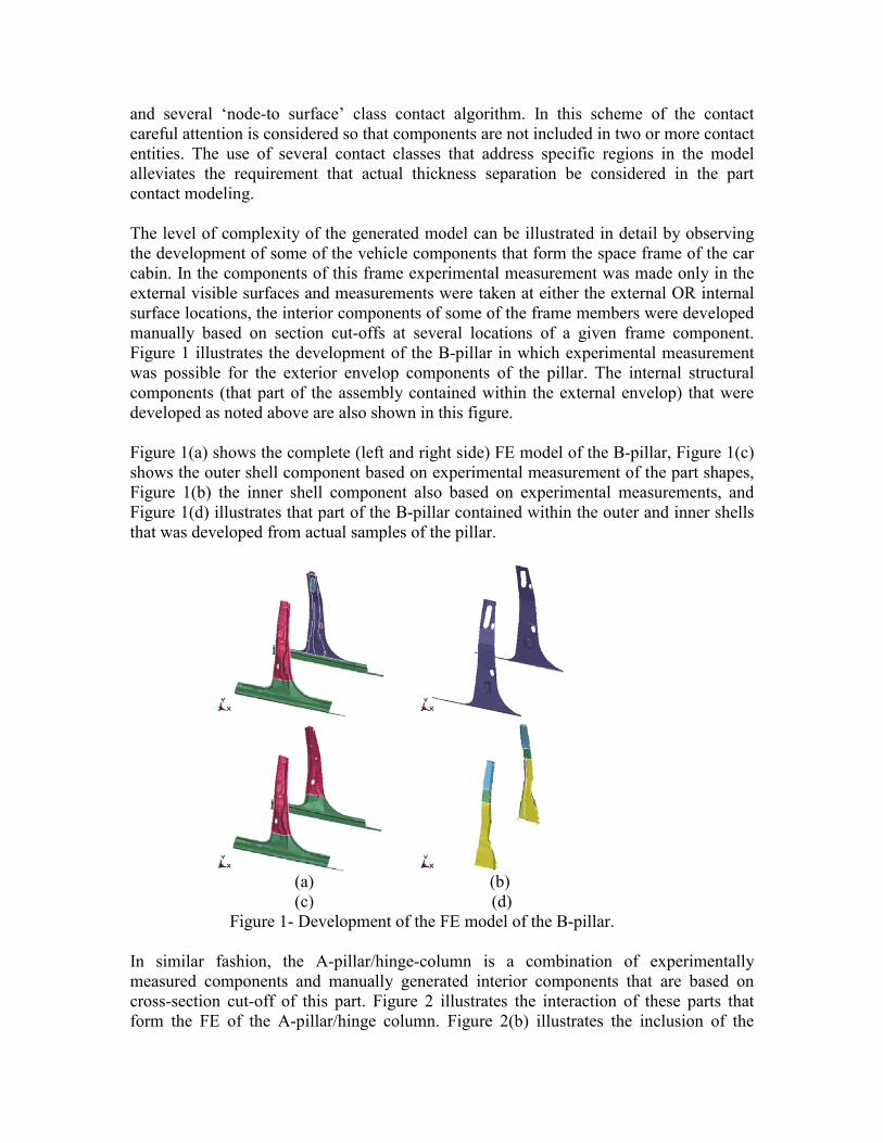
Figure 4- Audi A8 Forward Bumper Support Assembly The state of deformation of the Forward Bumper Support assembly is shown in Figure 5. Figures 5(a) and 5(b) shows the deformed and initial configuration of this section. Figures 5(c) and 5(d) illustrate the side view of the assembly after and before the 35 mph collision. The engine has been removed for clarity. The kinematics of the deformed shape of this section has been verified using as a guide the results of full-scale experiments on the vehicle as documented in Reference 1. Results of the crash simulation show good correlation in the state of deformation of the lower rail when compared with the full scale testing discussed in Ref. 1. The simulation results also show that the deformation of the engine cradle is similar in shape to the deformation shape shown in Ref. 1, however, the amplitude of deformation is slightly smaller. The FE model of the A8 car developed herein, has deficiencies in the engine cradle modeling that are attributable to the nature of the IGES surfaces used in the model development. These deficiencies are discussed in a later section of this report.
(a) (b) (c) (d)
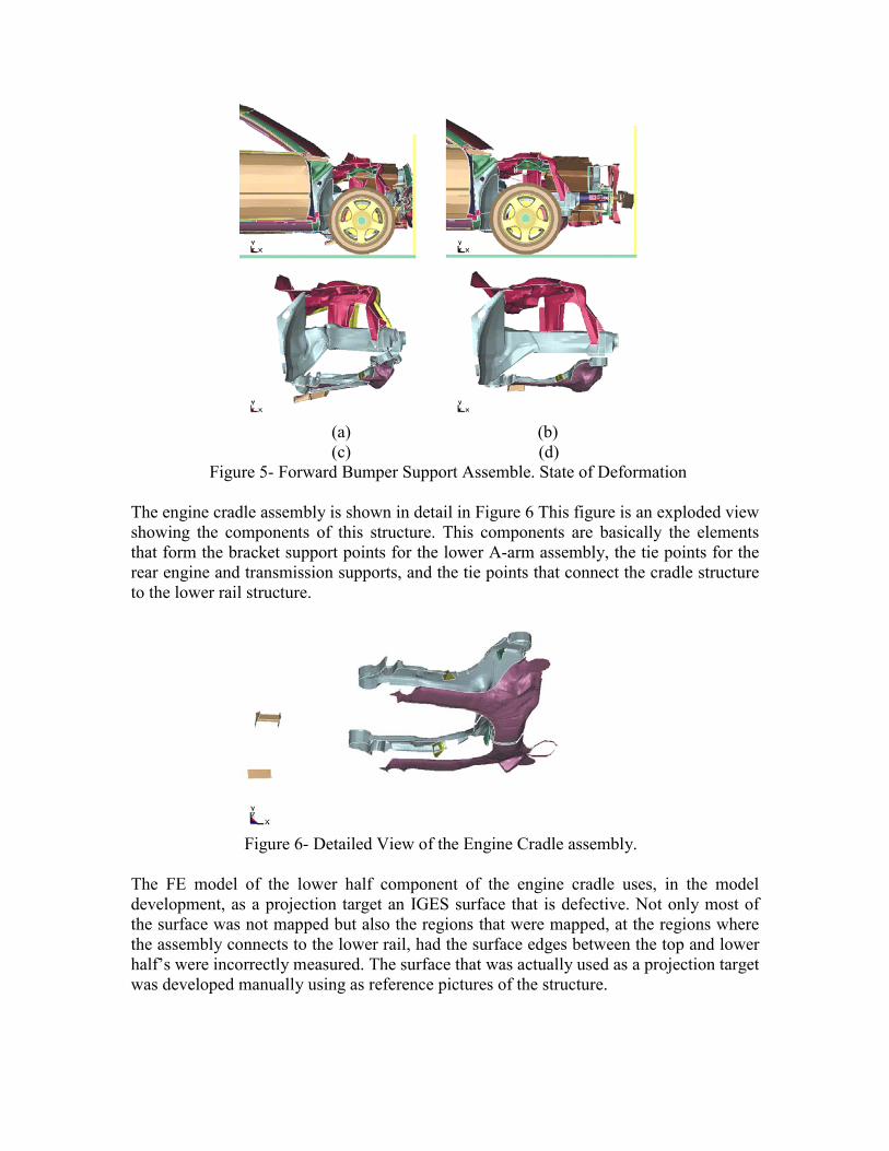
Figure 5- Forward Bumper Support Assemble. State of Deformation The engine cradle assembly is shown in detail in Figure 6 This figure is an exploded view showing the components of this structure. This components are basically the elements that form the bracket support points for the lower A-arm assembly, the tie points for the rear engine and transmission supports, and the tie points that connect the cradle structure to the lower rail structure.
Figure 6- Detailed View of the Engine Cradle assembly. The FE model of the lower half component of the engine cradle uses, in the model development, as a projection target an IGES surface that is defective. Not only most of the surface was not mapped but also the regions that were mapped, at the regions where the assembly connects to the lower rail, had the surface edges between the top and lower half’s were incorrectly measured. The surface that was actually used as a projection target was developed manually using as reference pictures of the structure.
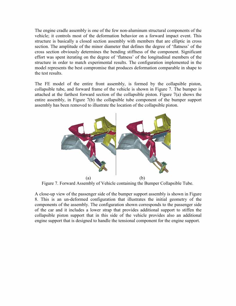
The engine cradle assembly is one of the few non-aluminum structural components of the vehicle; it controls most of the deformation behavior on a forward impact event. This structure is basically a closed section assembly with members that are elliptic in cross section. The amplitude of the minor diameter that defines the degree of ‘flatness’ of the cross section obviously determines the bending stiffness of the component. Significant effort was spent iterating on the degree of ‘flatness’ of the longitudinal members of the structure in order to match experimental results. The configuration implemented in the model represents the best compromise that produces deformation comparable in shape to the test results. The FE model of the entire front assembly, is formed by the collapsible piston, collapsible tube, and forward frame of the vehicle is shown in Figure 7. The bumper is attached at the farthest forward section of the collapsible piston. Figure 7(a) shows the entire assembly, in Figure 7(b) the collapsible tube component of the bumper support assembly has been removed to illustrate the location of the collapsible piston.
(a) (b) Figure 7. Forward Assembly of Vehicle containing the Bumper Collapsible Tube. A close-up view of the passenger side of the bumper support assembly is shown in Figure 8. This is an un-deformed configuration that illustrates the initial geometry of the components of the assembly. The configuration shown corresponds to the passenger side of the car and it includes a lower strap that provides additional support to stiffen the collapsible piston support that in this side of the vehicle provides also an additional engine support that is designed to handle the tensional component for the engine support.

Figure 8- Initial configuration of the Passenger side Bumper support assembly The structure shown in Figure 8 represents a non-traditional approach to the standard lower rail bumper support that is most commonly found in other vehicles. In the Audi A8 (and A4, A6) this structure provides a quasi-active energy absorbing mechanism in which different levels of imposed energy activate specific components for energy management. For velocities below 15 mph most of the energy is dissipated in the ‘dislocation’ of the ‘bumper piston’ from its support. At higher velocities, once the ‘bumper piston’ makes contact with its support structure, there is a gradual axial buckling of the tube support. Finally as the collapsible tube bottoms-out the remaining energy is absorbed by the deformation of the lower and upper rails. Figure 9(a) shows the state of deformation at the end of the ‘bumper piston’ travel just before the buckling of the tube support is initiated. Figure 9(b) illustrates the state of deformation at the end of the tube buckling. Figure 6(c) illustrates the subsequent deformation of the lower and upper rails (and engine cradle).
(a) (b) Figure 9- States of Deformation of the ‘Bumper Piston’/Collapsible Tube Assemblies Modeling of the structure shown in Figure 8 presents interesting problems. The assembly is characterized as one in which a rigid shaft that is initially tied to its support, breaks away sliding on its supports and makes contact with the interior wall of a tube that is

initially non-deformed and buckles subsequently presenting a state of deformation characterized by a compressed accordion like configuration. The use of a single-surface contact model to characterize the contact between the components of the structure described above becomes invalid in particular when the effects of component thickness are not incorporated in the model. Thus to model the contact effects of the structure it was necessary to use a variety of contact models that address all the possible combination of contact between the structure components. These contact entities are then: · Single surface contact model for the buckling of the collapsible tube · Single-surface-contact model for the connecting strap between the lower rail and the bumper piston support, ·Node-to-surface model for the bumper piston and interior of the collapsible tube ·Node-to-surface model for the bumper piston and interior of the lower and upper rail structures · Node-to-surface model for contact between the exterior of the collapsible tube and the bumper piston support In order to reduce the time spent in the nodal search in the contact models, specific windows were allocated for each contact entity. Also different contact entities were assigned for the left and side of the structure. The penalty functions have been determined by iterating on the simulation results and the values used represent those values, which result in minimum penetration of the contact interfaces. The need of the complex contact model used in the model results in the need of using integration steps that are rather conservative in order to maintain stability of the contact models. Details of the mathematical model of the Audi model A8 are shown in Figure 10.

Figure 10- Mathematical Model of the A8 Audi Vehicle MODEL STATISTICS The finite element model of the A8 Audi developed has the following characteristics: Number of Node points……………..295466 Number of Solid Hexahedra………...2411 Number of Shells……………………290048 Number of beam elements…………..797 Number of Component Materials……198 Number of Contact Interfaces……….37----- 1 single-sided ----- 19 tied ----- 17 node-to-surface Equivalent Weight of Model………….1.718 Metric Tonnes MODEL MATERIAL DATA All the finite element model components that are represented as beam elements have material properties that correspond to a mild steel with a typical modulus of elasticity of 200,000 MPa, the material model is either a pure elastic model or a rigid material. Most of the front suspension components modeled as beam use the elastic material. Most of the rear suspension components and some links in the forward suspension are modeled as

rigid links (rigid material). The components such as hinges, components that connect suspension links to structural shell are normally modeled as rigid links. The shell components associated with the exterior boundary of the car, the front assembly chassis that supports the forward bumper, with the exception of the engine cradle have material properties with parameters obtained from uniaxial testing of coupons obtained from a vehicle assembly specially obtained for this purpose. Twenty-nine tests have been conducted of components that are believed to represent critical items in the vehicle. Results of the material characterization testing can be obtained from Reference 2. That part of the forward structure that supports the engine and transmission (engine cradle) and provides support to the lower A-type arm is made of steel. The material model data for these components corresponds to mild steel, with stress-strain curve explicitly specified and no strain rate effects are considered. The material model corresponds to a linear isotropic plasticity model with failure based in a strain limit. Additional testing was performed to obtain load-deflection curves of the Forward Engine Mount, Rear Engine Mount, and Transmission Mount. This data was used to calculate equivalent beam properties of these components. These mounts have been modeled as Hughes-Liu beam elements using a piece-wise linear isotropic plasticity material model that includes failure. The engine and transmission mounts used in the test program are shown in Figure 11.
Figure 11. Rear Engine, Forward Engine and Transmission Mounts. The experimental data can be obtained from Reference 3. The load-deflection of the collapsible strut that connects the forward bumper to the forward assembly of the vehicle has been experimentally obtained. The breakaway load at which the piston assembly separates from the collapsible strut has been obtained. This component was implemented using a spot welding model where the failure load for the weld was made equivalent to the experimentally obtained break away force. The front
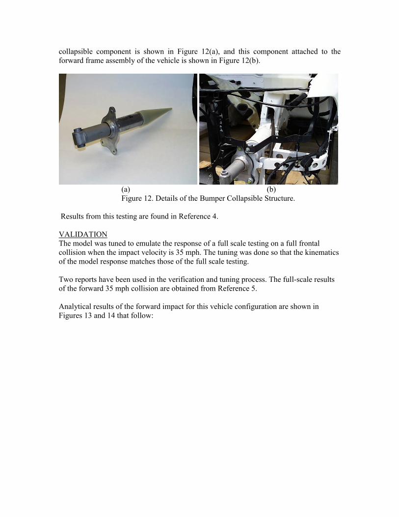
collapsible component is shown in Figure 12(a), and this component attached to the forward frame assembly of the vehicle is shown in Figure 12(b).
(a) (b) Figure 12. Details of the Bumper Collapsible Structure.
Results from this testing are found in Reference 4. VALIDATION The model was tuned to emulate the response of a full scale testing on a full frontal collision when the impact velocity is 35 mph. The tuning was done so that the kinematics of the model response matches those of the full scale testing. Two reports have been used in the verification and tuning process. The full-scale results of the forward 35 mph collision are obtained from Reference 5. Analytical results of the forward impact for this vehicle configuration are shown in Figures 13 and 14 that follow:

Figure 13- Analytical Results, Side View of Front Impact Event
Figure 14- Analytical Results, Top View of Front Impact Event

There is an additional full scale testing of a partial model of the Audi A8, in this test the engine hood and front fenders have been removed in order to observe and collect data on the engine kinematics and the front collapsible section of the forward bumper support. Results of this test are documented in Reference 6. The input file and plot files of the simulation of the forward impact against a rigid wall are found in machine EAGLE, directory /tmp/gpfs600a/gaa/AUDI/tmp24. REFERENCES 1- Aluminum-Technologie im Karosseriebau-Audi Space Frame ASF Audi AG D-85045, Ingolstadt 2- Mechanical Evaluation of Aluminum Specimens Internal Memorandum: Chris O. Stevens (M&C) to G. A. Aramayo October 27, 2000 3- Evaluation of Mounts Letter ELC-2001.01.04 Internal Memorandum: E. Lara-Curzio et al (M&C) to G. A. Aramayo et al January 8,2001 4- Mechanical Evaluation of Bumper Piston Letter ELC-2000.11.01 Internal Memorandum: C.O. Stevens (M&C) to G.A. Aramayo November 2, 2000 5- New Car Assessment Program (NCAP) Frontal Barrier Impact Test 1998 Audi A8 4 Door August 18, 1999 6- 35 MPH Frontal Barrier Impact Test 1998 Audi A8 4 Door Sedan, NHTSA Number RW0511 Report Number: MGA-2001-TTD2-001 March 8, 2000