development of a doorframe support … · 2014-08-31 · page 1 development of a doorframe support...
TRANSCRIPT
Page 1
DEVELOPMENT OF A DOORFRAME SUPPORT STRUCTURE IN GLASS-REINFORCED POLYPROPYLENE COMPOSITES: MATERIAL
VALIDATION & PROCESS ENHANCEMENTS
Duane Emerson, Michael Ruby, Manfred Reif Celanese Corp.
Michael Begert, Eric Schneider EDAG GmbH & Co. KGaA
Tobias Joppich, Sebastian Baumgärtner Fraunhofer Institute for Chemical Technology
Abstract
A 2013 study in Germany evaluated the use of unidirectional (UD)-glass-reinforced polypropylene tape-based composites in the production of a doorframe support structure for the storage-bin door of a commercial truck. After materials characterization and extensive simulation work, a comprehensive process study was undertaken to examine the effects of ply layup and fiber orientation to understand how UD-glass fibers moved during molding. A further microscopy study looked for fiber twisting or breakage and consolidation quality in cross-section across the length of the part. A thermal study, where thermocouples were inserted between plies within the laminate stack prior to preheating/consolidation and molding, helped researchers define the correct process window to avoid cold-molding and glass breakage. Last, a process optimization study sought to reduce cycle time for a semi-automated four-step production process, which demonstrated the potential to produce structural composite parts in 60 sec or less. Versus the incumbent stamped steel doorframe support, the all-thermoplastic composite version offered improved performance yet was lighter weight and comparable in costs even without optimizing the design for composites.
Background
Depending on geography, most automakers and commercial truck OEMs are tasked with either significantly improving the fuel efficiency or extensively reducing the greenhouse-gas emissions of their vehicles within a relatively short timeframe. This must be accomplished without sacrificing vehicle safety, comfort, or reliability, and without allowing cost increases to price vehicles out of reach of customers. To meet these mandates, engineering teams at OEMs and tier suppliers are proceeding along two major fronts: exploring alternative powertrain options that are considerably more efficient than current internal combustion engines; and seeking design and materials substitution options that allow considerable mass to be reduced from vehicle structures. Because such large changes must be made so quickly, OEMs are far more open to considering non-traditional materials and processes than ever before. This report describes a project conducted in 2013 to evaluate the conversion of a steel doorframe support structure to composites on the close-out/door for a storage bin on the cab of a commercial truck. Part geometry and tooling were carryovers from a previous study conducted several years earlier with a different thermoplastic composite material.
Page 2
2009-2011 Organosheet Lightweighting Study
Between 2009 and 2011, engineering-services company, EDAG GmbH & Co. KGaA1 conducted a lightweighting (mass reduction) study for its customer, a commercial truck OEM to evaluate opportunities to take mass out of a structural support frame produced in stamped steel [1]. The purpose of this demonstration project was to highlight composite materials and processes that could be used to reduce mass while improving performance. EDAG chose a preconsolidated sheet-form thermoplastic composite generically called organosheet in Europe
that was formed via compression molding. This particular material (Tepex dynalite 102-RG600(3)/47% from Bond-Laminates GmbH2) featured a polyamide 6 (PA6) matrix reinforced with a woven fiberglass fabric. This material is commonly used in automotive applications in Europe (e.g. for seat frames and front-end modules). EDAG was already familiar with the material from previous projects and selected it for this demonstration owing to its high strength, low specific mass, and moderate cost.
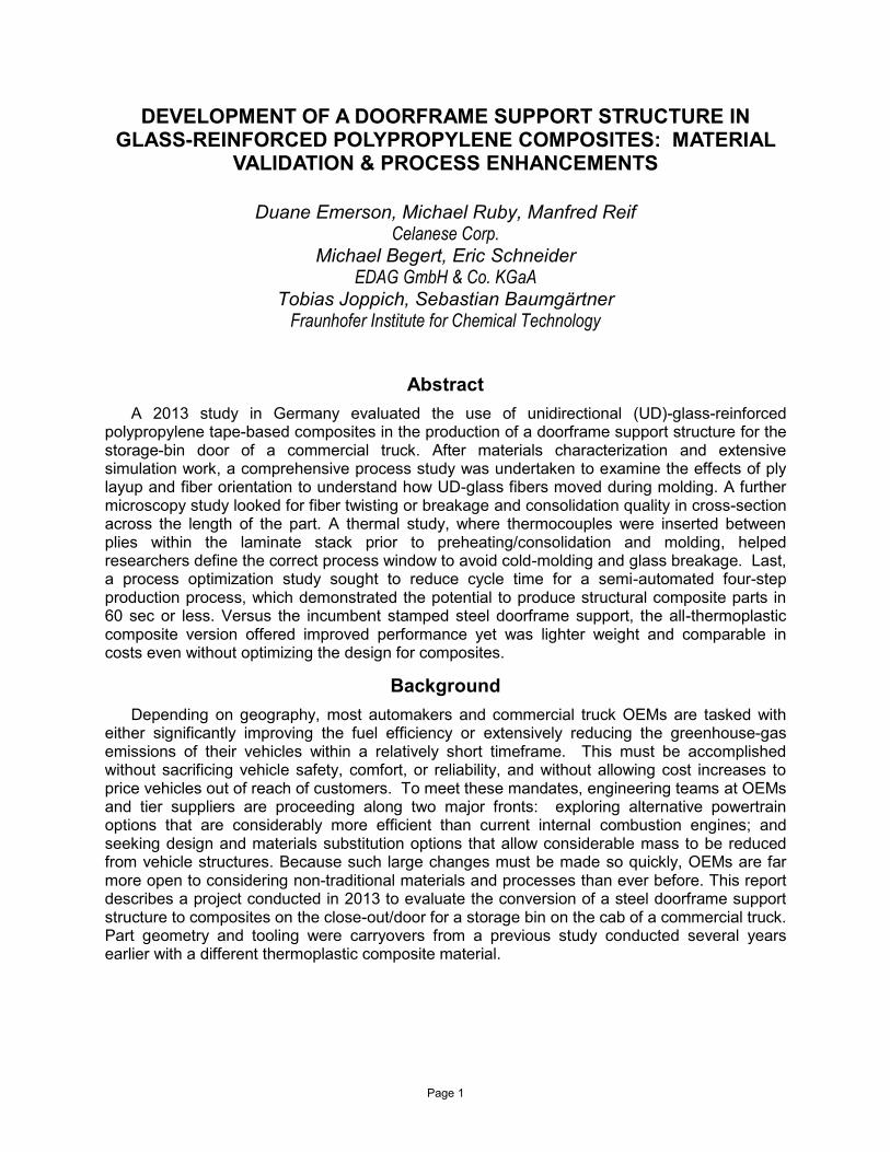
The project began with the OEM customer providing dimensional details (in the form of computer-aided design and engineering (CAD/CAE) files for the part, which measured 50 x 75 cm. Functionally a support frame with a central "window/cutout" that is welded to a steel door skin, the doorframe part is used on several models of commercial truck cabs (Figure 1) produced by the OEM customer. Researchers at EDAG felt that the part would make a good demonstrator for this project owing to its relatively large size (allowing significant mass to be removed) and its simple geometry and relatively flat shape (which would more easily permit a steel to composite conversion without design optimization). Since space was limited by the external geometry of the steel skin, there was little opportunity to change the design to better make use of the benefits of composites. Owing to the fact that the incumbent design was stamped in steel and this design would have to be replicated in compression molded organosheet composite, a few minor concessions were made to both radii (making them less sharp to reduce stress concentrations and make the part easier to mold) and allowing the part to become slightly thicker (to achieve higher part stiffness as well as accommodate the composite material's lower ultimate strength). Goals set for the project were to achieve significant mass reduction vs. the steel benchmark while maintain or increasing stiffness but without sacrificing
maximum stress and strain (σmax <231MPa; εmax <0.3%), which was required for the part to
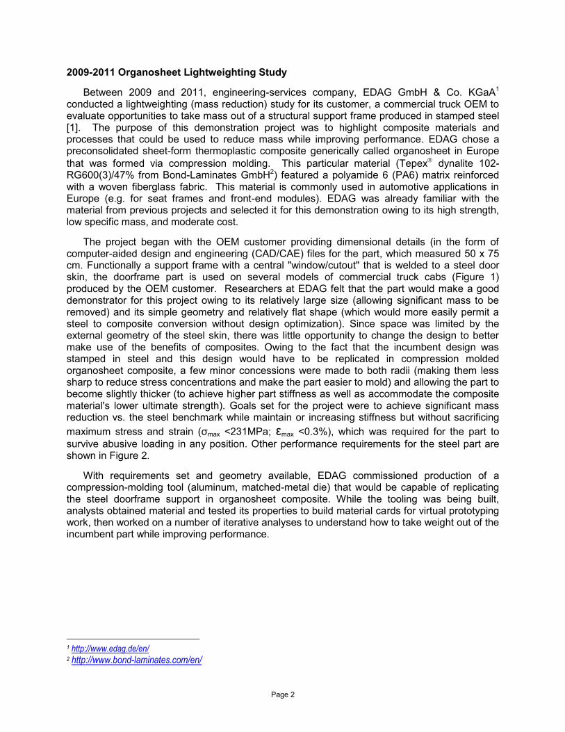
survive abusive loading in any position. Other performance requirements for the steel part are shown in Figure 2.
With requirements set and geometry available, EDAG commissioned production of a compression-molding tool (aluminum, matched-metal die) that would be capable of replicating the steel doorframe support in organosheet composite. While the tooling was being built, analysts obtained material and tested its properties to build material cards for virtual prototyping work, then worked on a number of iterative analyses to understand how to take weight out of the incumbent part while improving performance.
1 http://www.edag.de/en/ 2 http://www.bond-laminates.com/en/
Page 3
Figure 1: Location of 50 x 75 cm storage doorframe support on backside of storage door on commercial truck cab
Figure 2: Geometry and performance specifications for baseline steel doorframe support structure

Page 4
Results of Organosheet Lightweighting Study
Preliminary CAE results predicted mass would be reduced 7.9% vs. steel. Torsional compliance was slightly better at 0.6%, but that was achieved at the expense of flexural modulus (whose values were reduced by 7.4%). Analysts believed they could improve these results further, so more simulation work was done to evaluate the effect of selectively adding patches of additional organosheet for extra reinforcement in key areas, which did yield better results.In this variant, the optimized result had a maximum thickness of 8.5 mm. Finally, as an exercise in what was possible with this material, analysts considered what could be done if the part geometry and tooling could be modified significantly so that thickness could be increased. Key changes that were made included the addition of over-molded ribs in 60% short-glass PA6 as well as patches of additional organosheet material in areas requiring greater stiffness. Simulation results showed that these changes would appreciably increase geometric stiffness. Additional work on rib topology increased part thickness by 1.8 mm but offered much better performance. Finally, actual parts in the initial geometry (without ribs or patches) were molded and tested (shown in Figure 3). In that case, mass was reduced by almost 33% (from 2.329 to 1.693 kg), while maximum stress and strain were maintained within the elastic range of the material (σ = 38.2 MPa; ε = 0.2%). In the best optimized geometry (where thickness was not a limit), the patches and ribs increased maximum wall section to 6.5 mm, which was considerably thicker than the incumbent steel part's 0.9 mm. Researchers concluded the goals of the study had been met, although they acknowledged that if they had had greater freedom to modify the design, then performance and stiffness / weight targets could have been improved further. The part was shown at several international expositions and generated significant interest by transportation OEMs in several segments.
Figure 3: Final organosheet doorframe support structure with mounting hardware attached
2013 Lightweighting Study: Thermoplastic Composite Laminates
Owing to the successful reception results from the earlier lightweighting study received, as 2012 wrapped up, researchers at EDAG began looking for another demonstrator project to showcase benefits of changing from metals to composites. As such, they contacted staff at the research institute, Fraunhofer Institute for Chemical Technology (ICT3) as a possible study partner.
3 http://www.ict.fraunhofer.de/en.html

Page 5
As luck would have it, around the same time, ICT and Celanese Corp.4, a global resin supplier and producer of UD glass and carbon fiber-reinforced composite tapes began discussing their next project. During the time period when EDAG worked on its earlier organosheet lightweighting study, ICT and Celanese collaborated on an automotive underbody shield demonstrator project [2-4] in which UD-glass tapes (in the form of tailored laminates and fabric weaves) were combined with direct-long fiber thermoplastic (D-LFT) to evaluate performance improvements and process behavior.
All three companies were introduced, discussions ensued, and EDAG, ICT, and Celanese all agreed to work together on a new project involving the doorframe support structure, but this time with a different thermoplastic composite. Negotiations were completed early in 2013, the consortium was fixed, and the project commenced right away. EDAG agreed to be responsible for materials characterization and CAE analysis, plus supplied previous tooling for the new project; Celanese formulated and provided UD-glass and carbon fiber tape-based materials for the study and help with characterization; ICT molded and tested plaques and larger doorframe support parts plus conducted both a novel process study as well as process optimization work. Details of that study are provided in this report and an overview of work is shown in Figure 4.
Part 1: Materials Selection & Characterization
As it had before, the new lightweighting study began with characterization of the materials that would be used in the study. Celanese had suggested three grades of UD-fiber reinforced thermoplastic composite tapes for the study, whose general properties are shown in Table I:
a 70 wt-% continuous glass fiber-reinforced tape with a polypropylene (PP) matrix (Celstran CFR-TP PP GF70, henceforth: PPGF70);
a 60 wt-% glass fiber-reinforced tape with a polyamide 6/6 (PA66) matrix (Celstran CFR-TP PA66 GF60, henceforth: PA66GF60); and
a 60 wt-% 24K-tow carbon fiber-reinforced tape with a PA66 matrix (Celstran CFR-TP PA66 CF60, henceforth: PA66CF60) [7].
These tapes are laid up to produce laminate-based composites that can be formed via compression molding or lower pressure thermostamping, depending on the geometry involved. Owing to their high specific strength at low mass, moderate cost (approximately the same as organosheet), ability to modify final part properties by changing number and orientation of tape plies, recyclability, rapid processing, and ability to reuse scrap, they have a history of use in a variety of structural and semi-structural applications in the aviation and aerospace industries, but are fairly new materials for the automotive and commercial truck industries, with many OEMs currently evaluating these materials. Of the three grades initially suggested by Celanese, PA66 matrix (used in two of the candidate tapes) offers properties that are similar to the PA6 matrix used in the organosheet composite from the earlier study. However, PA66 is considered to be the less hygroscopic of the two resins, so can provide more consistent mechanical properties and dimensional stability over time. The other matrix, PP, is lower temperature (not an issue in this application) and less stiff than the PA grades but is a very tough polymer with a very low specific gravity, lower cost, and that does not have the moisture sensitivity that can be an issue with polyamides. Two types of unidirectional fiber reinforcement were used: more economical, easier to process, but heavier E-glass in the PP and one of the PA66 grades; and higher performing and lighter but more costly carbon fiber in the other PA66 grade. . Initially all three materials were evaluated, but later the focus shifted to the PPGF70 grade.
4 http://www.celanese.com/

Page 6
Figure 4: Project overview showing three phases of work
Table I: Preliminary characterization of candidate materials (supplied in widths of 50 mm)
Property PPGF70 PA66GF60 PA66CF60
Polymer Matrix Polypropylene (PP) Polyamide 6/6 (PA66) Polyamide 6/6 (PA66) Reinforcing Fiber E-glass Carbon fiber Carbon fiber Density 1.67 g/cm3 1.73 g/cm3 1.46 g/cm3 Fiber Content 70 wt-% 60 wt-% 60 wt-% Fiber Volume 44 vol-% 39 vol-% 49 vol-% Tape Thickness† 0.26 mm 0.28 mm 0.17 mm Tape Width (max.)‡ 305 mm 305 mm 254 mm Tape Areal Weight† 435 g/m2 485 g/m2 240 g/m2 †Nominal values shown. Actual values may vary. ‡ Custom tape widths may be available. Slit tapes are available to 6 mm.
Table II: Typical experimental characterization of fiber composites (based on needs of an application)
No. Test Type Characteristics Compare with Isotropic Materials
1 Tensile test in the longitudinal fiber direction
E1+,v12+,X1+, ɛ1+ Only a tensile test
2 Tensile test transverse to the fiber longitudinal direction
E2+,v21+,X2+, ɛt+
3 Cyclic tensile test at +/-45o G12, S12, ɛ12 el, ɛ12 pl, y0, C, p,
12 4 Cyclic tensile test at +/-67.5o Yc, Y0, Ys, coupling factor b 5 Dynamic tensile tests Strain-rate dependence Strain-rate dependence 6 Compression test in the longitudinal
fiber direction E1-,v12-,X1-, ɛ1- Compression tests possible
7 Pressure test perpendicular to the fiber longitudinal direction
E2-,v21-,X2-, ɛ2-
8 3-point bending tests Validation Validation 9 4-point bending tests Validation Validation 10 Double cantilever beam (DCB) test Interlaminar behavior of mode I Completely eliminated
Page 7
One significant difference between the previous organosheet material and the UD-tape laminates is the greater design flexibility the latter offers in adjusting material properties on the fly, which can prove exceptionally helpful during a development project. This is because reinforcements in the organosheet's plain-weave fabric reinforcement are essentially locked by the warp and weft weave pattern of the fabric. That permits practical (repeatable) orientations of fibers in just two directions: 0o/90o and ±45o. In contrast, because the UD-fiber tapes are laid
down one ply at a time, and fibers are all unidirectional, each piece of each layer of the laminate can be oriented to nearly any degree that is desirable (e.g. ±17o). In cases where tooling does not preclude thickness changes, layups can be made thicker in sections that require higher performance by changing the number of plies as well as ply orientations. Yet another benefit the UD tapes offer is that because fibers are continuous and aligned (not crossed over each other and therefore subject to undulations and bending), they do not suffer property losses as has long been documented [5,6]. Going into the second lightweighting study on the doorframe support structure, these differences gave analysts more options to change performance of the resultant part without changing the geometry, which was essentially fixed by the carryover tooling.
As with the earlier lightweighting study, the project began with characterization of all three of the UD-tape materials in order to obtain properties that could be used in material cards for subsequent analysis work. A generic experimental characterization is shown in Table II. Specific tests are selected based on the load cases and actual requirements of a given application, so not every project uses every test. Each material was laid up in special test plaques, seven standard tensile specimens (per DIN EN ISO 527-5) were removed for each material for each test, and various standard tests were performed. For example, to measure tensile and compressive properties, 0o plaques were produced. Shear properties were measured from samples cut from 0o/90o plaques that were tested in the ±45o orientation. Once measured values were available, they were compared with predictive lamina values in eLamX2.0 software. Later, these same predicted values would be compared with measured values cut from actual full-size molded doorframe support parts.
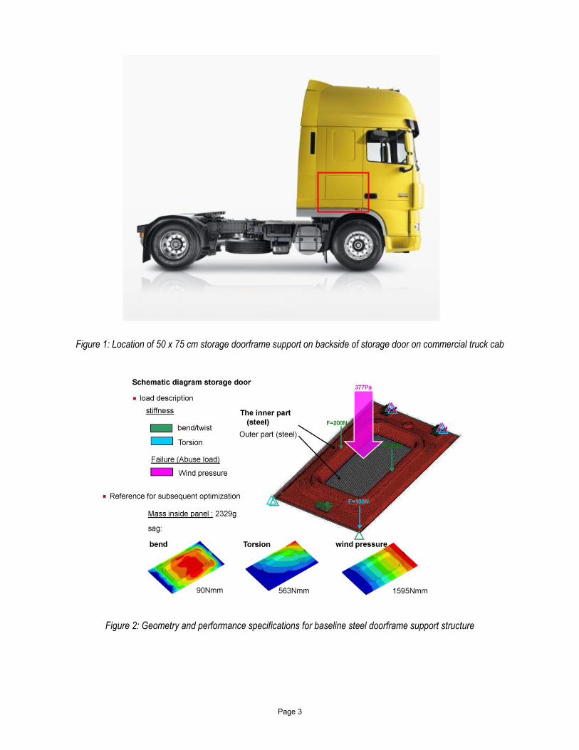
Figure 5: The addition of tabs in the four corners of the part was a minor modification made to the carryover design in order to facilitate movement of the laminate stack formed from the UD tapes as it was moved from station to station during processing. Several different configurations were evaluated with different layups. A design that was not used
is shown on the left (with tabs circled) and the final tab design is shown on the right.

Page 8
Part 2: Virtual Prototyping & Design Optimization
Much of the previous design geometry had been retained in the models of the part, although similar concessions were made again to ensure moldability (including keeping radii generous). One change that was made to the design was the addition of tabs in all four corners of the doorframe support that would be used as clamping points to move the laminate stack from one station to another during preheating / consolidation and molding and would be cut off during post-mold trimming operations. Researchers evaluated a number of different tab configurations experimentally to determine which option worked best. Two of those configurations (one that was used and one that was rejected) are shown in Figure 5.
Once material cards were developed for each material, iterative simulation work began on the carryover part geometry and performance requirements from the earlier lightweighting study. Using the reference geometry, analysts built new models representing possible ply orientation options for each of the three candidate materials. The layup was built successively in 10o steps (e.g. with the first layer at 90o, the second layer at 80o, etc.). Then, the software's "optimization solver" selected the layers that were most important for reaching the analysis goals. In the next step, the software decided how many layers for each orientation were required and what their position should be. In this way, the basic optimization model contained 21 layers. Similarly, quasi-isotropic models were built using orientations that ranged from -45o to +45o, also in 10o steps. The models were then used in a series of iterative structural analyses that simulated the key load cases (e.g. torsion, bending, and wind loading) previously identified as requirements for the part (Figure 2).
First, an isotropic simulation was conducted and then second, an anisotropic simulation was performed in order to optimize basic geometry (including thickness and part size), and sequence of ply layups for each material. Analyses looked at the effects of changing ply layups and fiber orientation combinations on predicted mechanical performance of the part. Results were compared back to properties previously obtained for the benchmark steel part to see if and how results changed. During these early iterations, the analysts were not trying to comply with the thickness restrictions of the tool; rather, like the later work on the organosheet study, they were trying to understand what was possible with the tape laminates and what tradeoffs in weight and thickness gave the best performance in the unoptimized geometry. The optimized
sequence was [0o,0o,+45o,-45o,+10o,-10o,90o]s, although this layup was never produced because
it would have been too thick to mold in the carryover tooling. Once the best possible options had been explored, it was time to modify the models in a third round of simulations in order to meet the actual constraints of the project ― namely the thickness limitations of the carryover tooling. This was accomplished by deleting all plies in each of the models that were judged not to make a significant contribution to molded part function. The analysts kept the ±10o plies, for example, since they improved bending stiffness; ±45o plies were retained because they were shown to add to torsional stiffness; surface plies with 0o orientation increased wind loading and bending performance; and bottom plies at 90o made it easier to handle and move the laminate stack. Other issues considered by the analysts were ensuring the part was moldable and that it would be visually acceptable to the OEM customer. Plies were paired for all layers except the top (0o) and bottom (90o) to achieve a balanced laminate that would not be subject to post-mold warpage. With non-essential plies removed from the model, the analyst reconfirmed that the part would meet the application requirements.

Page 9
Table III: Performance predicted for baseline steel and PPGF70 composite with steel skins in place†
Property Steel (Baseline) PPGF70 Change
Torsional elasticity (Nmm) 563.8 524.6 -7
Windload elasticity (Nmm) 1,594.7 487.1 -69.5
Mass (kg) 5.66 5.26 -0.4 Thickness (mm) 0.9 3.51 +2.61
† Compliance as energy to evaluate stiffness. Reduction of this value shows a stiffness increase.
With results available for all three candidate materials indicating that mass would be
reduced and performance would be increased, the research team now decided to focus the rest of the study on the more economical and lighter PPGF70 grade, which they felt would be of greater interest to both commercial truck and automotive OEMs. Since thermal requirements for the part were not high, the PP matrix would provide sufficient performance. Last, the final 8-ply
schedule of [0o,10o,-10o, 90o, 90o,-10o,10o, 0o] was passed to ICT to begin the process study. The predicted mass was 1.92 kg in laminate composite vs. 2.33 kg for the baseline steel part and predicted thickness was 2.16 mm in composite (0.27 mm/ply) vs. 0.9 mm for steel. Other performance predictions from this final iteration are shown in Table III, which included estimates with the steel skins in place. Torsional elasticity improved a small amount, but wind-load elasticity was significantly better in the composite models. Given that the analysis goals this time were essentially the same as in the earlier organosheet study ― to reduce mass and maintain or improve performance under the geometry and loading required ― researchers felt that this part of the project had been a success.
Part 3: Process Characterization & Optimization
The last major phase of the lightweighting study began with molding studies conducted on full-size doorframe support parts to better understand how the material behaved in the compression-molding process, and eventually moved to process optimization to reduce cycle time in order to prove scalability for the commercial truck or automotive industries.
During the period when EDAG was using virtual prototyping tools to optimize part design and ply layup, ICT researchers were molding and testing materials for materials characterization and working on the equipment and process flow that would be used to produce the full-size doorframe parts. First, some minor modifications were made to the heating system on the carryover aluminum tool in which the parts would be molded. Second, the team prepared a machine5 that would be used for automatic layup of the thermoplastic composite tape plies. The RELAY system was specifically developed for use with thermoplastic composite tapes (reinforced with glass or carbon fiber and in widths ranging from 50 to 150 mm). As such, it offers high-speed, very-accurate and repeatable production of thermoplastic composite laminates. Tapes are fed into the equipment from cardboard spools whose inner diameter is ≈152 mm and whose outer diameter is ≈300 mm.
5 Called RELAY, the equipment was developed by Fiberforge and has since become the intellectual property of Dieffenbacher
GmbH Maschinen- und Anlagenbau (http://www.dieffenbacher.de/index.php?id=1&L=1).
Page 10
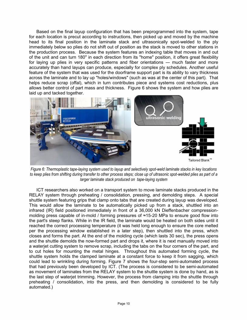
Based on the final layup configuration that has been preprogrammed into the system, tape for each location is precut according to instructions, then picked up and moved by the machine head to its final position in the laminate stack and ultrasonically spot-welded to the ply immediately below so plies do not shift out of position as the stack is moved to other stations in the production process. Because the system features an indexing table that moves in and out of the unit and can turn 180o in each direction from its "home" position, it offers great flexibility for laying up plies in very specific patterns and fiber orientations ― much faster and more accurately than hand layups can produce, especially for complex ply schedules. Another useful feature of the system that was used for the doorframe support part is its ability to vary thickness across the laminate and to lay up "holes/windows" (such as was at the center of this part). That helps reduce scrap (offal), which in turn contributes piece and systems cost reductions, plus allows better control of part mass and thickness. Figure 6 shows the system and how plies are laid up and tacked together.
Figure 6: Thermoplastic tape-laying system used to layup and selectively spot-weld laminate stacks in key locations to keep plies from shifting during transfer to other process steps; close up of ultrasonic spot-welded plies as part of a
larger laminate stack produced on tape-laying system
ICT researchers also worked on a transport system to move laminate stacks produced in the RELAY system through preheating / consolidation, pressing, and demolding steps. A special shuttle system featuring grips that clamp onto tabs that are created during layup was developed. This would allow the laminate to be automatically picked up from a stack, shuttled into an infrared (IR) field positioned immediately in front of a 36,000 kN Dieffenbacher compression-molding press capable of in-mold / forming pressures of ≈15-20 MPa to ensure good flow into the part's steep flanks. While in the IR field, the laminate would be heated on both sides until it reached the correct processing temperature (it was held long enough to ensure the core melted per the processing window established in a later step), then shuttled into the press, which closes and forms the part. At the end of the molding cycle (which lasts 30 sec), the press opens and the shuttle demolds the now-formed part and drops it, where it is next manually moved into a waterjet cutting system to remove scrap, including the tabs on the four corners of the part, and to cut holes for mounting the metal hinges. Throughout this automated forming cycle, the shuttle system holds the clamped laminate at a constant force to keep it from sagging, which could lead to wrinkling during forming. Figure 7 shows the four-step semi-automated process that had previously been developed by ICT. (The process is considered to be semi-automated as movement of laminates from the RELAY system to the shuttle system is done by hand, as is the last step of waterjet trimming. However, the process from clamping into the shuttle through preheating / consolidation, into the press, and then demolding is considered to be fully automated.)

Page 11
Once the production process flow was defined and the equipment built or prepped, and with the ply schedule in hand, ICT began a novel process study to better understand how the thermoplastic tapes behaved in the project's tool and molding process. There were four major parts to the process study: in the first part, a draping study with three specific layups was conducted; in the second part, parts laid up according to the schedule developed by EDAG were molded, then sectioned (cut) and examined under a light microscope; in the third part, more parts were laid up, thermocouples were inserted, and parts were heated and molded at different temperatures and times to develop a process window for that particular material; and in the fourth part of the process study, work was done to fine-tune the process sequence to reduce cycle time.
Figures 7: Four-step production process to produce doorframe support (top row) as well as what the material looks like as it proceeds through the production process (bottom row). Process begins with automated layup of laminate
stack on RELAY system. Stack is manually moved to the shuttle system, where it is clamped and automatically moved first into the infrared field in front of the compression press for preheating; then shuttled into the press, which closes and molds the part in 30 sec; the press then opens and the formed part is next demolded automatically; in the
last step the part is manually moved to a waterjet cutter where it is trimmed and prepped for final assembly.
Page 12
Laminate Draping Study
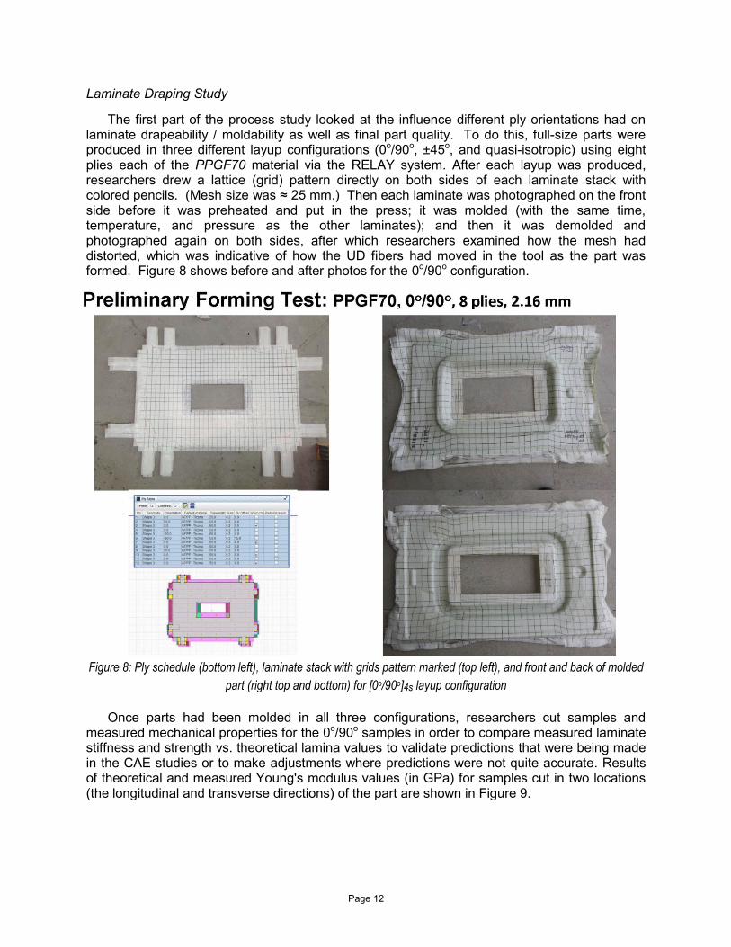
The first part of the process study looked at the influence different ply orientations had on laminate drapeability / moldability as well as final part quality. To do this, full-size parts were produced in three different layup configurations (0o/90o, ±45o, and quasi-isotropic) using eight plies each of the PPGF70 material via the RELAY system. After each layup was produced, researchers drew a lattice (grid) pattern directly on both sides of each laminate stack with colored pencils. (Mesh size was ≈ 25 mm.) Then each laminate was photographed on the front side before it was preheated and put in the press; it was molded (with the same time, temperature, and pressure as the other laminates); and then it was demolded and photographed again on both sides, after which researchers examined how the mesh had distorted, which was indicative of how the UD fibers had moved in the tool as the part was formed. Figure 8 shows before and after photos for the 0o/90o configuration.
Figure 8: Ply schedule (bottom left), laminate stack with grids pattern marked (top left), and front and back of molded
part (right top and bottom) for [0o/90o]4s layup configuration
Once parts had been molded in all three configurations, researchers cut samples and
measured mechanical properties for the 0o/90o samples in order to compare measured laminate stiffness and strength vs. theoretical lamina values to validate predictions that were being made in the CAE studies or to make adjustments where predictions were not quite accurate. Results of theoretical and measured Young's modulus values (in GPa) for samples cut in two locations (the longitudinal and transverse directions) of the part are shown in Figure 9.

Page 13
Figure 9: Cross-section of doorframe support showing significant thickness variations across the finished part, which were the result of mold restrictions
Initial results showed the laminate provided good draping behavior, even in sections of the
part that featured complex sequences of concave and convex shape changes (Figure 10). By comparing before and after photos of grid patterns on the various parts, it was relatively easy to visualize how plies moved (due to interply slippage) and how fiber bundles were reoriented across the length and width of the part. This, in turn, helped them better understand how local geometry affected initial layup configurations.
Last, this preliminary draping study also allowed researchers to check equipment settings and to verity that each orientation was indeed possible to mold in the demonstrator-part geometry. This preliminary molding trial also gave them the opportunity to verify that preheating parameters, handling time, molding pressure, and surface aesthetics.
Figure 10: Cross-section of doorframe support showing significant thickness variations across the finished part, which were the result of mold restrictions

Page 14
Figure 11: Digitally "stitched" micrographs of molded part in cross-section showing matrix and fiber movement in areas with different thickness profiles
Light Microscopy Study
Next, researchers returned to the [0o/90o]4s ply schedule and molded additional full-size
doorframe support parts in PPGF70. These parts were then sectioned (cut into long, thin strips) via waterjet so pieces that were approximately 200 mm in length and 2 mm in width were obtained. Next, these long, thin strips were placed under a light microscope and each section of each strip was examined and then photographed. In this step, researchers observed how fibers moved across the part. They also looked for indications of poor consolidation during the preheating step, such as if fibers had twisted or broken (particularly in areas with radii, thickness changes, or concave/convex transitions), and they looked for resin-rich areas, dry spots, and visible voids. Because none of these defects were found, this microscopy study helped verify that they had achieved good consolidation across an individual part (particularly in critical areas like radii) as well as between multiple molded parts. That, in turn, helped give them confidence that they could achieve consistent laminate quality and that the automated layup, preheating, and molding steps were indeed reproducible.
Once the strip was examined carefully and each section was photographed, the images were digitally "stitched together" in a single image in order to give researchers a better sense of local vs. global fiber movements (one example of which is shown in Figure 11). Another benefit this microscopy study brought to the project was that it helped researchers better understand how material squeeze-flowed into specific sections of the tool with mold restrictions. Because the tool had been designed to reproduce geometry found in the benchmarked steel part, and that part had a nominal wall of 0.9 mm (even in steep flanks), the laminate stack (which was ≈ 2.16 mm going into the tool) became compacted in some areas of the tool. In spite of these less than ideal molding conditions, the laminate proved quite tolerant of local pressure fluctuations during molding and handled thickness transitions without fiber breakage ― a situation that otherwise could have compromised the final part's mechanical performance.
Page 15
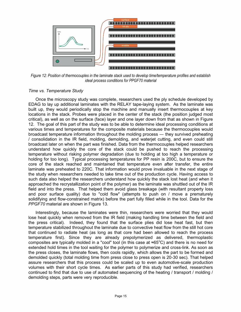
Figure 12: Position of thermocouples in the laminate stack used to develop time/temperature profiles and establish ideal process conditions for PPGF70 material
Time vs. Temperature Study
Once the microscopy study was complete, researchers used the ply schedule developed by EDAG to lay up additional laminates with the RELAY tape-laying system. As the laminate was built up, they would periodically stop the machine and manually insert thermocouples at key locations in the stack. Probes were placed in the center of the stack (the position judged most critical), as well as on the surface (face) layer and one layer down from that as shown in Figure 12. The goal of this part of the study was to be able to determine ideal processing conditions at various times and temperatures for the composite materials because the thermocouples would broadcast temperature information throughout the molding process ― they survived preheating / consolidation in the IR field, molding, demolding, and waterjet cutting, and even could still broadcast later on when the part was finished. Data from the thermocouples helped researchers understand how quickly the core of the stack could be pushed to reach the processing temperature without risking polymer degradation (due to holding at too high a temperature or holding for too long). Typical processing temperatures for PP resin is 200C, but to ensure the core of the stack reached and maintained that temperature even after transfer, the entire laminate was preheated to 220C. That information would prove invaluable in the next stage of the study when researchers needed to take time out of the production cycle. Having access to such data also helped the researchers understand how quickly the stack lost heat (and when it approached the recrystallization point of the polymer) as the laminate was shuttled out of the IR field and into the press. That helped them avoid glass breakage (with resultant property loss and poor surface quality) due to "cold flow" (attempts to push on / move a prematurely solidifying and flow-constrained matrix) before the part fully filled while in the tool. Data for the PPGF70 material are shown in Figure 13.
Interestingly, because the laminates were thin, researchers were worried that they would lose heat quickly when removed from the IR field (making handling time between the field and the press critical). Indeed, they found that the surface plies did lose heat fast, but then temperature stabilized throughout the laminate due to convective heat flow from the still hot core that continued to radiate heat (as long as that core had been allowed to reach the process temperature first). Since they are already prepolymerized as delivered, thermoplastic composites are typically molded in a "cool" tool (in this case at ≈65oC) and there is no need for extended hold times in the tool waiting for the polymer to polymerize and cross-link. As soon as the press closes, the laminate flows, then cools rapidly, which allows the part to be formed and demolded quickly (total molding time from press close to press open is 20-30 sec). That helped assure researchers that this process could be scaled up to even automotive-scale production volumes with their short cycle times. As earlier parts of this study had verified, researchers continued to find that due to use of automated sequencing of the heating / transport / molding / demolding steps, parts were very reproducible.

Page 16
Figures 13: Process window (defined as time vs. temperature) for PPGF70 laminate Process Optimization
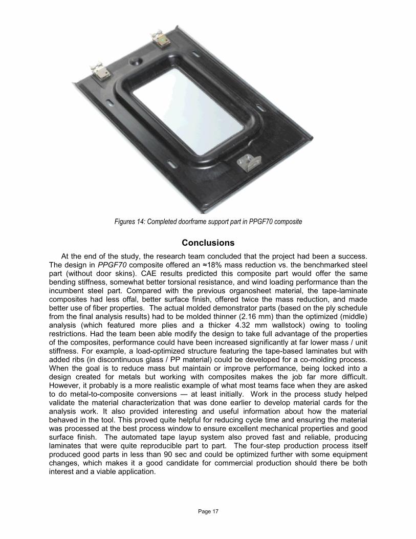
The last stage of the research program involved putting information learned in the earlier process study to work to optimize the production process in order to produce good parts as quickly as possible. For example, researchers studied the process window for the PPGF70 material in order to make in situ power adjustments to the IR field to optimize the heat cycle without over- or under-heating the laminate. Additional online monitoring of laminate surface temperature via pyrometers also provided useful feedback for trimming time out of the molding process. The goal had been to have the preheating / consolidation / molding / demolding portion of the production cycle be 90 sec or less and that was achieved, with the press portion of the cycle taking just 20 sec. Researchers felt part of the success came from the fact that the RELAY system could ultrasonically tack the laminate plies together during layup, which made handling easier and faster and contributed significantly to part-to-part consistency, since plies were prevented from shifting out of position prematurely. Since preheating proved the rate-limiting step in the process, researchers feel there are setups and concepts that could be explored to reduce cycle time further. Figure 14 shows the final part with mounting hardware installed.
Page 17
Figures 14: Completed doorframe support part in PPGF70 composite
Conclusions
At the end of the study, the research team concluded that the project had been a success. The design in PPGF70 composite offered an ≈18% mass reduction vs. the benchmarked steel part (without door skins). CAE results predicted this composite part would offer the same bending stiffness, somewhat better torsional resistance, and wind loading performance than the incumbent steel part. Compared with the previous organosheet material, the tape-laminate composites had less offal, better surface finish, offered twice the mass reduction, and made better use of fiber properties. The actual molded demonstrator parts (based on the ply schedule from the final analysis results) had to be molded thinner (2.16 mm) than the optimized (middle) analysis (which featured more plies and a thicker 4.32 mm wallstock) owing to tooling restrictions. Had the team been able modify the design to take full advantage of the properties of the composites, performance could have been increased significantly at far lower mass / unit stiffness. For example, a load-optimized structure featuring the tape-based laminates but with added ribs (in discontinuous glass / PP material) could be developed for a co-molding process. When the goal is to reduce mass but maintain or improve performance, being locked into a design created for metals but working with composites makes the job far more difficult. However, it probably is a more realistic example of what most teams face when they are asked to do metal-to-composite conversions ― at least initially. Work in the process study helped validate the material characterization that was done earlier to develop material cards for the analysis work. It also provided interesting and useful information about how the material behaved in the tool. This proved quite helpful for reducing cycle time and ensuring the material was processed at the best process window to ensure excellent mechanical properties and good surface finish. The automated tape layup system also proved fast and reliable, producing laminates that were quite reproducible part to part. The four-step production process itself produced good parts in less than 90 sec and could be optimized further with some equipment changes, which makes it a good candidate for commercial production should there be both interest and a viable application.
Page 18
Acknowledgements
The authors would like to thank other research engineers from ICT involved in the studies: Dipl.-Ing. Benjamin Hangs and M.-Eng. Felix Manger, as well as the ICT Polymer Engineering Department Leader, Prof. Dr.-Ing. Frank Henning.
Bibliography
1. Schneider, E., E. Preis, and J. Hülsmann, Herausforderungen bei der Berechnung und Optimierung mit Faserverbundwerkstoffen (Challenges in Calculation and Optimisation with Fibre-Reinforced Composites), Kunstoffe und Simulation 2012, Munich, Germany (April 23, 2012).
2. Emerson, D., Grauer, D., Hangs, B. Reif, M., Henning, F., Martsman, A., and Jespersen, S., Boosting Impact Strength of Thermoplastic Semi-Structural Composites in Horizontal Panels via Unidirectional Tape-Based Fabrics & Laminates, SAMPE Tech, Charlston, SC (Oct. 2012).
3. Emerson, D., Grauer, D., Hangs, B. Reif, M., Henning, F., Martsman, A., and Jespersen, S., Using Unidirectional Glass Tapes to Improve Impact Performance of Thermoplastic Composites in Automotive Applications, SPE ACCE, Troy (Detroit), MI USA, Sept. 2012.
4. Hangs, B., C. Esch, M. Reif, T. Huber, & F. Henning, “Integration of Features into Parts Made from Thermoplastic, Unidirectional Tape — Overview and Case Study,” SPE ACCE, Troy (Detroit), MI USA, Sept. 2011.
5. http://www.samsonrope.com/Documents/Technical%20Papers/TP_The%20Effect%20of%20Bending%20on%20the%20Tensile%20Strength%20of%20Statically%20Loaded%20Synthetic%20Ropes_March2011.pdf
6. http://www.iccm-central.org/Proceedings/ICCM17proceedings/Themes/Materials/3D%20TEXTILES%20&%20COMP/D1.2%20Sharp.pdf
7. Celanese (2014) Celstran® CFRT/LFRT Composites [Online]: http://www.celanese.com/engineered-materials/products/Celstran-CFRT.aspx