development of a development of a new new cold …
TRANSCRIPT

DEVELOPMENT OF A DEVELOPMENT OF A DEVELOPMENT OF A DEVELOPMENT OF A NEW NEW NEW NEW COLDCOLDCOLDCOLD----FORMED FORMED FORMED FORMED TRUSS SYSTEMTRUSS SYSTEMTRUSS SYSTEMTRUSS SYSTEM
Gábor Jakab*, László Dunai*, István Kotormán**
Fifth International Conference on Thin-Walled StructuresBrisbane, Australia, 2008
* Budapest University of Technology and Economics, Department of Structural Engineering
** Lindab Hungary Ltd.
BACKGROUND
R&D project with industrial background
Aim– Development of a truss system and design method– Verification/validation of the design method
Main characteristics of the system– Span: 12…24 meter
– Using only cold-formed C-sections– Flexible system allowing free design– Out-of-box solutions
5th ICTWS, Brisbane, Australia, 2008

STRUCTURAL ARRANGEMENT
Structural elements– Chord: two C-sections in back-to-back arrangement– Bracing: single C-sections, doubled at the supports
Structural joints– Eccentric bolted connections
5th ICTWS, Brisbane, Australia, 2008

STRUCTURAL ARRANGEMENT
5th ICTWS, Brisbane, Australia, 2008

5th ICTWS, Brisbane, Australia, 2008
Eccentricity– in-plane, out-of-plane
Load-bearing capacity, local stability behaviourRigidity, interaction with members
CHORDS+
BRACING
PROBLEM STATEMENT
JOINT}
?�Stability issues
– EC-based design
Similar problems solved

SOLUTION STRATEGY
Design method
DESIGN FE MODELLING
Globalmodel
EXPERIMENT
SAFETY
VerificationLocalmodel
Validation
Global structure
Design value
5th ICTWS, Brisbane, Australia, 2008

Global model – for design– 2-D beam model taking into account only in-plane
eccentricities– Used to determine the internal forces needed for design
FE MODELLING – BEAM MODEL
5th ICTWS, Brisbane, Australia, 2008

CHORD MEMBERS– Dominant mode: Interaction of flexural buckling and
biaxial bending
BRACE MEMBERS– Dominant mode: Compression and bending or interaction of
flexural buckling and bending about the weak axis
DESIGN METHOD – MEMBERS
11,
,
1,
,
1
≤⋅
⋅⋅+
⋅⋅
+⋅⋅ Mybzeff
yNEdz
Mybyeff
Edyy
Mybeffz
Ed
fW
eN
fW
M
fA
N
γκ
γκ
γχ
45.8% + 7.8% + 46.4% = 100%
5th ICTWS, Brisbane, Australia, 2008

DESIGN METHOD – JOINTS
BOLTED CONNECTION– Shear failure– Dominant mode: bearing failure
NO JOINT FAILURE MODES CONSIDERED
5th ICTWS, Brisbane, Australia, 2008

LABORATORY TESTING - SETUP
5th ICTWS, Brisbane, Australia, 2008

LABORATORY TESTING - SETUP
MEASUREMENTLoad via oil pressureStrains – strain gageDisplacements
5th ICTWS, Brisbane, Australia, 2008

Test 1failure in the upper chord, interaction of bending (weak axis) and flexural buckling
Load: 28,5 kN/jack
LABORATORY TESTING – FAILURE MODES
5th ICTWS, Brisbane, Australia, 2008

LABORATORY TESTING – FAILURE MODES
Test 2failure of the peak joint
Load: 35,5 kN/jack
New peak jointarrangement
5th ICTWS, Brisbane, Australia, 2008

Test 3failure of the upper chord (built-up section)
Load: 36,4 kN/jack
LABORATORY TESTING – FAILURE MODES
5th ICTWS, Brisbane, Australia, 2008

Test 4failure of a compression brace member;interaction of compression and bending
Load: 37,4 kN/jack
LABORATORY TESTING – FAILURE MODES
5th ICTWS, Brisbane, Australia, 2008
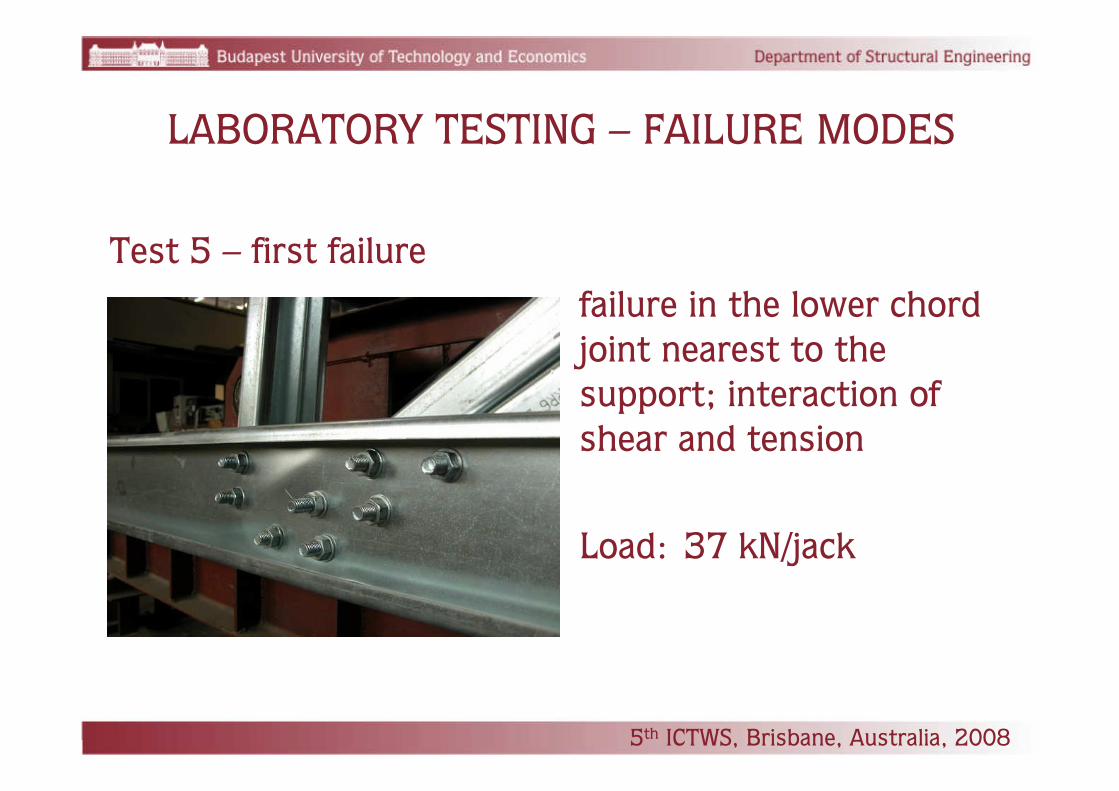
Test 5 – first failurefailure in the lower chord joint nearest to the support; interaction of shear and tension
Load: 37 kN/jack
LABORATORY TESTING – FAILURE MODES
5th ICTWS, Brisbane, Australia, 2008

Test 5 – final failurefailure of the upper chord; interaction of bending and flexural buckling
Load: 47,4 kN/jackULS load: 31.65 kN/jack
LABORATORY TESTING – FAILURE MODES
5th ICTWS, Brisbane, Australia, 2008

50,2046,97Brace
129,78137,96Lower chord
135,56144,76Upper chord
testFElevelAxial force [kN]ULS
LABORATORY TESTING – FE-MODEL
SLS level
The model is applicable for design
5th ICTWS, Brisbane, Australia, 2008

LABORATORY TESTING – DESIGN METHOD
Compression chord member failure mode identified– EC3 design rule modified based on strain measurement
15.0
1,1,
,
1
≤⋅
⋅⋅⋅+
⋅⋅
+⋅⋅ Mybzeff
spEdz
Mybyeff
Edyy
Mybeffz
Ed
fW
yN
fW
M
fA
N
γκ
γκ
γχ
Joint failure mode identified– EC3-based design formulae developed based on the
existing design method of N-type RHS-RHS joints
Brace member failure modes identified– EC3 design rule modified – calibrated – to ensure safety
level
5th ICTWS, Brisbane, Australia, 2008

AN EXAMPLE

Global FE surface model under development
Recently finished test series of cold-formed C sections with different end supports to study the truss members individually
DimTruss – a program to design these trusses –under development
FURTHER STEPS
5th ICTWS, Brisbane, Australia, 2008

Thank you for your attention!

Thank you for your attention!

• Global model – for development– Developed in ANSYS– 3-D beam model taking into account in-plane and out-
of-plane eccentricities– 6 DOF’s BEAM188 elements– Used to examine the
joint area using submodel-ling technique
FE MODELLING – BEAM MODEL No. 2

FE MODELLING – JOINT SURFACE MODEL
• Local model – for development– Developed in ANSYS– SHELL181, LINK10, BEAM4 elements– Kinematic load from beam
model Nr. 2– ~100k DOF’s– GMNIA

• CONTACT AREA, BOLTS
FE MODELLING – JOINT MODEL

• LOADS, MATERIAL PROPERTIES
FE MODELLING – JOINT MODEL

JOINT MODEL - RESULTS

Ultimate limit state (ULS)
JOINT MODEL - RESULTS

DESIGN METHOD – TENSION ELEMENTS
BRACE MEMBERS– Tension and bending about the weak axis– Plastic design resistance reduced
CHORD MEMBERS– Tension and biaxial bending
0, 6,0
M
ybgRdpl
fAN
γ⋅
⋅=
5th ICTWS, Brisbane, Australia, 2008