development of a compact and flexible deep drawing module
TRANSCRIPT

IN DEGREE PROJECT MECHANICAL ENGINEERING,SECOND CYCLE, 30 CREDITS
, STOCKHOLM SWEDEN 2015
Development of a compact and flexible deep drawing module for fast running paperboard forming machine
JOAKIM SIVBORG
KTH ROYAL INSTITUTE OF TECHNOLOGYSCHOOL OF ENGINEERING SCIENCES


Development of a compact and flexible deep drawing module for fast running
paperboard forming machine
Joakim Sivborg Degree project in Solid Mechanics
Second level, 30.0 HEC Stockholm, Sweden 2011
Abstract In collaboration between TU-Dresden and KTH, a new flexible forming unit as part of a larger high speed deep drawing machine has been developed. The development is based on the current laboratory test rig at TU-Dresden. The new module is a 1/12th part of a larger, high speed forming wheel. The module was developed to meet the requirements of an output above 700 cups/min. The module was developed to replace hydraulics with all electric actuators/drives. The module was developed to be compact and simple yet reliable and robust in design.
There is currently a patent application submitted in Germany for the new module, where the author is co-inventor.


Utveckling av en kompakt och flexibel arbetsmodul till en höghastighetsmaskin
för djupdragning av kartong
Joakim Sivborg Examensarbete i Hållfasthetslära
Avancerad nivå, 30 hp Stockholm, Sverige 2011
Sammanfattning I samarbete med Tekniska Universitetet Dresden har en ny flexible arbetsmodul till en djupdragningsmaskin för höghastighetsformning av kartong tagits fram genom djupdragning. Arbetet är baserat på befintlig teknik som finns i form av en pilotutrustning på Universitetet i Dresden. Den nya modulen är en 1/12:e del av en större höghastighetsmaskin i cirkulärt utförande. Modulen har utvecklats för att möta kraven på att producera 700 koppar/minut. Modulen är utvecklad att ersätta hydraulik med helt elektrisk drivning. Modulen är utvecklad för att vara enkel och snabb men samtidigt tillförlitlig och robust.
Det finns för närvarande en detaljerad patentansökan baserad på detta arbete som del av ett större systempatent för en höghastighetsmaskin med flera steg, där författaren är en av uppfinnarna.

Foreword The author wishes to thank Prof. Sören Östlund for providing the opportunity to go to Dresden and conduct the master thesis and Dr. Ing. Marek Hauptmann for kindly accepting me as a student and excellent guidance for the work at TU Dresden. Dr. Ing. Hauptmann is also co-inventor for the patent application.

Contents Introduction-Project definition ........................................................................................ 1
Literature study ................................................................................................................ 2
Experiments to determine machine specifications ........................................................ 15
The design space ............................................................................................................ 19
Mechanical function and motion design of tools ........................................................... 20
Summary ......................................................................................................................... 27
Conceptual design work ................................................................................................. 28
Choice from the conceptual work .................................................................................. 37
Design of drives, including reliability analysis ................................................................ 42
Machine design ............................................................................................................... 46
The final concept ............................................................................................................ 56
The Global Machine ........................................................................................................ 59
Conclusion ...................................................................................................................... 61
Acknowledgements ........................................................................................................ 63
Recommendations for further work .............................................................................. 62
References: ..................................................................................................................... 64
Appendix A - Calculations ............................................................................................... 66
Appendix B – Simulation results ..................................................................................... 67
Appendix C – CAD Drawings ........................................................................................... 71
Appendix C – Patent information ................................................................................... 80
1
Introduction-Project definition Field of thesis: Processing Machines and Processing Technology
Name of student: Joakim Sivborg
Host at TU Dresden: Dr. Ing. Marek Hauptmann
Examiner at KTH: Prof. Sören Östlund
Title: Development of a compact and flexible deep drawing module for fast running paperboard forming machine.
Objectives The 3D forming of paperboard especially deep drawing, has recently gained attention in laboratory scale and seems to be very suitable for several packaging applications. Therefore the realization of technological approaches in high speed packaging machinery is a new challenge.
The aim of the present work is to redesign a laboratory deep drawing unit for paperboard as the core unit of a continuous running packaging machine working with parallel rotary moving tools and an intended output of 800 pieces per minute. Based on a detailed literature research on deep drawing techniques and continuous working packaging machinery a specification for the construction was generated. With the help of the specification principles, the adaptation of the technology to the conditions in such machinery should be worked out and discussed by relevant criteria. The preferred type is to be designed in detail including mechanical function, choice and dimensioning of drives, motion design of tools and proof on reliability, stiffness, accuracy and dynamic behaviour (vibrations) for the crucial parts.
In addition a feeding unit applying the blank to the forming unit shall be developed. The final technical concept shall be used to generate requirements to the design of the rotary table.
In addition a concept for a feeding unit applying the paperboard blank in a continuous way to the forming unit is to be developed by considering different feeding principles and discussing them with regard to accuracy and reliability of the blank positioning. The preferred concept should be designed in detail. The documentation should include all technical documents needed for manufacturing.

2
Literature study Three dimensional forming is a key future process for advanced shaping of sustainable materials like paperboard and paper based product [1]. However, until the present day the application of the deep drawing process, which has been known for the past 50 years, has not been a viable way of shaping paperboard products. There are many reasons for this. These include the sensitivity of the material and the large number of failure mechanisms. Despite this the process has great potential to easily, cheaply and quickly form paper products into advanced structures in one or two sweeps. The work carried out jointly by TU Dresden [1,2] and KTH aims to investigate and understand the physics of the paper and the deep drawing process applied to paper.
In order for paper to be applicable in future packaging it has to meet several requirements. For instance the product has to have a desirable surface texture. It has to look clean (no draw marks) and no decolourization. Furthermore the material has to be able to be formed and incorporate a gas tight seal for use in the food packaging industry. However, the potential of deep drawn paper products are limitless.
The process of deep drawing Deep drawing of paper is the process in which a paper blank is placed over a female mould cavity of desired shape. The blank is then clamped by a blank holder and a male punch/ die is extended through the cavity which draws, folds and forms the blank into the desired shape. The process is most common today in metals where it is extensively used in the automotive industry to create special shapes very quickly and easily. Figure 1 illustrates the deep drawing process in 4 steps.
Figure 1: Schematic of the deep drawing process [1]
Today there exist several technologies which are very similar to deep drawing. Here, deep drawing is defined by the process described above and illustrated in Figure 1. Furthermore, there are two similar processes; hydroforming and press moulding. Both methods extend a male punch or die into a female finite and closed counterpart mould. The press moulding has a solid die and forms the product. In hydroforming liquid pressure inflates a membrane which fills out the mould and forms the blank.

3
Differences between deep drawing of paper and metals For metals the process of deep drawing is well known and well documented as it has been applied in industry for many years. However, the idea of applying it to paperboard products has also been know but due to its limitations, has not been frequently used until recently. The formability of sheet metal is good. A sheet of ductile metal can be very easily stretched and the deformation mechanisms are well understood. Paper behaves very differently from metals. While many metals can be assumed to be close to isotropic, paper is highly anisotropic. In paper three principal material directions are defined; the Machine Direction, MD, Cross machine Direction, CD and the through thickness Z Direction, ZD [3], as illustrated in Figure 2.
Figure 2: The principal material directions defined for paper [2]
Since paper is a fibrous composite material its directional strength varies significantly. Table 1 illustrates some typical values of paper materials [3].

4
Table 1: Directional material properties of paper [3]
An example of this is the fact that experiments with a paper which is placed in a uniaxial tensile test and pulled until breakage can be seen to elongate ~3%. However, in the deep drawing process this number approaches ~15%. This is significantly larger and why this happens it is not known. However this is one of the reasons that deep drawing is viable and able to form shapes with good quality.
5
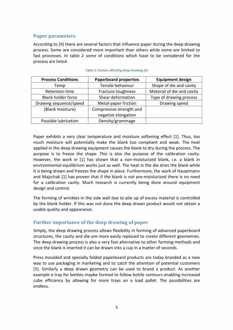
Paper parameters According to [4] there are several factors that influence paper during the deep drawing process. Some are considered more important than others while some are limited to fast processes. In table 2 some of conditions which have to be considered for the process are listed.
Table 2: Factors affecting deep drawing [4]
Process Conditions Paperboard properties Equipment design Temp Tensile behaviour Shape of die and cavity
Retention time Fracture toughness Material of die and cavity Blank holder force Shear deformation Type of drawing process
Drawing sequence/speed Metal-paper friction Drawing speed (Blank moisture) Compressive strength and
negative elongation
Possible lubrication Density/grammage
Paper exhibits a very clear temperature and moisture softening effect [1]. Thus, too much moisture will potentially make the blank too compliant and weak. The heat applied in the deep drawing equipment causes the blank to dry during the process. The purpose is to freeze the shape. This is also the purpose of the calibration cavity. However, the work in [1] has shown that a non-moisturized blank, i.e. a blank in environmental equilibrium works just as well. The heat in the die dries the blank while it is being drawn and freezes the shape in place. Furthermore, the work of Hauptmann and Majschak [1] has proven that if the blank is not pre-moisturized there is no need for a calibration cavity. Much research is currently being done around equipment design and control.
The forming of wrinkles in the side wall due to pile up of excess material is controlled by the blank holder. If this was not done the deep drawn product would not obtain a usable quality and appearance.
Further importance of the deep drawing of paper Simply, the deep drawing process allows flexibility in forming of advanced paperboard structures, the cavity and die are more easily replaced to create different geometries. The deep drawing process is also a very fast alternative to other forming methods and once the blank is inserted it can be drawn into a cup in a matter of seconds.
Press moulded and specially folded paperboard products are today branded as a new way to use packaging in marketing and to catch the attention of potential customers [5]. Similarly a deep drawn geometry can be used to brand a product. As another example a tray for bottles maybe formed to follow bottle contours enabling increased cube efficiency by allowing for more trays on a load pallet. The possibilities are endless.

6
Technology Today’s technology for deep drawing of paper is still in its infancy and the only real machine where research is done is the laboratory test rig at TU Dresden, Saxony, Germany.
Prior art and patent search In order to accurately determine the state of the previous and current technology in the working area, a patent search is carried. The terms included in the search are; paper, paperboard and deep drawing. It is is expected to turn up very few results in this search and more time will be spent on the research of drive technology in the next section.
In order to research the area of paper and paperboard deep drawing, a patent search via ESPACENET was been carried out to find the state of the art and any prior technology which may be of importance. Similar to searching for articles in a publication database a search among patents is very important.
In order to simplify future work and future research into this area, it is of great interest and it can be of great use to state that the CPC (Common Patent classification Class) is of Main Category B-Shaping, B29-Plastic shaping’s. Furthermore, a more detailed class can also be stated; B29C2791- Plastic Shaping in general. Moreover, in IPC (International Patent Classification) category the subject falls under B65D1/00 which is the moulding of pulp material in a system of machines.
In this patent search 6 objects were found. Not all of these 6 patents are of direct relevance.
The first patent [A] deemed to be of importance is an application by Stora Enso OY, Finland. The embodiment of the invention describes a method for forming paper board products such as to avoid wrinkling, breakage and incorrect shapes. The invention would achieve this by forming in several steps. Each system is done in four steps, where three are forming steps. However, the die is a three part system that extends into a female counter part. The female counterpart is shown to be a solid mould. Based on the drawings and the descriptions this system is not of the same category as a through cavity deep drawing. In such case this invention is more a press moulding technology and should belong in that category, not deep drawing.
A second patent [B] relates to a method to avoid creasing and to make the lips of a cup smooth enough for a gas tight seal. This work is similar to the experimental work of Hauptmann and Majschak [1,2].
Thirdly, a patent application [C] relating to an inline machine concept where a roll of paperboard is fed into a machine which pre-treats the blank then cuts it, followed by a deep drawing step and one or several forming steps. This invention is irrelevant to the
7
present work as it suggests a pre-moistening of the blank which is not to be used here. The machine is also an inline configuration and would require several units in parallel to achieve any significant volume output. This is not feasible.
The other three patents relates to the making of the paperboard itself. This is not of any interest this project, but more so once a laboratory scale machine is manufactured.
Furthermore, to extend the patent search, the subject of paper moulding was also investigated. The machines that are the state of the art here are all discontinuous step systems. All these paper moulding machines either use press moulding or a similar method. However, it appears as if the term deep drawing is being loosely used for systems which appear to be more of a press moulding type.
State of the art of continuous high speed machinery The state of the art in high speed machinery that have a continuous working principle appears clearly in the food process and packaging industry. For instance, there are several companies which solely focus on a high speed packaging solution that works on the continuous principle and has a very high output. The food process and packaging industry is of greatest interest for several reasons since the food industry have to operate against extremely strict hygiene and contamination standards. The food industry has a low margin and wants to maximise production. Hence, technology needs to have a very high accuracy and reliability. The industry is well advanced, but it is not yet matured indicating further innovation and development work and hence interest in new technologies.
Packaging An example of a company that make machines with very high output is Theegarten Pactec [9]. For instance Theegarten Pactec has a machine technology which is of great interest, namely a rotating wrapping technology to double twist wrap classic candy. This machine has an output of 2300 pieces/min [9] and it works with a continuous principle proving that the technology is possible. This technology packages the candy and produces the packaging in the same cycle.
Packaging container production For the food industry it is imperative that a reliable, clean and cheap system is available for the manufacture of less trivial packages like candy wraps, for instance plastic bottles. The principle of producing plastic bottles is simple and straight forward. Melted PET plastic is extruded into moulds and then blown by air to expand and fit the mould. The most commonly occurring technology does this in step wise production [11]. However, systems for continuous blow moulding are available. These system work according to the principle of a rotary wheel with several moulds as illustrated in Figure 3.

8
Figure 3: Rotary blow moulding of plastic [11]
The company Techne Spa has taken this principle to a new level with its ROTAX® machine [13]. This machine has 24 dual parison moulds on a large vertically orientated wheel. The machine is able to make 30 000 bottles/hour of 250 ml size. Small bottles are made neck to neck. This machine can also simply change the moulds to make other bottles like 1, 2 and 5 litres sizes. The output capacity is naturally limited by the cooling and solidification time of the plastic in the moulds. If this happened instantly or within 1 to 2 seconds the machine could have a higher output.
Drive technology
The state of the art technology in paper deep drawing machines, like the test rig available at TU Dresden is a hydraulic system. The idea here is to replace this system as it has some obvious disadvantages like cleanliness, maintenance speed and noise to a modern all-electric drive system.
Firstly, in order to design a high output continuous process deep drawing machine there are some factors and problems given have to be taken into account and solved. As stated in the problem formulation, the removal of the hydraulic drive system is one such requirement.
Today’s problem Beside the use of a hydraulic system there are today several other problems. For instance, the system that is being used today does not allow for a smaller blank holder force than 500 N. In an all-electric servo drive system there is a need to provide a method for implementing a force control of the system to the drives. This sounds more straight-forward than it is. Tests using a second laboratory test rig at TU Dresden experimenting with force control have proven inaccurate.
9
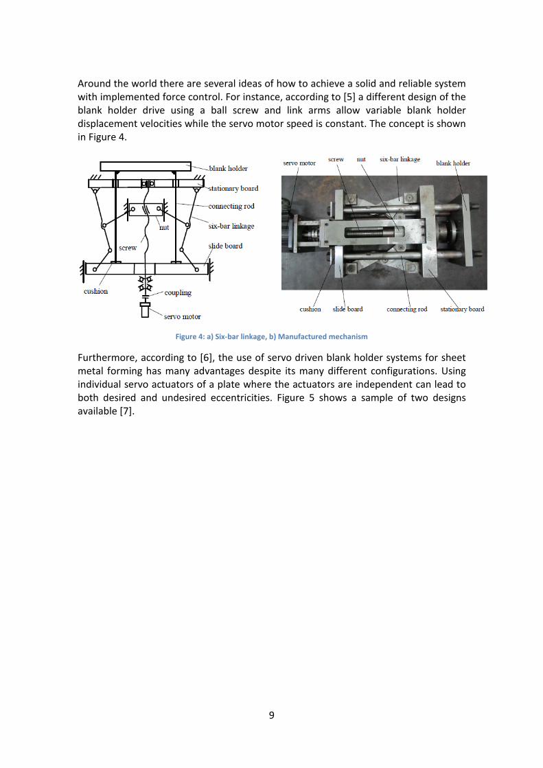
Around the world there are several ideas of how to achieve a solid and reliable system with implemented force control. For instance, according to [5] a different design of the blank holder drive using a ball screw and link arms allow variable blank holder displacement velocities while the servo motor speed is constant. The concept is shown in Figure 4.
Figure 4: a) Six-bar linkage, b) Manufactured mechanism
Furthermore, according to [6], the use of servo driven blank holder systems for sheet metal forming has many advantages despite its many different configurations. Using individual servo actuators of a plate where the actuators are independent can lead to both desired and undesired eccentricities. Figure 5 shows a sample of two designs available [7].

10
Figure 5: Different types of servo driven presses
Based on [5,6,7], to name but a few, the use of servo driven actuators for blank holders in sheet metal forming and deep drawing applications has proven viable and even simple servos are able to drive high force requirement actuators. Furthermore, a construction using linkages as shown in [6] allows for variable blank holder speeds while servo speeds are constant. Using simple inexpensive sensors the system is able to achieve a stable force control feedback to the blank holder, which previously has been difficult and problematic.
Force control of servo technology The need to control the electric servo motors of an electric servo driven system is apparent. However, the simplest technology would be to use a position control, yet this is not possible. The need for the servos to be controlled with a force control method and the ability to adjust the servos to exert a certain force for the deep drawing process is imperative. The current technology of paperboard deep drawing does not allow a blank holder force lower than 500 N.
However, the use of force controlled servos is not as straight-forward as it may seem. Firstly a good feedback based control model needs to be designed. There are several methods available. One such method is to use an analogue force sensor in the blank

11
holder to measure the force exerted by the blank holder and from there control it to follow a desired increase or decrease pattern [6].
The need to control electric servo technology with force control and force control feedback is becoming more and more important, especially with the increased use of robotics and interactions with their environment [13]. Hence the technology is of great interest for the future and much research is being carried out.
Material testing equipment Yet, despite all the problems mentioned in the previous text, there is available technology which satisfies the requirements of accurate force control, repeatability and good machine life span. This technology is to be found in material testing equipments from manufacturers i.e. Instron or MTS, Zwick and many others. Modern material testing machines for smaller force requirements are usually of an electromechanical design. Most of these machines use a screw type actuator system where the applied force is controlled via the load cell. Figure 6 illustrates one example of an electro mechanically actuated material testing machine [15], its drive and actuation system. This system is able to be controlled via load (force), elongation and displacement. The system uses a single re-circulating balls screw mechanism. Similar technology is used in the second deep-drawing test rig at TU Dresden.

12
Figure 6: Electro mechanical testing machine [15]
Yet, there are also two other types of drive and actuation systems used in electromechanical material testing machines. The second type is a double circulating call screw mechanism [16], discussed below.

13
Figure 7: Double balls crew mechanism. EX 1-3 shows different sensors for control of the system [15]
The third type of system is the linear actuator. This system is an electromechanically driven version of a hydraulic piston. The technology is wide spread today and is being used to replace hydraulics in areas where the use of high pressure fluid is undesirable [18,19]. A linear actuator can be designed according to several different principles. The most efficient and modern system uses planetary screws and an electric motor either mounted in series, parallel or around the planetary screws. One example is shown in Figure 8.

14
Figure 8: Cut away of a linear actuator [20]
Furthermore, the application of electromechanically actuated servo drives is also available for use in material fatigue testing machines [17]. The use of this technology for a cycle of high loading and unloading suggests that it is suitable for use also within the present application.
Initial force control investigations The principle of force control can be achieved in two ways. The first is an open loop where the motor current is measured and this is related to the torque of the servo motor. Due to manufacturing irregularities and the uncertainty for the torque constant value (motor constant which varies greatly in all individual motors), electromechanical linear actuators have a 10 % error when using this type of method. On the other hand the second method is known as closed loop force control. This allows for the use of external sensors like a force sensor or similar devices to measure the force and relay the data for adjustment back to the control software.
Conclusions based on the literature study Based on the above critical literature survey, it is possible to build an all-electric, high speed machine for paper deep drawing to be implemented into a new high speed continuous working machine.
The new high speed machine should be designed along the principle of continuous working output and not a step wise principle. The most space efficient setup is to use a rotary principle similar to that of the Technee Spa ROTAX® machine [13].

15
Experiments to determine machine specifications
Aim The aim of the experiments was to determine the specifications and limitations for the new high speed deep drawing machine. In order to do this several types of papers with varying machine parameters were tested.
From the experimental results a specification list was generated. This list was the basis against which a new forming unit as part of a high speed machine was designed.
The machine parameters tested were:
Blank holder force Punch velocity profile Punch acceleration profile Material type
The different papers that was used in these experiments were; StoraEnso Trayforma 300 and Trayforma 350, Mayernmelnhof P350 and Iggesund 300. The numbers are the grammage of the paperboards. The idea was to test the reliability of the different materials on a simple basis, i.e. if they can be formed using the same tool even the optimal conditions are not met.
The velocity profile of the punch was set or prescribed in the control software in two steps. First an initial distance, usually 5 mm and an initial velocity was set. The distance is variable up to 50 mm. Then in the rest of the cavity distance, totally 60 mm, the velocity was prescribed. Using a combination of these two steps, the maximum possible speed will be investigated.
The maximum usable blank holder force was also determined. It is known from the work of Hauptmann and Majschak [1,2] that a higher blank holder force increases quality, i.e. it compresses the wrinkles due to the material overflow. However, there are practical limits and these were investigated. Also it was investigated how the maximum blank holder force is related to the maximum velocity allowed.
Furthermore, as is known the blank holder force is decreased linearly once the process is started [24]. To investigate this, the linearly decreasing blank holder force will be interrupted with a deviation in the decrease profile to test if this affects the material. The blank holder force profile was prescribed in the control software. The maximum force was prescribed at the moment when the drawing of the paper blank starts; thereafter it is decreased linearly until a minimum prescribed value. The minimum value would ideally be zero, however due to the hydraulic system in the test rig; the actual minimum value was around 500 N. A sudden deviation from the force profile was made to simulate different drive mechanisms. These may experience inaccuracies when changing directions. Furthermore, it was to simulate lagging and inaccuracy in a possible new force control system.

16
Setup The setup of the test rig is given in table.
Table 3. Experimental setup
Blank diameter 160 mm and 180 mm Temperature 140°C for the cavity and 100°C for the
punch (Later used was 200°C for cavity and 140°C for the punch for the 180mm blanks)
Drawing diameter and height (Drawing ratio)
160 mm diameter blanks: 110mm base diameter and height 23mm, (~0.2) 180mm diameter blanks: 80mm base diameter and 50mm height (0.6)
Paperboard used Trayforma 300 Punch to cavity gap 0.7 mm (Increased for lager blanks) Due to the available tools the Trayforma 300 paperboard showed optimal performance. Also due to a lack of time to allow for tool changes, higher temperatures had to be used for larger diameter blanks.
Methodology The first investigation was to determine the maximum possible speed of the test rig. This was done by inserting blanks and then in steps increase the speed until the samples ruptured. First, due to the tool setup, the Trayforma 300 was tested. It was expected that Trayforma 350 will perform well. However, the performance of the other two samples was not known and it was expected they will perform less well as the setup was far from optimal.
The speeds were successively increased to attempt to break in the material. Then the blank holder force was to be increased until material failure with the standard velocity profile. The standard velocity was 20 mm/s for the first 5 mm.
Results
Velocity profile and maximum drawing speed
Using the 160 mm blanks of the Trayforma 300 and 350 materials it was found that the maximum machine speed was reached and that all samples of Trayforma were run outs. The standard blank holder force was set high to compel rupture. The standard blank holder force was first 4000 N and the then 6000 N to test the velocity profile. However, it should be note that these tests were only able to obtain results for using Trayforma 300. The other papers were too thick and the Trayforma 350 showed severe discoloration while the other two paper types ruptured directly at a blank holder force

17
4000N even at 2000N and 20 mm/s in both steps. The cavity gap was simply too small. As described above time did not allow for optimal tools to be refitted for each blank type.
The maximum speed was found to be 59 mm/s for the initial (infeed) step and 780 mm/s for the final (drawing) step. Many combinations of speeds and indeed distance were tested and its maximum found to 50 mm. With this, maximum drawing speeds were 530 mm/s for initial and 580 mm/s for final. Many of the limits found however are built into the control software to avoid machine failure. Hence further work is recommended on this topic.
Maximum blank holder force
As is known from the works of Hauptmann and Majschak [1,2], a higher blank holder force results in a better visual appearance and wrinkle distribution. Hence, when the velocity profile and maximum drawing speed tests proved to be run outs, the maximum blank holder force was increased until the paper started to show the first signs of rupture. It was found that a blank holder force of 12000 N was achieved before the paper started to show signs of rupture. The only paper tested according to this procedure was Trayforma 300. As mentioned above, the other papers require changing of tools which was not viable in the given time frame.
Cups with higher walls
During the second set, the tools were changed to give a cup of smaller radius and higher wall as mentioned above. However, despite running the samples at standard values, most of them were ruptured. It was only when drawing speed was set to 20 mm/s and blank holder force was set to 800 N that usable samples was obtained. It was suspected that this was not only because the higher compression and larger material overflow due to the higher walls. After inspection, it was found that the tools contained rust and oxide on the surface. This explains the discoloration of the samples. Also, the temperature of the tools had to be increased to improve formability to obtain usable samples.
It was of concern that at first the setup showed no repeatability. However, as the tests were run and some oxide removed by the sliding process a few usable samples and recorded data were obtained.
It can be concluded that cups with high walls are much more sensitive to friction and high blank holder force.
Problems with force and punch velocity profiles Having carried out all the experiments it was found from the data recordings that the punch velocity profile did not follow the standard profile if the first step was large and the velocity was large. Normally the punch will start from the zero position (contact with the blank) and accelerate. However it started to accelerate before the zero

18
position and, hence, hit the paper blank at speed when starting the forming process. This explains the decrease in quality with this type of profile. However, Trayforma 300 was still more durable than expected. From the recorded data it can be deduced that the forming time was the same and using a smaller initial step allow for greater velocity during the second step. Further, it is not desirable to have one solid motion as the infeed radius of the die cavity is 3 mm hence a lower speed for the first 3 to 5 mm is desired to ensure proper infeed of the blank into the cavity.

19
The design space Based on the experiments carried out in the laboratory test rig at TU-Dresden, the constraints defined by the project, the pre-established specifications, the necessary constraints and specifications for a high speed paper board deep drawing machine the design space could now be established.
The basic design space created by the task and project would throughout the process be refined and, hence, greatly recede throughout the development process. The design space created was in this sense both static and dynamic.
As the primary research was to show the limitations of the system, and the constraint in the design space was to be space requirements due to the electro mechanical drives. Some aspects of the design space was however to remain static while some parts would evolve throughout the project.
The static parts of the basic design space was pre-established at the start of the project. These included the specification list for a high speed machine. A basic drawn cup base diameter of 80 mm and a basic cup height of 30 mm were used. The size of the total machine should be minimised, but as to the real size no data was set. The design could only be finally constrained once experiments to determine specifications were carried out and a first concept had been established.
The experiments to determine the specifications resulted in further additions to the design space. As the project was to make use of previously untested technology in this field, much had to be continuously revised regarding the electro mechanical cylinders for the drives of the blank holder and the punch. The final concept makes use of the compact cylinder range of electro mechanical cylinders by SKF [19]. The revision of drive specifications constantly shifted the design space. Two different design spaces were considered; one for the two cylinder design to drive the blank holder and one for the single drive which was to be preferred and later pursued.
However, as the present work shows, the desire to keep the deformation of the working unit low was the main constraint of the process design and design space. Deformations are considered to have adverse effects on the quality of forming, mechanical reliability and machine wear.

20
Mechanical function and motion design of tools
Motion design of the tools The motion of the tools has to coincide to prevent damage and to allow smooth operations of the machinery.
After the conceptual design work a primary cycle time of 1 second was to be used. Now, the task at hand was to create motion, velocity and acceleration profile for each of the tool components. This will allow an illustration of the state of any of the tool components at a given time. Furthermore, it allows the speed and the acceleration requirements to be derived from the state profile (position plots). For the motion graphs, the state of each tool component can be seen in relation to the others and interactions are easily worked out.
For the motion design of the tools, some critical values have been agreed upon:
The initial or starting distance between the blank holder and the cavity is 20 mm.
The depth of the cavity is 30 mm with option for 60 mm. The maximum cup height is 30 mm with option for 60 mm.
Based on the given values the lowest position of the punch is 120 mm below the zero level with an option for 60 mm below the zero level if only used for 30 mm cavity and 30 mm cup height. Based on this fixed points have to be established in the motion profile and the rest will follow by interpolation. Note that the co-ordinate system is defined as that currently used in the laboratory Test-rig at TU Dresden:
Figure 9: Illustration of the Zero level coordinate system of the test rig

21
By a cycle is meant the time from start to the time a new blank can be inserted and the process repeated. The cycle should be split into a ¾ working cycle, where ¾ of the cycle time is used for actuation and drawing and the remaining ¼ for retraction and repositioning of the tools; this as opposed to a ½ cycle where the drawing process would need to be faster. A ¾ cycle would be as follows:
Time = 0 seconds, punch position = blank holder position = +20mm
Time= 0.25 seconds, punch position = blank holder position = 0mm
Time= 0.30 seconds, punch position = -5, blank holder position = 0mm
Time= 0.75 seconds, punch position = -100 mm, blank holder position = 0 mm
Time = 1 = 0 seconds, punch position = blank holder position = +20 mm (This is the restarting point.)
Furthermore the process is split into three phases or stages. These stages are as follows:
Stage 1: Blank infeed (into rotary machine), first 0.25 seconds, equates to ¼ cycle and machine revolution
Stage 2: Draw phase (Includes blank infeed into cavity, first 5 mm), next 0.5 seconds, equates to a ½ of the cycle.
Stage 3: Retraction phase, last 0.25 seconds. Last ¼ of the cycle
The main idea in order to simplify programming and tool motion is to have the punch and the blank holder move together during the first phase. This is for several reasons. Firstly, the punch should not hit the paper blank at high speed as this would increase the risk of rupture and possibly decrease the quality of the finished product. If the punch starts from a zero position it puts less requirements on the velocity required. Moreover, the first 5 mm of the drawing phase will be performed at a lower speed to ensure that the blank feeds properly into the cavity. Tests at TU Dresden have shown that this is advantageous, and since most cavity tools have an infeed radius of 3 mm it allows the first part of the forming of the paper to take place under more favourable conditions.
Relating to the experiments
The experiments conducted to determine specifications for the machine design showed that it was possible to have the punch hit the paper blank at a higher speed. However, this was only possible for a material like StoraEnso® Trayforma® which has a significantly better strength than the other tested paperboards. Yet, once the blank is fed into the cavity, speeds of 800 mm/s were possible and still obtain a high quality.

22
Determining the positions of the blank holder and the punch
The state vector for the punch and the blank holder was created in MATLAB® and throughout this work MATLAB® will be used to plot the state, velocity and acceleration profiles of the tools. The results will be illustrated with explanations below.
State plots
Firstly the state or position of the tools is illustrated with a separated plot of the blank holder and of the punch in Figure 10.
Figure 10: State plots for blank holder and punch
23
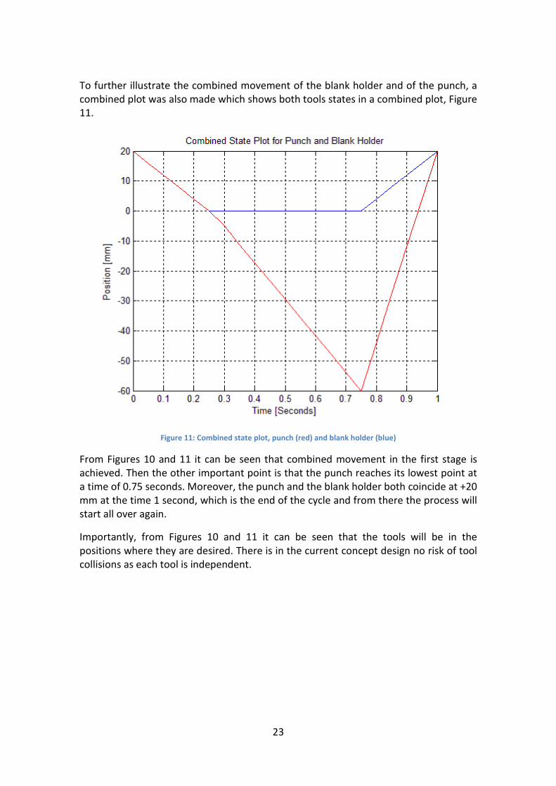
To further illustrate the combined movement of the blank holder and of the punch, a combined plot was also made which shows both tools states in a combined plot, Figure 11.
Figure 11: Combined state plot, punch (red) and blank holder (blue)
From Figures 10 and 11 it can be seen that combined movement in the first stage is achieved. Then the other important point is that the punch reaches its lowest point at a time of 0.75 seconds. Moreover, the punch and the blank holder both coincide at +20 mm at the time 1 second, which is the end of the cycle and from there the process will start all over again.
Importantly, from Figures 10 and 11 it can be seen that the tools will be in the positions where they are desired. There is in the current concept design no risk of tool collisions as each tool is independent.

24
Velocity plots
Using the built in MATLAB function diff(X), the velocity profiles were obtained. The split velocity plot is shown in Figure 12.
Figure 12: Velocity plots for the blank holder and the punch

25
To further compare these in relations, the velocity profiles were combined into a single plot in Figure 13.
Figure 13: Combined plots for velocity, punch (red) and blank holder (blue)

26
Acceleration plots
Furthermore, the velocity was differentiated with respect to time one more time to obtain the acceleration required from the drives for the tools. There is then a very clear indication of how much force that the drives need to deliver for acceleration. The split acceleration plot is shown in Figure 14.
Figure 14, Split acceleration plots for the blank holder and punch

27
To further show these in relation to each other the acceleration profiles were combined into a single plot in Figure 15.
Figure 15, Combined plots for acceleration, punch (red), blank holder (blue)
Summary Based on the state, velocity and acceleration plots a more detailed and limited requirement and design space for the drives was created. It is clear that in order to minimise the requirements of the drives the maximum extension of the punch is 60 mm (below the zero level). This results in a required drive speed below 350 mm/s.

28
Conceptual design work The first step during the conceptual design work was to engage in a brainstorming process in order to formulate a set of concepts no matter hope odd or out of place they may seem at first the idea was to document anything which can be useful. Relating to the words of Prof. Mårten Olsson at KTH “The only rule of brain storming concept ideas is no criticism”
According to the specification that has been worked out in the previous chapter, a few important factors need to be considered:
1. The actuators have to be compact enough to fit into a system of size similar to the state of the art.
2. The system has to be able to achieve an accurate force control and be constructed in such a way as to allow for implementation, post production modification and addition of different sensors.
3. The speed of the actuators has to be considered. 4. The total cycle time of the actuation, drawing and release have to be as short
as possible in order to achieve a goal of 800 cups/min. 5. The actuators have to be positioned as not to obstruct the infeed of the
blanks. 6. Cycle have to be able to match the rotation of the global system/machine. 7. The system has to be able to withstand the centripetal forces of the rotation of
the global machine.
Concept numbering The concept numbering is as follows:
Concept X Num1 – Num2
Where X relates to the frame type
A – State of the art 2 or 3 leg frame as used today
B – 2 beam frame with large linear crews,
Num1 to the type of actuator system
1 – Linear actuators
2 – Ball screw type actuator, and
Num2 to the idea number

29
Concept A1 - 1
Figure 16: Concept A1 – 1

30
Concept A1 – 1 is a direct adaptation of the test rig as it is designed today. The hydraulic actuators are replaced with three electromechanical linear actuators; two actuators for the blank holder and one for the punch. The blank holder actuators are mounted below the drawing cavity and pull to actuate. This concept idea uses similar space as the state of the art and would have the actuators mounted in the space previously occupied by the counter holder hydraulics.
Advantages
Disadvantages
Simple- Since it uses the same frame as available today.
Takes up more space than if all actuators are mounted “in line”
Uses electro mechanical linear actuators which are fast, strong and reliable.
Actuators may obstruct infeed
The system has a low centre of gravity and only has the mass of the punch actuator mounted below the cavity and blank holder.
Uses off-the-shelf technology.

31
Concept A1 -2
Figure 17: Concept A1 – 2

32
Concept A1 – 2 is very similar to A1 – 1, however, it mounts all actuators above the blank holder and allows for an all over more compact design.
Advantages
Disadvantages:
Simple- Since it uses the same frame available today.
Higher centre of mass
Compact – all actuators are mounted above and hence use less space in the vertical direction.
May be considerably more compact and hence harder to access actuators for maintenance.
Allows for an overall smaller system.
It frees up the space below for unrestricted use of exit chute and/or other system components.
Uses off-the-shelf technology.
33
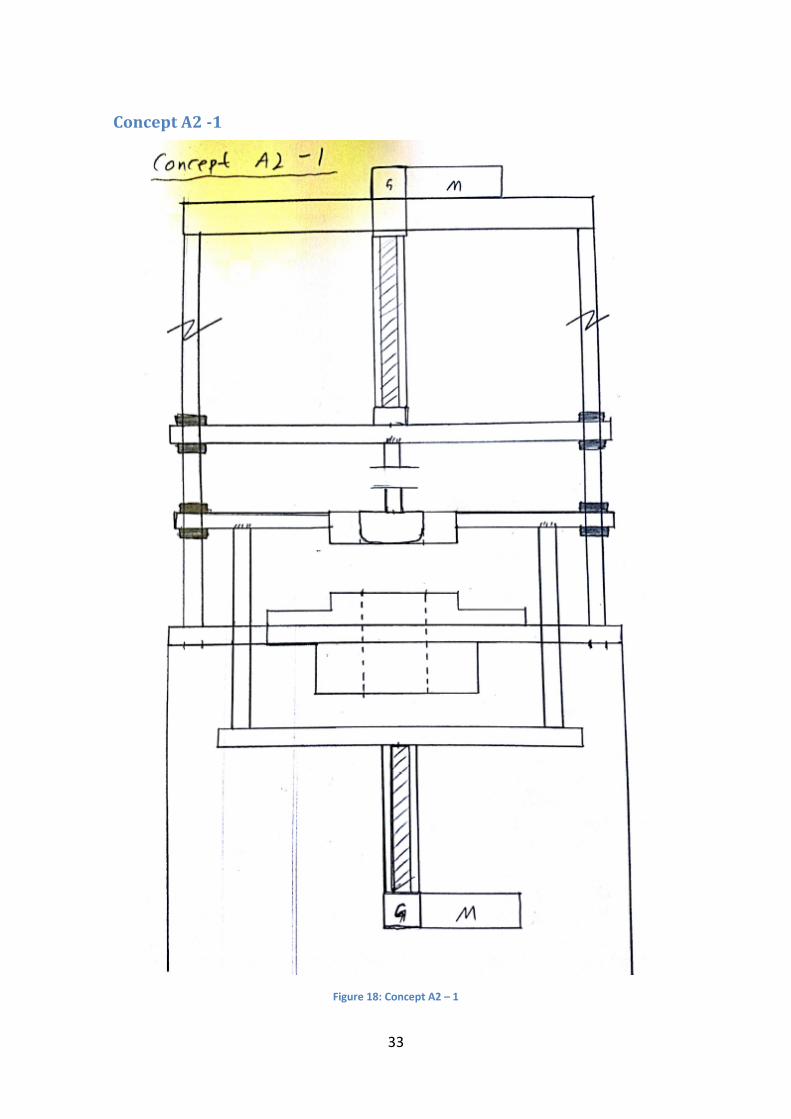
Concept A2 -1
Figure 18: Concept A2 – 1

34
Concept A2 – 1 is similar in design to the second test rig available at TU-Dresden (Only briefly mentioned earlier). This system also uses only a single actuator for the blank holder.
Advantages
Disadvantages
System uses only two actuators and hence reduces maintenance.
It uses considerably more space than other concepts.
System uses only a single actuator for the blank holder mechanism which means that there are no risks of eccentricities.
Uses a technology that is not fulfilling the accuracy requirements that are expected today.
Uses off-the-shelf technology.
Concept A2 – 2 / Concept A1 -3 This is a combination of the previously mentioned systems. The frame and layout are those of concept A2 – 1. However, it will use electromechanical linear actuator instead of the ball screw linear actuators.

35
Concept B1 – 1 and 2
Figure 19: Concept B1 - 1 and 2

36
Concept B1 – 1 and 2 is an adaptation of the system components found on a universal material testing machine. This concept has a double column circulating ball screw type of drive. This enables the blank holder to be simply constructed using the screw column to actuate and travel. This also allows the servo motor to be placed below the cavity assembly. The screw columns are driven by a single motor and gear system.
However, this concept would still need a linear actuator or a further ball screw drive for the punch function.
Advantages
Disadvantages
The blank holder mechanism servo drive is placed low in the system.
Requires two separate systems for punch and blank holder actuators.
Does not depend on synchronising two drives.
Still has the problem of mounting two separate actuator system one above and one below the draw cavity.
More complex construction using less or no standardised products.
Little or no off-the-shelf products.

37
Choice from the conceptual work The conceptual work and the drawings were analysed and two concepts were short listed, namely Concept A1-1 and Concept A1-2. These concepts each have their advantage and disadvantages.
Concept A1-2 was the preferred concept for the following reasons:
1 It is more compact 2 It uses all electro-mechanical cylinders mounted close (less cable work) 3 It allows for a simpler blank holder construction 4 It could allow for elimination of guides for the punch and blank holder
Based on the above points it can also be deducted that two different approaches should be tried:
1 A two drive configuration for the blank holder, as shown in the concept sketches.
2 A single blank holder drive configuration where one of the drives is eliminated.
The chosen concept is to be evolved into a design where it forms part of a larger unit. It is one of several symmetric/identical units being parts of a rotary machine. It is to be as small as possible. First the drives were chosen to given an idea of the space requirements then the work began to develop a feasible design.

38
Choice of drives Based on the concept ideas the best and most simple system to implement would be the use of electromechanical linear actuators. This would allow for almost instantaneous refit to the present test rig for the use as a basis to test the system. Furthermore, it allows for a standard off-the-shelf product range to be utilized. It is proposed to make use of SKF modular electromechanical linear actuators. Also recommended are the Exlar® Corp. Electromechanical actuators.
The use of off-the-shelf products like SKF Electromechanical actuators allows for a shorter development time. It would also allow for the possible construction of a test rig to make experiments of the closed loop force control system.
The basic technology for most industrial electromechanical actuators is the same. The most common system is using planetary screws to move the threaded actuator rod. This system allows for long life as well as superior positioning and system control. They are also designed for high or very high force applications. The systems have two types of motors. Systems that use an inline motor positioned behind the actuator or a motor positioned parallel to the actuator. There are also systems like the Exlar actuators where the motor is positioned inside the actuator around the planetary gears.
Suggested fields of application of the SKF Electromechanical cylinders are among others servo pressing and thermoforming [19,21]. This method, especially for paper is very similar to the deep drawing process. However, those applications require significantly larger forces than the deep drawing process. According to the product specifications the SKF Electromechanical cylinders are far superior to the use of hydraulics. Efficiency is stated at above 80 %, maintenance is low, lifetime is very long, speed and acceleration is very high, shock resistance is very high, installation is easy and there are no external or environmental concerns.
Cycle time The cycle time have to be coordinated with the rotations of the global system as to ensure a smooth and fast operation. The cycle time was previously established, and the speed and acceleration requirements found from the state, velocity and acceleration plots. As mentioned a ¾ cycle will be used.
Distances The gap of the blank holder, punch and cavity into which the blank will be fed is estimated to 50 mm to allow for infeed using tools. The draw cavity was estimated to 100 mm, then a further 100 mm for maximum cups would be needed. This gives a working stroke of 50 mm and a total cycle of 100 mm for the blank holder cylinders. For the punch the stroke will be 250 mm and for a total cycle 500 mm.

39
Speed requirements Based on the above assumptions, using a ¾ cycle, the estimated speeds are given in Table 4.
Table 4: Speed requirements
Tool Distance one way
Time actuation
Mean speed actuation
Time return
Mean speed return
Blank holder
50mm 0.25 sec 200 mm/s 0.25 s 200 mm/s
Punch 250mm 0.5 sec 500 mm/s 0.25 1000 mm/s
Example using SKF Electromechanical cylinders, SRSA The following SKF method for the selection of cylinder [21] as illustrated in Figure 20.
Figure 20: SKF selection model [21]

40
SRSA and SVSA product range Based on the schematics in Figure 21 it can be clearly seen that the SKF modular range should be sufficient for the present requirements (max speed 1000mm/s, load 12KN). However, it should also be noted that depending on the design of the blank holder it could also be suitable to instead use the CEMC, Compact Electro Mechanical Cylinders for the blank holder mechanism.
Figure 21: SKF SRSA and SVSA product range [21]

41
Cycle Time and Tool Motion The motion of the tools has to be synchronised with the motion of the rotary machine as well as with each other. There is a main point where the tools have to be in a certain position and this is the so called zero position of the rotor. This is the start of the cycle and the point of infeed of the paper blanks.
It was decided that the cycle should follow the ¾ principle described above. This allows for the most utilisation of the tools. The tools or work pieces will be utilised for ¾ of the time and the return is compressed into ¼ of the time.
The entire cycle will be 1 second for the first stage of the work.
The number of work pieces will be a multiple of four. As the rotor will be split into four sections and three will be in use it is suitable to have a multiple of four. To a start the initial basis design will aim towards a 12 or 16 work pieces machine.
For the first example a 12 work piece machine would require each section to occupy no more than 30 Degrees of total space. The rotor will be designed accordingly. For the second example with a 16 work piece machine each section can occupy 22.5 degrees.
Biased preferences Based on the availability of the SKF off-the-shelf products the SKF CEMC range is to be preferred as mentioned above. Furthermore, the desire is to find a cylinder that is as small as possible or has a diameter of the extending rod as small as possible. Ideally it should be no larger than 30 mm. Based on this a bias was introduced into the drive selection scheme which otherwise could have used almost any types of electromechanical cylinders.
42
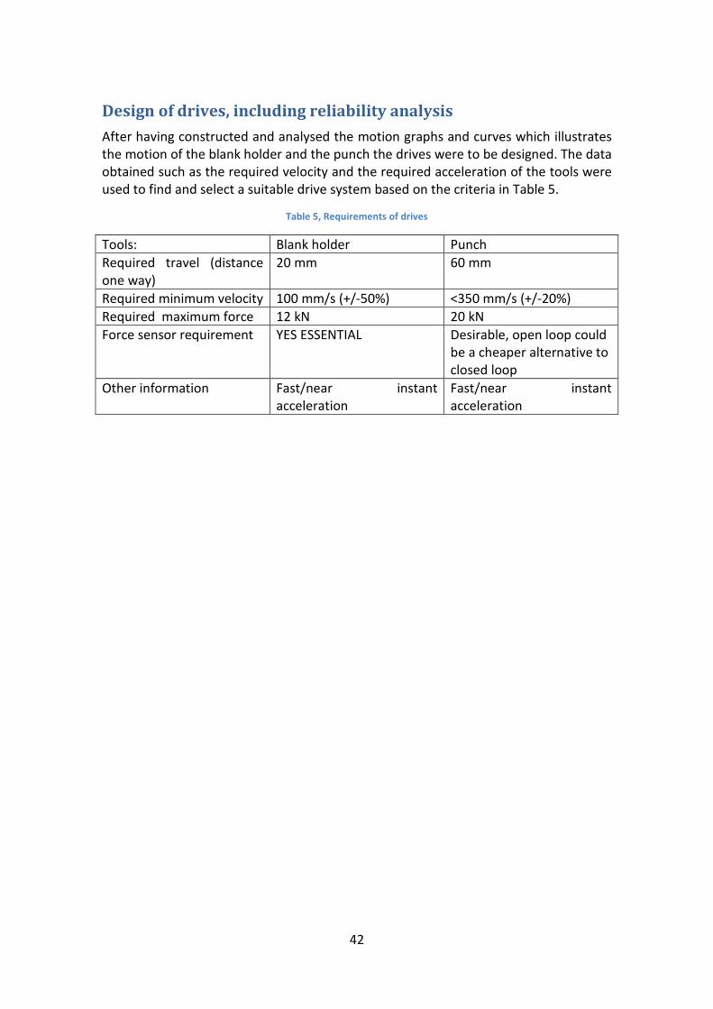
Design of drives, including reliability analysis After having constructed and analysed the motion graphs and curves which illustrates the motion of the blank holder and the punch the drives were to be designed. The data obtained such as the required velocity and the required acceleration of the tools were used to find and select a suitable drive system based on the criteria in Table 5.
Table 5, Requirements of drives
Tools: Blank holder Punch Required travel (distance one way)
20 mm 60 mm
Required minimum velocity 100 mm/s (+/-50%) <350 mm/s (+/-20%) Required maximum force 12 kN 20 kN Force sensor requirement YES ESSENTIAL Desirable, open loop could
be a cheaper alternative to closed loop
Other information Fast/near instant acceleration
Fast/near instant acceleration

43
Selection of drives for the blank holder The selection of drives for the blank holder will follow a suggested SKF schematic for the selection of cylinders from their catalogue. This is previously shown in Figure 20. For ease it is shown here again but in smaller format in Figure 22.
Figure 22: SKF Selection schematic
Based on Figure 20/22, the following holds. Load is Below 250 kN and speed above 125 mm/s. Stroke is below 170 mm and load is below 30 kN. Hence, the CEMC – Compact Electro Mechanical Cylinders should be selected.
In order to select a drive the nominal force, nomF has to be calculated from the thermal load on the motor, thermalF . This is done according to the SKF formula [21]:
0.7thermal
nomFF = (0.1)
where thermalF is found from
2 2 2 1/2
1 1 2 2 3 31/2
1 2 3
(T T T )(T )thermal
F F FFT T
+ +=
+ + (0.2)
Note that T1, T2 etc. refer to the times of each load step and F1 etc. the load.

44
Equation (1.1) with (1.2) and inserted values gives the required nominal force 19.6nomF = kN. Based on the nominal force and the required speed a drive was
selected from the list [21]. The drive that fits the requirements closest is the CEMC3004-XXX-2-D84H.
This drive has an allowed nominal force of 27.4 kN and a maximum speed of 266 mm/𝑠𝑠2. Hence the drive is over dimensioned but the next option in the range is only at 18.3 kN and hence does not guarantee the motor for the rated load. These are, however, the same drive and motor, but only with different screw leads and hence load rating and speed.
Despite the fact that the selection of a CEMC is to be preferred, the choice still had to be confirmed to make sure that an appropriate cylinder is selected. There are several reasons for the preference of the CEMC unit. These include the integration of a force sensor with a worst case stated accuracy of +/- 3 %. The integrated force sensor is essential for the application since the whole process depends on the ability to control the force in the blank holder. If instead the force was controlled via a so called open loop system a best case could be +/- 10 % accuracy which is simply not good enough.
Furthermore, the CEMC range offers built in cooling at no increase in cylinder size. The built in cooling could become necessary if it shows that the constant engine rotation heats the cylinder above desirable levels. Yet more parts of the machine are heated and this will heat-up even the non-heated components.
It should noted that the CEMC and UCEMC (Ultra Compact) range are similar in all aspects apart from appearance. Integrated load, sensor etc. are the same for both.
45
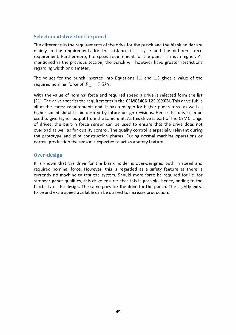
Selection of drive for the punch The difference in the requirements of the drive for the punch and the blank holder are mainly in the requirements for the distance in a cycle and the different force requirement. Furthermore, the speed requirement for the punch is much higher. As mentioned in the previous section, the punch will however have greater restrictions regarding width or diameter.
The values for the punch inserted into Equations 1.1 and 1.2 gives a value of the required nominal force of 7.5nomF = kN.
With the value of nominal force and required speed a drive is selected form the list [21]. The drive that fits the requirements is the CEMC2406-125-X-X63I. This drive fulfils all of the stated requirements and, it has a margin for higher punch force as well as higher speed should it be desired by future design revisions. Hence this drive can be used to give higher output from the same unit. As this drive is part of the CEMC range of drives, the built-in force sensor can be used to ensure that the drive does not overload as well as for quality control. The quality control is especially relevant during the prototype and pilot construction phases. During normal machine operations or normal production the sensor is expected to act as a safety feature.
Over-design It is known that the drive for the blank holder is over-designed both in speed and required nominal force. However, this is regarded as a safety feature as there is currently no machine to test the system. Should more force be required for i.e. for stronger paper qualities, this drive ensures that this is possible, hence, adding to the flexibility of the design. The same goes for the drive for the punch. The slightly extra force and extra speed available can be utilised to increase production.

46
Machine design For the machine design there are two main concept ideas to consider. Firstly, the design should be stiff enough and the cavity should be accessible for the blank infeed mechanism.
This leads to two concepts, one where an overhang configuration is designed and a second similar to the current test rig configuration.
Design of the components The complete unit had to be designed and as mentioned above only the most important parts in the construction have been analysed and optimised. Other parts have simply been designed to the purpose to produce a working prototype.
Shape optimisation and static structural load The simulation of the components to be optimised included a static structural setup to simulate the load state and enable estimation, of stress and deformation. Then a shape optimisation simulation was run to optimise the shape.
In Figure 23, the different part that are to be optimised are shown in their context in the machine. The illustration is the design before the optimisation.
Figure 23: The components to be optimised illustrated in context before optimisation

47
Shape optimisation of the side brackets
The design of the side bracket was made using ANSYS ® shape optimisation as a tool to verify the design. The basic design was first created to fulfil the basic functions regarding stiffness and height. The design was then optimised to keep deformation and stresses low while decreasing the weight. Various cut-outs were investigated and then the shape optimisation was used to verify those.
The setup had to replicate the real load as far as it was known. The load is simply half of the load by the two drives exerted lifting the top plate. The component is subjected to body forces (earth gravity) and it is fixed to the base plate and the base plate can be assumed rigid. Furthermore, as the next unit will attach to the side only by contact the bracket cannot bend in that direction. This is simulated by a frictionless support. The setup is shown in Figure 24.
Figure 24, Static structural set up of side brackets
The shape optimisation software was then run to allow the shape to be optimised. The loops were recorded and compared in a table.
However, it has to be noted that including the frictionless support in the shape optimisation does not allow the relevant side to be optimised. The software does not consider a frictionless side as it is assumed to be load bearing. Hence after much deliberation it had to be removed. Its effects on the accuracy of the model are known, but have to be used otherwise the shape optimisation will not work. This is also the shape optimisation is only a BETA software hence there are limitations.

48
The shape optimisation was mostly used to aid in the design work and to verify the considered removals of material. Table 6 below shows the steps in the optimisation process.
Table 6: Optimisation loop steps for the design of the side brackets.
Brackets Thickness Max stress Deformation Weight Shape Opt
No cut-out 15 mm 19.78 MPa 38.9 10−× mm 4.843 kg Cut material, middle front and rear
Front, rear and middle cut-out
15 mm 38.40 MPa 32.2 10−× mm 2.676 Kg Remove middle
Even though the shape optimisation in ANSYS suggests the removal of more material, this will not be done as it will affect the other components in the construction. For instance the base and top of the component have to be a larger area than suggested as there has to be sufficient space for the mounting screws. Furthermore, the placement of the screws is limited by the above placed components such as the blank holder drive brackets. Hence, the optimisation process has allowed the removal of 2.2 kg of material and still keeping the stress level in the component low by optimising the load bearing design.
The finished shape is presented in Figure 25.
Figure 25: A final design of an optimised side brackets

49
Shape optimisation of the blank holder drive brackets
By analysing the expected force flow in the component the simplest design would be a straight bar with large cross sectional area as the component is mainly loaded in repeated tension. However, the drive can be expected to slightly move due to the deformation of the blank holder. Furthermore, the design had to allow for vibrations and hence had to take on a more stable design, such as a large base area. Also a large base area is preferred for mounting the component to the plate. The most logical is to use a triangular design. However, to optimise the structure the design had to keep its side legs irrespective of the shape optimisation suggestions. The basic weight reduction was to cut away material to triangular shapes while keeping a middle section and legs. This was verified by the suggestions of the shape optimisation software. The Simulation setup is shown in Figure 26.
Figure 26: Blankholder bracket
Table 7: Blankholder bracket optimisation loop steps
Drive holder Thickness Max stress
Deformation Weight Shape opt suggestions
No cut out
18 mm 40.79 MPa
39.8 10−× mm 2.584 kg Cut sides?
Shape 2 18 mm 40.40 MPa
31.14 10−× mm 1.962 kg Make cut out larger
Shape 3 18 mm 40.39 MPa
31.18 10−× mm 1.820 kg Remove more on base

50
The result of the shape optimisation analysis is seen in Table 6 above the shape has been optimised. The slight increase in deformation is allowed since it is still a very small deformation.
The finished optimised bracket for the drive of the blankholder is shown in Figure 27.
Figure 27: Optimised blankholder drive bracket

51
Blankholder
The blankholder need to be designed with considerations of several important factors.
1 The deformation has to be as small as possible 2 Keeping the deformation small while also keeping the weight low to
minimise inertia load 3 Keeping the design stiff enough to produce a good contact pressure
distribution. 4 Make it possible to have a single drive moving the blankholder 5 Incorporate a guidance solution
The simplest solution to solve the issue of the contact problem is to have a demountable upper cavity ring which is largely solid steel, and hence would be very stiff allowing the blankholder to absorb the deformation. The basis is a two guidance solution using linear sliding bearings where the punch moves inside the guiding solution either with or without guidance. The attachment of the drive to the blankholder is done via two blocks attached to the base with large M10 screws. A guiding tube is then fitted outside the inner tube to provide a smooth sliding/guiding surface for the sliding bearings. The simulation of the basic plate is shown in Figure 28.
Figure 28: Blankholder base plate, showing front inner guiding tube and mounting for rear inner guiding and drive
attachment
The shape optimisation steps suggested are shown in a table, Table 8.

52
Table 8: Blankholder optimisation loop steps
Blank holder Thickness Max stress Deformation Weight Shape opt No cut out 20 mm 17,643 MPa 0,00378 mm 8,388 kg Cut away
sides Sides rounded
20 mm 19,554 MPa 0,00377 7,043 kg Cut away by front
The shape optimisation analysis now suggests that material be cut away from places where it is needed to attach the screws from the upper cavity. Hence, this procedure suggests that there is no more material that can be cut-out.
It has to be noted that as the cylindrical support is used around the sliding bearings, these parts will not be considered for the optimisation. Furthermore the simulation setup was also tried using frictionless supports instead of cylindrical and the results were identical. The Finished unit can be seen in Figure 29.
Figure 29: The finished blankholder plate
The top plate
The top plate was simply designed to fulfil its role with as low deformation and weight as possible. Furthermore, the need to include cut outs and holes for mounting the drives and places for cables etc. was considered. The main objective was as previously stated, to minimise the deformation to ensure that the alignment of the drives and mainly the punch would not deviate and cause damage or decrease quality of the finished product.

53
The resulting component has low deformation. Stress concentrations do occur. However, parts of these results are due to the simulation setup. In order to simply simulate the screw attachments the screw holes use fixed supports. Hence, the reality of larger contact areas was neglected.
However, the deformation is 87 µm at the front of the plate, the maximum stress is 88 MPa, but it occurs mainly around the screw holes. The nominal stress state in the plate is only around 40 MPa.
The bottom plate
The bottom plate had to be as stiff as possible, yet be able to accommodate the drawing cavity in the front of the plate. The bottom plate has been considered as stiff throughout the entire simulation process. As expected the front of the plate would not be stiff and it will deform as the cup is drawn. However, the rest of the plate attached to the larger machine will be fixed and can be approximated as stiff. The fixed part, which likely would be fixed to the rotor of the global machine, is the part where the side brackets are attached.
The deformation of the bottom plate is still within tolerable limits. The maximum deformation is 78 µm, while the maximum stress is 52 MPa. Stress concentrations occur at the side of the plate where the front portion bends, close to a rounded corner (see Appendix B).
The cavity
The cavity has been designed simply to fulfil its function. There has been no detailed optimisation work as this was not part of the project. The cavity had to be able to accommodate a heating element. In the current test rig the heating element is a heating ring. The new design proposes using four cartridge heaters requiring less space and allowing for common heaters in the cavity and the punch.
Most importantly the cavity has to be insulated from the bottom plate. This is achieved by a PEEK® ring. The ring allows the cavity assembly to be attached to the bottom plate. The cavity is then in turn fastened to the PEEK® ring. Hence, the heated cavity is fully insulated from the bottom plate.

54
The punch
The punch has to be designed to be stiff and at the same time being able to be heated. As mentioned above, the punch unit and the cavity unit has the same type of cartridge heaters. The punch also has to be insulated from the attaching screw. As the Attaching screw fits right through the entire assembly there has to be two insulation rings that completely insulate the heated unit from the screw. There is to be no direct contact. An insulation ring insulates the top part from the heated unit. An insulation ring also fits between the screw and the screw head. An exploded view is shown in Figure 30 with a corresponding parts table, Table 9. Further views of the punch assembly are given in Appendix B.
Table 9: Labelling of the punch unit
A-M20 Fastening screw B-PEEK lower insulation C-80 mm punch body D-PEEK upper insulation E-Centering/anti rotation
top part F-Cartridge heaters
Figure 30: Exploded, annotated view of the punch assembly
PEEK® Material
The PEEK material is a polymer that exhibits very good mechanical properties while also acting as an insulation material. PEEK is currently being used as insulation in the test rig at TU Dresden. The material is very stiff and has high tensile and compression yield limits which allows it to be used in the construction where parts are under compression. The cavity insulation ring is subjected to a force of 17 kN and the Punch top-insulation ring to a force of 5 kN.

55
Screw, nuts, bolts and locking rings The unit has been designed to be assembled and held together by the use of standard M5 and M10 screws and a single M20 screw. The punch drive is fastened using eight M5 screws. The Brackets holding the blankholder drive is fastened with M10 screws. The brackets holding the top and bottom plates are also fastened using M10 screws. The cavities, both the drawing cavity and upper cavity in the blankholder, are fastened by M5 screws. The Blankholder also uses M10 screws to secure the drive to the blankholder unit.
Most screws have been placed so that they are not subjected to tension but rather to mild compression. The tension in the screws will be due to the fastening and pretension and in the retraction of the tools, mainly due to inertia forces.
The stress behaviour of the most critically loaded screws bolts and nuts have to be investigated. This is done by simple calculations taken from [22] and [23]. Details of these calculations can be found in Appendix A.
According to [23], the pre-tension in the screws are calculated to be about 73% of the yield strength. For a list of the recommended pre-tension in the unit see appendix A.
As the machine is subjected to motor motion and rapid cycles, vibrations are expected to occur. To stop nuts and screws from undoing themselves, locking rings are used. The locking rings work on the principle of a two part with an angled tooth design where the angle is greater than the taper angle of the screw. The locking rings also offer the advantage of acting as a washer spreading the contact area from the screw head and nut on the components being fastened. In this design NORD LOCK locking rings/washers have been used. They are, however, replaceable with any type of locking ring.
56
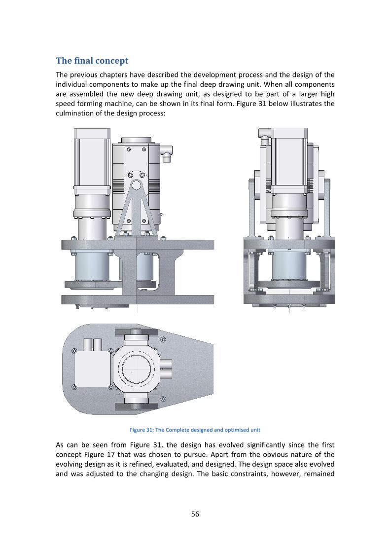
The final concept The previous chapters have described the development process and the design of the individual components to make up the final deep drawing unit. When all components are assembled the new deep drawing unit, as designed to be part of a larger high speed forming machine, can be shown in its final form. Figure 31 below illustrates the culmination of the design process:
Figure 31: The Complete designed and optimised unit
As can be seen from Figure 31, the design has evolved significantly since the first concept Figure 17 that was chosen to pursue. Apart from the obvious nature of the evolving design as it is refined, evaluated, and designed. The design space also evolved and was adjusted to the changing design. The basic constraints, however, remained
57
the same. As the design evolved the design space could be narrowed and was allowed to shrink.
Even though a design space should take into consideration the constraints which should not change if a project is well defined, the nature of the development work meant that not all constraints were fully defined at the start of the project.
However, as the work progressed and it was shown that certain aspects, which had merely been a question of feasibility was possible it meant that the constraints could be narrowed.
In reality, the constraints were changed and narrowed when it became obvious that the design would satisfy all requirements and constraints. In other words the requirements were increased to a point where the design, to the best knowledge, was optimised and the requirements could no longer be updated.
In order to show the components previously described, Figure 32 and Table 10 shows an annotated exploded view and the corresponding table of parts.

58
Figure 32: Annotated view of redesigned new unit
Table 10: Figure 32 parts description
A-Base plate B-Brackets (Supports)
C- Cavity PEEK insulation
D-Heated Cavity Body
E-Heated Punch Body
F-Upper Cavity/Blankholder contact area
G-Blankholder plate
H-Sliding bearing
I-Fastening screws M10
J-Blankholder bearing guiding’s
K-top plate L-rear end towards rotary machine body
M-Drive holder brackets (Blankholder)
N-Punch Cylinder CEMC2406
O-Blankholder cylinder CEMC3004
59
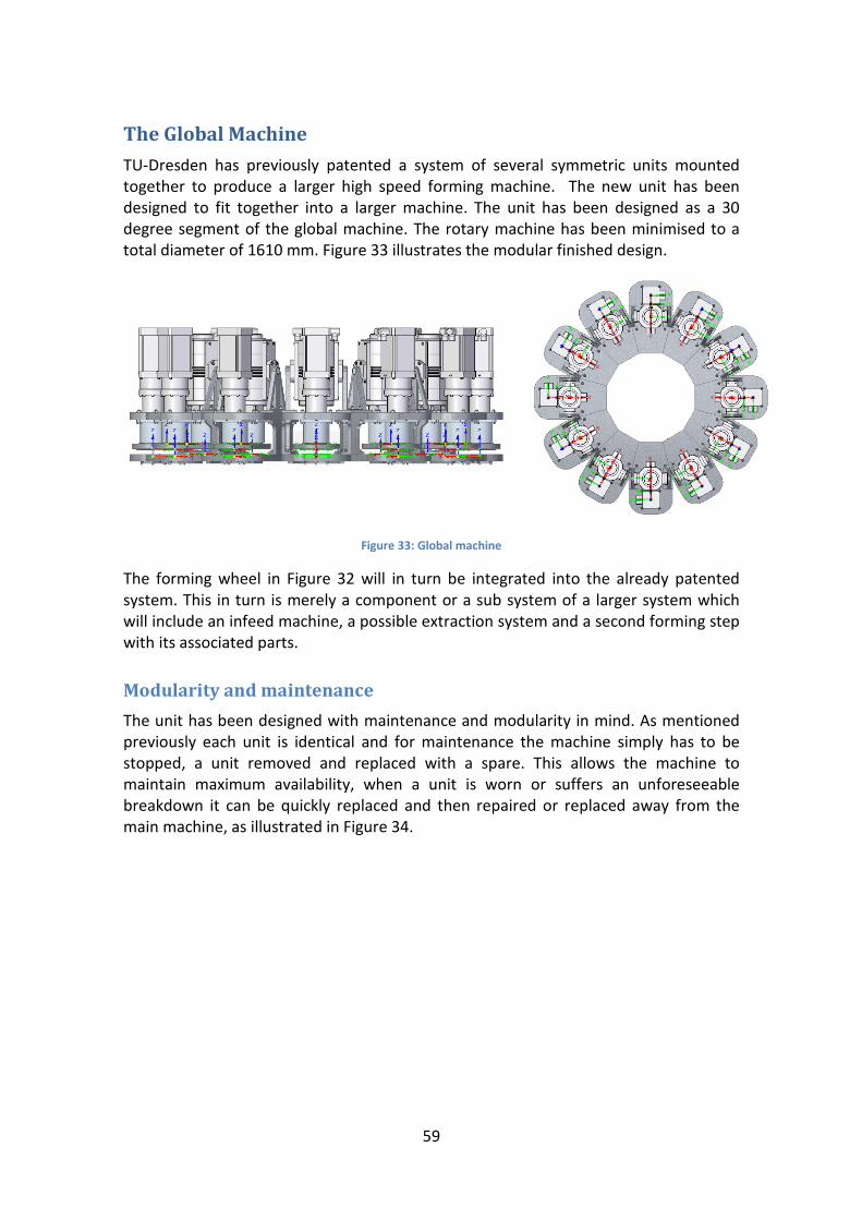
The Global Machine TU-Dresden has previously patented a system of several symmetric units mounted together to produce a larger high speed forming machine. The new unit has been designed to fit together into a larger machine. The unit has been designed as a 30 degree segment of the global machine. The rotary machine has been minimised to a total diameter of 1610 mm. Figure 33 illustrates the modular finished design.
Figure 33: Global machine
The forming wheel in Figure 32 will in turn be integrated into the already patented system. This in turn is merely a component or a sub system of a larger system which will include an infeed machine, a possible extraction system and a second forming step with its associated parts.
Modularity and maintenance The unit has been designed with maintenance and modularity in mind. As mentioned previously each unit is identical and for maintenance the machine simply has to be stopped, a unit removed and replaced with a spare. This allows the machine to maintain maximum availability, when a unit is worn or suffers an unforeseeable breakdown it can be quickly replaced and then repaired or replaced away from the main machine, as illustrated in Figure 34.

60
Figure 34, Visualisation of the modularity
Furthermore, it should also to be noted that the unit currently contains a design for an 80 mm cup base. There is, however, the possibility to simply replace the cavity, the punch and the blank holder contact part (Upper cavity) to form cups with a smaller base diameter.

61
Conclusion This report has described the development process and the design of the individual components to make up the final deep drawing unit. Hence, from the chapters of this report several conclusions can be drawn. These satisfy the questions and statements in the task description.
1 It is possible to construct a more compact unit. 2 It is possible to switch from hydraulic to electric cylinders. 3 It is possible to achieve a high output, above 700 cups per minute. 4 The work and experiments have shown that it is possible to form cups
at higher speeds. 5 The unit is part of a 12 equal unit high speed rotary machine. 6 The high speed rotary machine has achieved an overall diameter of 1.63
metres. 7 A new, more compact and simplified blank holder assembly has been
designed. 8 A new, simpler punch assembly with integrated guidance has also been
suggested and designed.
Throughout the entire design process many different approaches to the design of the new forming unit has been tried.
Vibration considerations There are electric motors and components moving with very high cyclic rate in the system. Therefore, vibrations are expected in the system. As this is only a design phase the vibrations are not known. However, the design has taken into consideration the fact that vibrations will occur. This is shown in the design by the following observations.
1 Design against fretting corrosion as far as possible. 2 All screws have a locking ring to stop unscrewing by vibrations. 3 Screws will be pre-tensioned. 4 Punch guidance has tolerance to accept vibrations. 5 Sliding bearing in softer, less transmittable material than steel to reduce
vibration throughout the system.
In order to avoid fretting corrosion there are no small area contacts like pin heads on larger surfaces (i.e. ball bearings). All contacts have been designed to be flat and there will be no sliding between metals. All moving components will either have sufficient clearance or a sliding bearing.

62
Tribology considerations As the tools are involved in rapid motion where there are also vibrations and heat the design needs to take this into account. For instance the sliding bearing is able to cope with the expected vibrations in the system. The tolerance of the punch and its guiding is according to standard. As components that have a motion relative to each other they are separated by a bearing or an appropriate form of lubrication. The main important areas are described in Table 11.
Table 11: Tribological considerations
Blankholder guidance: PCM sliding bearing, and polished surfaces to prolong the bearing life Punch guidance, if extra bearing included: Sliding bearing and polished surface Blankholder drive cylinder attachment to blankholder: Rod via trunnion, lubricated by food grade grease which is able to take the pressure and movement. The drives/cylinders will use manufacturers recommended lubrication however they have to be of food grade. Finally, this project has not taken into account the frictional effects of the paper sliding over the cavity in feed radius, sliding between the blankholder and the cavity as it is being drawn and the sliding through the cavity. These effects are not considered essential to this work. Currently, research is being done in this field at TU Dresden.
Recommendations for further work The entire design process has been as accurately as possible with known data. However, there are a few points that should be investigated in more detail and therefore more work needs to be carried out. The author recommends the following steps to extend on this work:
1 An infeed mechanism 2 An extraction mechanism 3 Infeed/extraction if unit is to be used as second stage drawing process 4 Building of a test rig to try the new concept 5 Investigations into the real life accuracy of the force control setup and
the ability of the electric cylinders to more exactly follow the linear blankholder force profile.
6 More research on the vibrations of the global system

63
Acknowledgements The author wishes to thank:
Dr. Ing. Marek Hauptmann – Host and supervisor at TU Dresden, Also Co-Inventor
Prof. Sören Östlund – Examiner at KTH
Alexander Lenske, Malte Wallmeier and Albrect Löwe for their help, tips and extra insight in the test-rig, current issues and the current research being done at TU Dresden.
64
References [1] Hauptmann, M. and Majschak, J.P., “New quality level of packaging
components from paper board through technology improvement in 3D forming”, Packag. Technol. Sci. 24: 419–432, 2011.
[2] Hauptmann, M., Erhard, K., Zelm, R., Majschak, J.P., “The role of material composition, fibre properties and deformation mechanisms in the deep drawing of paperboard”, Hauptmann et al, Cellulose, 2015 Vol. 22 Issue 5.
[3] Niskanen, K. (Ed.), Mechanics of Paper Products, de Gruyter, Print ISBN 9783110254617, E-book ISBN 9783110254631, 2012.
[4] Vishtal, A. and Retulainen, E., “Deep-Drawing of paper and paperboard: The role of material properties”, BioResources, Vol. 7(3): 4424, 2012.
[5] BillerudKorsnäs FibreForm® http://www.billerudkorsnas.com/Our-Offer-Old/Materials/Billerud-FibreForm/
[6] Qin, S., Yang, L., Yang, B., “Blank Holder Force Control System Driven by Servo-Motor”, Intelligence force control and automation. 2: 450-455, 2011
[7] Osakada, K. Mori, K., Altan, T., Groche, P., “Mechanical servo press technology for metal forming”, Manufacturing Technology, 60: 651-672, 2011
[8] Groche, P., Scheitza, M., Kraft, M., Schmitt, S.,“Increased total flexibility by 3D servo presses”, Manufacturing Technology, 59: 267-270, 2010
[9] https://www.theegarten-pactec.de/home
[10] https://www.theegarten-pactec.de/packaging-machine/ek4
[11] http://www.sciencechannel.com/tv-shows/how-its-made/
[12] Google.com search query: Rotary moulding machine
[13] http://www.technespa.com/299/ROTAX+showroom+in+Bologna
[14] http://cs.stanford.edu/people/tkr/research/force-control
[15] http://www.controls-group.com/eng/universal-testers-_-steel-re_bars-testing-equipment/electromechanical-universal-tester_.php
[16] http://admet.com/products/universal-testing-machines/
[17] http://admet.com/products/fatigue-testing-machines/
[18] www.exlar.com
[19] www.skf.com
[20]http://www.learneasy.info/MDME/MEMmods/MEM30009A/lifting_systems/ball_
65
screw_actuator.jpg
[21] http://pdf.directindustry.com/pdf/skf-linear-motion/5338-en/320-257685.html
[22] http://www.boltsecuring.com/sv/hallfasthetsklasser-skruv/
[23] Maskinelement Handbok, KTH Maskinkonstruktion, Stockholm, 1st edition, 2008.
[24] Wallmeier, M., Linvill, E., Hauptmann, M., Majschak, J.-P. and Östlund, S., ”Explicit FEM Analysis of the Deep Drawing of Paperboard”, Mechanics of Materials 89: 202-215, 2015.
Patent references [A] Deep-drawn paper tray, a method and an apparatus for making it, and a tray-formed
product package Inventor: RAESAENEN JARI, POEYHOENEN NIILO (+2), Applicant: Stora Enso OY, CPC 1: B29C2791, Main Family: CN104245520 (A), 2012
[B] Deep-drawing arrangement for deep-drawing of e.g. paper for manufacturing package, has blank deformable by relative movement between stamper and die in pressing direction, and micro-corrugation arranged at peripheral surface of stamper Inventor: WIEDUWILT, ULRICH, Applicant: BOSCH GMBH, CPC 1: B31B1/00, 2013
[C] METHOD AND APPARATUS FOR MANUFACTURING PAPER MOLDED ARTICLE , Inventor: NAKAI TAKAYUKI, OWADA MASAMI, Applicant: NAKAI SHIKI KOGYO KK, IPC : B65D1/00, 2010

66
Appendix A - Calculations
Force calculations of the M10 fastenings screws The M10 Fastening screws that hold the top and bottom plate with the brackets are the most loaded components of the entire structure. The maximum loads of an ISO-coarse tapering as standard for M10 screw has the maximum loads according to Table12.
Table 12: Maximum screw load bearing capacity [22]
Class Yield Strength (kN) Ultimate strength (kN) 8.8 37.1 46.4
10.9 54.2 60.3 12.9 63.7 70.8
Hence a single M10 could hold the entire structure. However the use of six fastening screws both at the top plate and ensures that the structure does not deform noticeably or the screws suffer from to large stress levels so that material fatigue will be a problem.
The pre-tensioning of the screws according to [23] is shown in Table 13.
Table 13: Screw pre-tension data
Screw type Force (kN) Moments (Nm) Class 8.8 M5 - 5.7 M10 27.1 52.5 M20 115 434

67
Appendix B – Simulation results
Top plate
Figure 35, Simulation setup
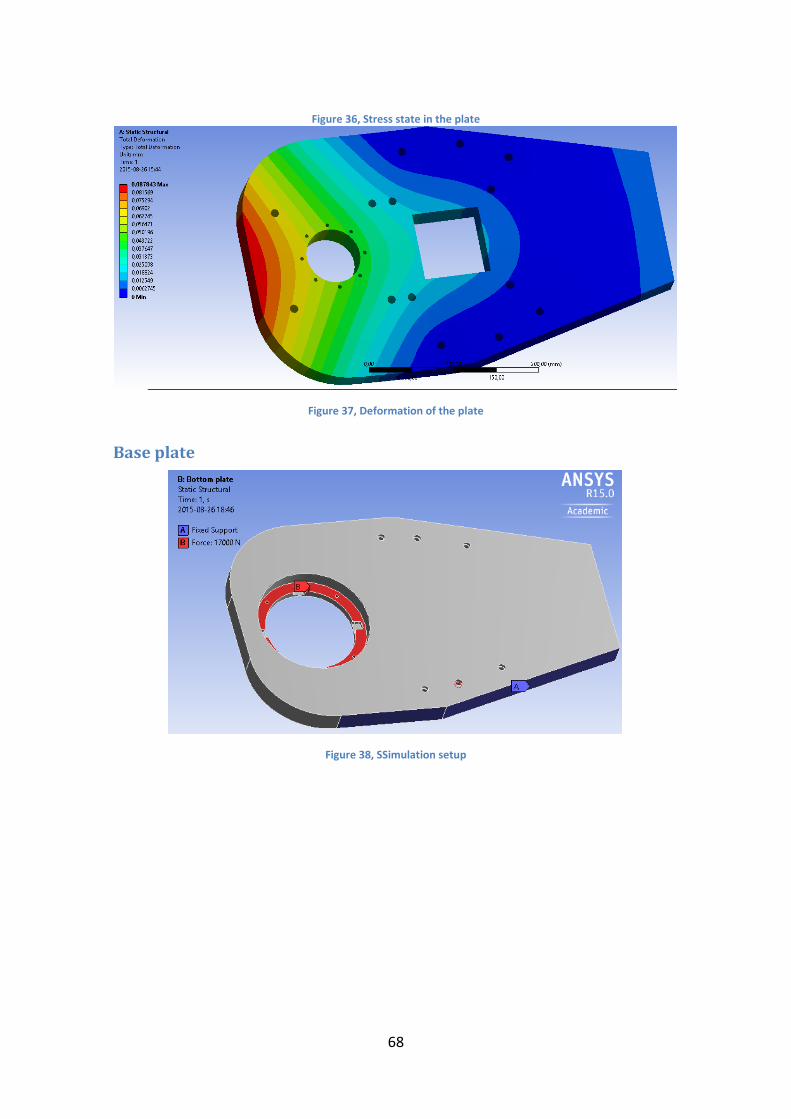
68
Figure 36, Stress state in the plate
Figure 37, Deformation of the plate
Base plate
Figure 38, SSimulation setup

69
Figure 39, Stress state in the plate
Figure 40, Deformation of the plate
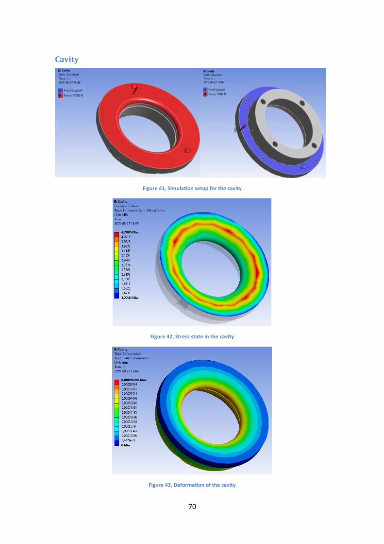
70
Cavity
Figure 41, Simulation setup for the cavity
Figure 42, Stress state in the cavity
Figure 43, Deformation of the cavity

71
Appendix C – CAD Drawings
Global unit drawing

72
Global machine blueprint

73
Complete Unit exploded
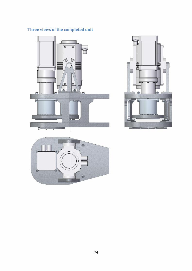
74
Three views of the completed unit

75
New blankholder unit
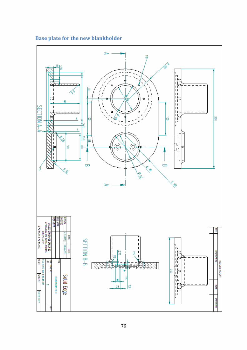
76
Base plate for the new blankholder

77

78

79

80
Appendix C – Patent information


www.kth.se