development for sustainable construction system glass...
TRANSCRIPT

American Journal of Environmental Protection 2016; 5(4): 82-89
http://www.sciencepublishinggroup.com/j/ajep
doi: 10.11648/j.ajep.20160504.12
ISSN: 2328-5680 (Print); ISSN: 2328-5699 (Online)
Development for Sustainable Construction System Glass Fiber Reinforced Gypsum (GFRG) in Egypt Using Nanotechnology
Mohamed Said Meselhy ElSaeed
Department of Architecture, Faculty of Engineering, Fayoum University, Fayoum, Egypt
Email address: [email protected]
To cite this article: Mohamed Said Meselhy ElSaeed. Development for Sustainable Construction System Glass Fiber Reinforced Gypsum (GFRG) in Egypt
Using Nanotechnology. American Journal of Environmental Protection. Vol. 5, No. 4, 2016, pp. 82-89. doi: 10.11648/j.ajep.20160504.12
Received: June 7, 2016; Accepted: June 18, 2016; Published: June 30, 2016
Abstract: One of the mile stones for the success of construction projects is the project management triangle (time, cost and
quality). During the past decade, a lot of construction systems have been developed to this triangle. GFRG system was one of
these systems (for example that was established in Australia), it fulfilled LEED certificate for construction materials. When it is
compared with traditional systems in Egypt, Glass Fiber Reinforced Gypsum (GFRG) system superior to traditional systems in
time, cost in case of repetitive projects and quality. The world awareness for sustainability have increased lately in different
aspects, thermal comfort is one of the main sustainable aspects that influence users. This paper aims to study thermal comfort
for GFRG system in Egypt and comparing with traditional systems, it also aims to study the nanotechnology to develop this
construction material in order to increase thermal comfort performance.
Keywords: Aerogel, Nanotechnology, GFRG, Thermal Comfort, Egypt
1. GFRG Definition
GFRG is the abbreviation for glass fiber reinforced
gypsum. It is the name of a new building panel product,
made essentially of gypsum plaster, reinforced with glass
fibers, and is also known in the industry as GFRG [2]. This
product, suitable for rapid mass-scale building construction,
was originally developed and used since 1990 in Australia.
GFRG is of particular relevance to India, where there is a
tremendous need for cost-effective mass-scale affordable
housing, and where gypsum is abundantly available as an
industrial by-product waste. The product is not only eco-
friendly or green, but also resistant to water and fire. GFRG
panels are presently manufactured to a thickness of 124 mm,
a length of 12 m and a height of 3 m, under carefully
controlled conditions. The panel can be cut to required size
[3]. Although its main application is in the construction of
walls, it can also be used in floor and roof slabs in
combination with reinforced concrete. The panel contains
cavities that may be filled with concrete and reinforced with
steel bars to impart additional strength and provide ductility.
The panels may be unfilled, partially filled or fully filled with
reinforced concrete as per structural requirement.
Source: GFRG/Rapidwall Building Structural Design Manual
Figure 1. Typical Cross Section of GFRG Panel.
GFRG building panels are presently manufactured as
GFRG, for the typical dimensions and material properties
described in the manual. Typical dimensions of a GFRG
building panel are 12.0 m*3.0 m *0.124 m, as shown in Fig.
1. Each 1.0 m segment of the panel contains four ‘cells’.
Each cell is 250 mm wide and 124 mm thick, containing a
cavity 230 mm*94 mm, as shown in Fig. 2. The various cells
are inter-connected by solid ‘ribs’ (20 mm thick) and
American Journal of Environmental Protection 2016; 5(4): 82-89 83
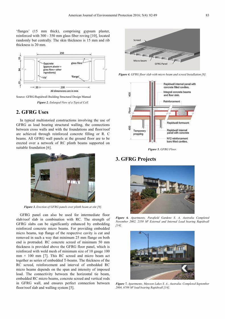
‘flanges’ (15 mm thick), comprising gypsum plaster,
reinforced with 300 - 350 mm glass fiber roving [10], located
randomly but centrally. The skin thickness is 15 mm and rib
thickness is 20 mm.
Source: GFRG/Rapidwall Building Structural Design Manual
Figure 2. Enlarged View of a Typical Cell.
2. GFRG Uses
In typical multistoried constructions involving the use of
GFRG as load bearing structural walling, the connections
between cross walls and with the foundations and floor/roof
are achieved through reinforced concrete filling or R. C
beams. All GFRG wall panels at the ground floor are to be
erected over a network of RC plinth beams supported on
suitable foundation [6].
Figure 3. Erection of GFRG panels over plinth beam at site [9].
GFRG panel can also be used for intermediate floor
slab/roof slab in combination with RC. The strength of
GFRG slabs can be significantly enhanced by embedding
reinforced concrete micro beams. For providing embedded
micro beams, top flange of the respective cavity is cut and
removed in such a way that minimum 25 mm flange on both
end is protruded. RC concrete screed of minimum 50 mm
thickness is provided above the GFRG floor panel, which is
reinforced with weld mesh of minimum size of 10 gauge 100
mm × 100 mm [7]. This RC screed and micro beam act
together as series of embedded T-beams. The thickness of the
RC screed, reinforcement and interval of embedded RC
micro beams depends on the span and intensity of imposed
load. The connectivity between the horizontal tie beam,
embedded RC micro beams, concrete screed and vertical rods
in GFRG wall, and ensures perfect connection between
floor/roof slab and walling system [5].
Figure 4. GFRG floor slab with micro beam and screed Installation [8].
Figure 5. GFRG Floor.
3. GFRG Projects
Figure 6. Apartments, Parafield Gardens S. A, Australia Completed
November 2002, 2350 M² External and Internal Load bearing Rapidwall
[14].
Figure 7. Apartments, Mawson Lakes S. A., Australia. Completed September
2004, 6709 M² load bearing Rapidwall [14].

84 Mohamed Said Meselhy ElSaeed: Development for Sustainable Construction System Glass Fiber
Reinforced Gypsum (GFRG) in Egypt Using Nanotechnology
Figure 8. Apartment Residences, West Beach S. A., Australia. Completed
November 2005, 910 M² Load bearing external and internal Rapidwall [14].
Figure 9. Holliday Housing, New Caledonia Completed March 2009, 3800
M² Load bearing external & internal Rapid wall [14].
4. Thermal Comparison Between
Traditional Work and GFRG
Traditional system is meant to be masonry work (Hollow
brick units) in addition to concrete slabs, covered with plaster
(Cement plaster). The dimensions for bricks and plaster will
be considered as schedule below. This paper will study
thermal performance for different cases for traditional system
as schedule below, using the following U-Value equations.
This study was applied upon base model using software
"Design Builder"; the dimension for this base model is 3 m
width, 3 m length and 3 m height.
4.1. U-Value Calculations
U = 1/Rt
U = U-Value (W/m2. C)
Rt = Overall Thermal Resistance (m2. C/W)
Rt = Ro + Σ R + Ri
Ro = Outer Air-Film Resistance = 0.055 m2. C/W
Ri = Inner Air-Film Resistance = 0.123 m2. C/W
R = L / K
L = Material Width (m)
K = Thermal Conductivity (W/m. C)
Rt = Ro + ∑ R + Ri
= 0.055 + L1/K1 + L2/K2 + …… + Ln/Kn + 0.123
Table 1. U-Value Analysis for Traditional systems (12 mm), (25 mm) & GFRG.
Wall Material Layers L (m) K (W/m. C) R=L/K Rt (m2. C/W) U-Value (W/m2. C)
Traditional System (12 cm)
Outer air-film 0.055
0.42 2.38
Cement plaster 0.02 0.95 0.021
Hollow brick units 0.12 0.60 0.20
Cement plaster 0.02 0.95 0.021
Inner air-film 0.123
Traditional System (25 cm)
Outer air-film 0.055
0.636 1.57
Cement plaster 0.02 0.95 0.021
Hollow brick units 0.25 0.60 0.416
Cement plaster 0.02 0.95 0.021
Inner air-film 0.123
GFRG System
Outer air-film 0.055
0.312 3.20 Gypsum plaster 0.0145 0.42 0.0345
Concrete 0.094 1.44 0.065
Gypsum plaster 0.0145 0.42 0.0345
Inner air-film 0.123
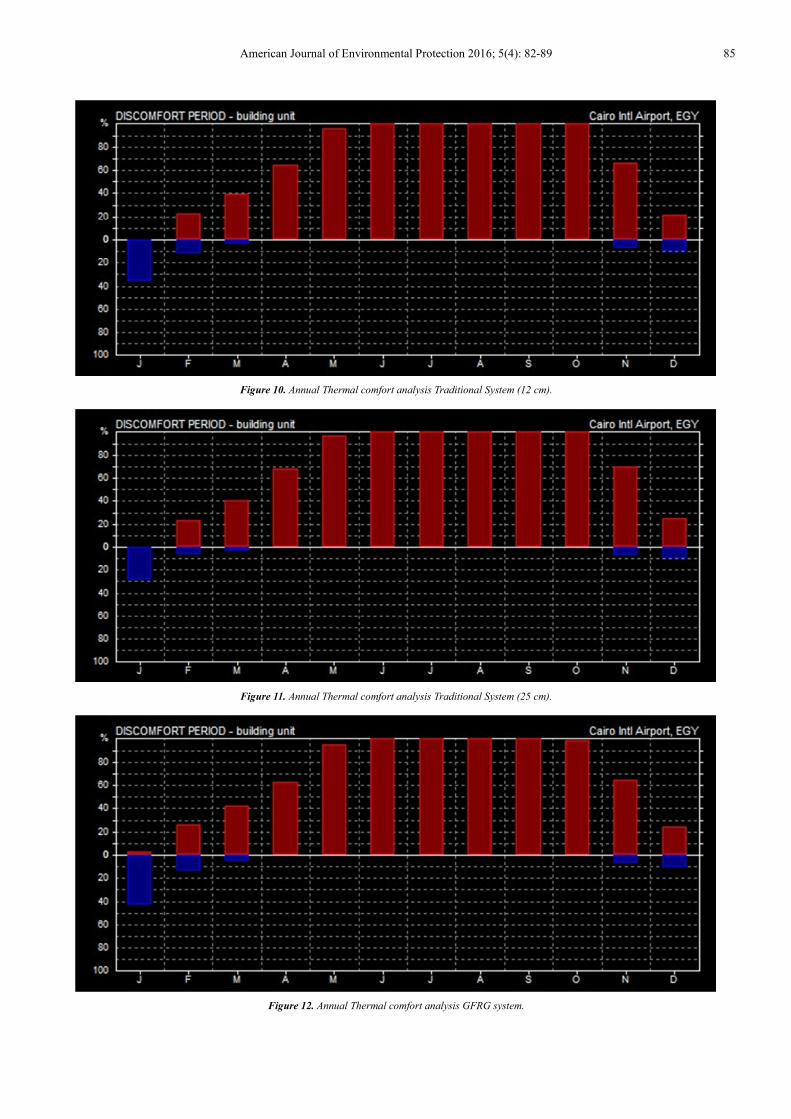
Table 2. Annual Thermal comfort analysis for Traditional system (12 mm).
Wall 1
Month Discomfort
Comfort Hot Cold
1 January 0% 35% 65%
2 February 22% 11% 67%
3 March 39% 4% 57%
4 April 67% 0% 33%
5 May 95% 0% 5%
6 June 100% 0% 0%
7 July 100% 0% 0%
8 August 100% 0% 0%
9 September 100% 0% 0%
10 October 100% 0% 0%
11 November 67% 8% 25%
12 December 21% 10% 69%
American Journal of Environmental Protection 2016; 5(4): 82-89 85
Figure 10. Annual Thermal comfort analysis Traditional System (12 cm).
Figure 11. Annual Thermal comfort analysis Traditional System (25 cm).
Figure 12. Annual Thermal comfort analysis GFRG system.

86 Mohamed Said Meselhy ElSaeed: Development for Sustainable Construction System Glass Fiber
Reinforced Gypsum (GFRG) in Egypt Using Nanotechnology
Figure 13. Thermal Comfort Analysis.
Figure 13 shows that there is no remarkable difference
between different systems studied above, so it is required to
have additional input to have remarkable impact upon
thermal comfort zone for the base model.
Table 3. Annual Thermal comfort analysis for Traditional system (25 mm).
Wall 2
Month Discomfort
Comfort Hot Cold
1 January 0% 29% 71%
2 February 24% 7% 69%
3 March 40% 2% 58%
4 April 69% 0% 31%
5 May 97% 0% 3%
6 June 100% 0% 0%
7 July 100% 0% 0%
8 August 100% 0% 0%
9 September 100% 0% 0%
10 October 100% 0% 0%
11 November 70% 8% 22%
12 December 28% 10% 62%
Table 4. Annual Thermal comfort analysis GFRG system.
Wall 3
Month Discomfort
Comfort Hot Cold
1 January 2% 41% 57%
2 February 28% 14% 58%
3 March 41% 5% 54%
4 April 62% 0% 38%
5 May 95% 0% 5%
6 June 100% 0% 0%
7 July 100% 0% 0%
8 August 100% 0% 0%
9 September 100% 0% 0%
10 October 99% 0% 1%
11 November 65% 8% 27%
12 December 25% 10% 65%
4.2. Nanotechnology in Construction
Nanotechnology and nanomaterials offer interesting new
opportunities in the construction industry and architecture,
for example through the development of very durable, long-
lived and at the same time extremely lightweight construction
materials. Novel insulation materials with very good
insulation values are already available on the market, enable
a thermal rehabilitation of buildings in which conventional
insulation is not possible, and can help to improve energy
efficiency [11]. A wide range of methods for the treatment of
surfaces is also available, including glass, masonry, wood or
metal; the goal is to improve functionalities as well as extend
the lifetime of the materials. Such surface coatings also
promise to conserve resources, for example water, energy and
cleaning agents. Although the research sector has been
reporting intensively about new Nano-technological
developments, the reality shows that “Nano-products” in the
construction industry continue to play a subordinate role and
currently merely occupy niche markets. The construction
business is considered to be conservative, and innovations
often have a difficult time breaking into the market. One of
the main reasons for this is the continued high prices.
Currently, nanomaterials – and therefore “Nano-products” –
are still considerably more expensive than the conventional
alternatives due to the required production technology.
Construction materials are generally used in large amounts:
small price differences can enormously increase overall costs
when considering the total volume of a building or other
structure. Moreover, the technical performance of new
products must first be demonstrated. In buildings, the
calculated time spans are in the range of 20 to 30 years,
making it difficult for example to apply a coating with a
durability of only 1 to 3 years [12]. Longer-term, practical
experience with many Nano-products is still lacking, and we
simply know too little about their product life. Accordingly,
the construction industry for the time being prefers to rely on
proven, conventional products. Nano-technological
applications and products, their availability and their
performance in the construction industry are currently very
limited. A survey conducted in 2009 in the European
construction sector showed that most respondents (�75%)
were unaware of whether they were working with “Nano-
products” or not. This is also partly because there is no
mandatory labeling of nanomaterials in building materials:
the prefix “Nano” – like in many other branches – is used in
advertising a product only if the manufacturers have justified
hopes of improved sales. Often, it is not evident to users
whether a Nano-product actually contains nanomaterials,
what nanomaterials might be involved and in what amounts
they may be present. Not all products that feature the term
“Nano” actually contain nanomaterials. Often, the term
“Nano” merely refers to structures in the Nano size range, for
example the pore size of a particular material, or to the size
of structures that form when a mortar hardens. The use of the
designation “Nano” in product claims and advertising has
again been declining in recent years [12].
4.3. Aerogel Nanomaterials
Nano technology materials are now have great impact
upon construction and design phase, Aerogel is considered
one of the nanotechnology materials that participated in
construction industry. Aerogels are highly porous solid
materials which can consist of 99% air [1]. Aerogel is an
excellent hypervelocity space debris capture medium due to
the fact that it is a highly porous material with a tortuous
microstructure made up of Nano-scale particles forming
aggregates. [13]. Comparable to an ultra-fine sponge, this
American Journal of Environmental Protection 2016; 5(4): 82-89 87
miracle material has its origin – like many other inventions –
in space technology. As highly efficient insulators and
extremely fine filters, aerogels have made important
contributions to space research for years. Aerogel material
can be used as aerogel tiles and aerogel granulate [4].
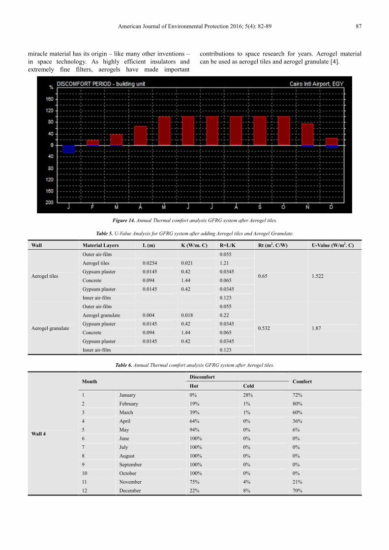
Figure 14. Annual Thermal comfort analysis GFRG system after Aerogel tiles.
Table 5. U-Value Analysis for GFRG system after adding Aerogel tiles and Aerogel Granulate.
Wall Material Layers L (m) K (W/m. C) R=L/K Rt (m2. C/W) U-Value (W/m2. C)
Aerogel tiles
Outer air-film 0.055
0.65 1.522
Aerogel tiles 0.0254 0.021 1.21
Gypsum plaster 0.0145 0.42 0.0345
Concrete 0.094 1.44 0.065
Gypsum plaster 0.0145 0.42 0.0345
Inner air-film 0.123
Aerogel granulate
Outer air-film 0.055
0.532 1.87
Aerogel granulate 0.004 0.018 0.22
Gypsum plaster 0.0145 0.42 0.0345
Concrete 0.094 1.44 0.065
Gypsum plaster 0.0145 0.42 0.0345
Inner air-film 0.123
Table 6. Annual Thermal comfort analysis GFRG system after Aerogel tiles.
Wall 4
Month Discomfort
Comfort Hot Cold
1 January 0% 28% 72%
2 February 19% 1% 80%
3 March 39% 1% 60%
4 April 64% 0% 36%
5 May 94% 0% 6%
6 June 100% 0% 0%
7 July 100% 0% 0%
8 August 100% 0% 0%
9 September 100% 0% 0%
10 October 100% 0% 0%
11 November 75% 4% 21%
12 December 22% 8% 70%

88 Mohamed Said Meselhy ElSaeed: Development for Sustainable Construction System Glass Fiber
Reinforced Gypsum (GFRG) in Egypt Using Nanotechnology
Table 7. Annual Thermal comfort analysis GFRG system after Aerogel Granulate.
Wall 4
Month Discomfort
Comfort Hot Cold
1 January 0% 35% 65%
2 February 15% 5% 74%
3 March 34% 0% 61%
4 April 58% 0% 42%
5 May 94% 0% 6%
6 June 100% 0% 0%
7 July 100% 0% 0%
8 August 100% 0% 0%
9 September 100% 0% 0%
10 October 100% 0% 0%
11 November 63% 8% 29%
12 December 16% 118% 73%
Figure 15. Annual Thermal comfort analysis GFRG system after Aerogel Granulate.
Figure 16. Thermal Comfort Performance.
5. Conclusion
1. After adding aerogel materials (tiles and granulate), the
thermal comfort performance is slightly improved
during the period from November to April. This
improvement was below our expectations for thermal
comfort performance.
2. When we compared traditional system with GFRG
system, the thermal comfort performance was almost
the same;
3. Thermal conductivity factor in GFRG was higher than
expected due to filling of concrete to the cavity of
GFRG system in external walls especially.
4. Structural analysis need to be considered in next studies
in this field, in order to minimize the usage of concrete
filling in different walls in GFRG system.
5. Despite the usage of nanotechnology materials to adapt
thermal comfort performance for materials, we must not
ignore the sustainable treatments for thermal comfort.
References
[1] Aerogel brochure, HECK Wall Systems GmbH & Co. KG, Tholauer Strabe 25, 95615 Marktredwitz, Germany.
[2] GFRG/RAPIDWALL BUILDING, STRUCTURAL DESIGN MANUAL, Building Materials & Technology Promotion Council, Ministry of Housing & Urban Poverty Alleviation, Government of India, December 2011.

American Journal of Environmental Protection 2016; 5(4): 82-89 89
[3] Rapidwall installation manual, Building Materials & Technology Promotion Council, Ministry of Housing & Urban Poverty Alleviation, Government of India, December 2011.
[4] Energy Efficient Sustainable Construction - AEROGELS - Super insulating Building Materials, TECNALIA, Parque Científico y Tecnológico de Bizkaia C/ Geldo, Edificio 700.
[5] IIT Madras, GFRG Building, Structural Design Manual, Building Materials & Technology Promotion Council, Ministry of Housing & Urban Poverty Alleviation, Government of India, 2011.
[6] GFRG, Engineering Design Guidelines, compiled by Ms Dare Sutton Clarke Engineers, Adelaide, Australia, 2002.
[7] Serc, Evaluation of seismic performance of gypcrete building panels, Structural Engineering Research Centre, Chennai, India, 2002.
[8] Wu, Y. F., the effect of longitudinal reinforcement on the cyclic shear behavior of glass fiber reinforced gypsum wall panels: tests. Engineering Structures, 26 (11): 1633–46, 2004.
[9] Wu, Y. F., the structural behavior and design methodology for a new building system consisting of glass fiber reinforced gypsum panels, Construction and Building Materials, Volume 23, 2905–2913, 2009.
[10] IITM, Material properties and assessment of gypcrete building panels, Indian Institute of Technology, Madras, India; September 2002. Project no. CE/BTCM/2557/2002, 2002.
[11] Leydecker, Sylvia, Nanomaterialien in Architektur, Innenarchitektur und Design: Birkhäuser Verlag, 2008.
[12] Van Broekhuizen, Fleur/Van Broekhuizen, Pieter, Nanoprodukte im europäischen Baugewerbe – Aktueller Sachstand 2009.
[13] Woignier T., Duffours L., Colombel P, and Durin C., Aerogels Materials as Space Debris Collectors, Hindawi Publishing Corporation Advances in Materials Science and Engineering Volume 2013, Article ID 484153, 2013.
[14] Rapidwall Projects list, Materials & Technology Promotion Council, Ministry of Housing & Urban Poverty Alleviation, Government of India, 2009.