development, design and construction of actuator
TRANSCRIPT

Defence R&D Canada – Atlantic
DEFENCE DÉFENSE&
Development, Design and Construction of
Actuator Demonstration Devices that
Operate with Magnetic Shape Memory Alloys
K.J. KarisAllenFACTS Engineering Inc.
FACTS Engineering Inc.PO Box 20039Halifax, Nova Scotia B3R 2K9
Project Manager: K.J. KarisAllen, (902) 477-4062
Contract Number: W7707-042637/001/HAL
Contract Scientific Authorities: Dr. R. Ham-Su, (902) 427-7762Dr. S.P. Farrell, (902) 427-3437
Terms of Release:
The scientific or technical validity of this Contract Report is entirely the responsibility of the contractor and thecontents do not necessarily have the approval or endorsement of Defence R&D Canada.
Contract Report
DRDC Atlantic CR 2005-119
May 2006
Copy No.________
Defence Research andDevelopment Canada
Recherche et développementpour la défense Canada

This page intentionally left blank.

Development, Design and Construction of Actuator Demonstration Devices That Operate with Magnetic Shape Memory Alloys
K.J. KarisAllen FACTS Engineering Inc.
FACTS Engineering Inc. PO Box 20039 Halifax, Nova Scotia B3R 2K9
Project Manager: K.J. KarisAllen (902) 477-4062
Contract: W7707-042637/001/HAL
Contract Scientific Authorities: Dr. R. Ham-Su, (902) 427-7762 Dr. S.P. Farrell, (902) 427-3437
Terms of Release:
The scientific or technical validity of this Contractor Report is entirely the responsibility of the contractor and the contents do not necessarily have the approval or endorsement of Defence R&D Canada.
Defence R&D Canada – Atlantic
Contract Report DRDC Atlantic CR 2005-119 May 2006


DRDC Atlantic CR 2005-119 i
Abstract
Three prototype devices which demonstrate potential applications of magnetic shape memory (MSM) alloys were designed and constructed during this study. The devices included a flow effector micro-actuator for influencing the aerodynamic boundary layer of a propelled projectile, an active vibration damping device for reducing the amplitude and energy associated with mechanical vibration, and an energy harvesting device for converting mechanical energy into electrical energy.
Three MSM micro-actuators were designed and incorporated into a simulated nose-cone insert. The actuators were positioned at 120 degree intervals around the circumference of an approximately 75mm diameter ring (the simulated cross section of a nose-cone). Dynamic performance testing of the micro-actuators indicated that peak to peak linear deflections of approximately 0.64mm (which represented approximately 3.3 percent recoverable strain) were generated by the device.
An active vibration damping device was designed and constructed with a linear load train arrangement. The arrangement facilitated the evaluation of the damping capabilities of a MSM actuator included in the load train. Dynamic impact deflection impact transients were imposed on the load train and were subsequently dampened using feedback and feed-forward control algorithms. Utilizing the feedback control algorithm, the results indicated a reduction of approximately 66 percent for both peak deflection amplitude and waveform energy. Utilizing the feed-forward control algorithm, the results indicated a similar reduction to the feedback control of approximately 66 percent for the peak deflection amplitude. An 85 percent reduction in the waveform energy reduction was observed for the feed-forward control algorithm.
An energy harvesting device was designed and constructed which imposed a mechanical deflection transient on a MSM element which was integrated into a core/coil arrangement. The core/coil/MSM element configuration was biased using rare earth permanent magnets. Experimental evaluation of the device indicated that the mechanical energy received by the assembly was converted to a half-cycle haversine waveform with a peak amplitude of approximately 0.4 V.

ii DRDC Atlantic CR 2005-119
Résumé
Trois prototypes de dispositifs prometteurs pour des applications faisant appel à des alliages à mémoire de forme magnétique (MFM) ont été conçus et fabriqués au cours de cette étude. Ces dispositifs comprenaient un microactionneur d’effecteur d’écoulement permettant de modifier la couche limite autour d’un projectile propulsé, un dispositif actif d’amortissement des vibrations permettant de réduire l’amplitude des vibrations mécaniques et l’énergie qui y est associée, et un dispositif de captage d’énergie permettant de convertir l’énergie mécanique en énergie électrique.
Trois microactionneurs MFM ont été conçus et intégrés à la charge utile de la coiffe d’un projectile. Les actionneurs ont été installés à des intervalles de 120 degrés sur la circonférence d’un anneau d’environ 75 mm de diamètre (coupe transversale simulée de la coiffe d’un projectile). Des essais de performance dynamique menés sur ces microactionneurs ont indiqué que ces dispositifs produisaient des flexions linéaires pic-à-pic d’environ 0,64 mm (ce qui représente une déformation réversible d’environ 3,3 %).
Un dispositif actif d’amortissement a été conçu et fabriqué selon une configuration linéaire de la charge. Cette configuration facilite l’évaluation de la capacité d’amortissement d’un actionneur MFM intégré à cette charge. Cette charge a été soumise à des variations transitoires de flexion provoquées par des impacts dynamiques, lesquelles ont ensuite été amorties au moyen d’algorithmes à rétroaction et sans rétroaction. Avec l’algorithme à rétroaction, on a obtenu une réduction d’environ 66 % de l’amplitude des flexions et de l’énergie de l’onde. Avec l’algorithme sans rétroaction, on a obtenu une réduction similaire d’environ 66 % de l’amplitude des flexions et une réduction de 85 % de l’énergie de l’onde.
On a conçu et fabriqué un dispositif de captage de l’énergie qui imposait des flexions mécaniques transitoires à un élément MSM intégré dans un ensemble âme/rouleau, lequel a été déformé au moyen d’aimants permanents fait d’un métal du groupe des terres rares. Une évaluation expérimentale de ce dispositif a indiqué que l’énergie mécanique reçue par l’ensemble était convertie en une onde haversine d’une demi-période présentant une amplitude maximale de 0,4 V.
DRDC Atlantic CR 2005-119 iii
Executive summary
Background
The Emerging Materials Section of Defence R&D Canada - Atlantic has been developing magnetic shape memory (MSM) materials due to their potential use in defence applications. MSM materials are a class of smart materials that change shape in response to application of a magnetic field or compressive strain through the reorientation of twin variants. This mechanism is ideal for the conversion of magnetic energy into mechanical energy and, conversely, mechanical energy into magnetic energy.
Ni-Mn-Ga-based MSM alloys have attained magnetic field induced strains up to approximately 10% and have a relatively wide operating temperature range, from well below 0oC to above room temperature (25oC), making them very attractive for a variety of applications. The purpose of this contract was to design and construct demonstration devices, which utilize magnetic shape memory alloys as the actuator material to illustrate the potential use of these alloys in the Canadian Forces.
Results
Three prototype devices were designed and constructed during this study. The devices included a flow effector micro-actuator for influencing the aerodynamic boundary layer of a missile, an active vibration damping device for reducing the amplitude and energy associated with mechanical vibration, and an energy harvesting device for converting mechanical energy into electrical energy.
Significance
The availability of MSM actuator materials creates new design possibilities for devices and controls. As research in these materials allows them to be fabricated with increased toughness and reliability, new applications and novel devices will emerge. This work gives an exciting glimpse to the defence application possibilities of magnetic shape memory alloys. In particular, it provides some of the initial groundwork for development of a new ‘Technology Investment Fund’ (TIF) project on energy harvesting.
Future Work
Design and development of MSM alloy/polymer composites may improve active damping capabilities and energy harvesting potential over the MSM alloys. A new approach to concurrent design and development of MSM materials and systems (new Energy Harvesting TIF project from April 2006-March 2009) will lead to improved efficiency for these and other systems pertinent to the Canadian Forces.
KarisAllen, K.J. 2006. Development, Design and Construction of Actuator Demonstration Devices That Operate with Magnetic Shape Memory Alloys. DRDC Atlantic CR 2005-119. Defence R&D Canada – Atlantic.
iv DRDC Atlantic CR 2005-119
Sommaire
Introduction
La Section des nouveaux matériaux de RDDC Atlantique a mis au point des matériaux à mémoire de forme magnétique (matériaux MFM), en raison de leur application éventuelle dans le domaine de la défense. Ces matériaux constituent une classe de matériaux intelligents qui changent de forme, lorsqu’on les soumet à un champ magnétique ou à une contrainte de compression, par réorientation des macles variantes. Ce mécanisme est idéal tant pour convertir l’énergie magnétique en énergie mécanique que pour convertir l’énergie mécanique en énergie magnétique.
Les alliages MFM à base de Ni-Mn-Ga peuvent subir des déformations pouvant atteindre environ 10 % lorsqu’on applique un champ magnétique, et ce, dans une plage de températures relativement large allant d’une température bien inférieure à 0oC jusqu’à la température ambiante (25oC); ces alliages sont donc très intéressants pour un grand nombre d’applications. Le but de ce contrat était de concevoir et de fabriquer des dispositifs de démonstration comportant des alliages MFM comme matériaux actionneurs, afin d’illustrer l’utilisation potentielle de ces alliages par les Forces Canadiennes.
Résultats
Trois prototypes ont été conçus et fabriqués au cours de cette étude. Ces dispositifs comprenaient un microactionneur d’effecteur d’écoulement permettant de modifier la couche limite autour d’un projectile, un dispositif actif d’amortissement des vibrations permettant de réduire l’amplitude des vibrations mécaniques et l’énergie qui y est associée, et un dispositif de captage d’énergie permettant de convertir l’énergie mécanique en énergie électrique.
Portée
La disponibilité des matériaux actionneurs à alliage MFM ouvre de nouvelles avenues à la conception de dispositifs et de contrôleurs. Comme la recherche permet de fabriquer ces matériaux en leur conférant une ténacité et une fiabilité accrue, de nouvelles applications et de nouveaux dispositifs devraient voir le jour. Ces travaux donnent un aperçu prometteur des applications possibles des alliages MFM dans le domaine de la défense. Plus particulièrement, ils ouvrent la voie à l’élaboration d’un nouveau projet sur la captage d’énergie qui sera réalisé grâce au Fonds d’investissement technologique (FIT).
Recherches futures
La conception et l’élaboration de composites constitués d’un alliage MSM et d’un polymère permettront peut-être d’améliorer la capacité d’amortissement et le potentiel de captage d’énergie par rapport aux alliages MFM. Il s’agit d’une nouvelle approche comportant la conception et l’élaboration simultanées de matériaux et de systèmes MFM (nouveau projet sur la captage d’énergie qui sera réalisé entre avril 2006 et mars 2009 grâce à un FIT) qui

DRDC Atlantic CR 2005-119 v
permettra d’améliorer l’efficacité de ces systèmes et d’autres systèmes qui intéressent les Forces canadiennes.
KarisAllen, K.J. 2006. Development, Design and Construction of Actuator Demonstration Devices That Operate with Magnetic Shape Memory Alloys. RDDC Atlantique CR 2005-119. R et D pour la défense Canada - Atlantique.
vi DRDC Atlantic CR 2005-119
Table of contents
Abstract........................................................................................................................................ i
Résumé ....................................................................................................................................... ii
Executive summary ................................................................................................................... iii
Sommaire................................................................................................................................... iv
Table of contents ....................................................................................................................... vi
List of figures .......................................................................................................................... viii
1. INTRODUCTION......................................................................................................... 1
1.1 Shape Memory Alloy Technologies ................................................................. 1
2. BACKGROUND........................................................................................................... 2
2.1 General ............................................................................................................. 2
2.2 General Magnetic Circuit Theory..................................................................... 2
3. CONSTRUCTION OF THE MSM DEVICES ............................................................. 5
3.1 Design and Fabrication of the Missile Cone Simulation Device...................... 5
3.1.1 Integral Inductance Coil/MSM Element Housing Design................... 5
3.1.2 Simulated Missile Cone Housing and Magnetic Return Circuit Design 7
3.1.3 Actuator Electronic Driver Hardware/Software Functionality............ 9
3.1.4 Simulated Missile Cone Actuator Experimental Program ................ 10
3.2 Design and Fabrication of the Active Damping Device................................. 10
3.2.1 Mechanical Oscillator Design ........................................................... 11
3.2.2 MSM Actuator/Elastic Element/Deflection Sensor Load Train Design13
3.2.3 Active Damping Hardware/Software Functionality .......................... 15
3.2.4 Active Damping Experimental Program ........................................... 16
3.3 Design and Fabrication of the Energy Harvesting Simulation Device........... 20
3.3.1 Mechanical Oscillator Design ........................................................... 20

DRDC Atlantic CR 2005-119 vii
3.3.2 Integral Coil/MSM Element Housing and Magnetic Return Circuit Design 21
3.3.3 Energy Harvesting Electronic Driver Hardware/Software Functionality................................................................................................... 23
3.3.4 Energy Harvesting Simulation Experimental Program ..................... 24
4. CONCLUSIONS AND RECOMMENDATIONS...................................................... 26
5. References ................................................................................................................... 27
Appendix A - Design Drawings for Missile Cone Actuator Simulation Device...................... 28
Appendix B - Design Drawings for Active Damping Simulation Device................................ 33
Appendix C - Design Drawings for Energy Harvesting Simulation Device ............................ 42
List of symbols/abbreviations/acronyms/initialisms ................................................................ 50
Distribution list ......................................................................................................................... 51

viii DRDC Atlantic CR 2005-119
List of figures
Figure 3.1. Schematic representation of the component arrangement employed for each of the MSM flow effector actuators. ............................................................................................. 6
Figure 3.2. Photograph showing the three assembled integral core/coil/MSM element components subsequent to incorporation into the simulated missile cone housing. ........... 6
Figure 3.3. Photograph showing the Mu metal arms of the magnetic return circuit inserted into the machined cavities of the outer TeflonTM sections.......................................................... 7
Figure 3.4. Photograph showing a front view of the simulated nose-cone insert subsequent to final assembly...................................................................................................................... 8
Figure 3.5. Photograph showing a side view of the simulated nose-cone insert subsequent to final assembly...................................................................................................................... 8
Figure 3.6. Bitmap showing the main GUI associated with the nose-cone actuator software.... 9
Figure 3.7. Still frame from video showing micro flow effector in the non-actuated position. 10
Figure 3.8. Still frame from video showing micro flow effector in the actuated position........ 10
Figure 3.9. Schematic showing the functionality of the active damping device. ..................... 11
Figure 3.10. Photograph showing the basic components of a movable magnet actuator. ........ 12
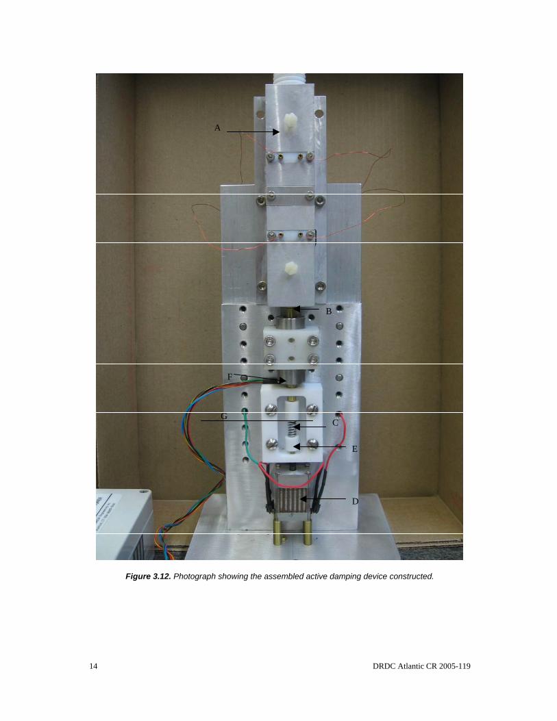
Figure 3.11. Photograph of the fully assembled oscillator used for the active damping device.13
Figure 3.12. Photograph showing the assembled active damping device constructed. ............ 14
Figure 3.13. Bitmap showing the GUI associated with the active damping software. ............. 16
Figure 3.14. Voltage verses time relationship for a typical non-dampened 11 Hz impact transient. ............................................................................................................................ 17
Figure 3.15. Voltage verses time relationship for a typical dampened 11 Hz impact transient using a feedback control algorithm. .................................................................................. 18
Figure 3.16. Voltage verses time relationship for a typical dampened 11 Hz impact transient using a feed-forward control algorithm............................................................................. 18
Figure 3.17. Schematic representation of the functionality for the MSM energy harvesting device. ............................................................................................................................... 21
Figure 3.18. Photograph of the fully assembled oscillator used for the energy harvesting device. ............................................................................................................................... 21
DRDC Atlantic CR 2005-119 ix
Figure 3.19. Photograph of the energy harvesting device constructed. .................................... 22
Figure 3.20. Bitmap showing the main software GUI used for the energy harvesting device. 23
Figure 3.21. Relationship for the voltage generated by the energy harvesting coils. ............... 24
Figure 3.22. Isolated voltage relationship associated with the MSM element impact transient.25
Figure A.1. TeflonTM coil spool with integral MSM actuator crystal housing guide. .............. 28
Figure A.2. Internal aluminum block for locating the bottom plane of the TeflonTM coil spools.28
Figure A.3. TeflonTM outer housing with excavations for the lateral positioning of the coil spools, as well as the positioning of the electromagnet return circuit components........... 29
Figure A.4. Aluminum blocks for adjusting the compression force on the ends of the electromagnet return circuit as well as TeflonTM insulation/spacer blocks between the Al blocks and the return circuit. ............................................................................................. 29
Figure A.5. Electromagnet core configuration (PermendurTM cores slide into the ends of the coil spool).......................................................................................................................... 30
Figure A.6. Electromagnet return circuit components (Mu metal)........................................... 30
Figure A.7. Aluminum base of the stand for the missile cone simulation device. ................... 31
Figure A.8. Vertical support member and support to cone coupling for the missile cone stand.31
Figure A.9. Aluminum bend bar spring for return displacement of MSM single crystal actuator. ............................................................................................................................. 32
Figure B.1. NylonTM LVDT coil placement fixture.................................................................. 33
Figure B.2. Aluminum base for vertical attachment stand. ...................................................... 33
Figure B.3. Aluminum vertical plate for sensor and actuator attachment. ............................... 34
Figure B.4. Modifications to Figure B.3 with increased LVDT attachment points.................. 34
Figure B.5. Aluminum vertical gusset plate between base plate and vertical stand. ................ 35
Figure B.6. Threaded brass couplings between MSM actuator to base and MSM actuator to LVDT core (LVDT calibration configuration). ................................................................ 35
Figure B.7. Aluminum micrometer bracket (LVDT calibration configuration)....................... 36
Figure B.8. Aluminum bracket for the alignment of the NylonTM LVDT fixture block (LVDT calibration configuration). ................................................................................................. 36
x DRDC Atlantic CR 2005-119
Figure B.9. TeflonTM coil spool for movable magnet actuator (centres coils in actuator housing)............................................................................................................................. 37
Figure B.10. Aluminum side mount housing for movable magnet actuator............................. 37
Figure B.11. Brass plunger (load train attachment) for movable magnet actuator................... 38
Figure B.12. TeflonTM linear plunger guide and spring compression adjustment plug for movable magnet actuator. ................................................................................................. 38
Figure B.13. Aluminum collar for centring TeflonTM coil spool in the movable magnet actuator. ............................................................................................................................. 39
Figure B.14. TeflonTM collar for fixing ends of the coil spool combined with insulated wire guides for the spool coils................................................................................................... 39
Figure B.15. Vertical extension support for the attachment of the side-mount movable magnet actuator. ............................................................................................................................. 40
Figure B.16. LVDT core couplings (active damping configuration). ...................................... 40
Figure B.17. TeflonTM housings for positioning load train spring (active damping configuration). ................................................................................................................... 41
Figure B.18.TeflonTM load train journal guides........................................................................ 41
Figure C.1. Aluminum end mount housing for movable magnet actuator. .............................. 42
Figure C.2. Brass plunger (load train attachment) for movable magnet actuator..................... 42
Figure C.3. TeflonTM linear plunger guide and spring compression adjustment plug for movable magnet actuator. ................................................................................................. 43
Figure C.4. Aluminum collar for centering TeflonTM coil spool in the movable magnet actuator. ............................................................................................................................. 43
Figure C.5. TeflonTM collar for fixing ends of the coil spool combined with insulated wire guides for the spool coils................................................................................................... 44
Figure C.6. TeflonTM coil spool for movable magnet actuator (centres coils in actuator housing)............................................................................................................................. 44
Figure C.7. Energy harvesting core and magnetic return circuit end components (Mu metal cores slide into the ends of the MSM actuator block). ...................................................... 45
Figure C.8. Side pieces on the bottom drawing show the arms for the return of the magnetic circuit................................................................................................................................. 45

DRDC Atlantic CR 2005-119 xi
Figure C.9. TeflonTM housing for the MSM single crystal actuator with slots for inserting the coil cores into the ends. ..................................................................................................... 46
Figure C.10. Aluminum base for the attachment of the various energy harvesting device components. ...................................................................................................................... 46
Figure C.11. Inner TeflonTM coil spool end stops..................................................................... 47
Figure C.12. Outer TeflonTM coil spool end stops. ................................................................... 47
Figure C13. End aluminum brackets for supporting the coil and magnetic return circuit........ 48
Figure C.14. Middle support bracket for attaching the movable magnet actuator. .................. 48
Figure C.15. TeflonTM guide block for transmitting impact from movable magnet actuator to MSM single crystal. .......................................................................................................... 49

xii DRDC Atlantic CR 2005-119
This page intentionally left blank.
DRDC Atlantic CR 2005-119 1
1. INTRODUCTION
1.1 Shape Memory Alloy Technologies Shape memory alloys are a class of materials which experience significant dimensional change in response to various external stimuli. Early work on the shape memory effect by the US Naval Ordinance Laboratory focused on an equiatomic alloy of nickel and titanium (Nitinol) [1]. This alloy can effect dimensional change owing to a highly ordered temperature dependent phase transformation between martensite and austenite. Upon heating, the transformation cycle is activated at a critical temperature termed the austenite start temperature (As) and continues to transform with increased temperature until the austenite finish temperature (Af). Upon cooling from Af, the alloy transforms back to martensite (Ms and Mf) at temperatures approximately 20-30 oC lower than the corresponding heating portion of the cycle, thus generating a temperature dependent transformation hysteresis. Over a temperature range bracketing the austenite finish temperature, this alloy can sustain significant recoverable (pseudoelastic) strains in the order of 5-8 percent through the generation of strain-induced martensite and the movement of twin boundaries. This is compared to conventional metallic alloys systems which deform by irrecoverable dislocation slip at strains exceeding approximately 0.2 percent strain. The unique pseudoelastic effect possessed by this class of alloys combined with the highly ordered nature of the temperature dependent phase transformation provides the ability to preprogram or “train” these alloys to assume differing dimensional specifications through control of the applied temperature. Recently, significant work has focused on the development and characterization of ferromagnetic shape memory alloys such as Ni-Mn-Ga [2,3]. For specific compositions, Ni-Mn-Ga alloys exhibit magnetostrictive deflections through twin boundary movement, as compared to magnetostrictive alloys which deflect owing to magnetic domain alignment. Similar to Ni-Ti shape memory alloys, twin boundary movement can facilitate large recoverable pseudoelastic strains in this alloy in the order of 10 percent. Since the change in shape is controlled by an applied magnetic field, the frequency response of the “shape change” of this alloy is significantly increased over temperature controlled alloys. Large displacement, high frequency applications such as active vibration damping, pulse generation, and electromechanical actuators are feasible with these alloys. Over the past several years, DRDC Atlantic has embarked on a program for the assessment of MSM materials for utilization in military applications [3]. To date, the DRDC program has focused primarily on the development of alloy specifications which exhibit ferromagnetic induced strain. Several studies have also been conducted which have assessed the performance characteristics with respect to alloy composition. The primary objective of the current study is the design and development of three devices which demonstrate the potential use of MSM materials in military applications. Applications identified by DRDC include the use of a MSM element as a microactuator which modifies the aerodynamic boundary layer in high velocity projectiles, the use of a MSM element as an actuator for the active damping of mechanical vibration, and the use of a MSM element in a magnetic circuit which converts mechanical energy to electrical energy.

2 DRDC Atlantic CR 2005-119
2. BACKGROUND
2.1 General MSM actuators are comprised of two main components, namely, a magnetic circuit and a mechanical load train. The magnetic circuit functions to apply a magnetic field to the MSM element that generates a pseudoelastic strain in the element. Magnetic fields can be generated by either DC field permanent magnets or by the use of coil electromagnetic devices. Ferromagnetic cores can be used to increase and concentrate the magnetic field applied to the MSM element. If an electromagnetic coil device is employed, the magnitude of the magnetic field is dependent on the applied coil current. For control circuits, while either voltage or current sources may be employed, current sources are often preferred due to the increased time lag associated with voltage sources owing to the inductive properties of the coil. Geometric considerations of the MSM element load train depend on the end-use application of the device (linear, bend, or torque actuation). For the requirements of the current study, linear actuation of the MSM element will be employed in the design of the simulation devices. In this embodiment, one end of the MSM element is attached to a fixed reaction point on the actuator housing. The free end of the MSM element generates actuator deflections dependent on the magnitude of the applied magnetic field strength. The magnitude of the actuator deflection is dependent on several parameters including applied command frequency, system time lags (both electrical and mechanical), and the magnitude of actuator forces (both static and dynamic). Owing to material properties, an elastic element such as a spring is normally included in series with the actuator to return it to its pre-deformed position. The following section provides the general theory used to develop the magnetic circuits incorporated into the devices constructed during this study.
2.2 General Magnetic Circuit Theory Either permanent magnets or electromagnetic devices may be employed for the generation of the magnetic field on the MSM element dependent on the application. For applications which require either an adjustable or dynamic mechanical response of the MSM element, electromagnetic devices are normally utilized. Typically, electromagnetic devices are driven by the induced field generated by a wire wound coil in combination with a ferromagnetic core. The inductance (L) of a coil/core combination is, in general, a measure of the stored energy in the induced magnetic field. The inductance generated by a multi-layered wire wound core with a square winding cross section (i.e. ratio of the winding depth/length ≈ 1) can be approximated by: (2.1) where N is the number of turns in the winding and Rm is the reluctance of the core material magnetic circuit. The magnetomotive force (Fm) generated by a coil is related to the number of turns by:
mRNL
2
=
DRDC Atlantic CR 2005-119 3
(2.2)
where I is the magnitude of the coil current. The magnetomotive force (Fm) is also related to the reluctance of the core material by:
(2.3) where Φ is the magnitude of the flux vector. Combining equations 2.2-2.3 yields:
(2.4) The magnetic field strength (H) is also related to the magnetomotive force by:
(2.5) where le is the effective magnetic path length. The actuation of a MSM element is related to the magnitude of the flux density (B) applied within an element insertion gap. The flux density is related to the flux by:
(2.6) where Ae is the projected area of the core/MSM element interface. Flux density is also related to field strength by:
(2.7)
where μ is the permeability of the material within the magnetic field. Thus, circuit reluctance (Rm) is related to the permeability by:
(2.8) where lc, Ac and μc represent the effective length, effective cross-sectional area, and permeability of the components comprising the magnetic circuit, respectively. Thus, both equation 2.4 and 2.7 suggest that the flux density within the element insertion gap is a function of the effective reluctance of the magnetic circuit which, in turn, is dependent on the permeability of the individual components comprising the circuit. The relationship between applied magnetic field and permeability of ferromagnetic materials is typically non-linear. The permeability relationship results in an asymptotic relationship between B and H with increased applied magnetic field above a certain magnitude (saturation). Thus, in configuring a magnetic circuit, while the utilization of initially high permeability materials increases the efficacy with respect to flux transmission, the designer must also consider the effects of saturation with increased magnetic field strengths. The equivalency of equation 2.3 to V=IR in electric circuit theory indicates that the reluctance associated with individual components comprising a magnetic circuit can be combined into an equivalent reluctance using Kirchhoff’s circuit laws. Thus, the equivalent reluctance of two components in series is represented by the relationship:
NIFm .=
mm RF .Φ=
mRIN .
=Φ
eAB Φ=
e
m
lFH =
μ.HB =
∑=cc
cm A
lR
μ

4 DRDC Atlantic CR 2005-119
(2.9) Similarly, the equivalent reluctance of two components in parallel is represented by the relationship:
(2.10) The equations presented thus far have represented idealized relationships. Wire wound components may sustain power losses from a number of sources. Sources of power losses can be classified into two broad categories, namely, coil losses and core losses. Coil Losses Sources of coil losses include the ohmic resistance of the wire, dielectric losses through the wire coating, and vibration of the wires owing to magnetically induced forces. Ohmic resistance and dielectric impedance convert electrical energy into thermal energy and are a primary source of heat generation within the coil. Vibration of the coil wires normally results from loosely wound wires and can be minimized through the utilization of tensioned, machine wound coils. Core Losses One source of core losses is magnetic friction losses (hysteresis) owing to the coercive forces sustained by ferromagnetic materials. A second source of core losses are the electric current loops generated within the core (eddy currents) under an induced magnetic field. Both these sources are normally minimized by appropriate material selection combined with core design.
21 RRReq +=
21
111RRReq
+=

DRDC Atlantic CR 2005-119 5
3. CONSTRUCTION OF THE MSM DEVICES
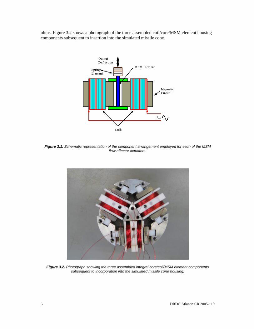
3.1 Design and Fabrication of the Missile Cone Simulation Device Construction of assemblies such as flow effector microactuators demonstrate how low power devices (such as MSM actuators) can be used in the control of the forces generated by high power devices. In the case of microactuators located around the nose-cone of a missile, small changes in the aerodynamic boundary layer conditions of the cone can be used to generate significant changes in the forces (yaw) on the missile body imposed by the rocket motor. The following description details the major components of the devices constructed to simulate how flow effector microactuators may be incorporated into the nose-cone of a propelled projectile. A detailed dimensional description of the various components is provided in Appendix A. In accordance with the proposed requirement, three MSM actuators were designed and incorporated into a simulated nose-cone insert. The actuators were located at 120 degree intervals around the circumference of an approximately 75mm diameter ring (the simulated cross section of a nose-cone insert). Figure 3.1 shows a schematic of the component arrangement employed for the three MSM actuators. Two inductance coils, coaxial to respective ferromagnetic cores were positioned on opposing sides of the MSM element chamber. The orientation of the coil turns to the respective cores, in combination with the orientation of the cores to the MSM element, facilitated the imposition of a flux density vector approximately orthogonal to the longitudinal axis of the MSM element. To return the MSM element to its pre-actuated longitudinal dimension, a mechanical spring element was utilized. Also, a magnetic return circuit was incorporated into the design between the outboard ends of the two ferromagnetic cores to increase the efficacy of the relationship between the imposed coil current and the applied MSM element flux density. The following sections provide physical descriptions of the magnetic circuit components.
3.1.1 Integral Inductance Coil/MSM Element Housing Design For each of the three actuators constructed, an integral coil/ MSM element housing component was designed and machined from TeflonTM. The design (Figure A.1) incorporated a central MSM element housing with a machined vertical slot for the reproducible positioning of the MSM element with respect to the ferromagnetic core elements. Two lateral coil bobbins were also included in the design for maintaining the position and orientation of the coil/core assemblies with respect to the MSM element. A horizontal slot was machined through the bobbin/element housing for the insertion/positioning of the ferromagnetic core which was fabricated using a PermendurTM alloy. PremendurTM was utilized as the core material owing to the combination of high permeability, high saturation flux density and low residual coercive force. Each of the two inductance coils per actuator was fabricated by hand, winding approximately 280 turns of 30 gauge coated speaker wire around the spool bobbin section of the housing component. The ohmic resistance of each coil was measured as approximately 4.0
6 DRDC Atlantic CR 2005-119
ohms. Figure 3.2 shows a photograph of the three assembled coil/core/MSM element housing components subsequent to insertion into the simulated missile cone.
Figure 3.1. Schematic representation of the component arrangement employed for each of the MSM flow effector actuators.
Figure 3.2. Photograph showing the three assembled integral core/coil/MSM element components subsequent to incorporation into the simulated missile cone housing.

DRDC Atlantic CR 2005-119 7
3.1.2 Simulated Missile Cone Housing and Magnetic Return Circuit Design
A section of the nose-cone of a missile was simulated by incorporating the three micro-actuators into an approximately 75 mm diameter x 50 mm long housing. The housing was constructed with three circular sections. The inner (25mm section) and the two outer (12.5mm sections) materials were aluminum and TeflonTM, respectively. Material selection was based on the relatively low permeability of these materials, thus minimizing the potential “cross-talk” between magnetic fields associated with adjacent actuator assemblies. Cavities were machined into the outer TeflonTM sections for the insertion of the Mu metal arms of the magnetic return circuit incorporated into the actuator design (Figure 3.3). Slots were also machined into the outer sections for positioning the integral coil/core/MSM element assembly with respect to the return circuit. The photograph shows one side of the outer TeflonTM section with the coil/core/MSM element assemblies installed. Figure 3.3 also shows the various aluminum components comprising the inner section of the nose-cone housing. The inner section provides attachment points for the outer sections, as well as several setscrews for the final adjustment of the return circuit components with respect to the core subsequent to final assembly of the simulated nose-cone. Figure 3.4 and Figure 3.5 show front and side views of the nose-cone section subsequent to final assembly.
Figure 3.3. Photograph showing the Mu metal arms of the magnetic return circuit inserted into the machined cavities of the outer TeflonTM sections.

8 DRDC Atlantic CR 2005-119
Figure 3.4. Photograph showing a front view of the simulated nose-cone insert subsequent to final assembly.
Figure 3.5. Photograph showing a side view of the simulated nose-cone insert subsequent to final assembly.

DRDC Atlantic CR 2005-119 9
3.1.3 Actuator Electronic Driver Hardware/Software Functionality Three hardware/software drivers were employed for the independent actuation of each of the MSM assemblies. The actuator software is a generic package designed for general pulse width control applications. It is designed around several control buttons which the user may utilize to define the frequency of the mechanical oscillation desired (Figure 3.6). The user may increase or decrease the frequency of the oscillation and then activate the function generator by clicking the “System Status” radio button “On”. The software controls the frequency of TTL square wave pulses generated on pins D0-D2 of the parallel port address defined in the hardware configuration file “config.txt”, which is resident in the software root directory. The duty cycle of the pulse can also be adjusted within the configuration file. If the function generator is activated, adjustment of the imposed frequency requires deactivation of the current pulse wave prior to initialization and activation of an alternative frequency pulse. The frequency modulated pulsed output from the parallel port is bussed into a custom interface board where it provides input to the gate of an E-type MOSFET IC. The source and the drain pins of the MOSFET IC are connected to a 12V DC power supply and the induction coil of the movable magnet oscillator, respectively. The shape of the mechanical oscillation is a function of the inertial properties of the oscillator actuator components and the stiffness constant (k) of the springs which are used to preload the actuator assembly.
Figure 3.6. Bitmap showing the main GUI associated with the nose-cone actuator software.
10 DRDC Atlantic CR 2005-119
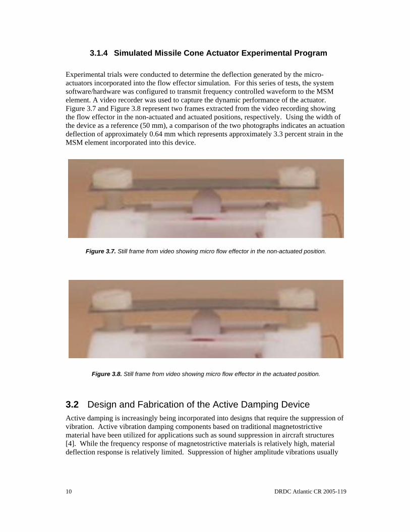
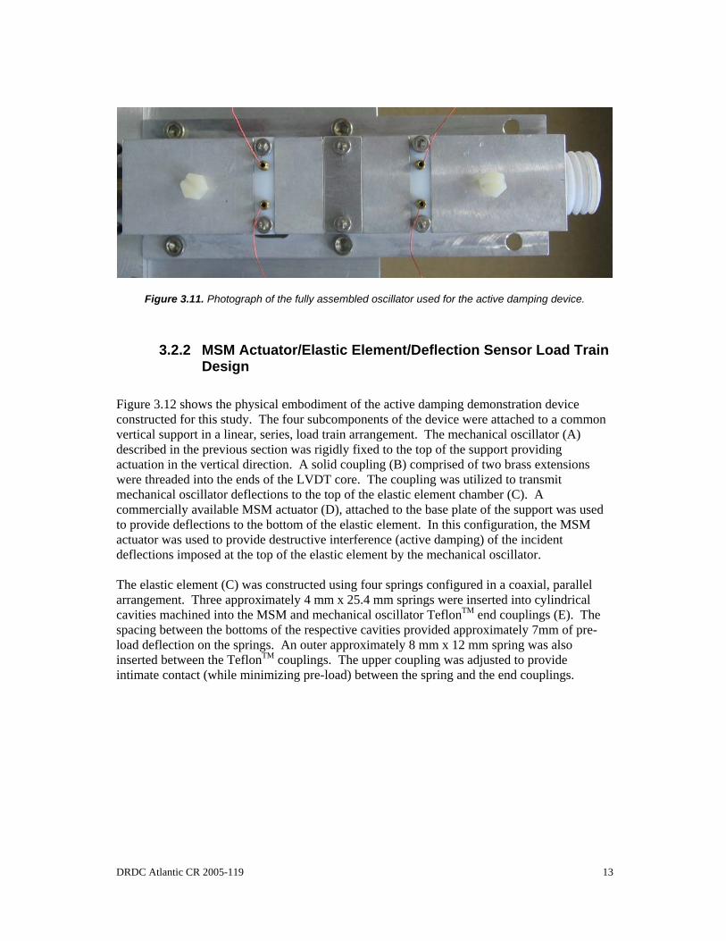
3.1.4 Simulated Missile Cone Actuator Experimental Program Experimental trials were conducted to determine the deflection generated by the micro-actuators incorporated into the flow effector simulation. For this series of tests, the system software/hardware was configured to transmit frequency controlled waveform to the MSM element. A video recorder was used to capture the dynamic performance of the actuator. Figure 3.7 and Figure 3.8 represent two frames extracted from the video recording showing the flow effector in the non-actuated and actuated positions, respectively. Using the width of the device as a reference (50 mm), a comparison of the two photographs indicates an actuation deflection of approximately 0.64 mm which represents approximately 3.3 percent strain in the MSM element incorporated into this device.
Figure 3.7. Still frame from video showing micro flow effector in the non-actuated position.
Figure 3.8. Still frame from video showing micro flow effector in the actuated position.
3.2 Design and Fabrication of the Active Damping Device Active damping is increasingly being incorporated into designs that require the suppression of vibration. Active vibration damping components based on traditional magnetostrictive material have been utilized for applications such as sound suppression in aircraft structures [4]. While the frequency response of magnetostrictive materials is relatively high, material deflection response is relatively limited. Suppression of higher amplitude vibrations usually

DRDC Atlantic CR 2005-119 11
requires sophisticated mechanical amplification techniques when employing traditional magnetostrictive materials. MSM materials offer an increase in the magnetic field generated deflections (typically a 1-2 order of magnitude) while maintaining a relatively high frequency response (typically 100-1000 Hz) Figure 3.9 shows a schematic representation of the functionality of the MSM active damping demonstration device constructed for this study. It is comprised of four main subcomponents. The first component is a mechanical oscillator which functions to generate a source of cyclic mechanical deflection. The second component is an elastic element through which the mechanical oscillator transmits the imposed cyclic deflection. The third component is a MSM actuator which is used to actively suppress the cyclic deflection in the elastic element. The final component is a deflection or a load sensor which provides a feedback signal to the control algorithm. A detailed dimensional description of the various mechanical components utilized in the construction of the active damping demonstration device is provided in Appendix B. The following sections provide physical descriptions of the components designed and fabricated for the active damping simulation device constructed.
Figure 3.9. Schematic showing the functionality of the active damping device.
3.2.1 Mechanical Oscillator Design Simulation of a mechanical vibration was implemented through a custom designed and fabricated mechanical oscillator. For the frequency range of interest in this study, a movable magnet actuator was employed as the mechanical oscillator. In the case of a movable magnet actuator, the coils are fixed and the magnet is given a single degree of freedom (linear actuator). The amplitude and frequency generated by the actuator are varied by controlling the magnitude and frequency of the current signal imposed on the induction coils.

12 DRDC Atlantic CR 2005-119
Figure 3.10 shows the components associated with the movable magnet actuator constructed for the active damping simulation. A TeflonTM bobbin (A) was machined for mounting the coil windings (B), as well as providing a linear guide for the actuator magnet core (C). Two approximately 250 turn induction coils were wound clockwise (facing the bobbin end) using 30 gauge coated wire into the slots machined at the linear quarter positions of the bobbin. The measured resistance for each coil was approximately 3.8 ohms. The bobbin was subsequently guided into the machined actuator housing (D). During this procedure, the coil attachment wires were routed through the outer wire slots in the housing. The bobbin was fixed in place using the aluminum centering block (E). Coil wires were guided through the holes provided in the two TeflonTM wire guide blocks (F) and the blocks were fixed to the actuator housing. A 0.635 mm diameter by 50 mm long rare earth magnet was positioned into the bobbin. The two actuator end caps were constructed by guiding a spring loaded brass actuator extension (G) through a TeflonTM block (H).
Figure 3.10. Photograph showing the basic components of a movable magnet actuator.
The threaded TeflonTM blocks were turned into the ends of the actuator housing such that the spring loaded ends of the actuator extensions were in intimate contact with the ends of the permanent magnet actuator core. The outboard ends of the actuator extensions were threaded, facilitating the attachment of the device load train. Figure 3.11 shows a photograph of the assembled actuator.
A
B B
C
GH
D
E F
DRDC Atlantic CR 2005-119 13
Figure 3.11. Photograph of the fully assembled oscillator used for the active damping device.
3.2.2 MSM Actuator/Elastic Element/Deflection Sensor Load Train Design
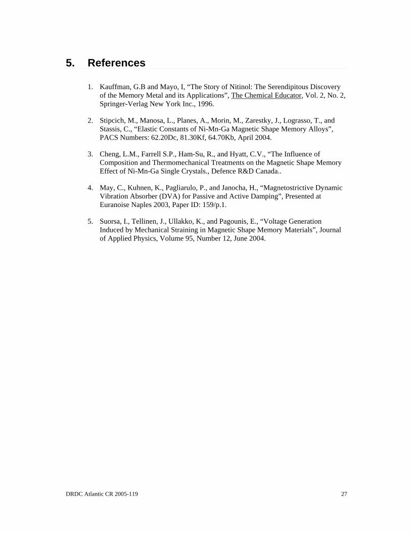
Figure 3.12 shows the physical embodiment of the active damping demonstration device constructed for this study. The four subcomponents of the device were attached to a common vertical support in a linear, series, load train arrangement. The mechanical oscillator (A) described in the previous section was rigidly fixed to the top of the support providing actuation in the vertical direction. A solid coupling (B) comprised of two brass extensions were threaded into the ends of the LVDT core. The coupling was utilized to transmit mechanical oscillator deflections to the top of the elastic element chamber (C). A commercially available MSM actuator (D), attached to the base plate of the support was used to provide deflections to the bottom of the elastic element. In this configuration, the MSM actuator was used to provide destructive interference (active damping) of the incident deflections imposed at the top of the elastic element by the mechanical oscillator. The elastic element (C) was constructed using four springs configured in a coaxial, parallel arrangement. Three approximately 4 mm x 25.4 mm springs were inserted into cylindrical cavities machined into the MSM and mechanical oscillator TeflonTM end couplings (E). The spacing between the bottoms of the respective cavities provided approximately 7mm of pre-load deflection on the springs. An outer approximately 8 mm x 12 mm spring was also inserted between the TeflonTM couplings. The upper coupling was adjusted to provide intimate contact (while minimizing pre-load) between the spring and the end couplings.
14 DRDC Atlantic CR 2005-119
D
G
E
C
B
A
F
Figure 3.12. Photograph showing the assembled active damping device constructed.

DRDC Atlantic CR 2005-119 15
For the load train constructed, the commercial AC LVDT (F) inserted between the mechanical oscillator and the elastic element should provide an accurate description of the deflections imposed at the reference plane of the top TeflonTM end coupling (G). If it is assumed that the stiffness constant (k) of the composite spring assembly remains independent of deflection, the reaction force (P) between the spring and the top end coupling is given by:
(3.1) Since absorbed energy (E) is defined by:
(3.2) Combining equations 3.1 and 3.2 gives:
(3.3) Since the output voltage signal of the LVDT utilized is linear with respect to deflection, for similar time domains, the efficacy of the active damping can be approximated by comparing the area under the transducer voltage/time response for a damped and non-damped system.
3.2.3 Active Damping Hardware/Software Functionality The active damping software is an algorithm designed for general feedback or feed-forward control applications. It is designed around a custom GUI (Figure 3.13) which provides the interface between the user and the software control algorithms. The GUI displays several control buttons, which the user may utilize to define the frequency of the incident mechanical oscillation desired, the control mode, and the control status. The user may increment or decrement the frequency of the oscillation using the scrollbar buttons and subsequently activate the mechanical oscillator function generator by clicking the vibration control radio button “On”. The software controls the frequency of a square waveform generated by a general purpose ISA bus multifunction board. Adjustment of the imposed frequency may be affected while the vibration control is active. Active damping of the cyclic deflection generated by the mechanical oscillator is initiated by activating the active damping control radio button. Prior to activating active damping, the user may select either feedback (FB) or feed-forward (FF) control modes by clicking the corresponding radio button. If feed-forward control is selected, the user may adjust the phase shift between the feedback signal and the output waveform using the scrollbar buttons provided. If feedback control is selected, the user may adjust the proportional gain of the command signal using the scrollbar provided by the “System/System Tuning” selection located on the main menu bar. Based on the control algorithm selected, the software generates the appropriate command signal output to the MSM actuator via the ISA bus multifunction board.
δkP =
( )∫=t
dtPE0
δ
( ) δδ dtkEt
∫=0

16 DRDC Atlantic CR 2005-119
The user may also capture the LVDT sensor signal by clicking the “Capture” button. Once activated, the software will collect the subsequent 25000 pts at a scan rate of approximately 0.2 ms/pt. The user may save the data collected by selecting “Save Shot Data” from the “System” pop-down menu located on the main menu bar. A data box has been included to display the data collected by clicking the “Display” box provided. Custom electronic interface was constructed to convert the function generator and active damping command voltage signals into current controlled outputs to the mechanical oscillator and MSM actuator, respectively. The current range for the mechanical oscillator was approximately 0-1.5 amperes while the range for the MSM actuator was approximately ± 1.0 amperes. The feedback signal from the AC LVDT conditioning electronics was further conditioned through a series of instrumentation amplifiers to provide compatibility with the analog inputs of the ISA multifunction board employed.
Figure 3.13. Bitmap showing the GUI associated with the active damping software.
3.2.4 Active Damping Experimental Program Several experimental trials were conducted to determine the efficacy of the active damping control algorithms for the mechanical device constructed. For this series of tests, the mechanical oscillator was configured to transmit frequency controlled impact transients to the elastic element. It was noted that in this configuration, frequencies in excess of approximately 12 Hz resulted in reflective wave interference with the subsequent impact cycle. The feedback signal from the LVDT was digitized for tests including a non-damped system, active damping using feedback control, and active damping using feed-forward control. The 12 bit signal data for each test was stored for subsequent post-processing. Figure 3.14 shows the voltage verses time transient for a non-dampened cyclic impact frequency of approximately 10 Hz. The waveform exhibits a morphology typical of impact

DRDC Atlantic CR 2005-119 17
transient. The initial deflection peak of the transient results from the transfer of inertial energy from the impact mass to the load train. The minimum value observed subsequent to the initial peak is generated by the reflected inertial stress wave. The second peak represents the deflection associated with the deceleration of the combined impact/load train mass.
Figure 3.14. Voltage verses time relationship for a typical non-dampened 11 Hz impact transient.
Figure 3.15 shows the voltage verses time trace for an impact frequency of approximately 10 Hz where active damping feedback control was implemented through the MSM actuator. Zero volts in this waveform transient represents the set-point voltage for the control algorithm. Comparison of the dampened signal to the non-dampened signal indicates a maximum amplitude ratio (dampened/non-dampened) of approximately 1/3. It has been postulated that the peak positive amplitude observed in the dampened trace results from the magnitude of the incident mechanical oscillator deflection exceeding the capacity of the commercial MSM actuator utilized. Figure 3.16 shows the voltage verses time trace for an impact frequency of approximately 10 Hz where active damping feed-forward control was implemented through the MSM actuator. For this experiment, the feedback signal from the LVDT was also connected to an oscilloscope. A sinusoidal current waveform at the maximum rated capacity of the MSM actuator was imposed to dampen the incident waveform generated by the mechanical oscillator. The sinusoidal waveform was subsequently phase shifted until maximum damping of the feedback was visually observed on the oscilloscope. Figure 3.16 shows the relative position of the sinusoidal waveform with respect to the resulting feedback signal which generated maximum damping. Similar to the feedback control tests conducted, comparison of the dampened signal to the non-dampened signal indicates a maximum amplitude ratio (dampened/non-dampened) of approximately 1/3. The ratio similarity supports the thesis that the peak amplitudes observed in the feedback and feed-forward cases result from the

18 DRDC Atlantic CR 2005-119
deflection capacity of the MSM actuator being insufficient to actively dampen the entire incident waveform generated by the mechanical oscillator.
Figure 3.15. Voltage verses time relationship for a typical dampened 11 Hz impact transient using a feedback control algorithm.
Figure 3.16. Voltage verses time relationship for a typical dampened 11 Hz impact transient using a feed-forward control algorithm.

DRDC Atlantic CR 2005-119 19
An alternative method of accessing the efficacy of the active damping algorithms is to compare the dampened to non-dampened energies. For the tests conducted, a comparison of energies was affected by numerically integrating the area under the respective feedback voltage time curves. The results generated for Figures 3.15-3.16 indicate that while the dampened to non-dampened energy ratio for the feedback control algorithm remains relatively similar to the amplitude ratio (1/3), the energy ratio for the feed-forward control algorithm decreases to approximately 1/6.

20 DRDC Atlantic CR 2005-119
3.3 Design and Fabrication of the Energy Harvesting Simulation Device In the two applications described above, electrical (magnetic) energy is converted to mechanical energy through the deformation response MSM element. Owing to the reversibility of the process, MSM elements also have potential for sensors and electrical energy recovery applications. Potential applications for this embodiment of an MSM element assembly include “trickle chargers” for batteries, mechanical event counters in the field of vibration, and deflection based measurements (velocity, acceleration, etc.). If a constant magnetic field is applied to a MSM element (using a permanent magnet), the element will deform to a steady state condition based on the field strength. The subsequent imposition of a mechanical deflection on the MSM element results in a dimensional change in the element (which results in a change in the reluctance of the core-element air gap). The imposed deflection also generates a change in the MSM material permeability, which results in a variance in the element material reluctance. The net change in the combined reluctance generates a flux in the core material, which can be used to generate a voltage in an external coil. In a study conducted by Suorsa et al [5], voltages near 60 V were observed from relatively small MSM element assemblies. Suorsa et al [5] also observed that the magnitude of the voltage correlated to the rate change in the deformation (velocity) of the MSM element. Figure 3.17 shows a schematic representation of the functionality of the MSM energy harvesting demonstration device constructed for this study. It is comprised of three main subcomponents. The first component was a mechanical oscillator which functioned to generate a source of cyclic mechanical deflection which was imposed on the MSM element. The second component was the MSM element housing chamber which functioned to align the axis of the MSM element with respect to both the incident deflection and the magnetic circuit. The final component is the magnetic circuit and coil assembly which functions to convert the mechanical energy to electrical energy. A detailed dimensional description of the various mechanical components utilized in the construction of the active damping demonstration device is provided in Appendix C. The following sections provide physical descriptions of the components designed and fabricated for the energy harvesting simulation device.
3.3.1 Mechanical Oscillator Design The mechanical oscillator design utilized for the energy harvesting device was constructed with functional components similar to those used for the active damping mechanical oscillator. A detailed description of the individual components was provided previously in section 3.2.1. Variance from the design for the active damping mechanical oscillator included an increase in the number of individual coil turns to approximately 280, generating a resistance of approximately 4.0 ohms. The attachment configuration was also end mounted as opposed to the side mounted oscillator used for the active damping device. Figure 3.18 shows a photograph of the assembled mechanical oscillator incorporated into the energy harvesting device.

DRDC Atlantic CR 2005-119 21
Figure 3.17. Schematic representation of the functionality for the MSM energy harvesting device.
Figure 3.18. Photograph of the fully assembled oscillator used for the energy harvesting device.
3.3.2 Integral Coil/MSM Element Housing and Magnetic Return Circuit Design
Figure 3.19 shows the physical embodiment of the energy harvesting demonstration device constructed for this study. The three subcomponents of the device were attached to a common base support. The mechanical oscillator (A) described in the previous sections was axially centered with respect to the magnetic circuit and was positioned above the MSM element chamber using two vertical supports. A TeflonTM MSM element chamber (B) was machined with a vertical slot for orienting the longitudinal axis of the MSM element in the direction of the deflection vector generated by the mechanical oscillator. Two horizontal slots were machined into the sides of the element chamber to orient two Mu metal core/coil assemblies (C) orthogonal with respect to the longitudinal axis of the MSM element.

22 DRDC Atlantic CR 2005-119
A
C
B
D
Figure 3.19. Photograph of the energy harvesting device constructed.

DRDC Atlantic CR 2005-119 23
The core/coil assembly was wound with approximately 800 turns of 30 gauge coated wire while the second core coil assembly was wound with approximately 1200 turns of wire. The resistance values of the two coils were approximately 18 ohms and 24 ohms. The outboard ends of each of the core/coil assemblies were terminated with rare earth permanent magnets. A magnetic return circuit (D) fabricated from Mu metal was utilized to magnetically connect the outboard sides of the rare earth magnets.
3.3.3 Energy Harvesting Electronic Driver Hardware/Software Functionality
A subset of the active damping software functionality was used to control the mechanical oscillator and acquire data from the energy harvesting coils. Referring to Figure 3.20, the user may increment or decrement the frequency of the imposed mechanical oscillation using the scrollbar buttons and subsequently activate the mechanical oscillator function generator by clicking the vibration control radio button “On”. The software controls the frequency of a square waveform generated by a general purpose ISA bus multifunction board. Adjustment of the imposed frequency may be affected while the vibration control is active. The user may also capture the harvested coil voltage generated by the device by clicking the “Capture” button. Once activated, the software will collect the subsequent 25000 pts at a scan rate of approximately 0.2 ms/pt. The user may save the data collected by selecting “Save Shot Data” from the “System” pop-down menu located on the main menu bar. A data box has been included to display the data collected by clicking the “Display” box provided. A custom electronic interface was constructed to convert the function generator voltage signals into current controlled outputs to the mechanical oscillator. The current range for the mechanical oscillator was approximately 0-1.5 amperes. The voltage signal from the harvesting coils was conditioned using a high impedance, differential instrumentation amplifier prior to routing the signal to the analog inputs of the ISA multifunction board.
Figure 3.20. Bitmap showing the main software GUI used for the energy harvesting device.

24 DRDC Atlantic CR 2005-119
3.3.4 Energy Harvesting Simulation Experimental Program Experimental trials were conducted to determine the coil voltage generated by the energy harvesting device constructed. For this series of tests, the mechanical oscillator was configured to transmit frequency controlled impact transients to the MSM element. Figure 3.21 shows the voltage verses time data generated for an approximately 12 Hz impact transient imposed on the MSM element by the mechanical oscillator. The coil voltage data exhibits two distinctly differing waveform morphologies within each oscillator cycle. The first morphology is an approximately 0-2.5 V DC square wave. Figure 3.21 also indicates that this portion of the waveform is in phase with the square wave command signal imposed on the mechanical oscillator, suggesting it results from the RF signal generated from the mechanical oscillator coil induction. The second morphology is a half-cycle transient which corresponds to the impact transmission events between the oscillator and the MSM element. Figure 3.22 shows one of the impact transients from Figure 3.21. The voltage-time trace approximates a haversine relationship with a peak amplitude of approximately 0.4 V DC.
Figure 3.21. Relationship for the voltage generated by the energy harvesting coils.

DRDC Atlantic CR 2005-119 25
Figure 3.22. Isolated voltage relationship associated with the MSM element impact transient.

26 DRDC Atlantic CR 2005-119
4. CONCLUSIONS AND RECOMMENDATIONS
Three prototype devices which demonstrate potential applications of magnetic shape memory (MSM) alloys were designed and constructed during this study. The devices included a flow effector micro-actuator for influencing the aerodynamic boundary layer of a propelled projectile, an active damping device for reducing the amplitude and energy associated with mechanical vibration, and an energy harvesting device for converting mechanical energy into electrical energy.
Three MSM micro-actuators were designed and incorporated into a simulated nose-cone. The actuators were located at 120 degree intervals around the circumference of an approximately 75 mm diameter ring (the simulated cross section of a nose-cone). Dynamic performance testing of the micro-actuators indicated that peak to peak linear deflections of approximately 0.64 mm (which represented 3.3 percent recoverable strain) were generated by the device.
An active damping device was designed and constructed with a linear load train arrangement. The arrangement facilitated the evaluation of the damping capabilities of a MSM actuator included in the load train. Dynamic impact deflection transients were imposed on the load train and were subsequently dampened using feedback and feed-forward control algorithms. Utilizing the feedback control algorithm, the results indicated a reduction of approximately 66 percent for both peak deflection amplitude and waveform energy. Utilizing the feed-forward control algorithm, the results indicated a similar reduction to the feedback control of approximately 66 percent for the peak deflection amplitude. An 85 percent reduction in the waveform energy was observed for the feed-forward control algorithm.
An energy harvesting device was designed and constructed through the imposition of a mechanical deflection transient on a MSM element which was integrated into a core/coil arrangement. The core/coil/MSM element configuration was biased using rare earth permanent magnets. Experimental evaluation of the device indicated that the mechanical energy received by the assembly was converted to a half-cycle haversine waveform with a peak amplitude of approximately 0.4 V.
DRDC Atlantic CR 2005-119 27
5. References
1. Kauffman, G.B and Mayo, I, “The Story of Nitinol: The Serendipitous Discovery of the Memory Metal and its Applications”, The Chemical Educator, Vol. 2, No. 2, Springer-Verlag New York Inc., 1996.
2. Stipcich, M., Manosa, L., Planes, A., Morin, M., Zarestky, J., Lograsso, T., and Stassis, C., “Elastic Constants of Ni-Mn-Ga Magnetic Shape Memory Alloys”, PACS Numbers: 62.20Dc, 81.30Kf, 64.70Kb, April 2004.
3. Cheng, L.M., Farrell S.P., Ham-Su, R., and Hyatt, C.V., “The Influence of Composition and Thermomechanical Treatments on the Magnetic Shape Memory Effect of Ni-Mn-Ga Single Crystals., Defence R&D Canada..
4. May, C., Kuhnen, K., Pagliarulo, P., and Janocha, H., “Magnetostrictive Dynamic Vibration Absorber (DVA) for Passive and Active Damping”, Presented at Euranoise Naples 2003, Paper ID: 159/p.1.
5. Suorsa, I., Tellinen, J., Ullakko, K., and Pagounis, E., “Voltage Generation Induced by Mechanical Straining in Magnetic Shape Memory Materials”, Journal of Applied Physics, Volume 95, Number 12, June 2004.

28 DRDC Atlantic CR 2005-119
Appendix A - Design Drawings for Missile Cone Actuator Simulation Device
Figure A.1. TeflonTM coil spool with integral MSM actuator crystal housing guide.
Figure A.2. Internal aluminum block for locating the bottom plane of the TeflonTM coil spools.

DRDC Atlantic CR 2005-119 29
Figure A.3. TeflonTM outer housing with excavations for the lateral positioning of the coil spools, as well as the positioning of the electromagnet return circuit components.
Figure A.4. Aluminum blocks for adjusting the compression force on the ends of the electromagnet return circuit as well as TeflonTM insulation/spacer blocks between the Al blocks and the return circuit.

30 DRDC Atlantic CR 2005-119
Figure A.5. Electromagnet core configuration (PermendurTM cores slide into the ends of the coil spool).
Figure A.6. Electromagnet return circuit components (Mu metal).
DRDC Atlantic CR 2005-119 31
Figure A.7. Aluminum base of the stand for the missile cone simulation device.
Figure A.8. Vertical support member and support to cone coupling for the missile cone stand.

32 DRDC Atlantic CR 2005-119
Figure A.9. Aluminum bend bar spring for return displacement of MSM single crystal actuator.

DRDC Atlantic CR 2005-119 33
Appendix B - Design Drawings for Active Damping Simulation Device
Figure B.1. NylonTM LVDT coil placement fixture.
Figure B.2. Aluminum base for vertical attachment stand.
34 DRDC Atlantic CR 2005-119
Figure B.3. Aluminum vertical plate for sensor and actuator attachment.
Figure B.4. Modifications to Figure B.3 with increased LVDT attachment points.

DRDC Atlantic CR 2005-119 35
Figure B.5. Aluminum vertical gusset plate between base plate and vertical stand.
Figure B.6. Threaded brass couplings between MSM actuator to base and MSM actuator to LVDT core (LVDT calibration configuration).

36 DRDC Atlantic CR 2005-119
Figure B.7. Aluminum micrometer bracket (LVDT calibration configuration).
Figure B.8. Aluminum bracket for the alignment of the NylonTM LVDT fixture block (LVDT calibration configuration).

DRDC Atlantic CR 2005-119 37
Figure B.9. TeflonTM coil spool for movable magnet actuator (centres coils in actuator housing).
Figure B.10. Aluminum side mount housing for movable magnet actuator.

38 DRDC Atlantic CR 2005-119
Figure B.11. Brass plunger (load train attachment) for movable magnet actuator.
Figure B.12. TeflonTM linear plunger guide and spring compression adjustment plug for movable magnet actuator.

DRDC Atlantic CR 2005-119 39
Figure B.13. Aluminum collar for centring TeflonTM coil spool in the movable magnet actuator.
Figure B.14. TeflonTM collar for fixing ends of the coil spool combined with insulated wire guides for the spool coils.

40 DRDC Atlantic CR 2005-119
Figure B.15. Vertical extension support for the attachment of the side-mount movable magnet actuator.
Figure B.16. LVDT core couplings (active damping configuration).

DRDC Atlantic CR 2005-119 41
Figure B.17. TeflonTM housings for positioning load train spring (active damping configuration).
Figure B.18.TeflonTM load train journal guides.

42 DRDC Atlantic CR 2005-119
Appendix C - Design Drawings for Energy Harvesting Simulation Device
Figure C.1. Aluminum end mount housing for movable magnet actuator.
Figure C.2. Brass plunger (load train attachment) for movable magnet actuator.

DRDC Atlantic CR 2005-119 43
Figure C.3. TeflonTM linear plunger guide and spring compression adjustment plug for movable magnet actuator.
Figure C.4. Aluminum collar for centering TeflonTM coil spool in the movable magnet actuator.
44 DRDC Atlantic CR 2005-119
Figure C.5. TeflonTM collar for fixing ends of the coil spool combined with insulated wire guides for the spool coils.
Figure C.6. TeflonTM coil spool for movable magnet actuator (centres coils in actuator housing).

DRDC Atlantic CR 2005-119 45
Figure C.7. Energy harvesting core and magnetic return circuit end components (Mu metal cores slide into the ends of the MSM actuator block).
Figure C.8. Side pieces on the bottom drawing show the arms for the return of the magnetic circuit.

46 DRDC Atlantic CR 2005-119
Figure C.9. TeflonTM housing for the MSM single crystal actuator with slots for inserting the coil cores into the ends.
Figure C.10. Aluminum base for the attachment of the various energy harvesting device components.

DRDC Atlantic CR 2005-119 47
Figure C.11. Inner TeflonTM coil spool end stops.
Figure C.12. Outer TeflonTM coil spool end stops.

48 DRDC Atlantic CR 2005-119
Figure C13. End aluminum brackets for supporting the coil and magnetic return circuit.
Figure C.14. Middle support bracket for attaching the movable magnet actuator.

DRDC Atlantic CR 2005-119 49
Figure C.15. TeflonTM guide block for transmitting impact from movable magnet actuator to MSM single crystal.

50 DRDC Atlantic CR 2005-119
List of symbols/abbreviations/acronyms/initialisms
DRDC Defence Research and Development Canada
GUI Graphical User Interface
MSM Magnetic Shape Memory
LVDT Linear Variable Displacement Transducer
D0-D2 Digital Output Pins on Parallel Port Connector
DC Direct Current
AC Alternating Current
MOSFET Metal Oxide Field Effect Transistor
IC Integrated Circuit

DRDC Atlantic CR 2005-119 51
Distribution list DRDC Atlantic CR 2005-119 PART 1: Internal Distribution by DRDC Atlantic
1. DRDC Library 1 hard copy 4 electronic copies
2. Shannon Farrell 3 hard copies 3 electronic copies
3. Rosaura Ham-Su 1 hard copy 1 electronic copy
4. Leon Cheng 1 hard copy 1 electronic copy
5. Royale Underhill 1 electronic copy
6. Calvin V. Hyatt 1 hard copy 1 electronic copy
7. Luke MacGregor 1 hard copy
8. Christopher Purcell 1 hard copy
Total List Part 1 9 hard copies 11 electronic copies
PART 2: External Distribution by DRDKIM 2-2-3
9. DRDKIM 1 electronic copy
10. Ken J. KarisAllen 2 hard copies 1 electronic copy FACTS Engineering Inc. P.O. Box 20039 Halifax, NS B3R 2K9
11. Franklin Wong 1 hard copy DRDC Valcartier 2459 Pie-XI Blvd North Val-Belair, QC G3J 1X5
Total List Part 2 3 hard copies 2 electronic copies
Total Copies Required 12 hard copies 13 electronic copies

This page intentionally left blank.

DRDC Atlantic mod. May 02
DOCUMENT CONTROL DATA(Security classification of title, body of abstract and indexing annotation must be entered when the overall document is classified)
1. ORIGINATOR (the name and address of the organization preparing the document.Organizations for whom the document was prepared, e.g. Centre sponsoring acontractor's report, or tasking agency, are entered in section 8.)
FACTS Engineering Inc.PO Box 20039Halifax, NS B3R 2K9
2. SECURITY CLASSIFICATION !!(overall security classification of the document including special warning terms if applicable).
UNCLASSIFIED
3. TITLE (the complete document title as indicated on the title page. Its classification should be indicated by the appropriate abbreviation (S,C,R or U) in parentheses after the title).
Development, Design and Construction of Actuator Demonstration Devices That Operate withMagnetic Shape Memory Alloys
4. AUTHORS (Last name, first name, middle initial. If military, show rank, e.g. Doe, Maj. John E.)
K.J. KarisAllen
5. DATE OF PUBLICATION (month and year of publication ofdocument)
May 2006
6a. NO. OF PAGES (totalcontaining information IncludeAnnexes, Appendices, etc).50
6b. NO. OF REFS (total citedin document)
5
7. DESCRIPTIVE NOTES (the category of the document, e.g. technical report, technical note or memorandum. If appropriate, enter thetype of report, e.g. interim, progress, summary, annual or final. Give the inclusive dates when a specific reporting period is covered).
CONTRACT REPORT 8. SPONSORING ACTIVITY (the name of the department project office or laboratory sponsoring the research and development. Include address).
Defence R&D Canada – AtlanticPO Box 1012Dartmouth, NS, Canada B2Y 3Z7
9a. PROJECT OR GRANT NO. (if appropriate, the applicable researchand development project or grant number under which the documentwas written. Please specify whether project or grant).
11gm13
9b. CONTRACT NO. (if appropriate, the applicable number underwhich the document was written).
W7707-04-2637/001/HAL 10a ORIGINATOR'S DOCUMENT NUMBER (the official document
number by which the document is identified by the originatingactivity. This number must be unique to this document.)
DRDC Atlantic CR 2005-119
10b OTHER DOCUMENT NOs. (Any other numbers which may beassigned this document either by the originator or by thesponsor.)
11. DOCUMENT AVAILABILITY (any limitations on further dissemination of the document, other than those imposedby security classification)( X ) Unlimited distribution( ) Defence departments and defence contractors; further distribution only as approved( ) Defence departments and Canadian defence contractors; further distribution only as approved( ) Government departments and agencies; further distribution only as approved( ) Defence departments; further distribution only as approved( ) Other (please specify):
12. DOCUMENT ANNOUNCEMENT (any limitation to the bibliographic announcement of this document. This will normally correspond to theDocument Availability (11). However, where further distribution (beyond the audience specified in (11) is possible, a wider announcementaudience may be selected).
DRDC Atlantic mod. May 02
13. ABSTRACT (a brief and factual summary of the document. It may also appear elsewhere in the body of the document itself. Itis highly desirable that the abstract of classified documents be unclassified. Each paragraph of the abstract shall begin with anindication of the security classification of the information in the paragraph (unless the document itself is unclassified) representedas (S), (C), (R), or (U). It is not necessary to include here abstracts in both official languages unless the text is bilingual).
Three prototype devices which demonstrate potential applications of magnetic shape memory(MSM) alloys were designed and constructed during this study. The devices included a floweffector micro-actuator for influencing the aerodynamic boundary layer of a propelled projectile,an active vibration damping device for reducing the amplitude and energy associated withmechanical vibration, and an energy harvesting device for converting mechanical energy intoelectrical energy.
Three MSM micro-actuators were designed and incorporated into a simulated nose-cone insert.The actuators were positioned at 120 degree intervals around the circumference of anapproximately 75mm diameter ring (the simulated cross section of a nose-cone). Dynamicperformance testing of the micro-actuators indicated that peak to peak linear deflections ofapproximately 0.64mm (which represented approximately 3.3 percent recoverable strain) weregenerated by the device.
An active vibration damping device was designed and constructed with a linear load trainarrangement. The arrangement facilitated the evaluation of the damping capabilities of a MSMactuator included in the load train. Dynamic impact deflection impact transients were imposedon the load train and were subsequently dampened using feedback and feed-forward controlalgorithms. Utilizing the feedback control algorithm, the results indicated a reduction ofapproximately 66 percent for both peak deflection amplitude and waveform energy. Utilizing thefeed-forward control algorithm, the results indicated a similar reduction to the feedback controlof approximately 66 percent for the peak deflection amplitude. An 85 percent reduction in thewaveform energy reduction was observed for the feed-forward control algorithm.
An energy harvesting device was designed and constructed which imposed a mechanicaldeflection transient on a MSM element which was integrated into a core/coil arrangement. Thecore/coil/MSM element configuration was biased using rare earth permanent magnets.Experimental evaluation of the device indicated that the mechanical energy received by theassembly was converted to a half-cycle haversine waveform with a peak amplitude ofapproximately 0.4 V.
14. KEYWORDS, DESCRIPTORS or IDENTIFIERS (technically meaningful terms or short phrases that characterize adocument and could be helpful in cataloguing the document. They should be selected so that no security classification isrequired. Identifiers, such as equipment model designation, trade name, military project code name, geographic location mayalso be included. If possible keywords should be selected from a published thesaurus. e.g. Thesaurus of Engineering andScientific Terms (TEST) and that thesaurus-identified. If it not possible to select indexing terms which are Unclassified, theclassification of each should be indicated as with the title).
Magnetic shape memory alloy, Ni-Mn-Ga, flow effector micro-actuator, active vibration dampingdevice, energy harvesting device.

This page intentionally left blank.
