development and testing of a paragliding device for
TRANSCRIPT

DEVELOPMENT AND TESTING OF A PARAGLIDING DEVICE FOR
DISABLED PILOTS
by Faris Ali
A thesis submitted to the faculty of The University of Utah
in partial fulfillment of the requirements for the degree of
Master of Science
Department of Mechanical Engineering The University of Utah
August 2015

Copyright © Faris Ali 2015 All Rights Reserved
The U n iv e r s i t y o f U tah G r a d u a te S c h o o l
STATEMENT OF THESIS APPROVAL
The thesis of _________________________ Faris Ali________________________has been approved by the following supervisory committee members:
_______________ Donald Bloswick________________ , Chair _____06/09/15Date Approved
____________ Andrew Merryweather_____________ , Member _____05/14/15Date Approved
__________________ Bruce Gale___________________ , Member 05/14/15Date Approved
and by ______________________ Tim Ameel______________________ , Chair/Dean of
the Department/College/School o f ____________ Mechanical Engineering___________
and by David B. Kieda, Dean of The Graduate School.
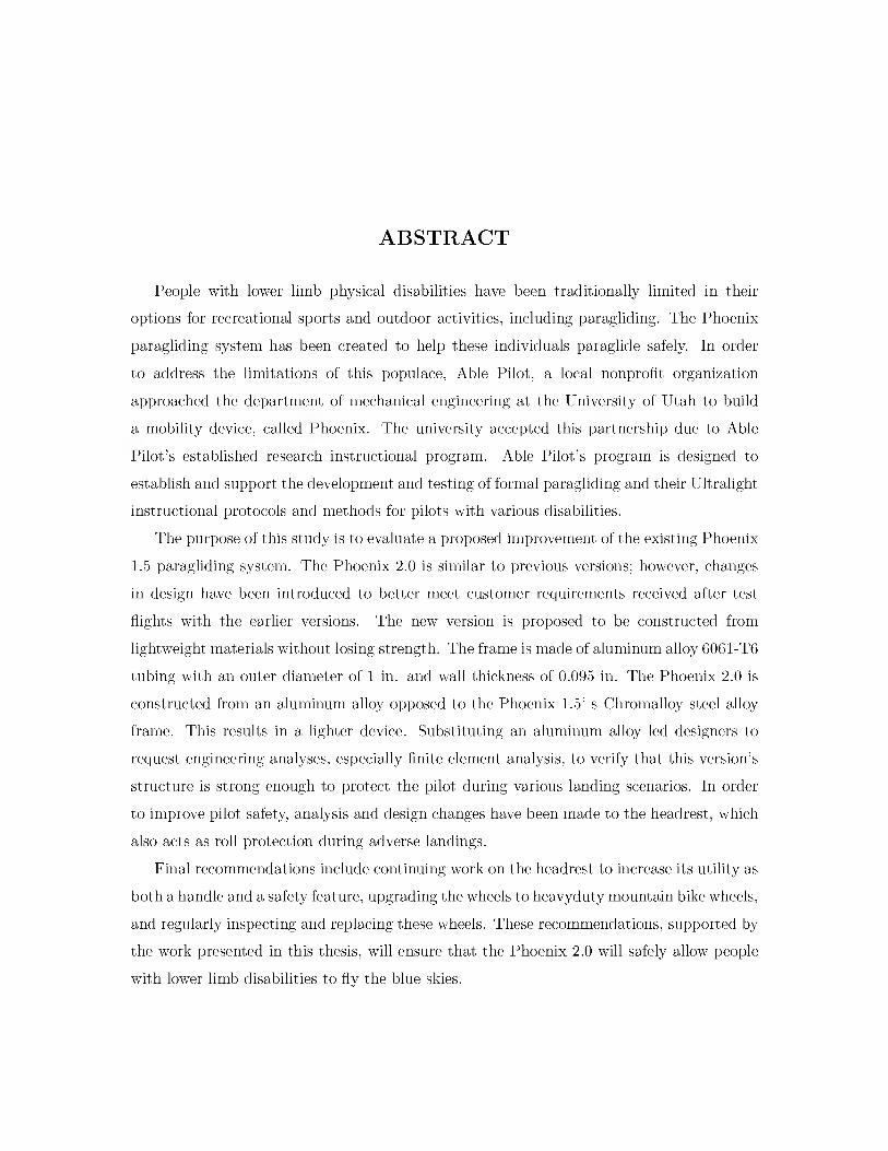
ABSTRACTPeople with lower limb physical disabilities have been traditionally limited in their
options for recreational sports and outdoor activities, including paragliding. The Phoenix paragliding system has been created to help these individuals paraglide safely. In order to address the limitations of this populace, Able Pilot, a local nonprofit organization approached the department of mechanical engineering at the University of Utah to build a mobility device, called Phoenix. The university accepted this partnership due to Able Pilot's established research instructional program. Able Pilot's program is designed to establish and support the development and testing of formal paragliding and their Ultralight instructional protocols and methods for pilots with various disabilities.
The purpose of this study is to evaluate a proposed improvement of the existing Phoenix1.5 paragliding system. The Phoenix 2.0 is similar to previous versions; however, changes in design have been introduced to better meet customer requirements received after test flights with the earlier versions. The new version is proposed to be constructed from lightweight materials without losing strength. The frame is made of aluminum alloy 6061-T6 tubing with an outer diameter of 1 in. and wall thickness of 0.095 in. The Phoenix 2.0 is constructed from an aluminum alloy opposed to the Phoenix 1.5’ s Chromalloy steel alloy frame. This results in a lighter device. Substituting an aluminum alloy led designers to request engineering analyses, especially finite element analysis, to verify that this version’s structure is strong enough to protect the pilot during various landing scenarios. In order to improve pilot safety, analysis and design changes have been made to the headrest, which also acts as roll protection during adverse landings.
Final recommendations include continuing work on the headrest to increase its utility as both a handle and a safety feature, upgrading the wheels to heavyduty mountain bike wheels, and regularly inspecting and replacing these wheels. These recommendations, supported by the work presented in this thesis, will ensure that the Phoenix 2.0 will safely allow people with lower limb disabilities to fly the blue skies.
CONTENTSA B S T R A C T ........................................................................................................................... iii LIST OF F IG U R E S ............................................................................................................ vi LIST OF T A B L E S ................................................................................................................ ix A C K N O W L E D G M E N T S ................................................................................................ x C H A P T E R S 1..... IN T R O D U C T IO N ....................................................................................................... 1
1.1 P arag lid ing ................................................................................................................ 11.2 Paragliding h is to ry ................................................................................................... 11.3 Safety ......................................................................................................................... 21.4 Paragliding for disabled pilots................................................................................. 21.5 Phoenix ....................................................................................................................... 4
1.5.1 Phoenix 1 .0 ....................................................................................................... 41.5.2 Phoenix 1.5 ....................................................................................................... 51.5.3 Phoenix 2 .0 ....................................................................................................... 7
2. SY STEM D E SIG N ..................................................................................................... 82.1 Frame ......................................................................................................................... 82.2 Footrest....................................................................................................................... 11
2.2.1 First ite ra tio n ................................................................................................... 112.2.2 Second iteration .............................................................................................. 112.2.3 Third iteration ................................................................................................ 14
2.3 Headrest ..................................................................................................................... 162.3.1 First ite ra tio n ................................................................................................... 162.3.2 Second iteration .............................................................................................. 16
2.4 Frame weight .............................................................................................................. 182.5 Design change summary .......................................................................................... 18
3. SY STEM E V A L U A T IO N .......................................................................................... 233.1 System engineering tool .......................................................................................... 23
3.1.1 Requirements ................................................................................................... 233.1.2 Essential activities............................................................................................ 243.1.3 Technical requirements dictionary ............................................................... 243.1.4 Functional decomposition diagram ............................................................... 243.1.5 Trade study ....................................................................................................... 27
3.2 Failure mode effect analysis ................................................................................... 273.2.1 Risk priority number........................................................................................ 28
3.2.2 Weighted s c o re ................................................................................................. 283.3 Finite element analy sis ............................................................................................ 343.4 Push rod member stress calculation Phoenix 2 .0 ............................................... 363.5 Calculation of the quick release............................................................................... 36
4. RESULTS AND D IS C U S S IO N ............................................................................... 384.1 Roll envelope for Phoenix 2.0 ................................................................................. 384.2 FEA results ................................................................................................................ 40
4.2.1 Frame ................................................................................................................ 404.2.2 Headrest ............................................................................................................ 50
5. R E C O M M E N D A T IO N S ............................................................................................ 625.1 Frame ......................................................................................................................... 625.2 Headrest ..................................................................................................................... 62
6. C O N C L U S IO N .............................................................................................................. 66 R E F E R E N C E S ..................................................................................................................... 68
v

LIST OF FIGURES1.1 Disabled passenger with his pilot behind ................................................................... 31.2 Phoenix 1 .0 ....................................................................................................................... 41.3 Phoenix 1.0 fram e ............................................................................................................ 51.4 Phoenix 1 .5 ....................................................................................................................... 62.1 Frame with wheels, side v ie w ....................................................................................... 82.2 Frame with suspension a rm s .......................................................................................... 92.3 Frame with wheels, top view ....................................................................................... 102.4 First iteration footrest with independent base for each fo o t.................................... 122.5 First iteration footrest with protection b a r s ............................................................... 122.6 Second iteration footrest, side view............................................................................... 132.7 Second iteration footrest, isometric view...................................................................... 132.8 Third footrest iteration, side view................................................................................. 142.9 Third footrest iteration, isometric view........................................................................ 15
2.10 Third footrest iteration, alternative v ie w ................................................................... 152.11 Phoenix 1.0 headrest....................................................................................................... 162.12 First iteration headrest................................................................................................... 172.13 Second iteration headrest .............................................................................................. 172.14 Phoenix 2.0 assembly showing each p a r t ...................................................................... 212.15 Phoenix 2.0 ....................................................................................................................... 223.1 Functional decomposition d iag ram ............................................................................... 273.2 Severity guideline ............................................................................................................ 293.3 Occurrence guidelines (probability)............................................................................... 293.4 Detection guidelines ....................................................................................................... 303.5 Headrest stress m o d e l..................................................................................................... 343.6 The deflection and torsional deflection at the supported e n d .................................. 354.1 Roll envelop diagram ....................................................................................................... 394.2 Phoenix 2.0 headrest....................................................................................................... 394.3 Calculated impact forces versus landing velocity ...................................................... 41

4.4 Calculated stresses while applying the load over all four wheels............................. ... 424.5 Calculated deflections while applying the load over all four w h ee ls ...................... ... 424.6 Calculated stresses while applying the total load on the rear wheels o n ly ........... ... 434.7 Calculated deflections while applying the total load on the rear wheels only . . . . 444.8 Calculated stresses while applying the total load on the front wheels only ............ 454.9 Calculated deflection while applying the total load on the front wheels only . . . . 45
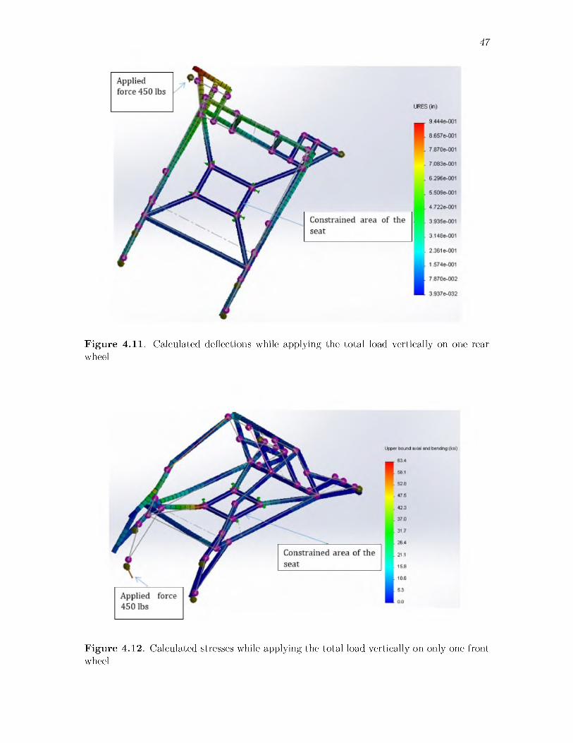
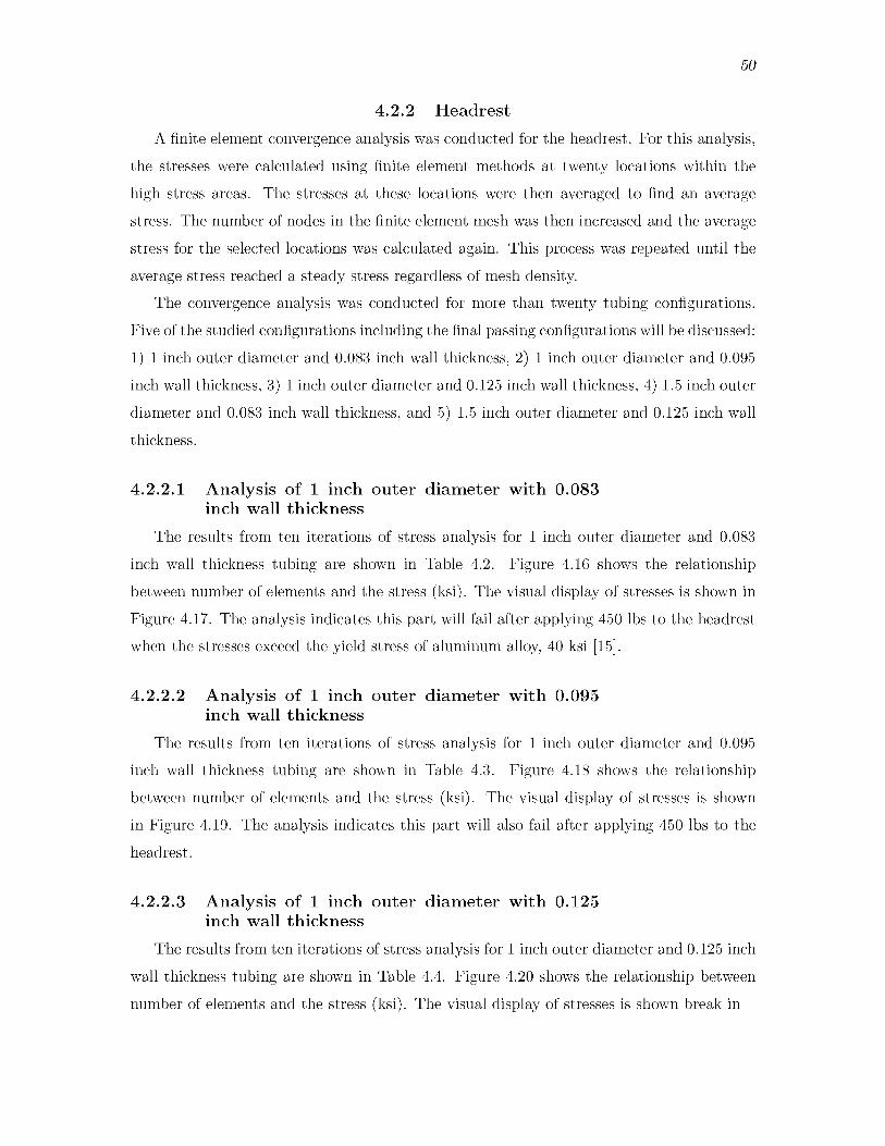
4.10 Calculated stresses while applying the total load vertically on one rear wheel . . . 464.11 Calculated deflections while applying the total load vertically on one rear wheel 474.12 Calculated stresses while applying the total load vertically on only one front wheel 474.13 Calculated deflections while applying the total load vertically on only one front
wheel .................................................................................................................................. 484.14 Calculated stresses while applying the total load in 45 degree direction on only
one of the rear wheels ..................................................................................................... 494.15 Calculated deflections while applying the total load in 45 degree direction on
only one of the rear wheels ............................................................................................ 494.16 Stress vs. number of elements in the finite element model for 1 inch outer
diameter and 0.083 inch wall thickness........................................................................ 514.17 The stresses in 1 in outer diameter and 0.083 inch wall thickness headrest on
Abaqus FEA software ..................................................................................................... 524.18 Stress vs. number of elements in the finite element model for 1 inch outer
diameter and 0.095 inch wall thickness........................................................................ 534.19 The stresses in 1 in outer diameter and 0.095 inch wall thickness headrest on
Abaqus FEA software ..................................................................................................... 534.20 Stress vs. number of elements in the finite element model for 1 inch outer
diameter and 0.125 inch wall thickness........................................................................ 544.21 The stresses in 1 in outer diameter and 0.125 inch wall thickness headrest on
Abaqus FEA software ..................................................................................................... 554.22 Stress vs. number of elements in the finite element model for 1.125 inch outer
diameter and 0.083 inch wall thickness........................................................................ 564.23 The stresses in 1.125 in outer diameter and 0.083 inch wall thickness headrest
on Abaqus FEA software ................................................................................................. 574.24 Stress vs. number of elements in the finite element model for 1.5 inch outer
diameter and 0.125 inch wall thickness ........................................................................ 584.25 The stresses in 1.5 in outer diameter and 0.125 inch wall thickness headrest on
Abaqus FEA software ..................................................................................................... 584.26 The stresses in 1 inch outer diameter and 0.095 inch wall thickness headrest
using Solidworks .............................................................................................................. 604.27 The stresses in 1.5 in outer diameter and 0.125 in wall thickness of headrest
using Solidworks software .............................................................................................. 61vii
5.1 Frame and swing suspension arms assembly ..................................................................635.2 Headrest second version ....................................................................................................645.3 Roll envelope dimensions to be recommended................................................................645.4 The maximum stress (ksi) and the weight of head rest in p o u n d s ............................65
viii

LIST OF TABLES2.1 Weight in lbs of head rest for 1 inch outer diameter tubing and varying wall
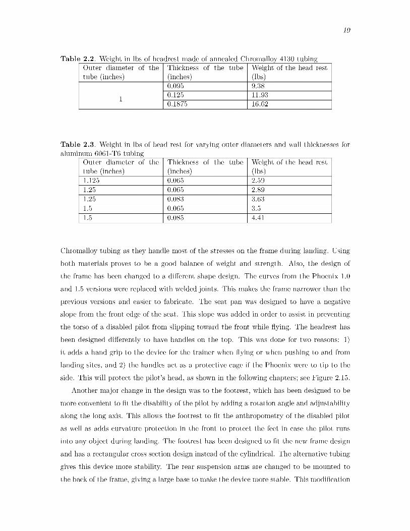
thicknesses for aluminum 6061-T6....................................................................................182.2 Weight in lbs of headrest made of annealed Chromalloy 4130 tub ing .................... ...192.3 Weight in lbs of head rest for varying outer diameters and wall thicknesses for
aluminum 6061-T6 tubing .............................................................................................. 192.4 Phoenix items and the total weight in lbs for each item ..............................................203.1 Customer defined priorities............................................................................................ ...243.2 Phoenix technical requirements..................................................................................... ...253.3 Trade s tu d y ....................................................................................................................... ...283.4 Failure mode effect analysis (F M E A ).......................................................................... ...313.5 Stress calculations...............................................................................................................364.1 Calculated impact force table ........................................................................................ 414.2 Calculated average stress in aluminum headrest with increasing number of ele
ments for 1 inch outer diameter and 0.083 inch wall thickness tubing.................... ...514.3 Calculated average stress in aluminum headrest with increasing number of ele
ments for 1 inch outer diameter and 0.095 inch wall thickness tubing.................... ...524.4 Calculated average stress in aluminum headrest with increasing number of ele
ments for 1 inch outer diameter and 0.125 inch wall thickness tubing.................... ...544.5 Calculated average stress in aluminum headrest with increasing number of ele
ments for 1.125 inch outer diameter and 0.083 inch wall thickness tubing................564.6 Calculated average stress in aluminum headrest with increasing number of ele
ments for 1.5 inch outer diameter and 0.125 inch wall thickness tubing....................575.1 Outer diameter and wall thickness with maximum stress and their weights in
pound.................................................................................................................................. ...65

ACKNOWLEDGMENTSI am grateful for the assistance that many people have given to me during my research.I am especially indebted to my thesis chair, Mechanical Engineering Department advisor
Dr. Donald Bloswick, for his support and guidance while I pursued my graduate studies.I would like to extend my appreciation to my other committee members, Dr. Bruce
Gale of the Mechanical Engineering Department for the time reviewing this thesis and Dr. Andrew Merryweather of the Mechanical Engineering Department for the assistance and the advice that made my research the way it is.
The institute of occupational health and safety is greatly acknowledged for funding this research as well as my graduated studies.
I would like to recognize the students in the ergonomic and safety program for their technical support and friendship, especially Seth Paul and Travis Steele.
I would also like to express my appreciation to Shawn Evans for his help with Abaqus analysis software.

CHAPTER 1INTRODUCTION
1.1 ParaglidingParagliding is an outdoor recreational activity and competitive sport in which a pilot
flies/glides. Flight is accomplished by sitting in a harness suspended below a hollow fabric wing. Air enters vents in the front of the wing to fill the wings. Aerodynamic forces of the air flowing over the wing surface and the thrust force caused by the air inside the wing helps to lift the paraglider. Despite the fact that there is no engine attached to a paraglider, flights can last hours and cover many miles. Normal paragliding systems are portable as all the necessary equipment packs into a rucksack and can be transported on the pilot's back or in vehicles [1]. Powered paragliding is the flying of paragliders by using a small engine attached to the paragliding equipment. Paragliding is available in both winter and summer in mountainous regions. There are many schools and institutes that offer courses to train paragliding pilots. There are also many factories that manufacture and repair paragliding equipment [2].
1.2 Paragliding historyParagliding first began during World War I [3]. These early attempts usually used
parachutes. Some brave navy sailors were also recruited to be towed by parachute behind submarines to explore the Atlantic waters [3]. In 1950, the practice of using a vent in the back of the chute to help directional control and enhance the gliding was invented [3]. In 1958, two inventors, Francis and Gertrude Rogallo, are credited for inventing the Rogallo Wing [3]. The Rogallo Wing is a flexible type of airfoil also called a flexible wing. NASA considered this wing as an alternative recovery system for the Gemini space capsule [3]. By1963, David Barish, while working for NASA, performed his first flight in New York [3]. In1964, Domina Jalbert invented the shape of the Ram Air canopy [3]. The Ram Air canopy has an open leading edge and sewn trailing edges that act as fabric one-way valves.
The incoming air fills the sail to give it a wing shape [3]. In the early 1970s, the British
2
Association of Parascending used Ram Air canopies and paracommanders towed behind a vehicle and then released [3]. In 1978, French parachutists, Jean Claude, Andre Bohn, and Gerard Bosson, introduced running and launching from a slope in Mieussy, France. This site is now considered the Mecca of paragliding [3]. The following year, Gerard Bosson participated in hang gliding championships [3]. In the 1990s, the X38 was developed by NASA and was tested in January of 2000 by releasing the X38 from a B52 jet over the Mojave Desert. The vertical speed of the X38 reached 60 miles per hour. The parafoil expanded and helped to reduce the vertical speed to 8 miles per hour for a soft touchdown [3]. In January of 2000, the largest parafoil ever constructed was tested over the Mojave Desert.
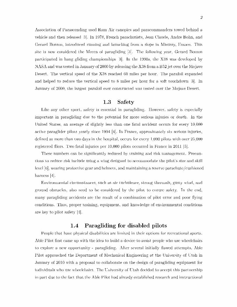
1.3 SafetyLike any other sport, safety is essential in paragliding. However, safety is especially
important in paragliding due to the potential for more serious injuries or death. In the United States, an average of slightly less than one fatal accident occurs for every 10,000 active paraglider pilots yearly since 1994 [4]. In France, approximately six serious injuries, defined as more than two days in the hospital, occurs for every 1,000 pilots with over 25,000 registered fliers. Two fatal injuries per 10,000 pilots occurred in France in 2011 [5].
These numbers can be significantly reduced by training and risk management. Precautions to reduce risk include using a wing designed to accommodate the pilot’s size and skill level [6], wearing protective gear and helmets, and maintaining a reserve parachute/cushioned harness [4].
Environmental circumstances, such as air turbulence, strong thermals, gusty wind, and ground obstacles, also need to be considered by the pilot to ensure safety. In the end, many paragliding accidents are the result of a combination of pilot error and poor flying conditions. Thus, proper training, equipment, and knowledge of environmental conditions are key to pilot safety [4].
1.4 Paragliding for disabled pilotsPeople that have physical disabilities are limited in their options for recreational sports.
Able Pilot first came up with the idea to build a device to assist people who use wheelchairs to explore a new opportunity - paragliding. After several initially flawed attempts, Able Pilot approached the Department of Mechanical Engineering at the University of Utah in January of 2010 with a proposal to collaborate on the design of paragliding equipment for individuals who use wheelchairs. The University of Utah decided to accept this partnership in part due to the fact that the Able Pilot had already established research and instructional

3
programs for disabled pilots. Able Pilot supports the development and testing of formal paragliding, hang gliding, and ultralight instructional protocols and methods for pilots with various physical disabilities [7].
As a result of the partnership between these two institutes, the Phoenix project was born. This project has resulted in two previous versions of the Phoenix, the Phoenix 1, the Phoenix 1.5, and now the proposed Phoenix 2.0 discussed in this thesis. The Phoenix paragliding system provides access to paragliding or other high altitude sports for people with lower body disabilities, e.g. spinal cord injuries, amputations, or neuromuscular diseases, and allows people with these disabilities to fly with able bodied pilots, shown in Figure 1.1. This program helps these individuals to safely experience the freedom, joys, and sense of accomplishment of free flight that paragliding provides [7]. Taking off and landing are the two most critical and challenging aspects for a disabled paraglider [7]. Once the Phoenix is in the air, it is far less critical if the pilot has lower body disability as controls are all arm actuated. The most critical subsystem of the Phoenix design is the suspension. The suspension on all Phoenix systems is designed to cushion the impact during landing. Several engineering analyses and engineering tools have been applied in during Phoenix development with the end goal of producing a better Phoenix design with each iteration [7].
F ig u re 1.1. Disabled passenger with his pilot behind
4
The first comprehensive test for Phoenix was in Sun Valley, Idaho in the summer of 2011. During this time, five injured military veterans were trained to fly in a solo-tandem pair using the Phoenix 1.0 and Phoenix 1.5 [7]. The next training was in April 2012 in Santa Barbara, California. This training session had three purposes: 1) to test the new device, 2) to fully certify two veterans with disabilities as paraglider pilots, and 3) to get feedback from operators. This feedback was used to enhance the device to better match the needs of these people and their disabilities [7].
1.5 PhoenixThe Phoenix is a lightweight wheelchair structure that assists people with lower limb
disabilities to paraglide. The most critical part of the Phoenix design is the suspension swing-arms. These are designed to cushion the impact of landing [7]. The following sections will discuss the previous iterations of the Phoenix system.
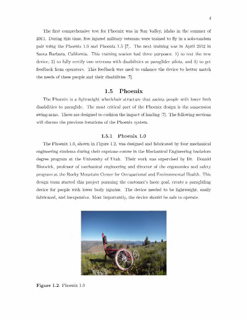
1.5.1 P h o e n ix 1.0The Phoenix 1.0, shown in Figure 1.2, was designed and fabricated by four mechanical
engineering students during their capstone course in the Mechanical Engineering bachelors degree program at the University of Utah. Their work was supervised by Dr. Donald Bloswick, professor of mechanical engineering and director of the ergonomics and safety program at the Rocky Mountain Center for Occupational and Environmental Health. This design team started this project pursuing the customer's basic goal, create a paragliding device for people with lower body injuries. The device needed to be lightweight, easily fabricated, and inexpensive. Most importantly, the device should be safe to operate.
F ig u re 1.2. Phoenix 1.0
5
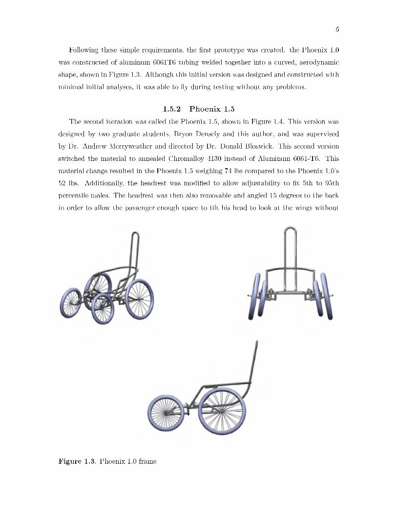
Following these simple requirements, the first prototype was created. the Phoenix 1.0 was constructed of aluminum 6061T6 tubing welded together into a curved, aerodynamic shape, shown in Figure 1.3. Although this initial version was designed and constructed with minimal initial analyses, it was able to fly during testing without any problems.
1.5.2 P h o e n ix 1.5The second iteration was called the Phoenix 1.5, shown in Figure 1.4. This version was
designed by two graduate students, Bryon Densely and this author, and was supervised by Dr. Andrew Merryweather and directed by Dr. Donald Bloswick. This second version switched the material to annealed Chromalloy 4130 instead of Aluminum 6061-T6. This material change resulted in the Phoenix 1.5 weighing 74 lbs compared to the Phoenix 1.0’s 52 lbs. Additionally, the headrest was modified to allow adjustability to fit 5th to 95th percentile males. The headrest was then also removable and angled 15 degrees to the back in order to allow the passenger enough space to tilt his head to look at the wings without
F ig u re 1.3. Phoenix 1.0 frame

6
Figure 1.4. Phoenix 1.5
7
the back of the helmet contacting the head rest. The foot rest was also tilted in this second version to be more comfortable. This design incorporated a quick release on the wheels. This quick release had a 12 mm diameter to fit the bearing inside the wheels. This quick release allowed easy assembly and disassembly for transport. The Phoenix 1.5 also had a reduction in overall number of pieces and welded joints to streamline fabrication.
1.5 .3 P h o e n ix 2.0After receiving feedback about the Phoenix 1.5, the Phoenix 2.0 design was proposed.
The remainder of this document will discuss the analysis and results of the proposed changes. The main design changes include:
• reintegration of use of aluminum 6061-T6 for some portions of the frame,
• redesign of the headrest, and• redesign of the footrest.
The following manuscript is organized into sections.
• Chapter 2: Phoenix 2.0 system design• Chapter 3: Phoenix 2.0 system evaluation• Chapter 4: Summary of results and discussion of the Phoenix 2.0
• Chapter 5: Recommendations

CHAPTER 2SYSTEM DESIGN
2.1 FrameThere are multiple proposed changes in the Phoenix 2.0 frame design. Changes were
made to the frame shape following feedback from the pilots who flew previous versions of the Phoenix. Lower body disabilities make it difficult to keep the body stable inside the seat since the lower body tends to slip to the front during flight. In order to prevent this shift, the seat support for the new frame design has been angled to the back, as shown in Figure 2.1.
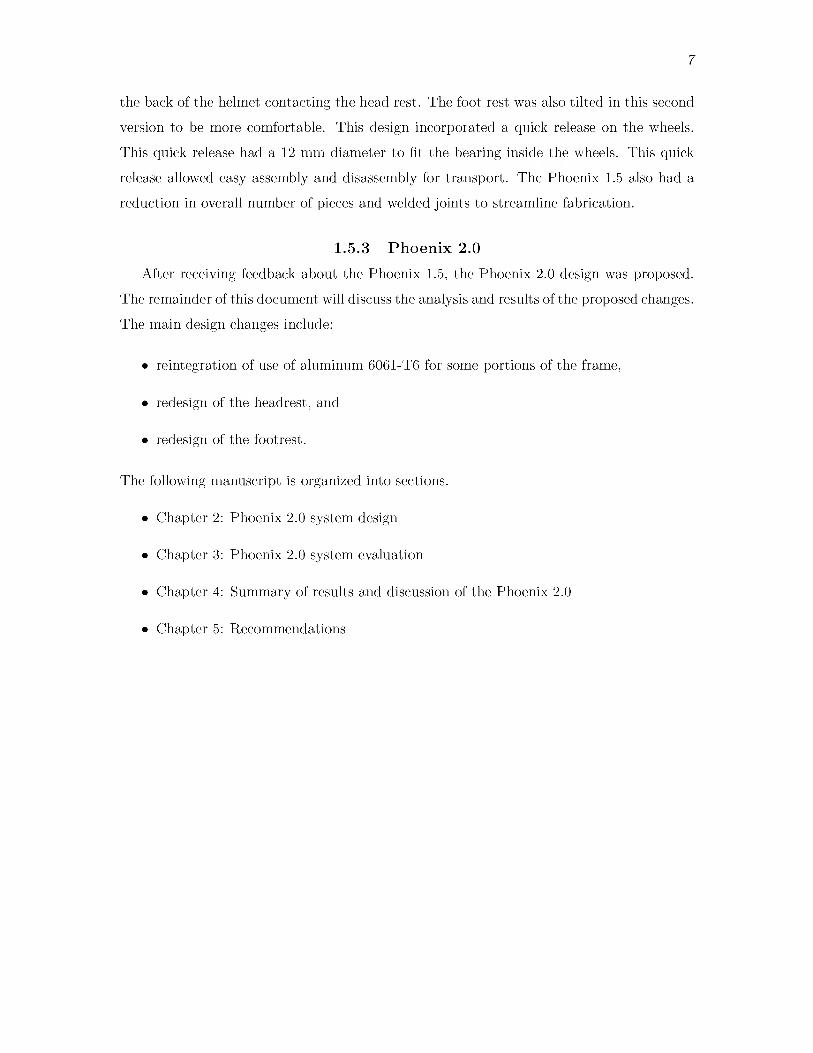
The shape of the frame in the Phoenix 2.0 has fewer curves and more welded angular joints than in previous versions, as shown in Figure 2.2. This results in a less aesthetic shape but will make it easier to fabricate and thus decrease fabrication costs.
The location of the rear swing arms was also moved, shown in Figure 2.3. This relocation was chosen as most of the load stresses will be on the rear wheels. The proposed design better resists the impact of the load using the same shock absorption system used in the
\
Figure 2.1. Frame with wheels, side view
9
Figure 2.2. Frame with suspension arms

10
Figure 2.3. Frame with wheels, top view

11
Phoenix 1.0 and 1.5.Finally, the material used in the frame is aluminum alloy 6061-T6. This material change
results in a frame weight of 48.98 lbs. This material was also used in the Phoenix 1.0. The switch to aluminum decreases the total weight of the device and makes it lighter than the Phoenix 1.5, which was 74 lbs.
2.2 FootrestThe foot support rest was designed specifically for people that have spinal cord injuries
or lower body disabilities. The nature of their injury means that the target users cannot control their feet, so the foot supports must both contain and protect their feet. If the Phoenix were to be positioned on a steep slope during take-off or landing, the lack of lower limb control means there is a possibility the pilot's legs may shift, potentially throwing the entire device off balance. All of these aspects were considered in the various iterations leading up to the final design, as shown in the following figures.
2 .2 .1 F ir s t i te ra t io nThis design was the same as the footrest on the Phoenix 1.0 and 1.5 with a few minor
differences. The main bar was previously cylindrical but has been changed to a rectangular cross-section. This prevents the footrest assembly from rotating about the long support axis, which caused unnecessary shearing stress on the pin used to lock the length adjustment in place. The second difference was to design a separate base for each foot. Having each foot attach independently to the T-bar allows each foot to be tilted independently, shown in Figure 2.4. This may be important for some pilots who may have different needs for each foot, according to their disability. Finally, adding protection bars to the footrest, shown in Figure 2.5, helps to protect the feet from any object that might be in front of the Phoenix during landing.
2 .2 .2 S econd i te ra t io nAfter receiving feedback from the design team and the pilots, the second iteration
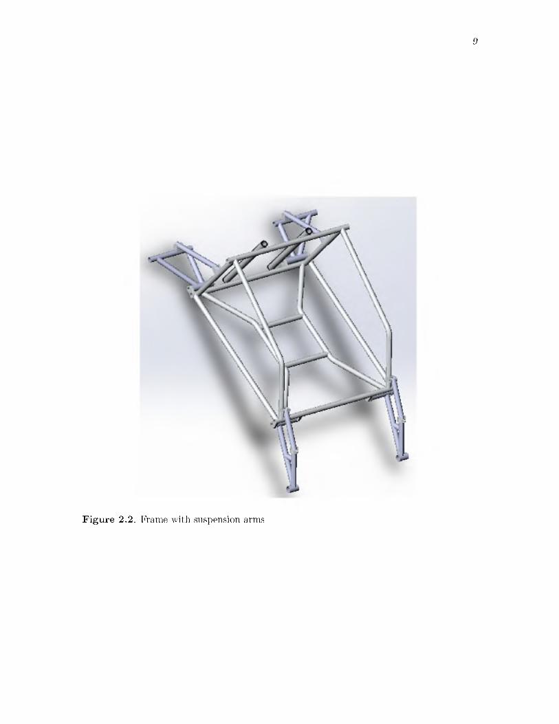
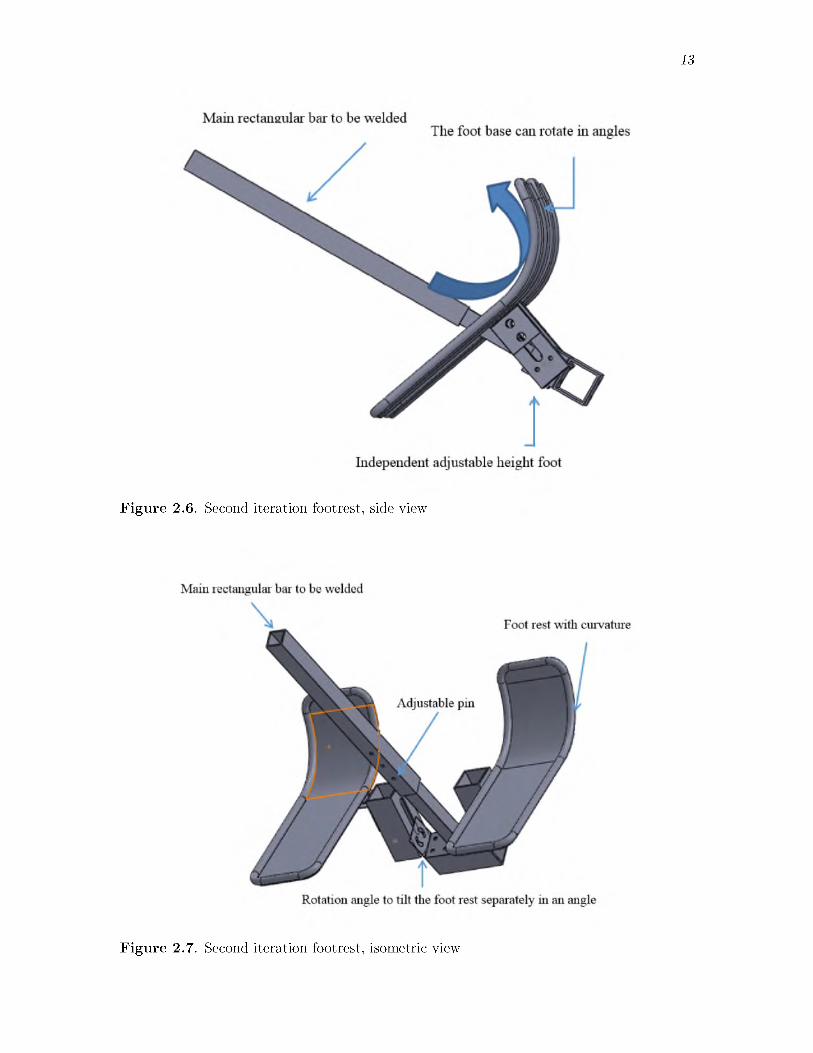
incorporated many design changes. Specifically, adding more degrees of freedom allowed greater movement of the feet and greater adjustability. These modifications enable the design to handle a wider range of disabilities. Adding an adjustable bar to each footplate, as shown in Figure 2.6, allows the footrest to accommodate those with one leg shorter than the other. In order to compensate for the potentially uncomfortable angle of the bindings, an adjustable rotation plate was added, shown in Figure 2.7. This again allows each foot

12
Protection
Figure 2.4. First iteration footrest with independent base for each foot
F ig u re 2.5. First iteration footrest with protection bars
13
Figure 2.6. Second iteration footrest, side view
F ig u re 2.7. Second iteration footrest, isometric view
14
to tilt independently. Finally, the protection bar was updated to a curved tube similar to that found on a ski, also shown in Figure 2.7.
Many different configurations were considered for this design, especially regarding the rotation angle. However, the second iteration was driven by the design goals of ease of fabrication, low weight, low cost, and low fabrication time. Unfortunately, this design was not optimal with respect to simplicity of fabrication since it has many custom parts. This complexity prompted a third iteration.
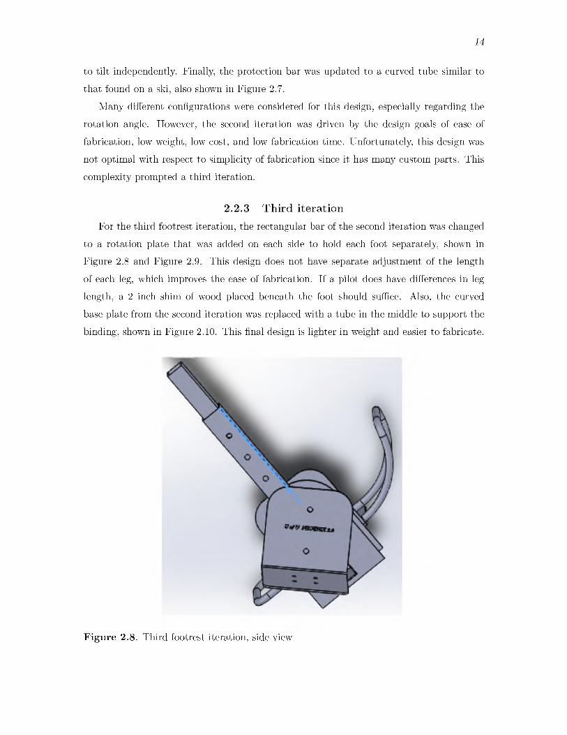
2 .2 .3 T h ird i te ra t io nFor the third footrest iteration, the rectangular bar of the second iteration was changed
to a rotation plate that was added on each side to hold each foot separately, shown in Figure 2.8 and Figure 2.9. This design does not have separate adjustment of the length of each leg, which improves the ease of fabrication. If a pilot does have differences in leg length, a 2 inch shim of wood placed beneath the foot should suffice. Also, the curved base plate from the second iteration was replaced with a tube in the middle to support the binding, shown in Figure 2.10. This final design is lighter in weight and easier to fabricate.
F ig u re 2.8. Third footrest iteration, side view

F ig u re 2.10. Third footrest iteration, alternative view
16
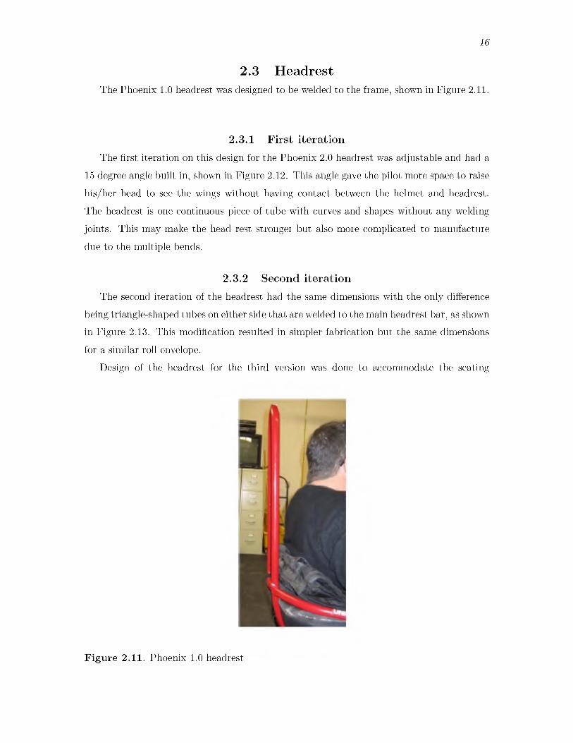
2.3 HeadrestThe Phoenix 1.0 headrest was designed to be welded to the frame, shown in Figure 2.11.
2 .3 .1 F ir s t i te ra t io nThe first iteration on this design for the Phoenix 2.0 headrest was adjustable and had a
15 degree angle built in, shown in Figure 2.12. This angle gave the pilot more space to raise his/her head to see the wings without having contact between the helmet and headrest. The headrest is one continuous piece of tube with curves and shapes without any welding joints. This may make the head rest stronger but also more complicated to manufacture due to the multiple bends.
2 .3 .2 S econd i te ra t io nThe second iteration of the headrest had the same dimensions with the only difference
being triangle-shaped tubes on either side that are welded to the main headrest bar, as shown in Figure 2.13. This modification resulted in simpler fabrication but the same dimensions for a similar roll envelope.
Design of the headrest for the third version was done to accommodate the seating
F ig u re 2.11. Phoenix 1.0 headrest

17
F ig u re 2.13. Second iteration headrest

18
dimensions of up to a 95th percentile male. Based on this, the maximum space needed from the bottom of the seat to the head of the pilot is 38.3 inches [8]. With 6 inches of adjustment built in, the current headrest will cover almost every pilot’s height. For shorter pilots, there will be more protection. The final shape of the head rest was designed to protect the pilot in case the Phoenix 2.0 tips over to the front or side. The roll envelope calculations are show in the following chapter.
2.4 Frame weightWeight is of crucial importance in the design of the Phoenix. Many outer diameters and
wall thicknesses have been tested to compare their weights and to see how the total weight of the main assembly is affected. The effect of wall thickness on headrest weight for 1 inch outer diameter aluminum 6061-T6 tubing is shown in Table 2.1. The calculated stresses on the 1 inch outer diameter aluminum 6061-T6 tubing was found to be above the yield stress, indicating the tubing would fail under these conditions. Annealed Chromalloy was then considered. The effect of wall thickness on weight for 1 inch outer diameter annealed Chromalloy is shown in Table 2.2.
The calculated stresses on the 1 inch outer diameter annealed Chromalloy tubing was also found to be above the yield stress, indicating the annealed Chromalloy headrest was much heavier but with negligible strength benefit. Larger outer diameters were then considered to meet the yield stress with the aluminum alloy. The effect of outer diameter and wall thickness on weight for aluminum 6061-T6 is shown in Table 2.3.
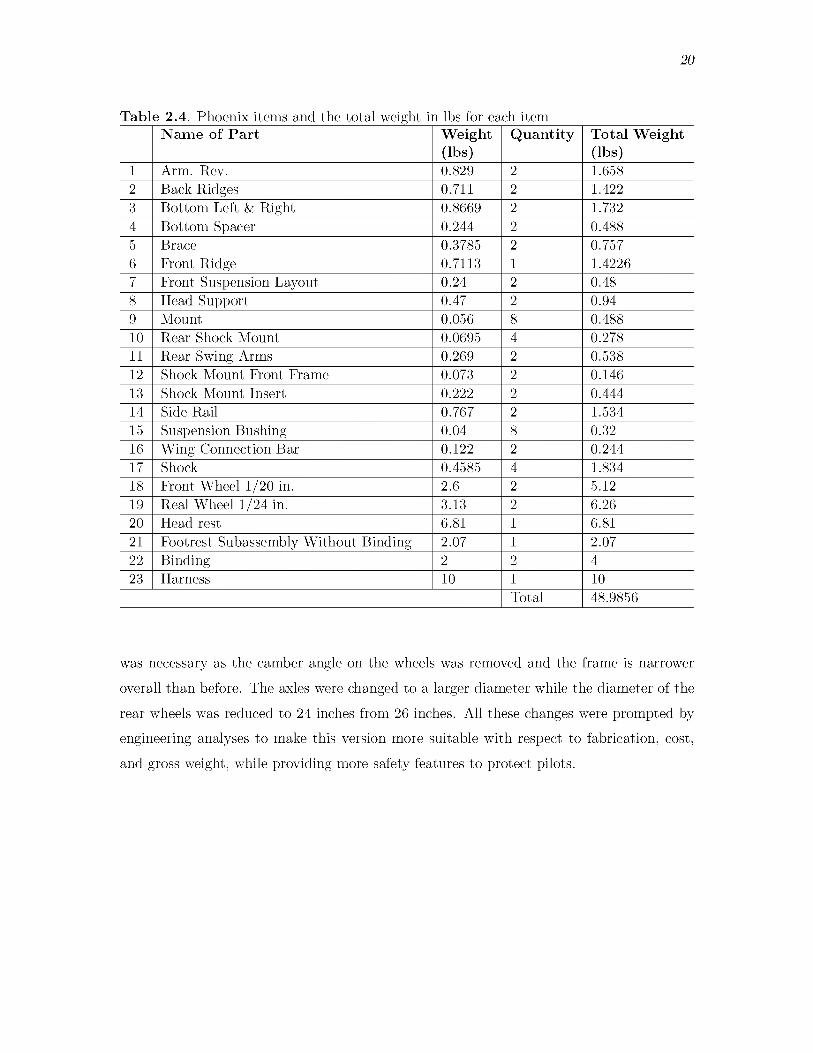
The weight and quantity of Phoenix 2.0 components and total calculated weight are displayed in Table 2.4. The part locations listed in Table 2.4 are illustrated in Figure 2.14.
2.5 Design change summaryIn summary, the material of the Phoenix 2.0 frame has been changed back to Aluminum
6061-T6 tubing. However, the suspension arms are still constructed of 4130 annealed
Table 2.1. Weight in lbs of head rest for 1 inch outer diameter tubing and varying wall thicknesses for aluminum 6061-T6Outer diameter of the
tube (inches)Thickness of the tube (inches)
Weight of the head rest (lbs)
10.095 3.230.125 4.100.1875 5.720.250 7.04
19
Table 2.2. Weight in lbs of headrest made of annealed C iromalloy 4130 tubingOuter diameter of the tube (inches)
Thickness of the tube (inches)
Weight of the head rest (lbs)
0.095 9.380.125 11.930.1875 16.621
Table 2.3. Weight in lbs of head rest for varying outer diameters and wall thicknesses for aluminum 6061-T6 tubing
Outer diameter of the tube (inches)
Thickness of the tube (inches)
Weight of the head rest (lbs)
1.125 0.065 2.591.25 0.065 2.891.25 0.083 3.631.5 0.065 3.51.5 0.085 4.41
Chromalloy tubing as they handle most of the stresses on the frame during landing. Using both materials proves to be a good balance of weight and strength. Also, the design of the frame has been changed to a different shape design. The curves from the Phoenix 1.0 and 1.5 versions were replaced with welded joints. This makes the frame narrower than the previous versions and easier to fabricate. The seat pan was designed to have a negative slope from the front edge of the seat. This slope was added in order to assist in preventing the torso of a disabled pilot from slipping toward the front while flying. The headrest has been designed differently to have handles on the top. This was done for two reasons: 1) it adds a hand grip to the device for the trainer when flying or when pushing to and from landing sites, and 2) the handles act as a protective cage if the Phoenix were to tip to the side. This will protect the pilot's head, as shown in the following chapters; see Figure 2.15.
Another major change in the design was to the footrest, which has been designed to be more convenient to fit the disability of the pilot by adding a rotation angle and adjustability along the long axis. This allows the footrest to fit the anthropometry of the disabled pilot as well as adds curvature protection in the front to protect the feet in case the pilot runs into any object during landing. The footrest has been designed to fit the new frame design and has a rectangular cross section design instead of the cylindrical. The alternative tubing gives this device more stability. The rear suspension arms are changed to be mounted to the back of the frame, giving a large base to make the device more stable. This modification
20
Table 2.4. Phoenix items and the total weight in lbs for each itemN am e of P a r t W eight
(lbs)Q uan tity Total W eight
(lbs)1 Arm. Rev. 0.829 2 1.6582 Back Ridges 0.711 2 1.4223 Bottom Left & Right 0.8669 2 1.7324 Bottom Spacer 0.244 2 0.4885 Brace 0.3785 2 0.7576 Front Ridge 0.7113 1 1.42267 Front Suspension Layout 0.24 2 0.488 Head Support 0.47 2 0.949 Mount 0.056 8 0.48810 Rear Shock Mount 0.0695 4 0.27811 Rear Swing Arms 0.269 2 0.53812 Shock Mount Front Frame 0.073 2 0.14613 Shock Mount Insert 0.222 2 0.44414 Side Rail 0.767 2 1.53415 Suspension Bushing 0.04 8 0.3216 Wing Connection Bar 0.122 2 0.24417 Shock 0.4585 4 1.83418 Front Wheel 1/20 in. 2.6 2 5.1219 Real Wheel 1/24 in. 3.13 2 6.2620 Head rest 6.81 1 6.8121 Footrest Subassembly Without Binding 2.07 1 2.0722 Binding 2 2 423 Harness 10 1 10
Total 48.9856
was necessary as the camber angle on the wheels was removed and the frame is narrower overall than before. The axles were changed to a larger diameter while the diameter of the rear wheels was reduced to 24 inches from 26 inches. All these changes were prompted by engineering analyses to make this version more suitable with respect to fabrication, cost, and gross weight, while providing more safety features to protect pilots.

21
Figure 2.14. Phoenix 2.0 assembly showing each part

22
Figure 2.15. Phoenix 2.0
CHAPTER 3SYSTEM EVALUATION
3.1 System engineering toolSystem engineering tools focus on how to design and manage the project over the
expected lifetime by using reliability, evaluation, and requirement management [9]. System engineering focuses on the whole system while considering subsystems, both from the outside and with interactions with other subsystems and the environment. System engineering deals not only with the internal design but with external factors as well [10].
Use of this tool ensures consideration of the big picture and must ensure that the Phoenix device meets its requirements throughout the entire system life cycle. Including system engineering early in the design phase increases the probability of success, reduces risk, and reduces total life cycle cost [10]. The long-term goal of using this tool in this study is to enhance the project and to benefit future iterations of the Phoenix design.
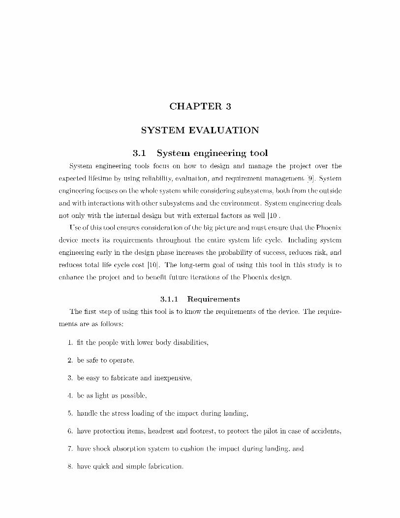
3 .1 .1 R e q u ire m e n tsThe first step of using this tool is to know the requirements of the device. The require
ments are as follows:
1. fit the people with lower body disabilities,2. be safe to operate,3. be easy to fabricate and inexpensive,4. be as light as possible,5. handle the stress loading of the impact during landing,6. have protection items, headrest and footrest, to protect the pilot in case of accidents,7. have shock absorption system to cushion the impact during landing, and8. have quick and simple fabrication.

24
3.1 .2 E sse n tia l a c tiv itie sSix essential activities transform the customer need into a total system solution [11].
These activities are as follows:1. Elicitation - listen to the customer’s needs and transform these needs into technical
requirements: in this case, Able Pilot’s request for a device that can fit people with disabilities, enabling them to paraglide.
2. Collaboration - work together with the customer and project members to analyze data, engineer products, and determine the effect of the environment on the system.
3. Analysis - investigate trade-off assessments of the system.4. Architecting - invent and define the overall system, and investigate the relationship
of the components.5. Conceptualizing - visualize the final working system.6. Modeling - create the prototype to define the relationship between the components in
the system and to interpret the previous steps into a real model.The scores of each factor are shown in Table 3.1.
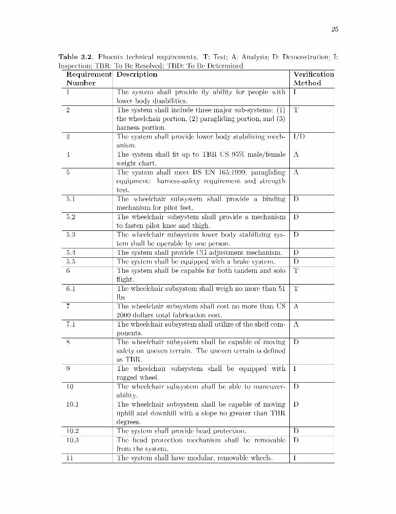
3 .1 .3 T ech n ica l re q u ire m e n ts d ic t io n a ryThe technical requirements translations are shown in Table 3.2 [9].
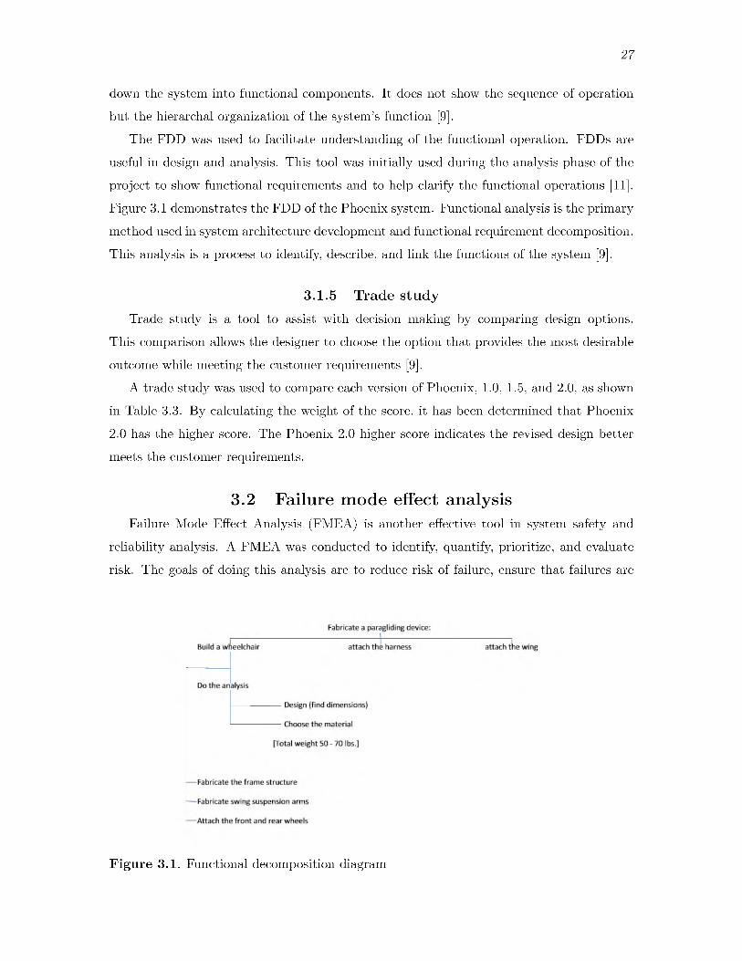
3 .1 .4 F u n c tio n a l d e c o m p o s itio n d ia g ra mA functional decomposition diagram (FDD) is a process of considering systems at high
levels and then dividing entities into smaller related parts. FDD is an analysis tool to break
Table 3.1. Customer directed priorities. A score of 50 is high weight, a score of 10 is low weight. _________________________________________________________
Score P ro p e r ty factors50 Safety10 Cost40 Reliability20 ScheduleUnscored desires
Ease of shipment (assembly, quick release)Fabricate the first model as quickly as safely possible
25
Table 3.2. Phoenix technical requirements. T: Test; A: Analysis; D: Demonstration; I: Inspection; TBR: To Be Resolved; TBD: To Be Determined__________________________
R equ irem en tN um b er
D escrip tion V erificationM ethod
1 The system shall provide fly ability for people with lower body disabilities.
I2 The system shall include three major sub-systems: (1)
the wheelchair portion, (2) paragliding portion, and (3) harness portion.
T
3 The system shall provide lower body stabilizing mechanism.
I/D4 The system shall fit up to TBR US 95% male/female
weight chart.A
5 The system shall meet BS EN 165:1999, paragliding equipment: harness-safety requirement and strength test.
A
5.1 The wheelchair subsystem shall provide a binding mechanism for pilot feet.
D5.2 The wheelchair subsystem shall provide a mechanism
to fasten pilot knee and thigh.D
5.3 The wheelchair subsystem lower body stabilizing system shall be operable by one person.
D5.4 The system shall provide CG adjustment mechanism. D5.5 The system shall be equipped with a brake system. D6 The system shall be capable for both tandem and solo
flight.T
6.1 The wheelchair subsystem shall weigh no more than 51 lbs
T7 The wheelchair subsystem shall cost no more than US
2000 dollars total fabrication cost.A
7.1 The wheelchair subsystem shall utilize of the shelf components.
A8 The wheelchair subsystem shall be capable of moving
safety on uneven terrain. The uneven terrain is defined as TBR.
D
9 The wheelchair subsystem shall be equipped with rugged wheel.
I
10 The wheelchair subsystem shall be able to maneuverability.
D10.1 The wheelchair subsystem shall be capable of moving
uphill and downhill with a slope no greater than TBR degrees.
D
10.2 The system shall provide head protection. D10.3 The head protection mechanism shall be removable
from the system.D
11 The system shall have modular, removable wheels. I

26
Table 3.2. C ontinuedR equ irem en tN um b er
D escrip tion V erificationM etho d
12 The system shall be capable of landing shock of TBR. T13 The system shall have shock absorption system to pro
tect the pilot when landing.I
14 The system shall be assembled by two people within TBR minutes.
D14.1 The system shall be disassembled by two people within
TBR minutes.D
15 The system without paragliding wind shall be no wider than TBR 34 inches.
T16 The system shall comply with airworthiness require
ment for the corresponding deployment countries.T /A
27
down the system into functional components. It does not show the sequence of operation but the hierarchal organization of the system’s function [9].
The FDD was used to facilitate understanding of the functional operation. FDDs are useful in design and analysis. This tool was initially used during the analysis phase of the project to show functional requirements and to help clarify the functional operations [11]. Figure 3.1 demonstrates the FDD of the Phoenix system. Functional analysis is the primary method used in system architecture development and functional requirement decomposition. This analysis is a process to identify, describe, and link the functions of the system [9].
3 .1 .5 T ra d e s tu d yTrade study is a tool to assist with decision making by comparing design options.
This comparison allows the designer to choose the option that provides the most desirable outcome while meeting the customer requirements [9].
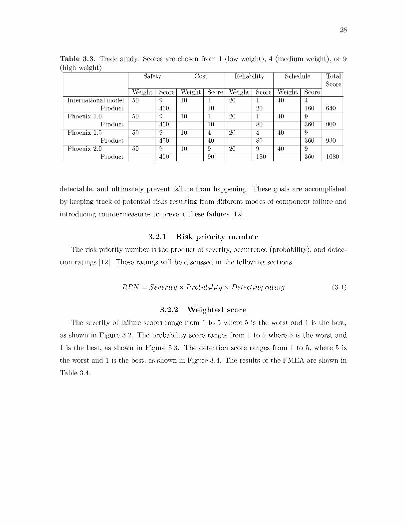
A trade study was used to compare each version of Phoenix, 1.0, 1.5, and 2.0, as shown in Table 3.3. By calculating the weight of the score, it has been determined that Phoenix 2.0 has the higher score. The Phoenix 2.0 higher score indicates the revised design better meets the customer requirements.
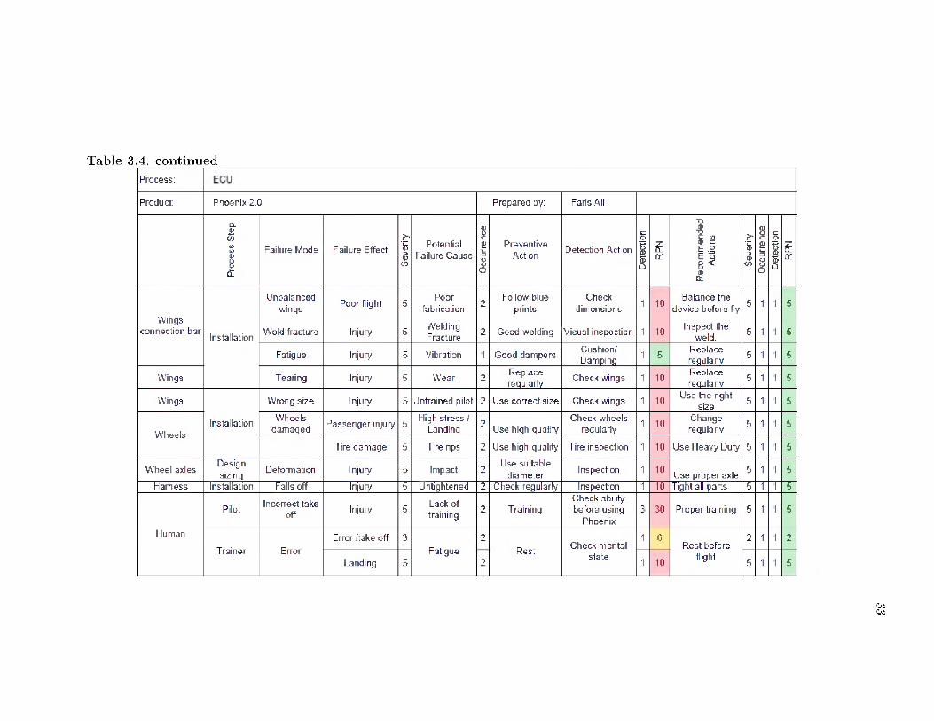
3.2 Failure mode effect analysisFailure Mode Effect Analysis (FMEA) is another effective tool in system safety and
reliability analysis. A FMEA was conducted to identify, quantify, prioritize, and evaluate risk. The goals of doing this analysis are to reduce risk of failure, ensure that failures are
F igure 3.1. Functional decomposition diagram
28
Table 3.3. Trade study. Scores are chosen from 1 (low weight), 4 (medium weight), or 9 (high weight)
Safety Cost Reliability Schedule TotalScore
Weight Score Weight Score Weight Score Weight ScoreInternational model
Product50 9 10 1 20 1 40 4
640450 10 20 160Phoenix 1.0
Product50 9 10 1 20 1 40 9
900450 10 80 360Phoenix 1.5
Product50 9 10 4 20 4 40 9
930450 40 80 360Phoenix 2.0
Product50 9 10 9 20 9 40 9
1080450 90 180 360
detectable, and ultimately prevent failure from happening. These goals are accomplished by keeping track of potential risks resulting from different modes of component failure and introducing countermeasures to prevent these failures [12].
3 .2 .1 R isk p r io r i ty n u m b e rThe risk priority number is the product of severity, occurrence (probability), and detec
tion ratings [12]. These ratings will be discussed in the following sections.
R P N = Severity x Probability x Detecting rating (3.1)
3 .2 .2 W e ig h te d sco reThe severity of failure scores range from 1 to 5 where 5 is the worst and 1 is the best,
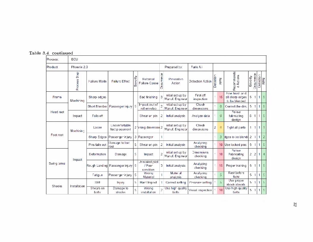
as shown in Figure 3.2. The probability score ranges from 1 to 5 where 5 is the worst and 1 is the best, as shown in Figure 3.3. The detection score ranges from 1 to 5, where 5 is the worst and 1 is the best, as shown in Figure 3.4. The results of the FMEA are shown in Table 3.4.

29
Score
5 Bad Hazardous without warning Potential injury4 High Cause extreme malfunctioning3 Moderate Result in partial malfunctioning2 \ t Low Cause a loss of performance1 Good None W ill not affect the performance
Figure 3.2. Severity guideline
Score 5
4
3
21
Bad
vGood
Very frequent failure
Highly frequent failure Moderately frequent failure Infrequent failure Remote failure
Figure 3.3. Occurrence guidelines (probability)

30
Score
5 4 3 2 1
V
Bad Almost impossible to detectlow chance of detection
control may detect control has a good chance to detect
Good control has certain chance to detect
Figure 3.4. Detection guidelines

T able 3.4. Failure mode effect analysis (FMEA)Process:
Product: Phoenix 2.0 Prepared by: Faris Ali
Proc
ess
Step
Failure Mode Failure Effect
Seve
nty
|
Potential Failure Cause
Occ
urre
nce
PreventiveAction
DetectionAction
Dete
ctio
n |
zQ_C£
■o
E .9e 5B < u Se
verit
y |
Occ
urre
nce
|De
tect
ion
|R
PN
Frame WeldmentCracks in
joints
Frame breaks / potential injury 5
Bad welding 3High quality
weldingInspection 1 15
Welding by professional
welders5 1 1 5
Shock or impact 3
High quality shock
absorbers
Operator visual inspection 1 0
Change shocks absorbers 5 1 1 5
Corrosion 1
Isolate from outside
environment (coating)
Operator visual inspection
1 0Use painting or
coating5 1 1 5
Incorrect type of weld
1 Work Inst.First off
inspection1 0
Follow welding instruction
guide5 1 1 5
Incorrectcurrentsetting
1Initial setup by
Manuf. Engineer
First off inspection
1 0Change to
suitable current5 1 1 5
Incorrectcurrentsetting
1 Work Inst.Operator visual
inspection1 0
Change to suitable current
5 1 1 5
Incorrect speed welding
setting1
Initial setup by Manuf.
Engineer
First off inspection 1 0
Change the speed welding
setting5 1 1 5
Frame breaks / potential injury 5
Incorrect speed welding
setting1 Work Inst.
Operator visual inspection 1 5
Change the speed welding
setting5 1 1 5
Incorrect cycle time
1Initial setup by
Manuf Enaineer
First off inspection
1 0 Use the correct cycle time
5 1 1 5
T able 3.4. con tin u edProcess:
Product: Phoenix 2.0 Prepared by: Faris Ali
Proc
ess
Step
Failure Mode Failure Effect
Seve
rity
|
Potential Failure Cause
Occ
urre
nce
|
PreventiveAction Detection Action
Dete
ctio
n |
RPN
Reco
m m
ende
d
Actio
ns
Seve
rity 8
<ut38 De
tect
ion
|R
PN
FrameMachining
Sharp edges Bad finishing 3 Initial set up by Manuf. Engineer
First off inspection 1 15
Fine finish and all sharp edges to be blended
5 1 I 5
Short Member Passenger injury 5 Impact /out of roll envelop
2 Initial set up by Manuf. Engineer
Checkdimensions
1 0 Correct the dim. 5 1 I 5
Fie ad restImpact Falls off Shear on pin 2 Initial analysis Analyze data 1 0
Followfabricating
desiqn5 i 1 5
MachiningLoose
Uncomfortable foot placement 2 Wrong dimensio 2
Initial set up by Manuf. Engineer
Checkdimensions 2 e Tight all parts 1 1 I 1
Foot restSharp Edges Passenger injury 3 Passenger 1 1 3 dges to be blends 2 1 I 2
Pins falls out Damage to foot rest 5 Shear on pin 2 Initial analysis Analyzing
checkinq 1 10 Use locked pins 5 1 I 5
Impact
Deformation Damage 5 Impact 2 Initial set up by Manuf. Engineer
Dimensionschecking 1 10
FollowFabricating
design2 2 I 4
Swing arms^ough Landing Passenger injury 5
Unsealed pilot / Poor
condition3 Initial analysis Analyzing
checking1 15 Proper training 5 1 I 5
Fatigue Passenger injury 5 WrongMaterial
1 Materialanalysis
Analyzingcheckinq
1 5Rest before
flight 5 1 I 5
Shocks InstallationStiff Injury 5 Hard Impact 1 Correct setting Pressure setting 1 5 Use proper
shock absorb.5 1 I 5
Shears on bolts
Damage to shocks
5 Wronginstallation
2 Use high quality bolts
Visual inspection 1 10 Use high quality bolts
5 1 I 5
00to
T able 3.4. con tin u edProcess:
Product: Phoenix 2.0 Prepared by: Faris AN
Proc
ess
Step
Failure Mode Failure Effect
Seve
rity
|
Potential Failure Cause
as££i—3O
8
PreventiveAction Detection Action
Dete
ctio
n |
RPN
Rec
omm
ende
dAc
tions
Seve
rity
|O
ccur
renc
eD
etec
tion
RPN
Wings connection bar
Unbalancedwings Poor fight 5
Poorfabrication 2 Follow blue
printsCheck
dimensions 1 10Balance the
device before fly 5 1 I 5
Installation Weld fracture Injury 5 WeldingFracture 2 Good welding Visual inspection 1 10 Inspect the
weld. 5 1 I 5
Fatigue Injury 5 Vibration I Good dampers Cushion/Damping 1 5 Replace
regularly 5 1 I 5
Wings Tearing Injury 5 Wear 2 Replacereguilarly Check wings 1 10 Replace
regularly 5 1 I 5
Wings Wrong size Injury 5 Untrained pilot 2 Use correct size Check wings 1 10 Use the nghtsize 5 1 I 5
WheelsInstallation Wheels
damaged Passenger injury 5 High stress / Landinq 2 Use hiqh quality
Check wheels regularly 1 10 Change
regularly 5 1 I 5
Tire damage 5 Tire rips 2 Use high quality Tire inspection 1 10 Use Heavy Duty 5 1 I 5
Wheel axles Designsizirq Deformation Injury 5 Impact 2 Use suitable
diameter Inspection 1 10 Use proper axle 5 1 I 5
Harness Installation Falls off Injury 5 Un tightened 2 Check regularly Inspection 1 10 Tight all parts 5 1 I 5
Pilot In coned take off Injury 5 Lack of
training 2 TrainingCheck ability before using
Phoenix30 Proper training 5 1 I 5
Human
Trainer ErrorError /take off 3
Fatigue2
Rest Check mental1 6
Rest before2 1 I 2
Landing 5 2 state 1 10fight
5 1 I 5
0000
34
3.3 Finite element analysisA finite element analysis (FEA) can determine if the design is strong enough to resist
the expected force and moments or if it will fail. If the design is strong enough, the FEA can determine if the design is over-designed. If it is over-designed, the FEA can help determine if changes can safely be made to the design, such as using a less expensive or lighter material.
This section discusses how FEA was used in the design process, which resulted in changes in the Phoenix design from the first version to the current model. Specifically, calculations were performed to assist in deciding which materials and geometries to use and to investigate whether this design meets strength criteria.
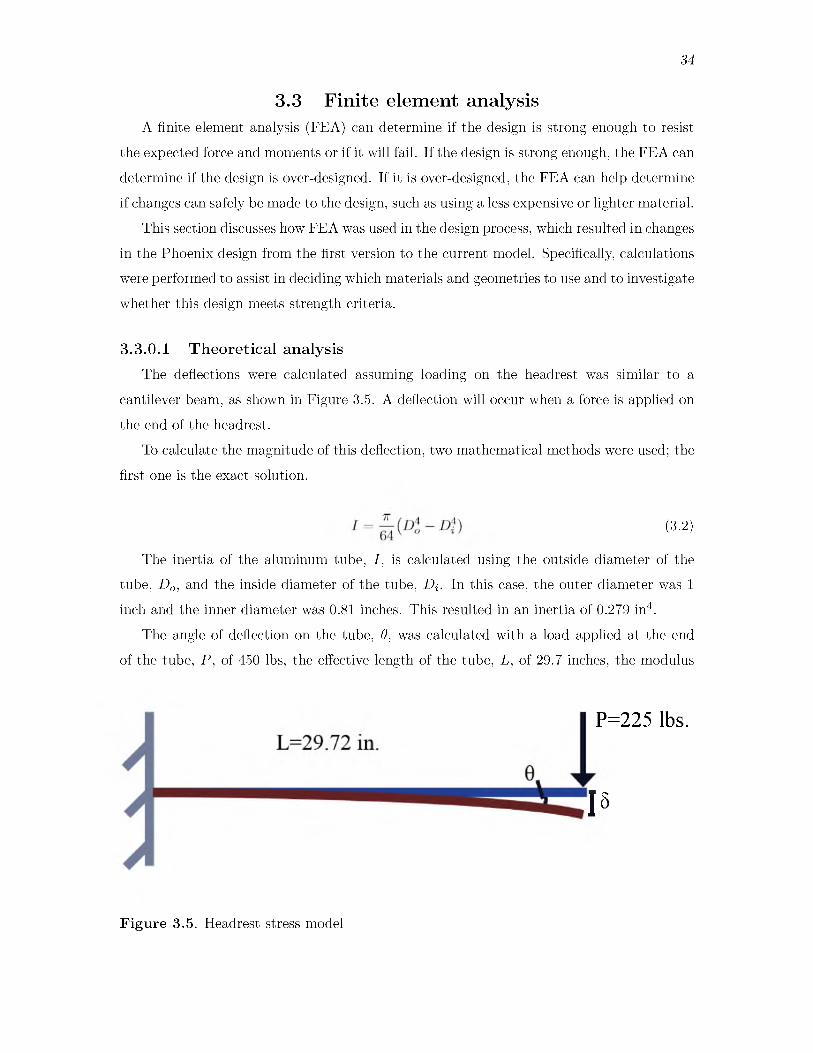
3 .3 .0 .1 T h e o re tic a l an a ly s isThe deflections were calculated assuming loading on the headrest was similar to a
cantilever beam, as shown in Figure 3.5. A deflection will occur when a force is applied on the end of the headrest.
To calculate the magnitude of this deflection, two mathematical methods were used; the first one is the exact solution.
The inertia of the aluminum tube, I , is calculated using the outside diameter of the tube, Do, and the inside diameter of the tube, Dj. In this case, the outer diameter was 1 inch and the inner diameter was 0.81 inches. This resulted in an inertia of 0.279 in4.
The angle of deflection on the tube, d, was calculated with a load applied at the end of the tube, P , of 450 lbs, the effective length of the tube, L, of 29.7 inches, the modulus
(3.2)
P=225 lbs.
1 5
F ig u re 3.5. Headrest stress model

35
of elasticity of aluminum, E a i , of 10.44 Mpsi, and the inertia, I . Though the maximum expected load is 300 lbs, a safety factor of 1.5 was used in all calculations.
* <3-3> The angle of deflection was found to be 0.342 radians. The elastic deflection of the tube,
5, was similarly calculated using the load applied at the end of the tube, P , the effective length of the tube, the modulus of elasticity of aluminum, E , and the inertia, I .
5 = SET <3-4>The elastic deflection was found to be 6.78 inches.
To calculate the angle of deflection and the elastic deflection using the second mathematical method, the matrices were used, as shown in Equation 3.5. This equation calculates the force matrix, F by multiplying the stiffness matrix, K , by the displacement matrix, D. Figure 3.6 shows the load applied on one end of the head rest with a fixed end. Equation 3.5 and 3.6 illustrate the matrix needed to calculate the deflection at the end of the tube.
[K] x [D] = [F] (3.5)After applying the boundary condition to this equation, the first and second columns
and first and second rows will be canceled. This cancellation is due to two reasons. First the tube being fixed at one end leads to the force Pi and the moment M 1 at that point equal to zero. Second, the elastic deflection at point 1, 51, and the angle of deflection at point 1, d1, is equal to zero. The force at point 2, P2, is 225 lbs and since there is no moment at point 2, M2, the moment is zero. After solving Equation 3.6, the elastic deflection, 52, was
F igure 3.6. The deflection and torsional deflection at the supported end

36
found to be 6.78 inches and the angular deflection at the same point, G2, was found to be 0.347 radians. These results align with the results from the previous method.
3 3( L > -3 3( L) " Si = 0 PiE I 3( 2
CM(4 - 3( D
CM(2- Gi = 0 M i2( L ? - 3 - 3 ( D 3 - 3 ( 2 S2 P2
,3( D CM(2 - 3 ( L| 4( D 2 . G2 M2
3.4 Push rod member stress calculation Phoenix 2.0Equation 3.7 was used to calculate the maximum stress at the headrest after applying
the load to see which outer diameter and wall thickness will be suitable to handle the load in the scenario where the Phoenix tips to the side or to the front
The maximum stress on the push rod (headrest| is calculated using Equation 3.7 by multiplying the moment on the headrest, M , by the radius of the tube, C , and then dividing this magnitude by the inertia of aluminum tube, I . By comparing the magnitude of the stress and the yield stress of aluminum, it was found that the minimum outer diameter should be 1.5 inches and not less than 0.125 inch wall thickness, as shown in Table 3.5.
M C (3 7|a = — (3J°
3.5 Calculation of the quick releaseAs previously mentioned, Phoenix 1.5 was designed to have a quick release in each
wheel to help with ease of assembly and disassembly. The diameter of this quick release is 0.47 inches (12 mm| outer diameter to fit the bearing of the wheels. This diameter is subjected to all the stresses from the landing impact and acts as a cantilever. There is also
Table 3.5. Stress calculationsOuterdiameter,D o
Innerdiameter,D i
Distance,L
Load,P
Moment,M
Radius,C
Moment of Inertia, I
Stress,a
Metric 0.0254 0.0205 0.7548 1001.18 755.77 0.0127 1048x10-11 826.26units m m m N Nm m m4 MPaAmerican 1 0.81 29.72 225 6687 0.5 0.0279 119.84units in. in. in. lbs lb.in. in. in4 ksiAccepted 1.5 1.25 29.72 225 6687 0.75 0.1284 39
in. in. in. lbs lb.in. inch in4 ksi
37
a bending moment on this quick release. In order to ensure failure of these shafts will not occur, analysis was performed to calculate the stresses and determine a suitable diameter for these parts. The maximum moment, M max, was found from the load applied on the quick release, P , multiplied by the length of the quick release, L . The worst-case scenario is if the Phoenix landed at an angle to the ground, resulting in the load being applied to one wheel. The resulting maximum moment on the quick release was calculated to be M max 1530 lb.in.
M max = P X L (3.8)The cross section modulus, Iy, found from the Equation 3.9 and also from Equation 3.10
using a diameter of the quick release, d, of 0.47 inches, shows the quick release will fail after applying 450 lbs force on one end. An allowable stress of high strength steel of 50 ksi was used. The analysis shows that a minimum diameter to handle the 450 lbs force using a steel quick release is 17.22 mm or 0.678 inches.
Iy = Mmax (3.9)Oallowable
nd3 ~32~
Equation 3.4 was then used to calculate the elastic deflection on the 0.47 inch quick release for a steel pin. With a modulus of elasticity of the steel, E steel, of 28000 ksi, a load applied on the quick release, P , equal to 450 lbs, the total length of the quick release, L , of3.4 inches, and an inertia, I , of 0.004 in.4, then the elastic deflection is 0.15 inch.
With the proposed Phoenix 2.0 design, the axle was recommended to be changed to a hollow aluminum hub with a 0.78 inch inner diameter and 0.12 inch wall thickness with an effective length of 3 inches. This part will take all the stresses caused by landing. These stresses will then be transmitted to an outer diameter thin steel rod of 0.2 inches that will complete the lock/unlock function. The analysis conducted for the proposed hub showed that the maximum stress on this hub will be 38.23 ksi below the yield stress of aluminum.
CHAPTER 4RESULTS AND DISCUSSION
4.1 Roll envelope for Phoenix 2.0A roll envelope for a vehicle protects the passenger from injury caused by impact,
pinching, or crushing. To calculate the roll envelope for the frame, two coordinates must be considered, shown in Figure 4.1. The first coordinate connects the top of the head rest to the top rear wheel. The passenger’s position related to this virtual line was evaluated using simple geometry. A head height of used was 38.3 inches. As mentioned previously, the head height for a 95 percentile male is 38.3 inches [8]. The initial headrest design allows the passenger’s head to extend past this envelope after he/she leans toward the wheel by about 20 degrees with the vertical axis. This scenario is likely to occur if the Phoenix rolls to the side.
The second coordinate connects the same top point of the head rest to the highest point of the front wheel. This is done to measure the roll envelope in case this wheel stops and the wings push the Phoenix forward. This is an unlikely scenario and has yet to been seen during taking off and landing; however, this scenario has still been considered. For this front rolling scenario, the previous dimensions place the passenger’s head barely outside the border of the envelope. Thus, both scenarios could lead to severe passenger injury with the previous headrest design.
The headrest has been redesigned to expand the roll envelop and thus protect a 95 percentile male passenger from these roll related injuries. The orange dotted line shown in Figure 4.1 represents the roll envelop proposed for the Phoenix 2.0 headrest design. This revised roll envelop protects the passenger in a side roll scenario. The new headrest designed to provide the revised roll envelop is shown in Figure 4.2.

39
Rear j Front
Wheel Wheel
Location Location
Figure 4.1. Roll envelop diagram
F ig u re 4.2. Phoenix 2.0 headrest

40
4.2 FEA results4 .2 .1 F ram e
Analysis was done to calculate maximum stress and deformation in these six landing condition. For this analysis, a load was applied to the frame according to the expected loading during these landing conditions. A load of 450 lbs was used to approximate the load expected due to the landing of the passenger and Phoenix together.
4 .2 .1 .1 C a lc u la tio n o f th e d y n a m ic im p u lse on th e fra m eThe dynamic impulse force on the frame was calculated using the following momentum
formula:
after impact, V2, in this case assumed to be zero, and the force applied during impact, F .Landing velocities, the velocity before impact, of 1 mph to 10 mph were used to estimate
the expected impulse force. Landings can vary greatly due to wind conditions on approach. The normal landing conditions appear to vary between a soft touch down where the device rolls in with little vertical velocity, 1 to 3 mph, to a faster landing believed to be closer to 8 mph from video analysis.
The impulse time is harder to estimate without high speed photography and instrumented equipment. The shocks and wheels allow for an elongation of the impulse time. Limited information was available on the shocks used, thus landing video was used to estimate reasonable impulse times. Impulse times between 0.1 and 0.5 seconds appear to be typical in a landing.
Table 4.1 and Figure 4.3 show the calculated forces across the landing speed and impulse times. The 450 lbs used for the following FEA are valid for only some of the landing conditions considered. Faster vertical descents and quicker impulses will result in much higher forces. If the combination of landing velocity and impulse result in a impulse force above 450 lbs, the FEA will not be valid for these conditions and further analysis should be considered.
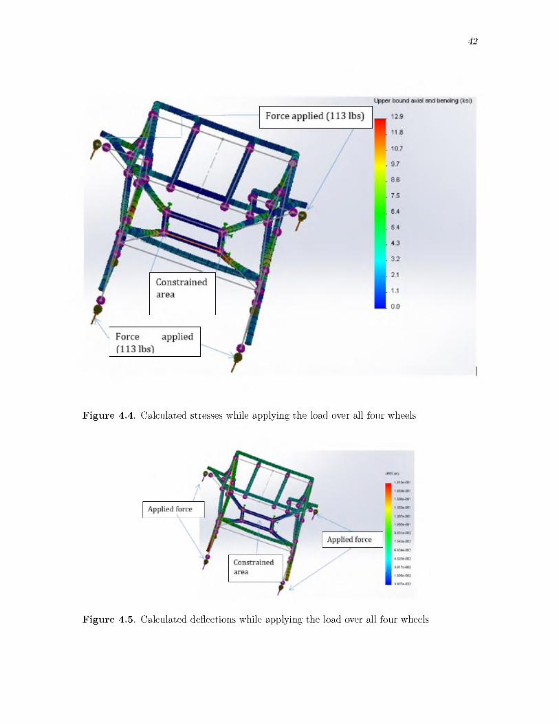
4 .2 .1 .2 F o u r w h ee l la n d in gThe first scenario considers a distributed four wheel loading as would be the case if
Phoenix has a normal flat landing. For the distributed loading over four wheels, a load of112.5 pounds was applied to each wheel. Figure 4.4 and Figure 4.5 show the calculated
(4.1)with the mass of the device, M , the vertical velocity prior to impact, Vi, the vertical velocity
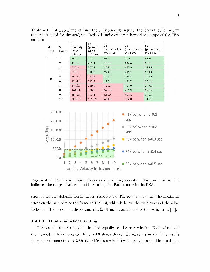
41
Table 4.1. Calculated impact force table. Green cells indicate the forces that fall within the 450 lbs used for the analysis. Red cells indicate forces beyond the scope of the FEA analysis
M[lbs.]
V[mph]
FI(pound] when t=0.1 sec
F2[pound] when t=0.2 sec
F3(pound]when t=0.3 sec
F4(pound]when t=0.4 sec
F5(pound]when t=0.5 sec
1 205.1 102.6 68.4 51.3 41.02 410.3 205.1 136.8 102.6 82.13 615.4 307.7 205.1 153.9 123.14 820.5 410.3 273.5 205.1 164.1
450 5 1025.7 512.8 341.9 256.4 205.16 1230.8 615.4 410.3 307.7 246.27 1435.9 718.0 478.6 359.0 287.28 1641.1 820.5 547.0 410.3 328.29 1846.2 923.1 615.4 461.6 369.210 2051.3 1025.7 683.8 512.8 410.3
2500.0
2000.0
£ 1500.0<u5 1000.0
500.0
0.0
•
<
f
»
*I*
»
*
1
• -A .> 1: *i« r * » ^
£ Q w ith in 450 lbs analysis]
1 2 3 4 5 6 7 8 9 10
Landing Velocity (miles per hour)
• F I (lbs) when t=0.1sec
• F2 (lbs) when t=0.2 sec
• F3 (Ibs)when t=0.3 sec
• F4 (Ibs)when t=0.4 sec
• F5 (Ibs)when t=0.5 sec
Figure 4.3. Calculated impact forces versus landing velocity. The green shaded box indicates the range of values considered using the 450 lbs force in the FEA.
stress in ksi and deformation in inches, respectively. The results show that the maximum stress on the members of the frame as 12.9 ksi, which is below the yield stress of the alloy, 40 ksi, and the maximum displacement is 0.181 inches on the end of the swing arms [11].
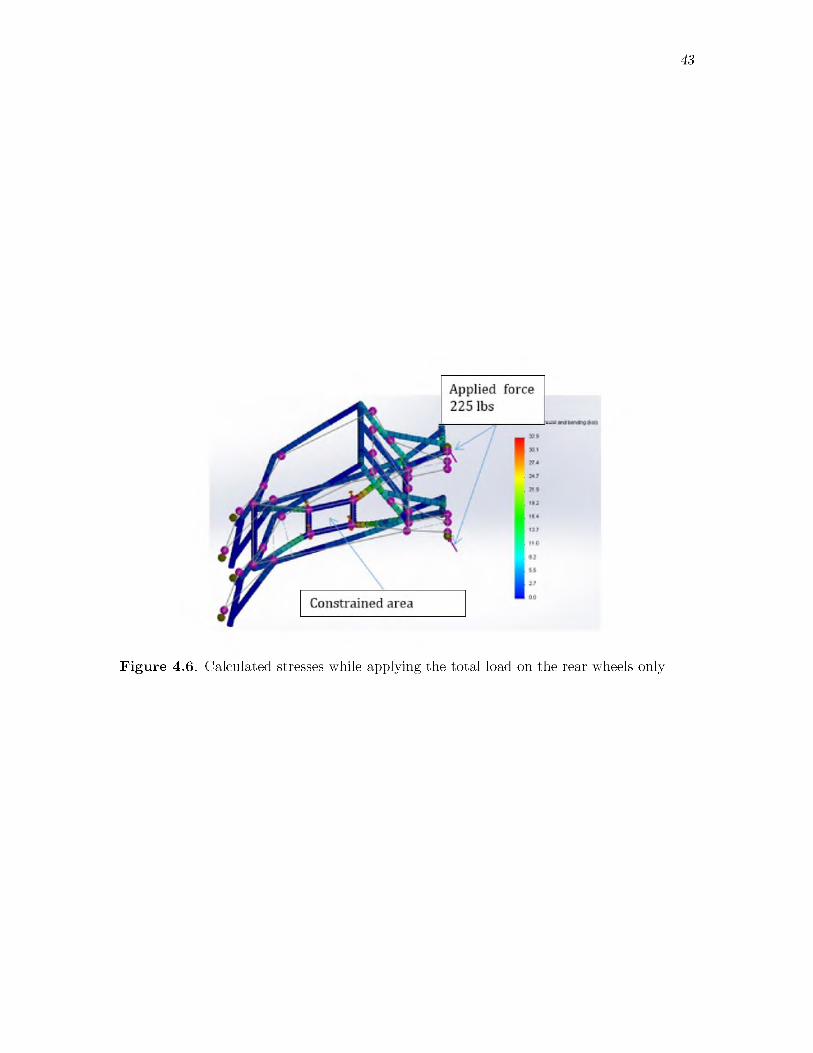
4 .2 .1 .3 D u a l r e a r w h ee l lan d in gThe second scenario applied the load equally on the rear wheels. Each wheel was
thus loaded with 225 pounds. Figure 4.6 shows the calculated stress in ksi. The results show a maximum stress of 32.9 ksi, which is again below the yield stress. The maximum
42
Figure 4.4. Calculated stresses while applying the load over all four wheels
F igure 4.5. Calculated deflections while applying the load over all four wheels
43
Figure 4.6. Calculated stresses while applying the total load on the rear wheels only
44
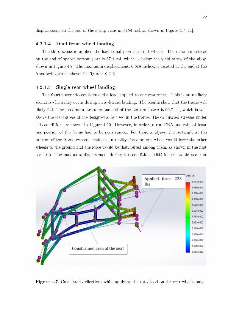
displacement on the end of the swing arms is 0.154 inches, shown in Figure 4.7 [11].
4 .2 .1 .4 D u a l f ro n t w h ee l lan d in gThe third scenario applied the load equally on the front wheels. The maximum stress
on the end of spacer bottom part is 37.4 ksi, which is below the yield stress of the alloy, shown in Figure 4.8. The maximum displacement, 0.618 inches, is located at the end of the front swing arms, shown in Figure 4.9 [11].
4 .2 .1 .5 S ing le r e a r w h ee l la n d in gThe fourth scenario considered the load applied to one rear wheel. This is an unlikely
scenario which may occur during an awkward landing. The results show that the frame will likely fail. The maximum stress on one end of the bottom spacer is 60.7 ksi, which is well above the yield stress of the designed alloy used in the frame. The calculated stresses under this condition are shown in Figure 4.10. However, in order to run FEA analysis, at least one portion of the frame had to be constrained. For these analyses, the rectangle at the bottom of the frame was constrained. In reality, force on one wheel would force the other wheels to the ground and the force would be distributed among them, as shown in the first scenario. The maximum displacement during this condition, 0.944 inches, would occur at
F ig u re 4.7. Calculated deflections while applying the total load on the rear wheels only

45
Figure 4.8. Calculated stresses while applying the total load on the front wheels only
F ig u re 4.9. Calculated deflection while applying the total load on the front wheels only

46
Figure 4.10. Calculated stresses while applying the total load vertically on one rear wheel
the end of the swing arm [11], shown in Figure 4.11.
4 .2 .1 .6 S ing le f ro n t w h ee l la n d in gThe fifth scenario considered the load applied to one front wheel. This is also an unlikely
scenario which may occur during an awkward landing. The results show that the frame will likely fail under this condition as well. In this scenario, the frame will fail at the end of the bottom spacer part. The maximum stress is calculated to be 63.4 ksi, which is above the yield stress of the aluminum frame tube. The calculated stresses for this scenario are shown in Figure 4.12. The calculated maximum displacement is 1.037 inches, as shown in Figure 4.13 [11].
Although the analysis shows that the frame would fail in this scenario, in reality, this is not expected to occur. There is a very low likelihood that the Phoenix would fall on only one wheel vertically. If the wheel hit an object vertically, the other wheels would hit the ground soon after. A single wheel landing would quickly transition to a 4 wheel landing. Despite the fact that the scenarios 4 and 5 rarely occur, it is important to test all possible landing options. This allows the designers to prepare for unique situations that could possibly happen and to potentially find a way to reinforce the design to compensate
47
Figure 4.11. Calculated deflections while applying the total load vertically on one rear wheel
F igure 4.12. Calculated stresses while applying the total load vertically on only one front wheel

48
Figure 4.13. Calculated deflections while applying the total load vertically on only one front wheel
for these unlikely cases [11].
4 .2 .1 .7 A n g led sin g le r e a r w h ee l lan d in gThe sixth scenario considered the load applied at 45 degrees to a single rear wheel.
The maximum calculated stress on the swing arm is 39.3 ksi, shown in Figure 4.14. As shown in Figure 4.14, the maximum stress is expected at the end of the swing arm near the quick release point. This stress is due to a moment being applied at this end with the force applied on the end of the rear wheel. This force was transferred from the wheel to the swing arm (quick release axle point) by multiplying the vertical component of the actual force by the radius of the wheel, 12 in. The calculated stress is still below the yield stress of the swing arm. The yield stress of annealed Chromalloy 4130 is 52.20 ksi [13]. The maximum calculated deflection is 0.716 inches, as shown in Figure 4.15 [11].
Throughout this analysis, the shock absorbers were removed from the model. The shock absorbers will act to cushion some of the landing forces unless they become jammed or fully compressed. In those worst-case scenarios, the entire system will act as a stiff member [14]. This analysis is considered representative of those worst-case shock failure scenarios.

49
Figure 4.14. Calculated stresses while applying the total load in 45 degree direction on only one of the rear wheels
F igure 4.15. Calculated deflections while applying the total load in 45 degree direction on only one of the rear wheels
50
4 .2 .2 H e a d re s tA finite element convergence analysis was conducted for the headrest. For this analysis,
the stresses were calculated using finite element methods at twenty locations within the high stress areas. The stresses at these locations were then averaged to find an average stress. The number of nodes in the finite element mesh was then increased and the average stress for the selected locations was calculated again. This process was repeated until the average stress reached a steady stress regardless of mesh density.
The convergence analysis was conducted for more than twenty tubing configurations. Five of the studied configurations including the final passing configurations will be discussed: 1) 1 inch outer diameter and 0.083 inch wall thickness, 2) 1 inch outer diameter and 0.095 inch wall thickness, 3) 1 inch outer diameter and 0.125 inch wall thickness, 4) 1.5 inch outer diameter and 0.083 inch wall thickness, and 5) 1.5 inch outer diameter and 0.125 inch wall thickness.
4 .2 .2 .1 A n a ly s is o f 1 inch o u te r d ia m e te r w ith 0 .083 inch w all th ic k n e ss
The results from ten iterations of stress analysis for 1 inch outer diameter and 0.083 inch wall thickness tubing are shown in Table 4.2. Figure 4.16 shows the relationship between number of elements and the stress (ksi). The visual display of stresses is shown in Figure 4.17. The analysis indicates this part will fail after applying 450 lbs to the headrest when the stresses exceed the yield stress of aluminum alloy, 40 ksi [15].
4 .2 .2 .2 A n a ly s is o f 1 inch o u te r d ia m e te r w ith 0 .095 inch w all th ic k n e ss
The results from ten iterations of stress analysis for 1 inch outer diameter and 0.095 inch wall thickness tubing are shown in Table 4.3. Figure 4.18 shows the relationship between number of elements and the stress (ksi). The visual display of stresses is shown in Figure 4.19. The analysis indicates this part will also fail after applying 450 lbs to the headrest.
4 .2 .2 .3 A n a ly s is o f 1 inch o u te r d ia m e te r w ith 0 .125 inch w all th ic k n e ss
The results from ten iterations of stress analysis for 1 inch outer diameter and 0.125 inch wall thickness tubing are shown in Table 4.4. Figure 4.20 shows the relationship between number of elements and the stress (ksi). The visual display of stresses is shown break in
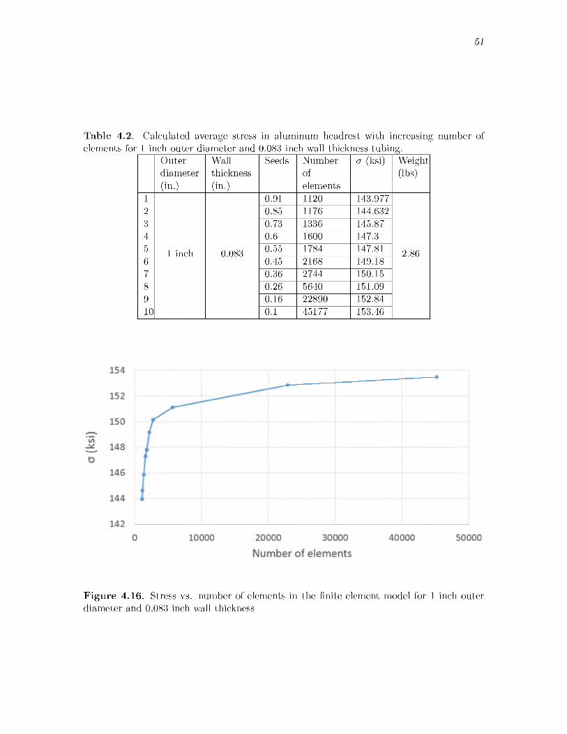
51
T able 4.2. Calculated average stress in aluminum headrest with increasing number ofelements for 1 inch outer diameter and 0.083 inch wall thickness tubing.
Outerdiameter(in.)
Wallthickness(in.)
Seeds Numberofelements
a (ksi) Weight(lbs)
1 0.91 1120 143.9772 0.85 1176 144.6323 0.73 1336 145.874 0.6 1600 147.35 1 inch 0.083 0.55 1784 147.81 2.866 0.45 2168 149.187 0.36 2744 150.158 0.26 5640 151.099 0.16 22890 152.8410 0.1 45177 153.46
F ig u re 4.16. Stress vs. number of elements in the finite element model for 1 inch outerdiameter and 0.083 inch wall thickness
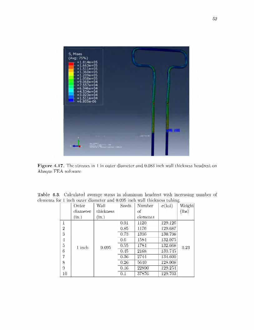
52
Figure 4.17. The stresses in 1 in outer diameter and 0.083 inch wall thickness headrest on Abaqus FEA software
Table 4.3. Calculated average stress in aluminum headrest with increasing number of elements for 1 inch outer diameter and 0.095 inch wall thickness tubing.
Outerdiameter(in.)
Wallthickness(in.)
Seeds Numberofelements
k i Weight(lbs)
1 0.91 1120 129.1262 0.85 1176 129.6873 0.73 1336 130.7984 0.6 1584 132.0755 1 inch 0.095 0.55 1784 132.668 3.236 0.45 2168 133.7457 0.36 2744 134.6008 0.26 5640 128.0089 0.16 22890 129.25410 0.1 37876 129.703

a (k
si)
53
Number of elements
Figure 4.18. Stress vs. number of elements in the finite element model for 1 inch outer diameter and 0.095 inch wall thickness
F igure 4.19. The stresses in 1 in outer diameter and 0.095 inch wall thickness headrest on Abaqus FEA software
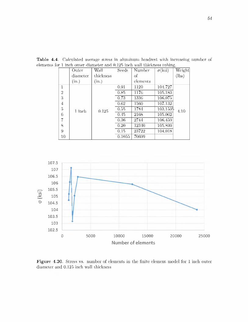
a (k
si)
54
T able 4.4. Calculated average stress in aluminum headrest with increasing number ofelements for 1 inch outer diameter and 0.125 inch wall thickness tubing.
Outerdiameter(in.)
Wallthickness(in.)
Seeds Numberofelements
k i Weight(lbs)
1 0.91 1120 104.7272 0.85 1176 105.1833 0.73 1336 106.0754 0.62 1560 107.1325 1 inch 0.125 0.55 1784 103.1535' 4.106 0.45 2168 105.0627 0.36 2744 106.4598 0.20 12340 105.8999 0.15 23722 104.01810 0.1055 70699
107.5 107
106.5 106
105.5 105
104.5 104
103.5 103
102.50 5000 10000 15000 20000 25000
Number of elements
F ig u re 4.20. Stress vs. number of elements in the finite element model for 1 inch outerdiameter and 0.125 inch wall thickness

55
Figure 4.21. The analysis indicates this part will also fail after applying 450 lbs to the headrest.
4 .2 .2 .4 A n a ly s is o f 1.125 inch o u te r d ia m e te r w ith 0 .083 inch w all th ic k n e ss
The results from ten iterations of stress analysis for 1.125 inch outer diameter, 0.083inch wall thickness are shown in Table 4.5. Figure 4.22 shows the relationship betweennumber of elements and the stress (ksi). The analysis indicates this part will also fail afterapplying 450 lbs to the headrest. The visual display of stresses is shown in Figure 4.23.
4 .2 .2 .5 A n a ly s is o f 1.5 inch o u te r d ia m e te r w ith 0 .125 inch w all th ic k n e ss
The results from ten iterations of stress analysis for 1.5 inch outer diameter and 0.125inch wall thickness tubing are shown in Table 4.6. Figure 4.24 shows the relationshipbetween number of elements and the stress (ksi). The visual display of stresses is shown inFigure 4.25 [16]. The maximum stress for the 1.5 inch outer diameter with 0.125 inch wallthickness, 35.7 ksi, is expected to be below the yield stress of aluminum. Thus, this part isnot expected to yield after applying the 450 pound load.
F igure 4.21. The stresses in 1 in outer diameter and 0.125 inch wall thickness headrest on Abaqus FEA software
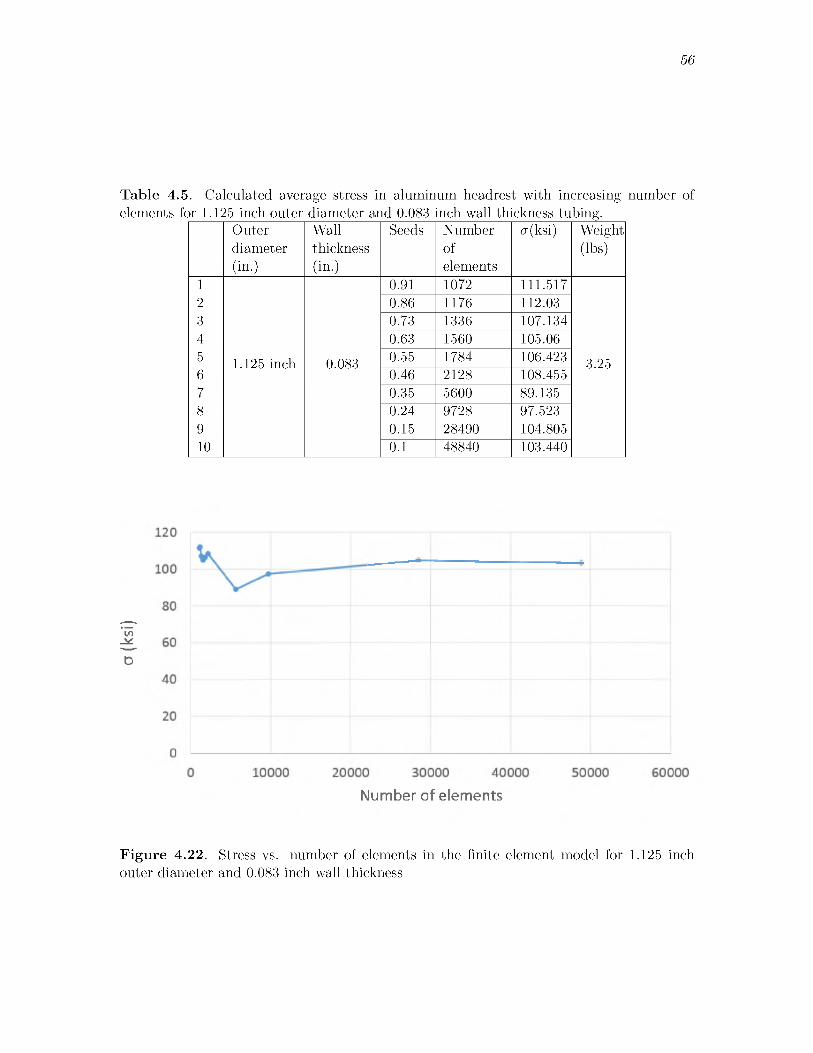
o (ksi)
56
T able 4.5. Calculated average stress in aluminum headrest with increasing number ofelements for 1.125 inch outer diameter and 0.083 inch wall thickness tubing.
Outerdiameter(in.)
Wallthickness(in.)
Seeds Numberofelements
a(ksi) Weight(lbs)
1 0.91 1072 111.5172 0.86 1176 112.033 0.73 1336 107.1344 0.63 1560 105.065 1.125 inch 0.083 0.55 1784 106.423 3.256 0.46 2128 108.4557 0.35 5600 89.1358 0.24 9728 97.5239 0.15 28490 104.80510 0.1 48840 103.440
Number of elements
F ig u re 4.22. Stress vs. number of elements in the finite element model for 1.125 inchouter diameter and 0.083 inch wall thickness

57
Figure 4.23. The stresses in 1.125 in outer diameter and 0.083 inch wall thickness headrest on Abaqus FEA software
Table 4.6. Calculated average stress in aluminum headrest with increasing number ofr 1.5 inch outer diameter and 0.125 inch wall thic kness tubing.
Outer Wall Seeds Number si(ka( Weightdiameter thickness of (lbs|(in0 (in0 elements
1 0.91 1072 40.8592 0.80 1240 38.2553 0.70 1376 39.7324 0.55 1784 40.97455 1.5 inch 0.125 0.46 4256 32.115 6.456 0.34 9360 36.6427 0.20 19616 39.2568 0.105 61480

58
0 5000 10000 15000 20000 25000
Number of elements
Figure 4.24. Stress vs. number of elements in the finite element model for 1.5 inch outer diameter and 0.125 inch wall thickness
F igure 4.25. The stresses in 1.5 in outer diameter and 0.125 inch wall thickness headrest on Abaqus FEA software
59
A finite element analysis was conducted in Solidworks [17] to confirm the results with an alternative method. The maximum calculated stress for the 1 inch outer diameter and 0.095 inch wall thickness aluminum tubing headrest was found to be 107.9 ksi, shown in Figure 4.26. This Solidworks calculated stress above the yield stress of aluminum, 40 ksi, would indicate the headrest is expected to fail using the Solidworks software as well.
For the 1.5 inch outer diameter and 0.125 inch wall thickness tubing part, the stresses are expected to below the yield stress of aluminum. The maximum calculated stress was 35.7, as shown in Figure 4.27. The difference in value between Abaqus and Solidworks calculations is due to Abaqus’s increased tool set and options to make it more accurate.

60
Figure 4.26. The stresses in 1 inch outer diameter and 0.095 inch wall thickness headrest using Solidworks

61
Figure 4.27. The stresses in 1.5 in outer diameter and 0.125 in wall thickness of headrest using Solidworks software
CHAPTER 5RECOMMENDATIONS
5.1 FrameThe finite element analysis of the aluminum frame shows that the proposed tube sizing
of the frame and swing arms passes the stress analysis for even the worst-case scenarios. Despite passing the FEA stress analysis testing, there is some possibility of failure of the wheel itself. If the wheel is not designed to handle the entire landing force, then some of the spokes may break. This failure could potentially cause serious injury to the passenger. In order to avoid this, it is recommended to use heavyduty mountain bike wheels and a rigorous maintenance program should be enacted to replace them regularly. Also, the quick release used in the Phoenix 1.5 needs to be revised, changing to aluminum hub with a thin steel rod used for the lock mechanism.
Additionally, further consideration is warranted for the wing connection bar, shown in Figure 5.1. This bar helps balance the chair in the air according to the weight of the pilot/passenger and the wing size. This component is critical while in the air. If the weight is above or below the designed range of the wings, the flight characteristics may change and affect the safety of that flight.
5.2 HeadrestAlternative designs for the head rest are shown in Figure 5.2. Potential improvements
include changing the way the headrest is fabricated. Decreasing the number of bends and replacing them with welds will allow the same performance but will likely decrease fabrication costs.
To widen the envelope within which the pilot will be safe, there are many options: increasing the height or width of the head rest, or widening the dimension between the rear wheels would all increase this safe envelope. However, the base is already quite wide, making that a less ideal option. The recommended solution is to increase the head rest width to 17 inches from the center of the head rest to the outer edge by adding triangular

63
Figure 5.1. Frame and swing suspension arms assembly
structures of the same pipe material. This headrest design is shown in Figure 5.2. This change will expand the safe envelope to the sides of the Phoenix. This is especially important in the event of a side tip event. In this case, the tips of the added triangular headrest and rear wheels will be able to protect the pilot’s head. As an added bonus, these triangular structures can also be used as handles by the trainer. The suggested roll envelop is shown in Figure 5.3.
For the second scenario (Phoenix will collapse to the front), we either raise the height of the head rest or make an extension with angle of 45 degrees with a horizontal dimension of 7.5 inches from the center of the head rest pipe to the end of the angle.
Table 5.1 shows the different sizes of outer diameter and wall thickness aluminum tube with their weight for each size and the actual stress after applying 450 lbs.
The results of an FEA analysis for the new version of the headrest are shown in Figure 5.4 and Table 5.1. This result shows that the previous version will likely fail, potentially causing serious injury to the passenger during a tipping event. The analysis shows that minimum outer diameter should be 1.5 inch and the wall thickness no less than 0.125 inch for aluminum 6061-T6 alloy tubing. This will increase the weight of this part to 6.45 pounds instead of the original weight of 2.45 lbs with the 1 inch diameter and 0.083 wall thickness tubing.
The device as currently designed in Phoenix 1.0 and 1.5 may not be able to handle the worst-case scenarios. In order to fully handle these conditions, either thicker walled tubing or changing the aluminum material to Chromalloy is recommended. Both of these solutions will increase the weight and raise the total cost, both of which are not ideal.

64
F ig u re 5.3. Roll envelope dimensions to be recommended

Wei
ght
{lbs)
65
Table 5.1. Outer diameter and wall thickness with maximum stress and their weights in pound. _________________________________________________________
OuterDiameter(in)
WallThickness(in)
a (ksi) Aluminum6061T6Weight(lbs)
Chromalloy4031Weight(lbs)
1 1 0.083 131.09 2.86 8.32 1 0.095 126.254 3.23 9.383 1 0.125 104.018 4.1 11.934 1.125 0.083 103.44 3.25 9.445 1.25 0.125 61.362 5.28 15.346 1.375 0.125 48.335 5.86 17.057 1.5 0.125 39.256 6.45 18.75
F igure 5.4. The maximum stress (ksi) and the weight of head rest in pounds

CHAPTER 6CONCLUSION
The Phoenix paragliding system is designed for persons with disabilities and allows these persons to be trained and qualified to use this device as solo pilots [7]. This device provides adequate torso support and shock absorbers on each wheel help to reduce the impact loading during landing phase [7]. The first applicable test for Phoenix was in Sun Valley, Idaho in the summer of 2011. During this time, five injured military veterans were trained to fly in a solo-tandem pair using the Phoenix 1.0 and 1.5 [7]. The next training was in April 2012 in Santa Barbara, California. This training session had three purposes: 1) to test the new device, 2) to fully certify the veterans as paraglider pilots, and 3) to get feedback from operators. This feedback was used to enhance and develop the device to better match their needs [7].
The proposed version, Phoenix 2.0, has benefited from analytical design processes and computational modeling before fabrication. This allowed the current design to improve safety, cost, and reliability.
Phoenix 2.0 is designed in a simple shape with fewer curves and more welded points to reduce the fabrication cost. The frame shall be constructed of aluminum 6061 T6 tube with outer diameter of 1 in. and with 0.125 in. wall thickness. The swing arms shall be constructed of annealed Chromalloy 4031 with 1 in. outer diameter and 0.065 in. wall thickness. The swing arms are attached to the frame and include shock absorbers on each wheel. The design of the frame has been changed to be narrower and has been angled toward the back to support the pilot and prevent the pilot's body from slipping to the front.
The headrest has been redesigned to increase the roll envelope and protect the pilot in case of accidents. The headrest is made of aluminum 6061-T6 with outer diameter of1.5 inches and 0.125 inch wall thickness. It is adjustable and will protect 95% of the male population [8].
67
The footrest has been redesigned to have more degrees of freedom in order to increase comfort and to protect the feet of a disabled pilot.
The Phoenix 2.0 rear wheels are proposed to be 24 inch heavy duty mountain bike wheels. The front wheels are the same, but slightly smaller at 20 inches. Each wheel has been redesigned to use a quick release using an aluminum hub with a thin steel rod. The hub has inside diameter of 20 mm with 3 mm wall thickness. The effective length of the new hub is 75 mm.
The Phoenix 2.0 is the latest, but likely not the last, version of the Phoenix family of paragliding systems. This proposed version incorporates the results of considerable analysis, but development will continue on the Phoenix in order to further exceed customer expectations.
REFERENCES[1] N. Whittall, Paragliding: The Complete Guide. Globe Pequot, 2000.[2] D. Pagen, The A rt o f Paragliding. Black Mountain Books, 2001.[3] Circling Hawk Paragliding. History of paragliding. [Online]. Available:
http://www.circlinghawk.com/history.html[4] M. Steed, “2010 US paragliding injury summary,” The United States Hang Gliding and
Paragliding Association, 2012.[5] French Federation of Free Flight, “2011 member accident report,” French Federation
of Free Flight (FFVL), 2012.[6] A. Sulzberger, “Accustomed to wheels, thrill-seeking injured veterans take wing,” New
York Times, 2011.[7] C. Stites. (1999) Able Flight 2013. [Online]. Available: http://ableflight.org[8] S. Pheasant, “Bodyspace: Anthropometry,” Ergonomics and Design, vol. 2, 1986.[9] B. Goldberg, “Lecture notes in Fundamentals in System Engineering,” University of
Utah, February 2013.[10] C. A. Ericson, Hazard Analysis Techniques for System Safety. John Wiley & Sons,
2005.[11] A. Kossiakoff, W. N. Sweet, S. Seymour, and S. M. Biemer, Systems Engineering
Principles and Practice. John Wiley & Sons, 2011, vol. 83.[12] S. Moaveni, Finite Element Analysis: Theory and Application with A N S Y S . Pearson
Education India, 2003.[13] Eagle Steel, “Normalized alloy steel - Eagle National,” 2009. [Online]. Available:
http://www.eaglesteel.com/download/techdocs/4130.pdf[14] J. Gere and B. Goodno, Mechanics of Materials. Cengage Learning, 2009.[15] F. P. Beer and E. R. Johnston Jr, Mechanics of Materials. New York: McGraw-Hill,
Inc, 1974.[16] DassaultSystems. Abaqus FEA software - finite element analysis - Dassault. [Online].
Available: http://www.3ds.com/products-services/simulia/products/abaqus/latest- release/
[17] DassaultSystems, “Finite element analysis - Solidworks.” [Online]. Available: http://www.solidworks.com/sw/products/simulation/finite-element-analysis.htm